US8831175B2 - Hybrid X-ray optic apparatus and methods - Google Patents
Hybrid X-ray optic apparatus and methods Download PDFInfo
- Publication number
- US8831175B2 US8831175B2 US13/698,786 US201113698786A US8831175B2 US 8831175 B2 US8831175 B2 US 8831175B2 US 201113698786 A US201113698786 A US 201113698786A US 8831175 B2 US8831175 B2 US 8831175B2
- Authority
- US
- United States
- Prior art keywords
- optic
- gimso
- capillary
- rays
- hybrid
- Prior art date
- Legal status (The legal status is an assumption and is not a legal conclusion. Google has not performed a legal analysis and makes no representation as to the accuracy of the status listed.)
- Expired - Fee Related
Links
Images


Classifications
-
- G—PHYSICS
- G21—NUCLEAR PHYSICS; NUCLEAR ENGINEERING
- G21K—TECHNIQUES FOR HANDLING PARTICLES OR IONISING RADIATION NOT OTHERWISE PROVIDED FOR; IRRADIATION DEVICES; GAMMA RAY OR X-RAY MICROSCOPES
- G21K1/00—Arrangements for handling particles or ionising radiation, e.g. focusing or moderating
-
- G—PHYSICS
- G21—NUCLEAR PHYSICS; NUCLEAR ENGINEERING
- G21K—TECHNIQUES FOR HANDLING PARTICLES OR IONISING RADIATION NOT OTHERWISE PROVIDED FOR; IRRADIATION DEVICES; GAMMA RAY OR X-RAY MICROSCOPES
- G21K1/00—Arrangements for handling particles or ionising radiation, e.g. focusing or moderating
- G21K1/06—Arrangements for handling particles or ionising radiation, e.g. focusing or moderating using diffraction, refraction or reflection, e.g. monochromators
- G21K1/067—Arrangements for handling particles or ionising radiation, e.g. focusing or moderating using diffraction, refraction or reflection, e.g. monochromators using surface reflection, e.g. grazing incidence mirrors, gratings
-
- G—PHYSICS
- G21—NUCLEAR PHYSICS; NUCLEAR ENGINEERING
- G21K—TECHNIQUES FOR HANDLING PARTICLES OR IONISING RADIATION NOT OTHERWISE PROVIDED FOR; IRRADIATION DEVICES; GAMMA RAY OR X-RAY MICROSCOPES
- G21K2201/00—Arrangements for handling radiation or particles
- G21K2201/06—Arrangements for handling radiation or particles using diffractive, refractive or reflecting elements
- G21K2201/067—Construction details
Definitions
- GEMSO grazing incidence multi-shell optic
- Another GIMSO design includes a surface shaped into a cylindrical spiral for single reflection, point-to-point focusing.
- the spiral surface may be a ribbon of smooth plastic coated with any one or combination of metals such as nickel, gold or iridium, or other suitable materials (e.g., high Z materials), and may be coated with multiple layers of such materials.
- metals such as nickel, gold or iridium, or other suitable materials (e.g., high Z materials)
- a GIMSO may be formed from concentric cylinders of the same material.
- Other configurations of metal coated plastic may be used as well to guide, focus and/or concentrate x-rays.
- capillary optics typically formed from bundles of capillary tubes. In such capillary bundles, the x-rays undergo numerous reflections as they travel through the glass channels.
- the individual capillaries typically have lower efficiency than the GIMSO type optics discussed above and typically have significantly shorter focal lengths.
- the extremely large number of capillaries per solid angle of collection makes the ultimate throughput of the capillary system relatively high, and may have relatively large opening or acceptance angles as compared to GIMSO type optics.
- capillary optics may be formed from any type of suitable material, and the term capillary optic refers herein to any optic formed from a collection of capillary tubes of any suitable material.
- capillary optics guide x-rays using multiple reflections (e.g., 5, 10 or even hundreds or more reflections).
- Some embodiments include a hybrid optic comprising a capillary optic for receiving x-rays from an x-ray source at an entrance portion of the capillary optic and for providing x-rays at an exit portion of the capillary optic, and a grazing incidence multi-shell optic (GIMSO) coupled, at an entrance portion of the GIMSO, to the exit portion of the capillary optic to receive x-rays emerging from the exit portion of the capillary optic.
- GIMSO grazing incidence multi-shell optic
- Some embodiments include an apparatus comprising an electron source capable of generating electrons to irradiate at least one sample to produce x-rays, a capillary optic for receiving x-rays emitted from the at least one sample in response to being irradiated at an entrance portion of the capillary optic and for providing x-rays at an exit portion of the capillary optic, a grazing incidence multi-shell optic (GIMSO) coupled, at an entrance portion of the GIMSO, to the exit portion of the capillary optic to receive x-rays emerging from the exit portion of the capillary optic, the GIMSO including an exit portion for providing x-rays, and at least one detector arranged to receive x-rays provided from the exit portion of the GIMSO.
- an electron source capable of generating electrons to irradiate at least one sample to produce x-rays
- a capillary optic for receiving x-rays emitted from the at least one sample in response to being irradiated at
- Some embodiments include configurations combining one or more of the following: (1) a capillary optic configured to receive substantially diverging x-rays at the entrance portion and to provide substantially diverging x-rays at the exit portion of the capillary optic; (2) a GIMSO configured to receive the substantially diverging x-rays from the exit portion of the capillary optic and to provide substantially converging x-rays at the exit portion of the GIMSO; (3) a capillary optic configured to receive substantially diverging x-rays at the entrance portion and to provide substantially parallel x-rays at the exit portion of the capillary optic; and/or (4) a GIMSO configured to receive the substantially parallel x-rays from the exit portion of the capillary optic and to provide substantially converging x-rays at the exit portion of the GIMSO.
- Some embodiments include a hybrid optic wherein a GIMSO is a single reflection optic or a double reflection optic. Some embodiments include a hybrid optic wherein the GIMSO includes one or more of the following: (1) a cylindrical spiral geometry; (2) a conical spiral geometry; (3) a nested cylinder geometry; and/or (4) a first surface positioned to reflect x-rays provided by the capillary optic and a second surface to reflect x-rays reflected from the first parabolic surface, wherein the first surface is a parabolic surface or a flat surface approximation and the second surface is a parabolic surface (or flat surface approximation), or a hyperbolic surface (or a conical surface approximation).
- FIG. 1 is a schematic of a an exemplary scanning electron microscopy system which includes an x-ray optic and x-ray detector;
- FIG. 2 illustrates a GIMSO in connection with a scanning electron microscope that generates a divergent beam of x-rays
- FIG. 3 illustrates a GIMSO in connection with a scanning electron microscope that generates a divergent beam of x-rays
- FIG. 4 illustrates an exemplary GIMSO type nested foil optic concentrator
- FIG. 5 illustrates an exemplary GIMSO type spiral foil optic concentrator
- FIG. 6 illustrates a point-to-point capillary type optic
- FIG. 7 illustrates a point-to-parallel capillary type optic
- FIG. 8 schematically illustrates a point-to-point capillary type optic and a point-to-point GIMSO drawn to the same relative scale
- FIG. 9 illustrates solid angle of collection variation with energy for a GIMSO coated with nickel, an aperture diameter of 25 mm and input and output focal distances of 485 mm;
- FIG. 10 illustrates a hybrid optic formed from a capillary optic portion and a GIMSO portion
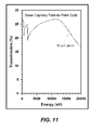
- FIG. 11 illustrates energy bandpass for transmission of point-to-point capillary optics with 10 ⁇ m diameter pores
- FIG. 12 illustrates improvement in the solid angle of collection that may be achieved using some embodiments of a hybrid optic
- FIG. 13A illustrates an embodiment of a hybrid optic formed by a point-to-diverging capillary optic coupled to a cylindrical spiral GIMSO;
- FIG. 13B illustrates a cross-section of the GIMSO along the cross-sectional cut 1365 shown on the right side of the GIMSO portion in FIG. 13A ;
- FIG. 14A illustrates an embodiment of a hybrid optic formed by a point-to-diverging capillary optic coupled to a nested cylindrical shell GIMSO;
- FIG. 14B illustrates a cross-section of the GIMSO along the cross-sectional cut 1465 shown on the right side of the GIMSO portion in FIG. 14A ;
- FIG. 15A illustrates an embodiment of a hybrid optic formed by a point-to-parallel capillary optic coupled to a conical spiral GIMSO;
- FIG. 15B illustrates a cross-section of the GIMSO along the cross-sectional cut 1565 shown on the right side of the GIMSO portion in FIG. 15A ;
- FIG. 16A illustrates an embodiment of a hybrid optic formed by a point-to-parallel capillary optic coupled to a Kirkpatrick-Baez GIMSO;
- FIG. 16B illustrates a cross-section of the GIMSO along the cross-sectional cut 1665 shown on the right side of the GIMSO portion in FIG. 16A ;
- FIG. 17A illustrates an embodiment of a hybrid optic formed by a point-to-parallel capillary optic coupled to a Wolter type GIMSO;
- FIG. 17B illustrates a cross-section of the GIMSO along the cross-sectional cut 1765 shown on the right side of the GIMSO portion in FIG. 17A .
- Scanning electron microscopes are widely used for materials and biomedical analysis. When targets are bombarded with electrons, x-rays are generated as a side effect. The x-ray spectrum provides information about elements contained in the target so that x-rays are often detected for analytical purposes.
- a detector such as a lithium-drifted silicon or germanium detector may be positioned very close to the target in a scanning electron microscope. Such detectors may be mounted on the end of a cold finger cooled by thermal conduction by means of a quantity of liquid nitrogen which boils at 77 Kelvin. Higher spectral resolution can be achieved utilizing detectors such as microcalorimeters cooled to approximately 0.06 Kelvin.
- FIG. 1 shows an exemplary SEM device, which includes a electron source 110 to generate electrons (e.g., an electron beam e ⁇ ) to bombard a sample 105 which, in response, generate x-rays 115 .
- the generated x-rays 115 are guided through x-ray optic 120 to cryostat 130 where they can be detected by microcalorimeter 140 .
- the x-ray optic includes a electron source 110 to generate electrons (e.g., an electron beam e ⁇ ) to bombard a sample 105 which, in response, generate x-rays 115 .
- the generated x-rays 115 are guided through x-ray optic 120 to cryostat 130 where they can be detected by microcalorimeter 140 .
- the x-ray optic There are a number of considerations for the x-ray optic.
- the distance of the source of X-rays to the front surface of the optic often has a maximum distance to permit collection of a desired amount of X-rays by the microcalorimeter in a desired time (e.g., 0.1 meters).
- a hybrid optic e.g., an optic formed partially of the capillary optic type and partially of the GIMSO type
- a hybrid optic may be utilized to exploit the advantages of both types.
- some embodiments of a hybrid optic may be used to satisfy the requirements of a given application, such as a SEM having particular distance requirements.
- a hybrid optic formed partially from a capillary optic and partially from a GIMSO may be of to any type suitable for collecting and focusing x-rays.
- the GIMSO may be of any suitable type.
- a capillary bundle and GIMSO used in a hybrid optic may be any one or combination of the types described in U.S. Pat. No. 6,594,337, entitled “X-ray Diagnostic System,” which is herein incorporated by reference in its entirety.
- FIGS. 2 and 3 illustrate such GIMSOs in connection with a scanning electron microscope 10 that generates a divergent beam of x-rays 12 .
- the x-rays 12 impinge upon a single reflection cylindrical or cylindrical spiral foil concentrator 18 and are focused on a spectrometer 16 .
- the diverging beam of x-rays 12 encounters a nested conical or conical spiral foil optic concentrator 22 which similarly focuses the x-rays 12 on the spectrometer 16 .
- FIGS. 4 and 5 Two examples of GIMSO type foil concentrators are shown in FIGS. 4 and 5 .
- a cylindrical or conical concentrator 24 includes nested concentric cylinders or cones 26 , 28 , 30 , etc.
- the concentric cylinders or cones are formed from a thin ribbon of a gold-coated plastic.
- the nested cylinders or cones 26 , 28 , 30 , . . . may also be made of glass, aluminum foil, silicon or germanium.
- a spiral concentrator 32 shown in FIG. 5 is formed of a relatively long single ribbon 34 that is wound into a spiral.
- the ribbon 34 may be gold-coated plastic, aluminum foil or quartz ribbon. Suitable plastic materials for the embodiments in FIGS.
- FIGS. 4 and 5 include polyester, polyimide, KaptonTM, melinex, hostaphan, apilcal, mylar or any suitably smooth, flexible material.
- One suitable plastic is available from the Eastman Kodak Company under the designation ESTARTM. Such plastic foil may range from 0.004 to 0.015 inches thick, for example.
- the plastic material may be coated with a thin layer of metal, preferably a high Z metal such as nickel, gold or iridium and may be coated with multilayers. A suitable thickness for the metal coating is approximately 800 ⁇ . Evaporation or sputtering is a suitable technology for applying the metal coating to the plastic ribbon material 34 .
- the embodiments of FIGS. 4 and 5 may be configured for single reflection as illustrated in FIG. 2 or for multiple reflections as illustrated in FIG. 3 .
- Some embodiments of the x-ray optics shown in FIGS. 4 and 5 use a point-to-point geometry to obtain relatively significant gain and solid angle in the energy band of 0.1 keV to 10 keV.
- the gain depends upon the x-ray reflectivity, focal distance, the width of the ribbon material and the number of windings of the spiral or the number of nested cylinders.
- the x-ray reflectivity of the concentrators 24 and 32 can be improved by depositing multilayers of W—C, Co—C, or Ni—C for example, on the uncoated or metal-coated plastic which allow the designs to include larger grazing angles, but only in a select band of energies.
- a GIMSO of the cylindrical spiral concentrator type (e.g., cylindrical spiral concentrator 32 ) are constructed using a single reflection in a point-to-point geometry in which the ribbon is wound with a pitch of ⁇ 0.05 inches and has ⁇ 19 windings within an entrance aperture with diameter of ⁇ 50 mm.
- the ribbon may be cut into approximately 20 lengths to form concentric cylinders.
- the ribbon width and focal length of some embodiments may be, but are not limited to, approximately 25 mm and 1.5 m, respectively.
- Such x-ray optics may be suitable, for example, for an SEM in which the distance between the x-ray source of the SEM and an energy dispersive detector (e.g., a lithium-drifted silicon detector and/or x-ray microcalorimeter) is approximately two meters.
- an energy dispersive detector e.g., a lithium-drifted silicon detector and/or x-ray microcalorimeter
- GIMSOs of any geometry, properties and characteristics may be chosen to satisfy requirements of a given application, as the aspects of the invention are not limited to any particular type of GIMSO nor to GIMSO having any particular set of parameter values.
- a GIMSO of a single reflection type (e.g., cylindrical and spiral configurations) or double reflection types may be made of machined metal construction to form, for example, the cylinder and/or spiral geometries from rigid surfaces rather than being constructed from a material that can be bent or shaped into those geometries, such as the materials described above.
- FIGS. 6 and 7 illustrate capillary bundle type x-ray optics.
- the diverging beam of x-rays 12 pass through point-to-point capillary bundle 20 which focuses the x-rays 12 onto the spectrometer 16 .
- multiple reflection point-to parallel, parallel-to-point capillary bundles 22 similarly focus the beam 12 onto the spectrometer 16 .
- FIG. 7 also represents a point-to-parallel followed by a parallel-to-point concentrator.
- Different configurations of capillary optics may be suitable to form part of a hybrid x-ray optic.
- portions of the capillary type x-ray optic and portions of the GIMSO type x-ray optic may be used together to form a hybrid x-ray optic.
- a first portion of the hybrid optic is formed from a capillary optic and a second portion of the hybrid optic is formed from a GIMSO.
- the capillary optic portion is arranged to receive x-rays from an x-ray source and provide the x-rays to the GIMSO portion.
- the capillary optic portion may be positioned first as the entrance for x-rays and the GIMSO portion may be positioned second as the exit for the x-rays.
- the GIMSO portion is arranged to receive x-rays from an x-ray source and provide the x-rays to a capillary optic portion.
- the GIMSO portion may be positioned first as the entrance for x-rays and the capillary portion may be positioned second as the exit for the x-rays.
- a hybrid optic of the type wherein the capillary optic portion is positioned first and the GIMSO portion second may be utilized, for example, in a SEM device wherein the capillary optic is nearer the x-ray source and the GIMSO is nearer the detector.
- a capillary optic is used to collect x-rays from an x-ray source within a SEM enclosure and guide the x-rays outside the enclosure and provide the x-rays to a GIMSO coupled to the capillary optic. The GIMSO may then guide and focus the x-rays on a detector located outside the SEM enclosure, such as a microcalorimeter or other such detector.
- FIG. 8 schematically illustrates a capillary type optic 850 and a GIMSO 860 drawn to the same relative scale.
- the relatively short input and output focal distances of the capillary bundle may be problematic in some applications such as an SEM device in which the detector is located outside of the enclosure for the electron and x-ray source.
- GIMSO type optics can provide relatively large input and output focal distances. As discussed in further detail below, the size of the opening angles for both types of optics are interdependent on the energy bandpass and input focal distances.
- FIG. 9 shows how the solid angle of collection for such an optic coated with nickel, an aperture diameter of 25 mm and input and output focal distances of 485 mm varies with energy.
- the dotted line represents the solid angle subtended by a detector with the size of the optic's focal spot placed at 970 mm, the distance at which the optic will focus its x-rays.
- the optic serves to increase the collection solid angle by ⁇ 10 4 times at 2 keV and ⁇ 10 2 times at 8 keV.
- the solid angle, focal length and associated bandpass combinations of GIMSO type optics provide adequate x-ray intensity for a detector that has dimensions that match the image size of the optic.
- one or more properties of a GIMSO optic may be insufficient.
- the x-ray intensity will be significantly diminished because the number of interactions between the electrons and the atoms in the cellular tissue is relatively low. Reduced x-ray collection makes it difficult to generate a spectroscopic x-ray image in a short time.
- FIG. 10 illustrates a hybrid optic formed from a capillary optic portion 1050 and a GIMSO portion 1060 to utilize advantageous properties of each type of optic (e.g., the capillary optic for its relatively large collection angle and the GIMSO for its relatively high reflection efficiency and relatively long focal length).
- Capillary optics can be fabricated with opening angles as large as 20 degrees. This is about 6 to 10 times the opening angle for a typical single reflection, cylindrical GIMSO. Since the solid angle of collection is proportional to the square of the opening angle, the capillary optic 1050 may collect 36 to 100 times more x-rays than if a typical GIMSO was used to collect x-rays from the source. However, this increase requires that the capillary optic have a relatively short input focal distance (e.g., a focal distance of 10-20 mm) A hybrid optic can use this wide angle, short focal length, capillary portion to collect x-rays using a point-to-parallel or point-to-diverging geometry.
- the outgoing x-rays may then be provided to the GIMSO.
- the GIMSO can take several forms to when used in the hybrid configuration, depending on whether the x-rays leaving the capillary bundle are parallel or diverging. If the emerging x-rays are parallel, the GIMSO may have a parallel-to-point geometry such as a single reflection, paraboloid or its conical approximation, a double reflection Wolter I or Kirkpatrick-Baez geometry or their equivalent conical approximations.
- the GIMSO may have a single reflection cylindrical geometry or a spiral approximation. It could also have a double reflection, elliptical geometry or its conical approximation.
- the relatively short input focal distance of the capillary optic does not have the same effect on the energy bandpass as that of the relatively long focal length GIMSO because the x-rays undergo many reflections in the glass capillaries at angles that are significantly smaller than the critical angles for x-ray energies as high as 10 keV. This is shown in FIG. 11 , which illustrates that for transmission of point-to-point capillary optics with 10 ⁇ m diameter pores, the energy bandpass is quite large for the optic compared with the GIMSO.
- the output end of the capillary optic is fabricated so that capillaries, which naturally diverge from the center line, allow the x-rays that exit at the extreme edge of the capillary optic to make an angle with respect to the centerline that coincides with the maximum acceptance angle of a single reflection GIMSO.
- a glass capillary bundle with a 20 degree opening angle and short input focal distance may be used to collect the x-rays and output x-rays at angles that match the input angle of the relatively long focal length GIMSO (e.g., an acceptance half angle of ⁇ 1.5 degrees for a typical cylindrical spiral GIMSO with a focal length of 485 mm)
- the x-rays that leave the capillary portion are parallel to the centerline.
- the GIMSO may have a single or double reflection, parallel-to-point geometry.
- FIG. 12 illustrates improvement in the solid angle of collection that may be achieved using some embodiments of a hybrid optic.
- results using a GIMSO coated with nickel in the point-to-point, single reflection configuration are compared with results that can be expected from a hybrid optic having a capillary optic portion incorporating a 20 degree opening angle with an output half angle of 1.5 degrees to match the input aperture half angle to of a GIMSO portion having a 485 mm focal length. Since the capillary portion transmits a larger bandpass than the GIMSO, the ultimate bandpass of the hybrid configuration is determined by the focal length of the GIMSO.
- the GIMSO can have alternate coatings such as gold, iridium, platinum or a multi-layer.
- the shells may be plastic, aluminum, glass or any other smooth surface.
- the geometry of the hybrid optic is designed for detectors with small active areas such as those in a cryogenic microcalorimeter.
- hybrid optics can be formed from any suitable combination of capillary and GIMSO portions to create a hybrid optic suitable for a particular application. Some exemplary embodiments are described in further detail below.
- FIG. 13A illustrates an embodiment of a hybrid optic formed by a point-to-diverging capillary optic coupled to a cylindrical spiral GIMSO.
- FIG. 13B illustrates a cross-section of the GIMSO along the cross-sectional cut 1365 shown on the right side of the GIMSO portion in FIG. 13A .
- the capillary optic may have an input acceptance angle that is greater than 3 degrees and more preferably greater than 6 degrees.
- the capillaries may monotonically diverge from the optic axis at the output of the capillary portion. The maximum divergence angle may be chosen to match the input acceptance angle of the GIMSO.
- the x-rays emerging from the capillary optic undergo a single reflection in the GIMSO.
- This hybrid optic has a relatively short input focal length (e.g., ⁇ 60 mm) characteristic of the capillary optic and the relatively long output focal distance (e.g., >100 mm) characteristic of the GIMSO.
- FIG. 14A illustrates an embodiment of a hybrid optic formed by a point-to-diverging capillary optic coupled to a nested cylindrical shell GIMSO.
- FIG. 14B illustrates a cross-section of the GIMSO along the cross-sectional cut 1465 shown on the right side of the to GIMSO portion in FIG. 14A .
- the capillary optic may have an input acceptance angle that is greater than 3 degrees and more preferably greater than 6 degrees.
- the capillaries may monotonically diverge from the optic axis at the output of the capillary portion. The maximum divergence angle may be chosen to match the input acceptance angle of the GIMSO.
- the x-rays emerging from the capillary optic undergo a single reflection in the GIMSO.
- This hybrid optic has a relatively short input focal length (e.g., ⁇ 60 mm) characteristic of the capillary optic and the relatively long output focal distance (e.g., >100 mm) characteristic of the GIMSO.
- FIG. 15A illustrates an embodiment of a hybrid optic formed by a point-to-parallel capillary optic coupled to a conical spiral GIMSO.
- FIG. 15B illustrates a cross-section of the GIMSO along the cross-sectional cut 1565 shown on the right side of the GIMSO portion in FIG. 15A .
- the capillary optic may have an input acceptance angle that is greater than 3 degrees and more preferably greater than 6 degrees.
- the capillaries may provide x-rays parallel to the axis of the capillary portion. Hence, the x-rays may be emitted from the capillary portion as a parallel beam of x-rays that enter the GIMSO and undergo a single reflection in the GIMSO.
- This hybrid optic has a relatively short input focal length (e.g., ⁇ 60 mm) characteristic of the capillary optic and the relatively long output focal distance (e.g., >100 mm) characteristic of the GIMSO.
- FIG. 16A illustrates an embodiment of a hybrid optic formed by a point-to-parallel capillary optic coupled to a Kirkpatrick-Baez GIMSO.
- FIG. 16B illustrates a cross-section of the GIMSO along the cross-sectional cut 1665 shown on the right side of the GIMSO portion in FIG. 16A .
- the capillaries may provide x-rays parallel to the axis of the capillary portion.
- the x-rays may be emitted from the capillary portion as a parallel beam of x-rays that enter the GIMSO and undergo two reflections in the GIMSO, the first reflection off of a parabolic surface (or a flat plate approximation) and the second reflection off of another parabolic surface (or a flat plate approximation) rotated by 90 degrees around the optic axis from the first surface.
- This hybrid optic has a relatively short input focal length (e.g., ⁇ 60 mm) characteristic of the capillary optic and the relatively long output focal distance (e.g., >100 mm) characteristic of the GIMSO.
- FIG. 17A illustrates an embodiment of a hybrid optic formed by a point-to-parallel capillary optic coupled to a Wolter type GIMSO.
- FIG. 17B illustrates a cross-section of the GIMSO along the cross-sectional cut 1765 shown on the right side of the GIMSO portion in to FIG. 17A .
- the capillaries may provide x-rays parallel to the axis of the capillary portion.
- the x-rays may be emitted from the capillary portion as a parallel beam of x-rays that enter the GIMSO and undergo two reflections in the GIMSO, the first reflection off of a parabolic surface (or a conical approximation) and the second reflection off of a hyperbolic surface (or conical approximation).
- This hybrid optic has a relatively short input focal length (e.g., ⁇ 60 mm) characteristic of the capillary optic and the relatively long output focal distance (e.g., >100 mm) characteristic of the GIMSO.
- any of the variety of capillary optics may be combined with any of the variety of GIMSO types, as the aspects of the invention are not limited to any particular combination or any specific combination illustrated herein.
- hybrid x-ray optics are described in connection with SEM devices, it should be appreciated that hybrid x-ray optics described herein may be suitable for use in any other device that uses x-ray optics to collect, guide and/or focus x-rays, particularly devices that could benefit from exploiting one or more advantageous properties of the two types of x-ray optics.
Abstract
According to some aspects, a hybrid optic is provided. The hybrid optic comprises a capillary optic for receiving x-rays from an x-ray source at an entrance portion of the capillary optic and for providing x-rays at an exit portion of the capillary optic, and a grazing incidence multi-shell optic (GIMSO) coupled, at an entrance portion of the GIMSO, to the exit portion of the capillary optic to receive x-rays emerging from the exit portion of the capillary optic, the GIMSO including an exit portion for providing x-rays.
Description
This application claims priority under 35 U.S.C. §119(e) to Provisional Application No. 61/346,303, entitled “Wide Angle, High Throughput, Long Focal Length, X-ray Optic,” filed May 19, 2010, which is herein incorporated by reference in its entirety.
Many broadband focusing x-ray optics take advantage of total reflection at glancing angles of incidence. Total reflection occurs when the angle of incidence at the entrance or opening of the x-ray optic is less than a critical angle that depends upon the properties of the reflecting material and the x-ray energy. This angle is referred to herein as the opening or acceptance angle. This category of x-ray optic is referred to herein as a grazing incidence multi-shell optic (GIMSO).
Many GIMSO designs have used metal, glass or plastic substrates with coatings of nickel, gold or iridium at glancing angles ranging from 10 to 150 arc minutes. Double-reflection geometries of the Wolter-I or Kirkpatrick-Baez types have been developed to focus a parallel beam of x-rays. The Wolter-I configuration typically consists of confocal paraboloid-hyperboloid shells and has been used most often for x-ray telescopes designed for high angular resolution. This optic is relatively axially compact, has a moderate field of view and, in some cases, a large number of surfaces can be nested to fill a substantial fraction of the available entrance aperture. An approximation to the Wolter-I design replaces the precisely figured optics with simple cones. Telescopes based upon this approximation have been developed for various astrophysical payloads. The Kirkpatrick-Baez geometry uses two parabolic surfaces for parallel-to-point focusing, and it has been adapted to point-to-point geometries for x-ray microscopes.
Another GIMSO design includes a surface shaped into a cylindrical spiral for single reflection, point-to-point focusing. The spiral surface may be a ribbon of smooth plastic coated with any one or combination of metals such as nickel, gold or iridium, or other suitable materials (e.g., high Z materials), and may be coated with multiple layers of such materials. Instead of a spiral, such a GIMSO may be formed from concentric cylinders of the same material. Other configurations of metal coated plastic may be used as well to guide, focus and/or concentrate x-rays.
Another category of optics for focusing x-rays are capillary optics typically formed from bundles of capillary tubes. In such capillary bundles, the x-rays undergo numerous reflections as they travel through the glass channels. The individual capillaries typically have lower efficiency than the GIMSO type optics discussed above and typically have significantly shorter focal lengths. However, the extremely large number of capillaries per solid angle of collection makes the ultimate throughput of the capillary system relatively high, and may have relatively large opening or acceptance angles as compared to GIMSO type optics. While to capillary optics are typically formed from glass tubes, capillary optics may be formed from any type of suitable material, and the term capillary optic refers herein to any optic formed from a collection of capillary tubes of any suitable material. Typically, capillary optics guide x-rays using multiple reflections (e.g., 5, 10 or even hundreds or more reflections).
Some embodiments include a hybrid optic comprising a capillary optic for receiving x-rays from an x-ray source at an entrance portion of the capillary optic and for providing x-rays at an exit portion of the capillary optic, and a grazing incidence multi-shell optic (GIMSO) coupled, at an entrance portion of the GIMSO, to the exit portion of the capillary optic to receive x-rays emerging from the exit portion of the capillary optic. The GIMSO includes an exit portion for providing x-rays.
Some embodiments include an apparatus comprising an electron source capable of generating electrons to irradiate at least one sample to produce x-rays, a capillary optic for receiving x-rays emitted from the at least one sample in response to being irradiated at an entrance portion of the capillary optic and for providing x-rays at an exit portion of the capillary optic, a grazing incidence multi-shell optic (GIMSO) coupled, at an entrance portion of the GIMSO, to the exit portion of the capillary optic to receive x-rays emerging from the exit portion of the capillary optic, the GIMSO including an exit portion for providing x-rays, and at least one detector arranged to receive x-rays provided from the exit portion of the GIMSO.
Some embodiments include configurations combining one or more of the following: (1) a capillary optic configured to receive substantially diverging x-rays at the entrance portion and to provide substantially diverging x-rays at the exit portion of the capillary optic; (2) a GIMSO configured to receive the substantially diverging x-rays from the exit portion of the capillary optic and to provide substantially converging x-rays at the exit portion of the GIMSO; (3) a capillary optic configured to receive substantially diverging x-rays at the entrance portion and to provide substantially parallel x-rays at the exit portion of the capillary optic; and/or (4) a GIMSO configured to receive the substantially parallel x-rays from the exit portion of the capillary optic and to provide substantially converging x-rays at the exit portion of the GIMSO.
Some embodiments include a hybrid optic wherein a GIMSO is a single reflection optic or a double reflection optic. Some embodiments include a hybrid optic wherein the GIMSO includes one or more of the following: (1) a cylindrical spiral geometry; (2) a conical spiral geometry; (3) a nested cylinder geometry; and/or (4) a first surface positioned to reflect x-rays provided by the capillary optic and a second surface to reflect x-rays reflected from the first parabolic surface, wherein the first surface is a parabolic surface or a flat surface approximation and the second surface is a parabolic surface (or flat surface approximation), or a hyperbolic surface (or a conical surface approximation).
Scanning electron microscopes (SEMS) are widely used for materials and biomedical analysis. When targets are bombarded with electrons, x-rays are generated as a side effect. The x-ray spectrum provides information about elements contained in the target so that x-rays are often detected for analytical purposes. A detector such as a lithium-drifted silicon or germanium detector may be positioned very close to the target in a scanning electron microscope. Such detectors may be mounted on the end of a cold finger cooled by thermal conduction by means of a quantity of liquid nitrogen which boils at 77 Kelvin. Higher spectral resolution can be achieved utilizing detectors such as microcalorimeters cooled to approximately 0.06 Kelvin.
In the latter context, it may be desirable to locate the detector outside of the SEM enclosure which makes it easier to interface to the SEM and where it is easier to operate. However, because of the inverse square law dependence of intensity on distance from a source of x-rays, as a detector is moved farther from the source, the detected intensity drops which degrades the efficiency of a spectrometer receiving the x-rays. This can seriously affect the throughput performance, especially when a small x-ray detector is used.
Moreover, due to the physical sizes of the instruments and their need for independent mechanical and electrical isolation, these applications often require an x-ray optic to guide the x-rays emitted from the sample in the SEM enclosure to the x-ray microcalorimeter for spectral analysis. FIG. 1 shows an exemplary SEM device, which includes a electron source 110 to generate electrons (e.g., an electron beam e−) to bombard a sample 105 which, in response, generate x-rays 115. The generated x-rays 115 are guided through x-ray optic 120 to cryostat 130 where they can be detected by microcalorimeter 140. There are a number of considerations for the x-ray optic. For example, there typically is a minimum distance from the x-ray source to the location of the beam focus in the microcalorimeter to accommodate the physical size of the instruments (e.g., 0.5 meters). Additionally, the distance of the source of X-rays to the front surface of the optic often has a maximum distance to permit collection of a desired amount of X-rays by the microcalorimeter in a desired time (e.g., 0.1 meters).
These two considerations alone may impact the type of optic that may be used due to optic characteristics such as opening angle, focal length, throughput, etc. Applicant has appreciated that it is often the case that neither an optic of the GIMSO type nor an optic of the capillary type can meet the requirements of a given application satisfactorily. Applicant has recognized that a hybrid optic (e.g., an optic formed partially of the capillary optic type and partially of the GIMSO type) may be utilized to exploit the advantages of both types. For example, some embodiments of a hybrid optic may be used to satisfy the requirements of a given application, such as a SEM having particular distance requirements.
Following below are more detailed descriptions of various concepts related to, and embodiments of, methods and apparatus according to the present invention. It should be appreciated that various aspects of the invention described herein may be implemented in any of numerous ways. Examples of specific implementations are provided herein for illustrative purposes only. In addition, the various aspects of the invention described in the embodiments below may be used alone or in any combination, and are not limited to the combinations explicitly described herein.
As discussed above, Applicant has recognized the benefit of a hybrid optic formed partially from a capillary optic and partially from a GIMSO. The capillary optic may be of to any type suitable for collecting and focusing x-rays. Similarly, the GIMSO may be of any suitable type. For example, a capillary bundle and GIMSO used in a hybrid optic may be any one or combination of the types described in U.S. Pat. No. 6,594,337, entitled “X-ray Diagnostic System,” which is herein incorporated by reference in its entirety. Some exemplary capillary optics and GIMSO elements suitable for use in a hybrid optic are discussed below. It should be appreciated that in a hybrid optic, only portions of each type of optic are used to form the complete hybrid optic, and the optics of a single type described below and depicted in some of the drawings are illustrated to show non-limiting examples of configurations of the capillary optic and GIMSO type optics from which those portions may be selected to form a hybrid optic.
Some embodiments of a GIMSO type operate using single or double reflections at grazing incidence from surfaces formed from nested cylindrical, conical, cylindrical spiral or conical spiral foils. FIGS. 2 and 3 illustrate such GIMSOs in connection with a scanning electron microscope 10 that generates a divergent beam of x-rays 12. The x-rays 12 impinge upon a single reflection cylindrical or cylindrical spiral foil concentrator 18 and are focused on a spectrometer 16. In FIG. 3 , the diverging beam of x-rays 12 encounters a nested conical or conical spiral foil optic concentrator 22 which similarly focuses the x-rays 12 on the spectrometer 16.
Two examples of GIMSO type foil concentrators are shown in FIGS. 4 and 5 . In FIG. 4 , a cylindrical or conical concentrator 24 includes nested concentric cylinders or cones 26, 28, 30, etc. The concentric cylinders or cones are formed from a thin ribbon of a gold-coated plastic. The nested cylinders or cones 26, 28, 30, . . . , may also be made of glass, aluminum foil, silicon or germanium. A spiral concentrator 32 shown in FIG. 5 is formed of a relatively long single ribbon 34 that is wound into a spiral. The ribbon 34 may be gold-coated plastic, aluminum foil or quartz ribbon. Suitable plastic materials for the embodiments in FIGS. 4 and 5 include polyester, polyimide, Kapton™, melinex, hostaphan, apilcal, mylar or any suitably smooth, flexible material. One suitable plastic is available from the Eastman Kodak Company under the designation ESTAR™. Such plastic foil may range from 0.004 to 0.015 inches thick, for example. The plastic material may be coated with a thin layer of metal, preferably a high Z metal such as nickel, gold or iridium and may be coated with multilayers. A suitable thickness for the metal coating is approximately 800 Å. Evaporation or sputtering is a suitable technology for applying the metal coating to the plastic ribbon material 34. The embodiments of FIGS. 4 and 5 may be configured for single reflection as illustrated in FIG. 2 or for multiple reflections as illustrated in FIG. 3 .
Some embodiments of the x-ray optics shown in FIGS. 4 and 5 use a point-to-point geometry to obtain relatively significant gain and solid angle in the energy band of 0.1 keV to 10 keV. The gain depends upon the x-ray reflectivity, focal distance, the width of the ribbon material and the number of windings of the spiral or the number of nested cylinders. The x-ray reflectivity of the concentrators 24 and 32 can be improved by depositing multilayers of W—C, Co—C, or Ni—C for example, on the uncoated or metal-coated plastic which allow the designs to include larger grazing angles, but only in a select band of energies.
Some embodiments of a GIMSO of the cylindrical spiral concentrator type (e.g., cylindrical spiral concentrator 32) are constructed using a single reflection in a point-to-point geometry in which the ribbon is wound with a pitch of ˜0.05 inches and has ˜19 windings within an entrance aperture with diameter of ˜50 mm. For similar embodiments of a GIMSO of the cylindrical concentrator type, the ribbon may be cut into approximately 20 lengths to form concentric cylinders. The ribbon width and focal length of some embodiments may be, but are not limited to, approximately 25 mm and 1.5 m, respectively. Such x-ray optics may be suitable, for example, for an SEM in which the distance between the x-ray source of the SEM and an energy dispersive detector (e.g., a lithium-drifted silicon detector and/or x-ray microcalorimeter) is approximately two meters.
However, it should be appreciated that GIMSOs of any geometry, properties and characteristics may be chosen to satisfy requirements of a given application, as the aspects of the invention are not limited to any particular type of GIMSO nor to GIMSO having any particular set of parameter values. Moreover, a GIMSO of a single reflection type (e.g., cylindrical and spiral configurations) or double reflection types may be made of machined metal construction to form, for example, the cylinder and/or spiral geometries from rigid surfaces rather than being constructed from a material that can be bent or shaped into those geometries, such as the materials described above.
As discussed above, Applicant has recognized that portions of the capillary type x-ray optic and portions of the GIMSO type x-ray optic may be used together to form a hybrid x-ray optic. According to some embodiments, a first portion of the hybrid optic is formed from a capillary optic and a second portion of the hybrid optic is formed from a GIMSO. In some embodiments, the capillary optic portion is arranged to receive x-rays from an x-ray source and provide the x-rays to the GIMSO portion. For example, the capillary optic portion may be positioned first as the entrance for x-rays and the GIMSO portion may be positioned second as the exit for the x-rays. In some embodiments, the GIMSO portion is arranged to receive x-rays from an x-ray source and provide the x-rays to a capillary optic portion. For example, the GIMSO portion may be positioned first as the entrance for x-rays and the capillary portion may be positioned second as the exit for the x-rays.
A hybrid optic of the type wherein the capillary optic portion is positioned first and the GIMSO portion second may be utilized, for example, in a SEM device wherein the capillary optic is nearer the x-ray source and the GIMSO is nearer the detector. In some embodiments, a capillary optic is used to collect x-rays from an x-ray source within a SEM enclosure and guide the x-rays outside the enclosure and provide the x-rays to a GIMSO coupled to the capillary optic. The GIMSO may then guide and focus the x-rays on a detector located outside the SEM enclosure, such as a microcalorimeter or other such detector. By forming a hybrid optic, properties of each type of optic that may be advantageous for a given application can be utilized, at least some of these properties of which are discussed in further detail below.
The energy bandpass of the GIMSO in the point-to-point, cylindrical, geometry depends on the range of incident angles at the entrance aperture of the optic. These angles are to determined by the input focal distance and the diameter of the aperture. For a fixed aperture size, FIG. 9 shows how the solid angle of collection for such an optic coated with nickel, an aperture diameter of 25 mm and input and output focal distances of 485 mm varies with energy. The dotted line represents the solid angle subtended by a detector with the size of the optic's focal spot placed at 970 mm, the distance at which the optic will focus its x-rays. As shown, the optic serves to increase the collection solid angle by ˜104 times at 2 keV and ˜102 times at 8 keV.
For many applications, the solid angle, focal length and associated bandpass combinations of GIMSO type optics provide adequate x-ray intensity for a detector that has dimensions that match the image size of the optic. However, for SEM applications where the density of atoms in the target material is relatively low compared to solids, one or more properties of a GIMSO optic may be insufficient. For example, in biomedical imaging of cellular structures, the x-ray intensity will be significantly diminished because the number of interactions between the electrons and the atoms in the cellular tissue is relatively low. Reduced x-ray collection makes it difficult to generate a spectroscopic x-ray image in a short time. If it is desirable to locate the x-ray detector outside of the SEM enclosure, it may be difficult to increase the solid angle of collection with a GIMSO without significantly reducing the energy bandpass. A hybrid optic according to some embodiments may address at least some of the difficulties presented by such systems. For example, FIG. 10 illustrates a hybrid optic formed from a capillary optic portion 1050 and a GIMSO portion 1060 to utilize advantageous properties of each type of optic (e.g., the capillary optic for its relatively large collection angle and the GIMSO for its relatively high reflection efficiency and relatively long focal length).
Capillary optics can be fabricated with opening angles as large as 20 degrees. This is about 6 to 10 times the opening angle for a typical single reflection, cylindrical GIMSO. Since the solid angle of collection is proportional to the square of the opening angle, the capillary optic 1050 may collect 36 to 100 times more x-rays than if a typical GIMSO was used to collect x-rays from the source. However, this increase requires that the capillary optic have a relatively short input focal distance (e.g., a focal distance of 10-20 mm) A hybrid optic can use this wide angle, short focal length, capillary portion to collect x-rays using a point-to-parallel or point-to-diverging geometry. The outgoing x-rays (e.g., parallel or diverging x-rays) may then be provided to the GIMSO. The GIMSO can take several forms to when used in the hybrid configuration, depending on whether the x-rays leaving the capillary bundle are parallel or diverging. If the emerging x-rays are parallel, the GIMSO may have a parallel-to-point geometry such as a single reflection, paraboloid or its conical approximation, a double reflection Wolter I or Kirkpatrick-Baez geometry or their equivalent conical approximations.
If the emerging x-rays are diverging, the GIMSO may have a single reflection cylindrical geometry or a spiral approximation. It could also have a double reflection, elliptical geometry or its conical approximation. The relatively short input focal distance of the capillary optic does not have the same effect on the energy bandpass as that of the relatively long focal length GIMSO because the x-rays undergo many reflections in the glass capillaries at angles that are significantly smaller than the critical angles for x-ray energies as high as 10 keV. This is shown in FIG. 11 , which illustrates that for transmission of point-to-point capillary optics with 10 μm diameter pores, the energy bandpass is quite large for the optic compared with the GIMSO.
In some embodiments of a hybrid optic, the output end of the capillary optic is fabricated so that capillaries, which naturally diverge from the center line, allow the x-rays that exit at the extreme edge of the capillary optic to make an angle with respect to the centerline that coincides with the maximum acceptance angle of a single reflection GIMSO. For example, a glass capillary bundle with a 20 degree opening angle and short input focal distance may be used to collect the x-rays and output x-rays at angles that match the input angle of the relatively long focal length GIMSO (e.g., an acceptance half angle of ˜1.5 degrees for a typical cylindrical spiral GIMSO with a focal length of 485 mm) FIG. 10 illustrates an embodiment where diverging x-rays from the capillary portion of the hybrid optic are matched to the acceptance angle of the GIMSO portion. According to other embodiments of a hybrid optic, the x-rays that leave the capillary portion are parallel to the centerline. For this configuration, the GIMSO may have a single or double reflection, parallel-to-point geometry.
The increase in the solid angle of reflection ranges from a factor of 10 times at 2 keV to almost 100 times at 8 keV for the configuration shown in FIG. 7 . By increasing the input focal distance to lower the acceptance angle of the GIMSO, the energy bandpass can be increased. In some embodiments, the geometry of the hybrid optic is designed for detectors with small active areas such as those in a cryogenic microcalorimeter. Since the intrinsic short input focal distance and the somewhat longer but still restrictive output focal distance of a capillary optic in the point-to-point geometry limits the placement of the detector to within 200 mm of the SEM focal spot, such embodiments of a hybrid optic makes it considerably easier to locate a microcalorimeter, or any x-ray detector with a small active area, outside of the SEM enclosure (>500 mm) while providing satisfactory solid angle of collection.
It should be appreciated that hybrid optics can be formed from any suitable combination of capillary and GIMSO portions to create a hybrid optic suitable for a particular application. Some exemplary embodiments are described in further detail below.
It should be appreciated that any of the variety of capillary optics may be combined with any of the variety of GIMSO types, as the aspects of the invention are not limited to any particular combination or any specific combination illustrated herein. In addition, while some embodiments of hybrid x-ray optics are described in connection with SEM devices, it should be appreciated that hybrid x-ray optics described herein may be suitable for use in any other device that uses x-ray optics to collect, guide and/or focus x-rays, particularly devices that could benefit from exploiting one or more advantageous properties of the two types of x-ray optics.
The above-described embodiments of the present invention can be implemented in any of numerous ways, and the examples described herein are not limiting. In addition, various aspects of the present invention may be used alone, in combination, or in a variety of arrangements not specifically discussed in the embodiments described in the foregoing and is therefore not limited in its application to the details and arrangement of components set forth in the foregoing description or illustrated in the drawings.
Use of ordinal terms such as “first”, “second”, “third”, etc., in the claims to modify a claim element does not by itself connote any priority, precedence, or order of one claim element over another or the temporal order in which acts of a method are performed, but are used merely as labels to distinguish one claim element having a certain name from another element having the same name (but for use of the ordinal term) to distinguish the claim elements.
Also, the phraseology and terminology used herein is for the purpose of description and should not be regarded as limiting. The use of “including,” “comprising,” or “having,” “containing”, “involving”, and variations thereof herein, is meant to encompass the items listed thereafter and equivalents thereof as well as additional items.
Claims (20)
1. A hybrid optic comprising:
a capillary optic for receiving x-rays from an x-ray source at an entrance portion of the capillary optic and configured to provide substantially parallel or substantially diverging x-rays at an exit portion of the capillary optic; and
a grazing incidence multi-shell optic (GIMSO) coupled, at an entrance portion of the GIMSO, to the exit portion of the capillary optic to receive the substantially parallel or substantially diverging x-rays emerging from the exit portion of the capillary optic, the GIMSO comprising an exit portion for providing x-rays.
2. The hybrid optic of claim 1 , wherein the capillary optic is configured to receive substantially diverging x-rays at the entrance portion and configured to provide substantially diverging x-rays at the exit portion of the capillary optic.
3. The hybrid optic of claim 2 , wherein the GIMSO is directly coupled to the capillary optic and configured to receive the substantially diverging x-rays directly from the exit portion of the capillary optic and configured to provide substantially converging x-rays at the exit portion of the GIMSO.
4. The hybrid optic of claim 1 , wherein the capillary optic is configured to receive substantially diverging x-rays at the entrance portion and configured to provide substantially parallel x-rays at the exit portion of the capillary optic.
5. The hybrid optic of claim 4 , wherein the GIMSO is directly coupled to the capillary optic and configured to receive the substantially parallel x-rays directly from the exit portion of the capillary optic and to provide substantially converging x-rays at the exit portion of the GIMSO.
6. The hybrid optic of claim 1 , wherein the acceptance angle of x-rays at the entrance portion of the capillary optic is greater than 3 degrees from a central axis of the capillary optic.
7. The hybrid optic of claim 1 , wherein the acceptance angle of x-rays at the entrance portion of the capillary optic is greater than 6 degrees from a central axis of the capillary optic.
8. The hybrid optic of claim 1 , wherein the capillary optic has a focal length less than or equal to 60 mm and the GIMSO has a focal distance greater than 100 mm.
9. The hybrid optic of claim 1 , wherein the GIMSO comprises a single reflection optic.
10. The hybrid optic of claim 1 , wherein the GIMSO comprises a double reflection optic.
11. The hybrid optic of claim 1 , wherein the GIMSO comprises a cylindrical spiral geometry.
12. The hybrid optic of claim 1 , wherein the GIMSO comprises a conical spiral geometry.
13. The hybrid optic of claim 1 , wherein the GIMSO comprises a nested cylinder geometry.
14. The hybrid optic of claim 1 , wherein the GIMSO comprises a metal coated foil capable of being shaped into a desired geometry.
15. The hybrid optic of claim 1 , wherein the GIMSO comprises a machined metal surface rigidly manufactured into a desired geometry.
16. The hybrid optic of claim 14 , wherein the metal comprises at least one of nickel, gold and iridium and the foil comprises at least one of a plastic foil, aluminum foil and quartz ribbon.
17. The hybrid optic of claim 10 , wherein the GIMSO includes a first surface positioned to reflect x-rays provided by the capillary optic and a second surface to reflect x-rays reflected from the first surface.
18. The hybrid optic of claim 17 , wherein the first surface includes a first parabolic surface and the second surface includes a second parabolic surface.
19. The hybrid optic of claim 17 , wherein the first surface includes a parabolic surface and the second surface includes a hyperbolic surface.
20. The hybrid optic of claim 1 , wherein the capillary optic comprises a bundle of glass capillary tubes.
Priority Applications (1)
| Application Number | Priority Date | Filing Date | Title |
|---|---|---|---|
| US13/698,786 US8831175B2 (en) | 2010-05-19 | 2011-05-19 | Hybrid X-ray optic apparatus and methods |
Applications Claiming Priority (3)
| Application Number | Priority Date | Filing Date | Title |
|---|---|---|---|
| US34630310P | 2010-05-19 | 2010-05-19 | |
| PCT/US2011/037221 WO2011146758A2 (en) | 2010-05-19 | 2011-05-19 | Hybrid x-ray optic apparatus and methods |
| US13/698,786 US8831175B2 (en) | 2010-05-19 | 2011-05-19 | Hybrid X-ray optic apparatus and methods |
Publications (2)
| Publication Number | Publication Date |
|---|---|
| US20130188778A1 US20130188778A1 (en) | 2013-07-25 |
| US8831175B2 true US8831175B2 (en) | 2014-09-09 |
Family
ID=44992346
Family Applications (1)
| Application Number | Title | Priority Date | Filing Date |
|---|---|---|---|
| US13/698,786 Expired - Fee Related US8831175B2 (en) | 2010-05-19 | 2011-05-19 | Hybrid X-ray optic apparatus and methods |
Country Status (6)
| Country | Link |
|---|---|
| US (1) | US8831175B2 (en) |
| EP (1) | EP2572368A2 (en) |
| JP (1) | JP2013528804A (en) |
| CN (1) | CN103125010A (en) |
| AU (1) | AU2011255485A1 (en) |
| WO (1) | WO2011146758A2 (en) |
Cited By (25)
| Publication number | Priority date | Publication date | Assignee | Title |
|---|---|---|---|---|
| US9449781B2 (en) | 2013-12-05 | 2016-09-20 | Sigray, Inc. | X-ray illuminators with high flux and high flux density |
| US9448190B2 (en) | 2014-06-06 | 2016-09-20 | Sigray, Inc. | High brightness X-ray absorption spectroscopy system |
| US9570265B1 (en) | 2013-12-05 | 2017-02-14 | Sigray, Inc. | X-ray fluorescence system with high flux and high flux density |
| US9594036B2 (en) | 2014-02-28 | 2017-03-14 | Sigray, Inc. | X-ray surface analysis and measurement apparatus |
| US9823203B2 (en) | 2014-02-28 | 2017-11-21 | Sigray, Inc. | X-ray surface analysis and measurement apparatus |
| US10247683B2 (en) | 2016-12-03 | 2019-04-02 | Sigray, Inc. | Material measurement techniques using multiple X-ray micro-beams |
| US10269528B2 (en) | 2013-09-19 | 2019-04-23 | Sigray, Inc. | Diverging X-ray sources using linear accumulation |
| US10297359B2 (en) | 2013-09-19 | 2019-05-21 | Sigray, Inc. | X-ray illumination system with multiple target microstructures |
| US10295485B2 (en) | 2013-12-05 | 2019-05-21 | Sigray, Inc. | X-ray transmission spectrometer system |
| US10295486B2 (en) | 2015-08-18 | 2019-05-21 | Sigray, Inc. | Detector for X-rays with high spatial and high spectral resolution |
| US10304580B2 (en) | 2013-10-31 | 2019-05-28 | Sigray, Inc. | Talbot X-ray microscope |
| US10352880B2 (en) | 2015-04-29 | 2019-07-16 | Sigray, Inc. | Method and apparatus for x-ray microscopy |
| US10349908B2 (en) | 2013-10-31 | 2019-07-16 | Sigray, Inc. | X-ray interferometric imaging system |
| US10393683B2 (en) * | 2016-12-01 | 2019-08-27 | Malvern Panalytical B.V. | Conical collimator for X-ray measurements |
| US10401309B2 (en) | 2014-05-15 | 2019-09-03 | Sigray, Inc. | X-ray techniques using structured illumination |
| US10416099B2 (en) | 2013-09-19 | 2019-09-17 | Sigray, Inc. | Method of performing X-ray spectroscopy and X-ray absorption spectrometer system |
| US10578566B2 (en) | 2018-04-03 | 2020-03-03 | Sigray, Inc. | X-ray emission spectrometer system |
| US10656105B2 (en) | 2018-08-06 | 2020-05-19 | Sigray, Inc. | Talbot-lau x-ray source and interferometric system |
| US10658145B2 (en) | 2018-07-26 | 2020-05-19 | Sigray, Inc. | High brightness x-ray reflection source |
| US10845491B2 (en) | 2018-06-04 | 2020-11-24 | Sigray, Inc. | Energy-resolving x-ray detection system |
| US10914694B2 (en) * | 2017-08-23 | 2021-02-09 | Government Of The United States Of America, As Represented By The Secretary Of Commerce | X-ray spectrometer |
| US10962491B2 (en) | 2018-09-04 | 2021-03-30 | Sigray, Inc. | System and method for x-ray fluorescence with filtering |
| USRE48612E1 (en) | 2013-10-31 | 2021-06-29 | Sigray, Inc. | X-ray interferometric imaging system |
| US11056308B2 (en) | 2018-09-07 | 2021-07-06 | Sigray, Inc. | System and method for depth-selectable x-ray analysis |
| US11217357B2 (en) | 2020-02-10 | 2022-01-04 | Sigray, Inc. | X-ray mirror optics with multiple hyperboloidal/hyperbolic surface profiles |
Families Citing this family (3)
| Publication number | Priority date | Publication date | Assignee | Title |
|---|---|---|---|---|
| US8831175B2 (en) * | 2010-05-19 | 2014-09-09 | Eric H. Silver | Hybrid X-ray optic apparatus and methods |
| JP6324060B2 (en) * | 2013-12-24 | 2018-05-16 | 株式会社日立ハイテクサイエンス | X-ray analyzer |
| US20190227067A1 (en) * | 2015-07-31 | 2019-07-25 | Sapporo Medical University | Method and kit for determining prognosis, remote recurrence risk and invasion of glioma, and pharmaceutical composition for treating glioma |
Citations (18)
| Publication number | Priority date | Publication date | Assignee | Title |
|---|---|---|---|---|
| US5497008A (en) * | 1990-10-31 | 1996-03-05 | X-Ray Optical Systems, Inc. | Use of a Kumakhov lens in analytic instruments |
| US5812631A (en) * | 1996-02-17 | 1998-09-22 | China Aerospace Corporation And Beijing Normal University | Method for manufacturing monolithic capillary X-ray lens, a monolithic capillary X-ray lens and apparatus using same |
| US5926522A (en) * | 1998-01-27 | 1999-07-20 | Noran Instruments, Inc. | Wavelength dispersive x-ray spectrometer with x-ray collimator optic for increased sensitivity over a wide x-ray energy range |
| US6094471A (en) * | 1998-04-22 | 2000-07-25 | Smithsonian Astrophysical Observatory | X-ray diagnostic system |
| US6108397A (en) * | 1997-11-24 | 2000-08-22 | Focused X-Rays, Llc | Collimator for x-ray proximity lithography |
| US6278764B1 (en) * | 1999-07-22 | 2001-08-21 | The Regents Of The Unviersity Of California | High efficiency replicated x-ray optics and fabrication method |
| US20020021782A1 (en) * | 2000-04-03 | 2002-02-21 | Mcdonald William T. | Optical assembly for increasing the intensity of a formed X-ray beam |
| US6624431B1 (en) * | 1999-07-21 | 2003-09-23 | Jmar Research, Inc. | High collection angle short wavelength radiation collimator and focusing optic |
| JP2003528333A (en) | 1999-07-21 | 2003-09-24 | ジェイ エム エー アール テクノロジー、インク | Collimator and focus optics |
| JP2003288853A (en) | 2002-03-27 | 2003-10-10 | Toshiba Corp | X-ray device |
| US20040089818A1 (en) * | 2002-07-26 | 2004-05-13 | Bede Scientific Instrument Ltd. | Multi-foil optic |
| US20040251419A1 (en) * | 2003-06-16 | 2004-12-16 | Nelson Robert Sigurd | Device and system for enhanced SPECT, PET, and Compton scatter imaging in nuclear medicine |
| US6993115B2 (en) | 2002-12-31 | 2006-01-31 | Mcguire Edward L | Forward X-ray generation |
| US20060098781A1 (en) | 2004-03-29 | 2006-05-11 | Jmar Research, Inc. | Method and apparatus for nanoscale surface analysis using soft X-rays |
| US7106826B2 (en) * | 2002-01-07 | 2006-09-12 | Cdex, Inc. | System and method for adapting a software control in an operating environment |
| US7406151B1 (en) * | 2005-07-19 | 2008-07-29 | Xradia, Inc. | X-ray microscope with microfocus source and Wolter condenser |
| US8357894B2 (en) * | 2009-08-10 | 2013-01-22 | Fei Company | Microcalorimetry for X-ray spectroscopy |
| US20130188778A1 (en) * | 2010-05-19 | 2013-07-25 | Eric H. Silver | Hybrid x-ray optic apparatus and methods |
Family Cites Families (9)
| Publication number | Priority date | Publication date | Assignee | Title |
|---|---|---|---|---|
| JPH01292297A (en) * | 1988-05-19 | 1989-11-24 | Toshiba Corp | X-ray mirror and its manufacture |
| JP3090471B2 (en) * | 1990-10-31 | 2000-09-18 | エックス−レイ オプティカル システムズ,インコーポレイテッド | Particle, X-ray and gamma-ray quantum beam controller |
| JPH05142396A (en) * | 1991-11-25 | 1993-06-08 | Nitto Denko Corp | X-ray reflecting mirror, x-ray image forming device and x-ray condensing device |
| DE19954520A1 (en) * | 1999-11-12 | 2001-05-17 | Helmut Fischer Gmbh & Co | Device for guiding X-rays |
| US6697454B1 (en) * | 2000-06-29 | 2004-02-24 | X-Ray Optical Systems, Inc. | X-ray analytical techniques applied to combinatorial library screening |
| CN101183083B (en) * | 2001-12-04 | 2013-03-20 | X射线光学系统公司 | Method and device for cooling, electrically insulating high voltage and heat generation member |
| JP4470816B2 (en) * | 2005-06-01 | 2010-06-02 | 株式会社島津製作所 | X-ray focusing device |
| JP5531009B2 (en) * | 2008-04-11 | 2014-06-25 | リガク イノベイティブ テクノロジーズ インコーポレイテッド | X-ray generator having polycapillary optical system |
| JP5540305B2 (en) * | 2008-10-01 | 2014-07-02 | 独立行政法人 宇宙航空研究開発機構 | X-ray reflection device and manufacturing method thereof |
-
2011
- 2011-05-19 US US13/698,786 patent/US8831175B2/en not_active Expired - Fee Related
- 2011-05-19 JP JP2013511364A patent/JP2013528804A/en active Pending
- 2011-05-19 WO PCT/US2011/037221 patent/WO2011146758A2/en active Application Filing
- 2011-05-19 AU AU2011255485A patent/AU2011255485A1/en not_active Abandoned
- 2011-05-19 EP EP11784266A patent/EP2572368A2/en not_active Withdrawn
- 2011-05-19 CN CN2011800354956A patent/CN103125010A/en active Pending
Patent Citations (19)
| Publication number | Priority date | Publication date | Assignee | Title |
|---|---|---|---|---|
| US5497008A (en) * | 1990-10-31 | 1996-03-05 | X-Ray Optical Systems, Inc. | Use of a Kumakhov lens in analytic instruments |
| US5812631A (en) * | 1996-02-17 | 1998-09-22 | China Aerospace Corporation And Beijing Normal University | Method for manufacturing monolithic capillary X-ray lens, a monolithic capillary X-ray lens and apparatus using same |
| US6108397A (en) * | 1997-11-24 | 2000-08-22 | Focused X-Rays, Llc | Collimator for x-ray proximity lithography |
| US5926522A (en) * | 1998-01-27 | 1999-07-20 | Noran Instruments, Inc. | Wavelength dispersive x-ray spectrometer with x-ray collimator optic for increased sensitivity over a wide x-ray energy range |
| US6594337B1 (en) * | 1998-04-22 | 2003-07-15 | Smithsonian Astrophysical Observatory | X-ray diagnostic system |
| US6094471A (en) * | 1998-04-22 | 2000-07-25 | Smithsonian Astrophysical Observatory | X-ray diagnostic system |
| US6624431B1 (en) * | 1999-07-21 | 2003-09-23 | Jmar Research, Inc. | High collection angle short wavelength radiation collimator and focusing optic |
| JP2003528333A (en) | 1999-07-21 | 2003-09-24 | ジェイ エム エー アール テクノロジー、インク | Collimator and focus optics |
| US6278764B1 (en) * | 1999-07-22 | 2001-08-21 | The Regents Of The Unviersity Of California | High efficiency replicated x-ray optics and fabrication method |
| US20020021782A1 (en) * | 2000-04-03 | 2002-02-21 | Mcdonald William T. | Optical assembly for increasing the intensity of a formed X-ray beam |
| US7106826B2 (en) * | 2002-01-07 | 2006-09-12 | Cdex, Inc. | System and method for adapting a software control in an operating environment |
| JP2003288853A (en) | 2002-03-27 | 2003-10-10 | Toshiba Corp | X-ray device |
| US20040089818A1 (en) * | 2002-07-26 | 2004-05-13 | Bede Scientific Instrument Ltd. | Multi-foil optic |
| US6993115B2 (en) | 2002-12-31 | 2006-01-31 | Mcguire Edward L | Forward X-ray generation |
| US20040251419A1 (en) * | 2003-06-16 | 2004-12-16 | Nelson Robert Sigurd | Device and system for enhanced SPECT, PET, and Compton scatter imaging in nuclear medicine |
| US20060098781A1 (en) | 2004-03-29 | 2006-05-11 | Jmar Research, Inc. | Method and apparatus for nanoscale surface analysis using soft X-rays |
| US7406151B1 (en) * | 2005-07-19 | 2008-07-29 | Xradia, Inc. | X-ray microscope with microfocus source and Wolter condenser |
| US8357894B2 (en) * | 2009-08-10 | 2013-01-22 | Fei Company | Microcalorimetry for X-ray spectroscopy |
| US20130188778A1 (en) * | 2010-05-19 | 2013-07-25 | Eric H. Silver | Hybrid x-ray optic apparatus and methods |
Non-Patent Citations (1)
| Title |
|---|
| International Search Report & Written Opinion from corresponding International application No. PCT/US2011/037221 mailed Jan. 13, 2012. |
Cited By (30)
| Publication number | Priority date | Publication date | Assignee | Title |
|---|---|---|---|---|
| US10976273B2 (en) | 2013-09-19 | 2021-04-13 | Sigray, Inc. | X-ray spectrometer system |
| US10416099B2 (en) | 2013-09-19 | 2019-09-17 | Sigray, Inc. | Method of performing X-ray spectroscopy and X-ray absorption spectrometer system |
| US10297359B2 (en) | 2013-09-19 | 2019-05-21 | Sigray, Inc. | X-ray illumination system with multiple target microstructures |
| US10269528B2 (en) | 2013-09-19 | 2019-04-23 | Sigray, Inc. | Diverging X-ray sources using linear accumulation |
| US10653376B2 (en) | 2013-10-31 | 2020-05-19 | Sigray, Inc. | X-ray imaging system |
| US10304580B2 (en) | 2013-10-31 | 2019-05-28 | Sigray, Inc. | Talbot X-ray microscope |
| USRE48612E1 (en) | 2013-10-31 | 2021-06-29 | Sigray, Inc. | X-ray interferometric imaging system |
| US10349908B2 (en) | 2013-10-31 | 2019-07-16 | Sigray, Inc. | X-ray interferometric imaging system |
| US9570265B1 (en) | 2013-12-05 | 2017-02-14 | Sigray, Inc. | X-ray fluorescence system with high flux and high flux density |
| US10295485B2 (en) | 2013-12-05 | 2019-05-21 | Sigray, Inc. | X-ray transmission spectrometer system |
| US9449781B2 (en) | 2013-12-05 | 2016-09-20 | Sigray, Inc. | X-ray illuminators with high flux and high flux density |
| US9823203B2 (en) | 2014-02-28 | 2017-11-21 | Sigray, Inc. | X-ray surface analysis and measurement apparatus |
| US9594036B2 (en) | 2014-02-28 | 2017-03-14 | Sigray, Inc. | X-ray surface analysis and measurement apparatus |
| US10401309B2 (en) | 2014-05-15 | 2019-09-03 | Sigray, Inc. | X-ray techniques using structured illumination |
| US9448190B2 (en) | 2014-06-06 | 2016-09-20 | Sigray, Inc. | High brightness X-ray absorption spectroscopy system |
| US10352880B2 (en) | 2015-04-29 | 2019-07-16 | Sigray, Inc. | Method and apparatus for x-ray microscopy |
| US10295486B2 (en) | 2015-08-18 | 2019-05-21 | Sigray, Inc. | Detector for X-rays with high spatial and high spectral resolution |
| US10393683B2 (en) * | 2016-12-01 | 2019-08-27 | Malvern Panalytical B.V. | Conical collimator for X-ray measurements |
| US10247683B2 (en) | 2016-12-03 | 2019-04-02 | Sigray, Inc. | Material measurement techniques using multiple X-ray micro-beams |
| US10466185B2 (en) | 2016-12-03 | 2019-11-05 | Sigray, Inc. | X-ray interrogation system using multiple x-ray beams |
| US10914694B2 (en) * | 2017-08-23 | 2021-02-09 | Government Of The United States Of America, As Represented By The Secretary Of Commerce | X-ray spectrometer |
| US10578566B2 (en) | 2018-04-03 | 2020-03-03 | Sigray, Inc. | X-ray emission spectrometer system |
| US10845491B2 (en) | 2018-06-04 | 2020-11-24 | Sigray, Inc. | Energy-resolving x-ray detection system |
| US10989822B2 (en) | 2018-06-04 | 2021-04-27 | Sigray, Inc. | Wavelength dispersive x-ray spectrometer |
| US10991538B2 (en) | 2018-07-26 | 2021-04-27 | Sigray, Inc. | High brightness x-ray reflection source |
| US10658145B2 (en) | 2018-07-26 | 2020-05-19 | Sigray, Inc. | High brightness x-ray reflection source |
| US10656105B2 (en) | 2018-08-06 | 2020-05-19 | Sigray, Inc. | Talbot-lau x-ray source and interferometric system |
| US10962491B2 (en) | 2018-09-04 | 2021-03-30 | Sigray, Inc. | System and method for x-ray fluorescence with filtering |
| US11056308B2 (en) | 2018-09-07 | 2021-07-06 | Sigray, Inc. | System and method for depth-selectable x-ray analysis |
| US11217357B2 (en) | 2020-02-10 | 2022-01-04 | Sigray, Inc. | X-ray mirror optics with multiple hyperboloidal/hyperbolic surface profiles |
Also Published As
| Publication number | Publication date |
|---|---|
| AU2011255485A1 (en) | 2013-01-17 |
| US20130188778A1 (en) | 2013-07-25 |
| JP2013528804A (en) | 2013-07-11 |
| WO2011146758A2 (en) | 2011-11-24 |
| CN103125010A (en) | 2013-05-29 |
| EP2572368A2 (en) | 2013-03-27 |
| WO2011146758A3 (en) | 2012-05-10 |
Similar Documents
| Publication | Publication Date | Title |
|---|---|---|
| US8831175B2 (en) | Hybrid X-ray optic apparatus and methods | |
| US10416099B2 (en) | Method of performing X-ray spectroscopy and X-ray absorption spectrometer system | |
| US6594337B1 (en) | X-ray diagnostic system | |
| US10153062B2 (en) | Illumination and imaging device for high-resolution X-ray microscopy with high photon energy | |
| US20190145917A1 (en) | X-ray transmission spectrometer system | |
| US20150357069A1 (en) | High brightness x-ray absorption spectroscopy system | |
| CN110530907B (en) | X-ray absorption measurement system | |
| EP3168856A2 (en) | X-ray sources using linear accumulation | |
| WO2015187219A1 (en) | X-ray absorption measurement system | |
| US7050540B2 (en) | X-ray micro-target source | |
| US20080159484A1 (en) | Multilayer optic device and system and method for making same | |
| WO2009083605A1 (en) | X-ray beam device | |
| WO2009126868A1 (en) | X-ray generator with polycapillary optic | |
| US5926522A (en) | Wavelength dispersive x-ray spectrometer with x-ray collimator optic for increased sensitivity over a wide x-ray energy range | |
| EP3602020B1 (en) | Method of performing x-ray spectroscopy and x-ray absorption spectrometer system | |
| US11217357B2 (en) | X-ray mirror optics with multiple hyperboloidal/hyperbolic surface profiles | |
| WO2001075488A1 (en) | Optical assembly for increasing the intensity of a formed x-ray beam | |
| EP1044457A1 (en) | X-ray irradiation apparatus including an x-ray source provided with a capillary optical system | |
| Hall et al. | Monochromatic radiography of high energy density physics experiments on the MAGPIE generator | |
| US20240035990A1 (en) | Polarized, energy dispersive x-ray fluorescence system and method | |
| Kantsyrev et al. | Extreme ultraviolet spectroscopy diagnostics of low-temperature plasmas based on a sliced multilayer grating and glass capillary optics | |
| US7809108B1 (en) | Method and apparatus for generating small size, high-intensity X-ray beams |
Legal Events
| Date | Code | Title | Description |
|---|---|---|---|
| FEPP | Fee payment procedure |
Free format text: MAINTENANCE FEE REMINDER MAILED (ORIGINAL EVENT CODE: REM.) |
|
| LAPS | Lapse for failure to pay maintenance fees |
Free format text: PATENT EXPIRED FOR FAILURE TO PAY MAINTENANCE FEES (ORIGINAL EVENT CODE: EXP.); ENTITY STATUS OF PATENT OWNER: SMALL ENTITY |
|
| STCH | Information on status: patent discontinuation |
Free format text: PATENT EXPIRED DUE TO NONPAYMENT OF MAINTENANCE FEES UNDER 37 CFR 1.362 |
|
| FP | Lapsed due to failure to pay maintenance fee |
Effective date: 20180909 |