US8764758B2 - Orientation device for surgical implement - Google Patents
Orientation device for surgical implement Download PDFInfo
- Publication number
- US8764758B2 US8764758B2 US10/565,002 US56500204A US8764758B2 US 8764758 B2 US8764758 B2 US 8764758B2 US 56500204 A US56500204 A US 56500204A US 8764758 B2 US8764758 B2 US 8764758B2
- Authority
- US
- United States
- Prior art keywords
- instrument
- orientation
- guide
- shaft
- pelvic
- Prior art date
- Legal status (The legal status is an assumption and is not a legal conclusion. Google has not performed a legal analysis and makes no representation as to the accuracy of the status listed.)
- Expired - Fee Related, expires
Links
Images


Classifications
-
- A—HUMAN NECESSITIES
- A61—MEDICAL OR VETERINARY SCIENCE; HYGIENE
- A61B—DIAGNOSIS; SURGERY; IDENTIFICATION
- A61B17/00—Surgical instruments, devices or methods, e.g. tourniquets
- A61B17/16—Bone cutting, breaking or removal means other than saws, e.g. Osteoclasts; Drills or chisels for bones; Trepans
- A61B17/17—Guides or aligning means for drills, mills, pins or wires
- A61B17/1739—Guides or aligning means for drills, mills, pins or wires specially adapted for particular parts of the body
- A61B17/1742—Guides or aligning means for drills, mills, pins or wires specially adapted for particular parts of the body for the hip
- A61B17/1746—Guides or aligning means for drills, mills, pins or wires specially adapted for particular parts of the body for the hip for the acetabulum
-
- A—HUMAN NECESSITIES
- A61—MEDICAL OR VETERINARY SCIENCE; HYGIENE
- A61F—FILTERS IMPLANTABLE INTO BLOOD VESSELS; PROSTHESES; DEVICES PROVIDING PATENCY TO, OR PREVENTING COLLAPSING OF, TUBULAR STRUCTURES OF THE BODY, e.g. STENTS; ORTHOPAEDIC, NURSING OR CONTRACEPTIVE DEVICES; FOMENTATION; TREATMENT OR PROTECTION OF EYES OR EARS; BANDAGES, DRESSINGS OR ABSORBENT PADS; FIRST-AID KITS
- A61F2/00—Filters implantable into blood vessels; Prostheses, i.e. artificial substitutes or replacements for parts of the body; Appliances for connecting them with the body; Devices providing patency to, or preventing collapsing of, tubular structures of the body, e.g. stents
- A61F2/02—Prostheses implantable into the body
- A61F2/30—Joints
- A61F2/46—Special tools or methods for implanting or extracting artificial joints, accessories, bone grafts or substitutes, or particular adaptations therefor
- A61F2/4657—Measuring instruments used for implanting artificial joints
-
- A61B2019/468—
-
- A—HUMAN NECESSITIES
- A61—MEDICAL OR VETERINARY SCIENCE; HYGIENE
- A61B—DIAGNOSIS; SURGERY; IDENTIFICATION
- A61B90/00—Instruments, implements or accessories specially adapted for surgery or diagnosis and not covered by any of the groups A61B1/00 - A61B50/00, e.g. for luxation treatment or for protecting wound edges
- A61B90/06—Measuring instruments not otherwise provided for
- A61B2090/067—Measuring instruments not otherwise provided for for measuring angles
- A61B2090/068—Measuring instruments not otherwise provided for for measuring angles with a bubble level
-
- A—HUMAN NECESSITIES
- A61—MEDICAL OR VETERINARY SCIENCE; HYGIENE
- A61F—FILTERS IMPLANTABLE INTO BLOOD VESSELS; PROSTHESES; DEVICES PROVIDING PATENCY TO, OR PREVENTING COLLAPSING OF, TUBULAR STRUCTURES OF THE BODY, e.g. STENTS; ORTHOPAEDIC, NURSING OR CONTRACEPTIVE DEVICES; FOMENTATION; TREATMENT OR PROTECTION OF EYES OR EARS; BANDAGES, DRESSINGS OR ABSORBENT PADS; FIRST-AID KITS
- A61F2/00—Filters implantable into blood vessels; Prostheses, i.e. artificial substitutes or replacements for parts of the body; Appliances for connecting them with the body; Devices providing patency to, or preventing collapsing of, tubular structures of the body, e.g. stents
- A61F2/02—Prostheses implantable into the body
- A61F2/30—Joints
- A61F2/32—Joints for the hip
- A61F2/34—Acetabular cups
-
- A—HUMAN NECESSITIES
- A61—MEDICAL OR VETERINARY SCIENCE; HYGIENE
- A61F—FILTERS IMPLANTABLE INTO BLOOD VESSELS; PROSTHESES; DEVICES PROVIDING PATENCY TO, OR PREVENTING COLLAPSING OF, TUBULAR STRUCTURES OF THE BODY, e.g. STENTS; ORTHOPAEDIC, NURSING OR CONTRACEPTIVE DEVICES; FOMENTATION; TREATMENT OR PROTECTION OF EYES OR EARS; BANDAGES, DRESSINGS OR ABSORBENT PADS; FIRST-AID KITS
- A61F2/00—Filters implantable into blood vessels; Prostheses, i.e. artificial substitutes or replacements for parts of the body; Appliances for connecting them with the body; Devices providing patency to, or preventing collapsing of, tubular structures of the body, e.g. stents
- A61F2/02—Prostheses implantable into the body
- A61F2/30—Joints
- A61F2/46—Special tools or methods for implanting or extracting artificial joints, accessories, bone grafts or substitutes, or particular adaptations therefor
- A61F2/4603—Special tools or methods for implanting or extracting artificial joints, accessories, bone grafts or substitutes, or particular adaptations therefor for insertion or extraction of endoprosthetic joints or of accessories thereof
- A61F2/4609—Special tools or methods for implanting or extracting artificial joints, accessories, bone grafts or substitutes, or particular adaptations therefor for insertion or extraction of endoprosthetic joints or of accessories thereof of acetabular cups
-
- A—HUMAN NECESSITIES
- A61—MEDICAL OR VETERINARY SCIENCE; HYGIENE
- A61F—FILTERS IMPLANTABLE INTO BLOOD VESSELS; PROSTHESES; DEVICES PROVIDING PATENCY TO, OR PREVENTING COLLAPSING OF, TUBULAR STRUCTURES OF THE BODY, e.g. STENTS; ORTHOPAEDIC, NURSING OR CONTRACEPTIVE DEVICES; FOMENTATION; TREATMENT OR PROTECTION OF EYES OR EARS; BANDAGES, DRESSINGS OR ABSORBENT PADS; FIRST-AID KITS
- A61F2/00—Filters implantable into blood vessels; Prostheses, i.e. artificial substitutes or replacements for parts of the body; Appliances for connecting them with the body; Devices providing patency to, or preventing collapsing of, tubular structures of the body, e.g. stents
- A61F2/02—Prostheses implantable into the body
- A61F2/30—Joints
- A61F2002/30001—Additional features of subject-matter classified in A61F2/28, A61F2/30 and subgroups thereof
- A61F2002/30316—The prosthesis having different structural features at different locations within the same prosthesis; Connections between prosthetic parts; Special structural features of bone or joint prostheses not otherwise provided for
- A61F2002/30535—Special structural features of bone or joint prostheses not otherwise provided for
- A61F2002/30537—Special structural features of bone or joint prostheses not otherwise provided for adjustable
- A61F2002/30538—Special structural features of bone or joint prostheses not otherwise provided for adjustable for adjusting angular orientation
-
- A—HUMAN NECESSITIES
- A61—MEDICAL OR VETERINARY SCIENCE; HYGIENE
- A61F—FILTERS IMPLANTABLE INTO BLOOD VESSELS; PROSTHESES; DEVICES PROVIDING PATENCY TO, OR PREVENTING COLLAPSING OF, TUBULAR STRUCTURES OF THE BODY, e.g. STENTS; ORTHOPAEDIC, NURSING OR CONTRACEPTIVE DEVICES; FOMENTATION; TREATMENT OR PROTECTION OF EYES OR EARS; BANDAGES, DRESSINGS OR ABSORBENT PADS; FIRST-AID KITS
- A61F2/00—Filters implantable into blood vessels; Prostheses, i.e. artificial substitutes or replacements for parts of the body; Appliances for connecting them with the body; Devices providing patency to, or preventing collapsing of, tubular structures of the body, e.g. stents
- A61F2/02—Prostheses implantable into the body
- A61F2/30—Joints
- A61F2/46—Special tools or methods for implanting or extracting artificial joints, accessories, bone grafts or substitutes, or particular adaptations therefor
- A61F2/4657—Measuring instruments used for implanting artificial joints
- A61F2002/4668—Measuring instruments used for implanting artificial joints for measuring angles
-
- A—HUMAN NECESSITIES
- A61—MEDICAL OR VETERINARY SCIENCE; HYGIENE
- A61F—FILTERS IMPLANTABLE INTO BLOOD VESSELS; PROSTHESES; DEVICES PROVIDING PATENCY TO, OR PREVENTING COLLAPSING OF, TUBULAR STRUCTURES OF THE BODY, e.g. STENTS; ORTHOPAEDIC, NURSING OR CONTRACEPTIVE DEVICES; FOMENTATION; TREATMENT OR PROTECTION OF EYES OR EARS; BANDAGES, DRESSINGS OR ABSORBENT PADS; FIRST-AID KITS
- A61F2/00—Filters implantable into blood vessels; Prostheses, i.e. artificial substitutes or replacements for parts of the body; Appliances for connecting them with the body; Devices providing patency to, or preventing collapsing of, tubular structures of the body, e.g. stents
- A61F2/02—Prostheses implantable into the body
- A61F2/30—Joints
- A61F2/46—Special tools or methods for implanting or extracting artificial joints, accessories, bone grafts or substitutes, or particular adaptations therefor
- A61F2002/4687—Mechanical guides for implantation instruments
-
- A—HUMAN NECESSITIES
- A61—MEDICAL OR VETERINARY SCIENCE; HYGIENE
- A61F—FILTERS IMPLANTABLE INTO BLOOD VESSELS; PROSTHESES; DEVICES PROVIDING PATENCY TO, OR PREVENTING COLLAPSING OF, TUBULAR STRUCTURES OF THE BODY, e.g. STENTS; ORTHOPAEDIC, NURSING OR CONTRACEPTIVE DEVICES; FOMENTATION; TREATMENT OR PROTECTION OF EYES OR EARS; BANDAGES, DRESSINGS OR ABSORBENT PADS; FIRST-AID KITS
- A61F2250/00—Special features of prostheses classified in groups A61F2/00 - A61F2/26 or A61F2/82 or A61F9/00 or A61F11/00 or subgroups thereof
- A61F2250/0004—Special features of prostheses classified in groups A61F2/00 - A61F2/26 or A61F2/82 or A61F9/00 or A61F11/00 or subgroups thereof adjustable
- A61F2250/0006—Special features of prostheses classified in groups A61F2/00 - A61F2/26 or A61F2/82 or A61F9/00 or A61F11/00 or subgroups thereof adjustable for adjusting angular orientation
Definitions
- the invention relates to the field of surgical operations and in particular to methods and apparatuses for correctly positioning a surgical implement (a surgical tool, prosthesis or implant).
- the invention is in particular, but not exclusively, useful for accurately aligning an acetabular prosthetic element.
- Orientation of the femoral stem is universally considered as less complex. Orientation of the acetabular component is far more complicated, and techniques designed to improve it are far less developed. Some of the present techniques are inadequate due to the complexity. The literature has shown a lack of accuracy even among experienced surgeons when estimating intraoperative orientation of the acetabular cup with standard techniques.
- a orientation device adapted for a surgical instrument made of a shaft having a distal end adapted to hold a surgical tool or prosthesis and a proximal end adapted to be held by a surgeon hand or by a robot arm.
- the orientation device comprises:
- the orientation device is characterized by the fact that the orientation means are adapted to define a reference plane, i.e. the orientation means are of the dual-axis type, namely they allow the definition of the instrument orientation along two directions, defining thereby one plane.
- the reference plane is perpendicular to the direction of the gravity force.
- the orientation means may be adjustable, i.e. their orientation can be adapted according to the patient anatomy and/or the surgeon wishes.
- the adjustment can be made by any means commonly used, e.g. mechanical, electromechanical, etc. . . .
- the orientation device is a guide that can be easily released from the instrument so the instrument fixing means are adapted to allow a quick fixation or release of the orientation device to/from the instrument.
- the orientation device may be also permanently fixed to the instrument or be an instrument unto itself.
- the linear pointing means may be made of a shaft with a free distal end adapted to aim at the reference point.
- the guide shaft is adapted to be parallel to the instrument shaft when the guide and instrument are fixed together. The plane defined by both shafts helps the surgeon to orientate the instrument when the guide shaft free end points towards the reference point.
- the guide can be calibrated in order to use a particular anatomic reference point.
- the ASIS Anatero Superior Iliac Spine
- the guide shaft free end comprises two small parallel shafts oriented in a plane parallel to the plane defined by the instrument and guide shafts.
- the two small shafts act as a support for a surgeon finger in order to properly orientate the guide shaft with the reference point. More precisely, the surgeon finger forms a bridge between the guide free end and the reference point.
- the linear pointing means may be made of a laser beam.
- the orientation means are of the electronic type.
- Such a system offers several advantages, in particular in computer assisted surgery where the level indication can be transmitted to a processing unit.
- orientation means may be of the bubble or fluid type allowing thereby the use of a relatively inexpensive device.
- the orientation device may have two orientation means, e.g. one for determining an orientation with a left hip and one for determining an orientation with a right hip.
- a pelvic positioner may be associated with the guide, the pelvic positioner comprising two feelers for contacting two distinct part of the pelvis and orientation means.
- the orientation means allow for strict positioning in lateral decubitus by assuring alignment of the feelers and hence the right and left ASIS with the vertical (direction of the force of gravity and the direction of the reaction to the force of gravity).
- a positioner with three feelers can be used in order to align the anatomic plane of the pelvis defined by both ASIS and the pubis with respect to the vertical.
- an orientation device is used as a witness of pelvic orientation during surgery.
- the orientation witness comprises orientation means and fixing means for fixing the witness to the pelvis. Set to zero after aligning the pelvis in lateral or dorsal decubitus with the help of the pelvic positioner the orientation means allow to detect any change in pelvic position during the surgical intervention and to come back to the initial position at the time of cup orientation.
- the guide also comprises an angle measuring device for measuring the angle between references points such as the ASIS (Antero Superior Iliac Spine) and the HJC (Hip Joint Center).
- ASIS Anatero Superior Iliac Spine
- HJC Hip Joint Center
- the method takes into consideration the adequate orientation of the pelvis to assure the desired position of the acetabular cup with respect to directions which are directly or indirectly derived from the direction of the force of gravity.
- the invention is characterized by the fact that, contrary to prior art devices which generally aid in the orientation of the hip, the invention allows precise orientation of the device with respect to the pelvis through use of a reference plane.
- the method also permits measurement of the orientation of a cup that is already in place. This can be done by adapting the guide to the cup, and after aligning the pitch pointer to the ASIS, the level holder is bent setting the bubble to zero. It can then be adapted to a calibrating apparatus to measure the orientation both in abduction and anteversion. In an electronic device, it would be read off the dial.
- the calibrating apparatus may comprise angle reproducing means for reproducing the angle at the ASIS between the pubis and the HJC as measured with the guide.
- the assembly made of the guide and the instrument preferably comprise an angle measuring device (goniometer) for measuring the said angle.
- the instrument may be calibrated to assure a desired orientation depending on the design of the cup and the anteversion of the femoral stem or the specific pelvic flexion/extension of the patient. All this in order to obtain maximum impingement-free range of motion. This improves with simple means the accuracy and precision particularly of the acetabular cup that is lacking with present methods. A well known fact in clinical epidemiology states that any effort to improve precision improves accuracy.
- the invention focuses on studying sources of error of acetabular orientation from a Clinical Epidemiology point of view in order to provide improved precision and accuracy by reducing instrument variability (See Designing Clinical Research , An Epidemiologic Approach, Hulley. Williams and Wilkins 1988).
- the guide was created as a solution that complies with the standard strategies of clinical epidemiology for improving reliability of measuring instruments.
- FIG. 1A shows an embodiment of a guide according to the invention.
- FIG. 1B shows an alternate embodiment of the guide, with a laser pointer.
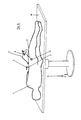
- FIG. 2 shows a pelvic positioner
- FIG. 3 shows the pelvic positioner of FIG. 2 from above with a bubble level.
- FIG. 4 shows the pelvic positioner of FIG. 2 being placed close to a pelvis.
- FIG. 5 shows the guide of FIG. 1 in use.
- FIG. 6 is an enlarged view of the guide of FIG. 1 in use.
- FIG. 7 illustrates the different operating actions when using the guide of FIG. 1 .
- FIG. 8 is an exploded view of a calibrating apparatus.
- FIG. 9 shows the calibrating apparatus of FIG. 8 in use with the guide of FIG. 1 .
- FIG. 10 shows a pelvic orientation witness without its bubble level.
- FIG. 11 shows a pelvic orientation witness linked to a pelvic fixator.
- FIG. 12 shows a guide and an instrument separated from each other.
- FIG. 13 shows the guide and the instrument of FIG. 12 fixed to each other.
- FIG. 14 illustrates the way to position the guide with respect to the ASIS.
- FIG. 15 shows the relation between the guide, instrument and the pelvic orientation witness.
- the orientation device shown in FIG. 1A is a guide 2 and comprises a frame 35 , a fixing means 11 which are adapted to be fixed to an acetabular prosthetic cup instrument 4 (see also FIGS. 5 , 6 , 7 , 9 , 12 and 13 ), and a guide shaft 8 with pointers at its free end.
- Bubble levels 6 consisting of one right 9 and one left 10 indicators, are fixed to the fixing means 11 .
- the bubble level orientation can be adapted (calibrated) by deformation of the bubble level support.
- the pointers 12 help to align the guide shaft 8 with the ASIS 7 (see FIGS. 5 , 6 and 14 ).
- a laser pointer 38 is substituted for pointers 12 .
- the laser pointer 38 produces a laser beam which the operator points at the ASIS 7 .
- FIGS. 2 to 4 show a pelvic positioner 17 made of frame 39 having an adjustable support 18 incorporating a two-dimensional bubble level 19 and two bars 20 having at their free end pelvic feelers 22 .
- the bubble level 19 helps to position the pelvis in strict lateral decubitus using as a reference the antero superior iliac spines (ASIS) and the direction of the force of gravity Fg.
- ASIS antero superior iliac spines
- the bars 20 must come into contact with ASIS 7 through palpation with, for example, middle and annular fingers, which allows identification of the pelvic position.
- a pad 40 on an end thereof provides a reference surface which, when placed against the plane of the operating table 41 ensures perpendicular orientation therewith.
- FIG. 5 shows a patient in strict lateral decubitus.
- the correct orientation of the guide 2 is obtained when the bubble level 10 is at zero.
- the pelvic orientation is permanently checked with another embodiment of the invention, an orientation witness 3 (see also FIG. 6 ), made of bubble level 16 linked to a fixator 15 fixed to the iliac crest 13 .
- the fixator 15 may be made of a “SHANZ” pin and clamp of a “HOFFMANN II”TM hand external fixator, allowing fixation to the iliac crest 13 via a Shanz Pin (commercially available).
- the right 9 and left 10 indicators precisely identify the direction of the force of gravity Fg giving the adequate orientation in abduction and anteversion previously calibrated at manufacture or by the surgeon taking into account two points reference. Thanks to these two points, e.g. ASIS 7 and the instrument shaft free end, the flexion/extension of the pelvis the “Pitch” is taken into account.
- FIG. 6 more clearly shows the orientation of the pelvis 13 in lateral decubitus. It represents an axial view showing anteversion of the cup 14 .
- FIG. 7 indicates the different operating steps when using the guide 2 .
- A Control of the pelvic orientation in real time.
- the desired orientation of the guide 2 is obtained with the callibrating apparatus illustrated in FIGS. 8 and 9 .
- the bubble level 6 can be bent (made of bendable material) centering the bubble and thus recording the desired orientation.
- Desired anteversion 32 or “recorded” anteversion is read off these edges.
- Desired abduction 33 or recorded abduction is read off these edges.
- the distance between the forks can be altered so as to calibrate for the specific angle of the patient (i.e. the angle between the HJC and the pubis at the ASIS). It should be noted at this point that this angle may change from 33 to 41 degrees from one patient to the other.
- FIG. 10 shows a pelvic orientation witness 3 made of a planar support and a shaft.
- the planar support has two flexible elements which are adapted to hold a bubble level in a similar way as shown on FIG. 3 .
- the orientation witness 3 (see FIG. 11 ) is pivotally linked to a fixator 15 which has a free end adapted for being fixed to the pelvis.
- the embodiment of the invention which is a guide which attaches to a surgical instrument, is used in the following manner:
- the present invention offers several advantages.
- the invention helps control the desired orientation of the pelvis in strict lateral decubitus or strict dorsal decubitus hence controlling the pelvic position in the three planes at the time of cup insertion.
- the invention provides ease of use without requiring the surgeon to look at the guide from a specific point of view. Seeing the bubble or bulls' eye level is enough to determine the orientation.
- the invention is low cost and little training is required, making it available to surgeons even in developing countries.
- the invention is useful in minimally invasive surgery techniques MIS.
- the invention allows the surgeon to calibrate his instrument to the desired orientation (abduction and anteversion).
- the invention allows orientation of acetabular cups already in situ can be reliably measured with the guide.
- the invention is adaptable to existing ancillary and current surgical techniques in dorsal decubitus, lateral decubitus, cemented, uncemented, anterolateral or posterolateral approaches.
- the invention can be adapted so as to point at a reference point associated with the patient, such as a point on a device which mounts on the patient (thereby, indirectly pointing at a point on a patient).
Landscapes
- Health & Medical Sciences (AREA)
- Life Sciences & Earth Sciences (AREA)
- Surgery (AREA)
- Orthopedic Medicine & Surgery (AREA)
- Veterinary Medicine (AREA)
- General Health & Medical Sciences (AREA)
- Oral & Maxillofacial Surgery (AREA)
- Engineering & Computer Science (AREA)
- Biomedical Technology (AREA)
- Heart & Thoracic Surgery (AREA)
- Transplantation (AREA)
- Public Health (AREA)
- Animal Behavior & Ethology (AREA)
- Nuclear Medicine, Radiotherapy & Molecular Imaging (AREA)
- Molecular Biology (AREA)
- Dentistry (AREA)
- Biophysics (AREA)
- Physical Education & Sports Medicine (AREA)
- Medical Informatics (AREA)
- Cardiology (AREA)
- Vascular Medicine (AREA)
- Prostheses (AREA)
- Surgical Instruments (AREA)
Abstract
Description
-
- Observer variability
- Subject variability (Differences among patients)
- Instrument variability
-
- instrument fixing means for fixing the orientation device to the instrument,
- linear pointing means for pointing at least one reference point fixed to a patient, the reference point may be either an anatomical reference or a marker fixed to a specific part of the patient,
- orientation means.
-
- Instrument Variability (guide used)
- Differences resulting from the instrument used.
- Eye coordination in two different planes
- Does not take into account pitch angle for axis of anteversion (but orientation of the table)
- Use of a mechanical guide that can not be calibrated with a gold standard.
-
- Standardising the methods for placement of the femoral and acetabular components by increasing objectivity.
- Training the surgeons in the standard techniques: Guide with Gravity Assisted Navigation System facilitates and improves training of surgeons.
- Improve patient positioning: Guide with Gravity Assisted Navigation System facilitates and improves patient positioning.
- Refining the instruments used for orientation of the components: making it easier to use allowing use by looking at it from different angles.
- Automating the instrument (avoid human error)
- Repeating the measurement
-
- Standardising the methods in an operations manual.
- Training the surgeons in the standard (i.e reproducible) techniques.
- Improve patient positioning
- Refining the instruments used for orientation of the components.
- Automating the instruments
- Calibration of the instruments and the “position of the patient” (WITH A GOLD STANDARD)
-
- 1. Patient in strict lateral decubitus
- 2. Orientation device/guide
- 3. Orientation device/witness
- 4. Acetabular prosthetic cup instrument
- 5. Acetabulum
- 6. Guide bubble levels
- 7. ASIS
- 8. Guide shaft
- 9. Right indicator
- 10. Left indicator
- 11. Fixing means
- 12. Pointer
- 13. Pelvis/iliac crest
- 14. Prosthetic cup
- 15. Pelvic witness fixator/frame
- 16. Pelvic witness orientation means
- 17. Pelvic positioner
- 18. Support
- 19. Pelvic positioner orientation means
- 20. Bar
- 21. Length adjusting means
- 22. Pelvic feeler
- Calibrating apparatus
- 24. Basis
- 25. Bubble level
- 26. Height adjusters
- 27. Scale for measuring anteversion mounted on a Gimbal mechanism
- 28. Calibration fork for right hip
- 29. Calibration fork for left hip
- 30. Axis of rotation for the anteversion
- 31. Scale for abduction
- 32. Axis of rotation for abduction
- 33. Abduction and anteversion to be read off the edges of the disk
- 34. Threaded hole for fixing cup positioner
- 35. Frame of Guide
- 36. Thread/implement fixing means
- 37. Surgical instrument
- 38. Laser pointer
- 39. Frame of pelvic positioner
- 40. Pad of pelvic positioner (to rest on operating table)
- 41. Operating table (plane)
-
- 1—Install the patient 1 in strict lateral decubitus and fix the pelvis 13 in the usual fashion with the pubic and sacral supports.
- 2—Control that the
ASIS 7 are parallel to the direction of the force of gravity Fg with pelvic positioner 17 (seeFIG. 4 ). This controls the initial position of the pelvis 13 in “Roll” and “Yaw”. - 3—Proceed to disinfection and draping of the extremity. Through a two centimeter skin incision over the iliac crest, implant a
Shanz pin 15. - 4—Using a clamp from a Hoffman II external hand fixator, set to zero the orientation witness or any other clamping device. The pin must be blocked to the iliac crest to void rotation. 3. These will allow resetting of the pelvis 13 to the initial desired position with respect to the direction of the force of gravity Fg at key intervals during surgery, such as acetabular reaming and cup impaction (see
FIG. 14 ). This avoids the possibility of correct positioning with respect to direction of the force of gravity Fg but erroneous with respect to the pelvis 13. - 5—Continue with an usual surgical technique until the last reaming. Check that the pelvis 13 is in the initial desired position by looking at the orientation witness 3 (see
FIG. 15 ) and correct if necessary by moving the pelvis 13 until the bubble is set to zero. - 6—For a factory pre calibrated guide, place the
last reamer 37 inside the acetabulum, place thepointer 12 over the easilypalpable ASIS 7, move theguide 2 until the bubble is centered identifying with precision the direction of the force of gravity Fg. - 7—Run the reamer in that position to obtain a cavity in the precalibrated orientation (Abduction and Anteversion).
- 8—To place the final cup 14, adapt the
guide 2 and thecup positioner 4, repeatstep 5 and then 6. - 9—To measure the cup 14 orientation in a patient, adapt the
cup positioner 4 to the cup 14, check that the pelvis 13 is adequately oriented with theorientation witness 3 and correct if necessary. Align thepointer 12 with theASIS 7 and bend the support of thebubble level 6 until the bubble is centered identifying with precision the direction of the force of gravity Fg. - 10—Screw the
cup positioner 4 and theguide 2 on to the calibrating apparatus 23. - 11—Move both
elements pointer 12 over one of theforks ASIS 7 location and read from thedisc
Claims (21)
Applications Claiming Priority (3)
| Application Number | Priority Date | Filing Date | Title |
|---|---|---|---|
| CH0300502 | 2003-07-24 | ||
| WOPCT/CH03/00502 | 2003-07-24 | ||
| PCT/CH2004/000466 WO2005009303A1 (en) | 2003-07-24 | 2004-07-23 | Orientation device for surgical implement |
Publications (2)
| Publication Number | Publication Date |
|---|---|
| US20060184177A1 US20060184177A1 (en) | 2006-08-17 |
| US8764758B2 true US8764758B2 (en) | 2014-07-01 |
Family
ID=34085297
Family Applications (1)
| Application Number | Title | Priority Date | Filing Date |
|---|---|---|---|
| US10/565,002 Expired - Fee Related US8764758B2 (en) | 2003-07-24 | 2004-07-23 | Orientation device for surgical implement |
Country Status (4)
| Country | Link |
|---|---|
| US (1) | US8764758B2 (en) |
| EP (1) | EP1651151B1 (en) |
| JP (1) | JP4865550B2 (en) |
| WO (1) | WO2005009303A1 (en) |
Cited By (18)
| Publication number | Priority date | Publication date | Assignee | Title |
|---|---|---|---|---|
| US20130261632A1 (en) * | 2012-03-29 | 2013-10-03 | Carl F. Livorsi | Surgical instrument and method of positioning an acetabular prosthetic component |
| US20140094925A1 (en) * | 2012-09-29 | 2014-04-03 | Rodney E. Satterthwaite | Surgical instrument and method of positioning an acetabular prosthetic component |
| US9056020B1 (en) * | 2014-07-08 | 2015-06-16 | Zafer Termanini | Acetabular cup device and method thereof |
| US9192392B2 (en) | 2008-07-24 | 2015-11-24 | OrthAlign, Inc. | Systems and methods for joint replacement |
| US9295566B2 (en) | 2010-05-04 | 2016-03-29 | Depuy International Limited | Alignment guide |
| US20160206331A1 (en) * | 2001-05-25 | 2016-07-21 | Conformis, Inc. | Patient Selectable Joint Arthroplasty Devices and Surgical Tools |
| US9549742B2 (en) | 2012-05-18 | 2017-01-24 | OrthAlign, Inc. | Devices and methods for knee arthroplasty |
| US9603722B2 (en) | 2009-05-05 | 2017-03-28 | Depuy International Limited | Alignment guide |
| US9649160B2 (en) | 2012-08-14 | 2017-05-16 | OrthAlign, Inc. | Hip replacement navigation system and method |
| US9693879B2 (en) | 2010-05-04 | 2017-07-04 | Depuy International Limited | Alignment guide with spirit level |
| US9775725B2 (en) | 2009-07-24 | 2017-10-03 | OrthAlign, Inc. | Systems and methods for joint replacement |
| US9931059B2 (en) | 2008-09-10 | 2018-04-03 | OrthAlign, Inc. | Hip surgery systems and methods |
| US10363149B2 (en) | 2015-02-20 | 2019-07-30 | OrthAlign, Inc. | Hip replacement navigation system and method |
| US10543097B2 (en) | 2012-09-20 | 2020-01-28 | Depuy Ireland Unlimited Company | Method and surgical instrument system with multiple lengths of broaches sharing a common geometry |
| US10863995B2 (en) | 2017-03-14 | 2020-12-15 | OrthAlign, Inc. | Soft tissue measurement and balancing systems and methods |
| US10869771B2 (en) | 2009-07-24 | 2020-12-22 | OrthAlign, Inc. | Systems and methods for joint replacement |
| US10918499B2 (en) | 2017-03-14 | 2021-02-16 | OrthAlign, Inc. | Hip replacement navigation systems and methods |
| US11179167B2 (en) | 2003-06-09 | 2021-11-23 | OrthAlign, Inc. | Surgical orientation system and method |
Families Citing this family (126)
| Publication number | Priority date | Publication date | Assignee | Title |
|---|---|---|---|---|
| DE10200690B4 (en) * | 2002-01-10 | 2005-03-03 | Intraplant Ag | Aid for implantation of a hip joint endoprosthesis |
| US8057482B2 (en) | 2003-06-09 | 2011-11-15 | OrthAlign, Inc. | Surgical orientation device and method |
| US7862570B2 (en) | 2003-10-03 | 2011-01-04 | Smith & Nephew, Inc. | Surgical positioners |
| US7764985B2 (en) | 2003-10-20 | 2010-07-27 | Smith & Nephew, Inc. | Surgical navigation system component fault interfaces and related processes |
| EA008902B1 (en) * | 2003-11-12 | 2007-08-31 | Интернэшнл Пэйтент Оунерз (Кайман) Лимитед | A gauge for use in a surgical procedure |
| US7794467B2 (en) | 2003-11-14 | 2010-09-14 | Smith & Nephew, Inc. | Adjustable surgical cutting systems |
| EP1737375B1 (en) | 2004-04-21 | 2021-08-11 | Smith & Nephew, Inc | Computer-aided navigation systems for shoulder arthroplasty |
| US7494489B2 (en) | 2004-05-07 | 2009-02-24 | Jeffrey S. Roh | Systems and methods that facilitate minimally invasive spine surgery |
| US20060190011A1 (en) * | 2004-12-02 | 2006-08-24 | Michael Ries | Systems and methods for providing a reference plane for mounting an acetabular cup during a computer-aided surgery |
| US8979853B2 (en) * | 2005-02-17 | 2015-03-17 | Lucas Anissian | Method and system for determining resection guidelines for joint replacement surgical procedures |
| US8177788B2 (en) | 2005-02-22 | 2012-05-15 | Smith & Nephew, Inc. | In-line milling system |
| KR100706030B1 (en) * | 2005-04-12 | 2007-04-11 | 한국과학기술원 | Navigation system for hip replacement surgery having reference device and method using the same |
| DE102005028831A1 (en) * | 2005-06-15 | 2006-12-28 | Aesculap Ag & Co. Kg | Method and surgical navigation system for producing a receiving cavity for an acetabular cup |
| CA2640265A1 (en) * | 2006-01-31 | 2007-08-09 | Robert Lye | Positioning bracket |
| US8535387B2 (en) | 2006-02-27 | 2013-09-17 | Biomet Manufacturing, Llc | Patient-specific tools and implants |
| US8282646B2 (en) | 2006-02-27 | 2012-10-09 | Biomet Manufacturing Corp. | Patient specific knee alignment guide and associated method |
| US8568487B2 (en) | 2006-02-27 | 2013-10-29 | Biomet Manufacturing, Llc | Patient-specific hip joint devices |
| US8092465B2 (en) | 2006-06-09 | 2012-01-10 | Biomet Manufacturing Corp. | Patient specific knee alignment guide and associated method |
| US9907659B2 (en) | 2007-04-17 | 2018-03-06 | Biomet Manufacturing, Llc | Method and apparatus for manufacturing an implant |
| US10278711B2 (en) | 2006-02-27 | 2019-05-07 | Biomet Manufacturing, Llc | Patient-specific femoral guide |
| US8608748B2 (en) | 2006-02-27 | 2013-12-17 | Biomet Manufacturing, Llc | Patient specific guides |
| US8864769B2 (en) | 2006-02-27 | 2014-10-21 | Biomet Manufacturing, Llc | Alignment guides with patient-specific anchoring elements |
| US8070752B2 (en) | 2006-02-27 | 2011-12-06 | Biomet Manufacturing Corp. | Patient specific alignment guide and inter-operative adjustment |
| US20150335438A1 (en) | 2006-02-27 | 2015-11-26 | Biomet Manufacturing, Llc. | Patient-specific augments |
| US8133234B2 (en) | 2006-02-27 | 2012-03-13 | Biomet Manufacturing Corp. | Patient specific acetabular guide and method |
| US9173661B2 (en) | 2006-02-27 | 2015-11-03 | Biomet Manufacturing, Llc | Patient specific alignment guide with cutting surface and laser indicator |
| US9113971B2 (en) | 2006-02-27 | 2015-08-25 | Biomet Manufacturing, Llc | Femoral acetabular impingement guide |
| US9339278B2 (en) | 2006-02-27 | 2016-05-17 | Biomet Manufacturing, Llc | Patient-specific acetabular guides and associated instruments |
| US8591516B2 (en) | 2006-02-27 | 2013-11-26 | Biomet Manufacturing, Llc | Patient-specific orthopedic instruments |
| US9918740B2 (en) | 2006-02-27 | 2018-03-20 | Biomet Manufacturing, Llc | Backup surgical instrument system and method |
| US8473305B2 (en) | 2007-04-17 | 2013-06-25 | Biomet Manufacturing Corp. | Method and apparatus for manufacturing an implant |
| US9345548B2 (en) | 2006-02-27 | 2016-05-24 | Biomet Manufacturing, Llc | Patient-specific pre-operative planning |
| US8298237B2 (en) | 2006-06-09 | 2012-10-30 | Biomet Manufacturing Corp. | Patient-specific alignment guide for multiple incisions |
| US8377066B2 (en) | 2006-02-27 | 2013-02-19 | Biomet Manufacturing Corp. | Patient-specific elbow guides and associated methods |
| US8407067B2 (en) | 2007-04-17 | 2013-03-26 | Biomet Manufacturing Corp. | Method and apparatus for manufacturing an implant |
| US7967868B2 (en) | 2007-04-17 | 2011-06-28 | Biomet Manufacturing Corp. | Patient-modified implant and associated method |
| US8608749B2 (en) | 2006-02-27 | 2013-12-17 | Biomet Manufacturing, Llc | Patient-specific acetabular guides and associated instruments |
| US8603180B2 (en) | 2006-02-27 | 2013-12-10 | Biomet Manufacturing, Llc | Patient-specific acetabular alignment guides |
| US9289253B2 (en) | 2006-02-27 | 2016-03-22 | Biomet Manufacturing, Llc | Patient-specific shoulder guide |
| US8858561B2 (en) | 2006-06-09 | 2014-10-14 | Blomet Manufacturing, LLC | Patient-specific alignment guide |
| US8241293B2 (en) | 2006-02-27 | 2012-08-14 | Biomet Manufacturing Corp. | Patient specific high tibia osteotomy |
| US7819879B2 (en) * | 2006-04-21 | 2010-10-26 | Wright Medical Technology, Inc. | Guide pin placement for hip resurfacing |
| US9795399B2 (en) | 2006-06-09 | 2017-10-24 | Biomet Manufacturing, Llc | Patient-specific knee alignment guide and associated method |
| US8002799B2 (en) * | 2006-07-21 | 2011-08-23 | Spinefrontier Lls | System and method for spine fixation |
| WO2008073999A2 (en) * | 2006-12-12 | 2008-06-19 | Vladimir Alexander | Laser assisted total joint arthroplasty |
| US8734452B2 (en) * | 2006-12-15 | 2014-05-27 | Spinefrontier, Inc | Guidance system,tools and devices for spinal fixation |
| GB2448740B (en) * | 2007-04-26 | 2012-03-14 | Derek James Wallace Mcminn | Alignment device |
| US8265949B2 (en) | 2007-09-27 | 2012-09-11 | Depuy Products, Inc. | Customized patient surgical plan |
| US8357111B2 (en) | 2007-09-30 | 2013-01-22 | Depuy Products, Inc. | Method and system for designing patient-specific orthopaedic surgical instruments |
| CN102652687B (en) | 2007-09-30 | 2015-08-19 | 德普伊产品公司 | The patient-specific orthopaedic surgical instrumentation of customization |
| US10335236B1 (en) | 2007-11-01 | 2019-07-02 | Stephen B. Murphy | Surgical system using a registration device |
| US8267938B2 (en) | 2007-11-01 | 2012-09-18 | Murphy Stephen B | Method and apparatus for determining acetabular component positioning |
| US8986309B1 (en) | 2007-11-01 | 2015-03-24 | Stephen B. Murphy | Acetabular template component and method of using same during hip arthrosplasty |
| DK2361045T3 (en) * | 2008-09-17 | 2021-05-25 | Gyder Surgical Pty Ltd | SURGICAL ORIENTATION SYSTEM |
| NO329062B1 (en) * | 2008-11-14 | 2010-08-09 | Karete Hoiberg Johansen | Apparatus and method for testing muscular capacity |
| GB2465750A (en) * | 2008-11-26 | 2010-06-02 | Depuy Int Ltd | Prosthesis positioning system |
| GB0900830D0 (en) * | 2009-01-20 | 2009-03-04 | Depuy Int Ltd | Orientation guide |
| US8170641B2 (en) | 2009-02-20 | 2012-05-01 | Biomet Manufacturing Corp. | Method of imaging an extremity of a patient |
| WO2010145769A1 (en) * | 2009-06-17 | 2010-12-23 | Universität Bern | Methods and devices for patient-specific acetabular component alignment in total hip arthroplasty |
| DE102009028503B4 (en) | 2009-08-13 | 2013-11-14 | Biomet Manufacturing Corp. | Resection template for the resection of bones, method for producing such a resection template and operation set for performing knee joint surgery |
| EP2501313A1 (en) * | 2009-11-17 | 2012-09-26 | Queen's University At Kingston | Patient-specific guide for acetabular cup placement |
| US8709016B2 (en) * | 2009-12-11 | 2014-04-29 | Curexo Technology Corporation | Surgical guide system using an active robot arm |
| WO2012082164A1 (en) | 2010-01-21 | 2012-06-21 | Orthallgn, Inc. | Systems and methods for joint replacement |
| US8632547B2 (en) | 2010-02-26 | 2014-01-21 | Biomet Sports Medicine, Llc | Patient-specific osteotomy devices and methods |
| US9066727B2 (en) | 2010-03-04 | 2015-06-30 | Materialise Nv | Patient-specific computed tomography guides |
| CN103096839A (en) | 2010-06-03 | 2013-05-08 | 史密夫和内修有限公司 | Orthopaedic implants |
| US8956393B2 (en) * | 2010-07-06 | 2015-02-17 | Luis Edgardo Ramos Maza | Devices, systems, and methods for acetabulum repair |
| US9271744B2 (en) | 2010-09-29 | 2016-03-01 | Biomet Manufacturing, Llc | Patient-specific guide for partial acetabular socket replacement |
| US9968376B2 (en) | 2010-11-29 | 2018-05-15 | Biomet Manufacturing, Llc | Patient-specific orthopedic instruments |
| US8890511B2 (en) | 2011-01-25 | 2014-11-18 | Smith & Nephew, Inc. | Targeting operation sites |
| US9241745B2 (en) | 2011-03-07 | 2016-01-26 | Biomet Manufacturing, Llc | Patient-specific femoral version guide |
| US8715289B2 (en) | 2011-04-15 | 2014-05-06 | Biomet Manufacturing, Llc | Patient-specific numerically controlled instrument |
| US9675400B2 (en) | 2011-04-19 | 2017-06-13 | Biomet Manufacturing, Llc | Patient-specific fracture fixation instrumentation and method |
| US8668700B2 (en) | 2011-04-29 | 2014-03-11 | Biomet Manufacturing, Llc | Patient-specific convertible guides |
| US8956364B2 (en) | 2011-04-29 | 2015-02-17 | Biomet Manufacturing, Llc | Patient-specific partial knee guides and other instruments |
| JP2012231988A (en) * | 2011-05-02 | 2012-11-29 | Yoshio Koga | Support implement during artificial hip cup surgery |
| CN102283689B (en) * | 2011-05-26 | 2013-03-20 | 祝桂涛 | Guiding device for artificial hip joint replacement acetabular rasp |
| US8532807B2 (en) | 2011-06-06 | 2013-09-10 | Biomet Manufacturing, Llc | Pre-operative planning and manufacturing method for orthopedic procedure |
| US9084618B2 (en) | 2011-06-13 | 2015-07-21 | Biomet Manufacturing, Llc | Drill guides for confirming alignment of patient-specific alignment guides |
| AU2012270983B2 (en) | 2011-06-16 | 2016-09-22 | Smith & Nephew, Inc. | Surgical alignment using references |
| WO2012176054A1 (en) | 2011-06-22 | 2012-12-27 | Medacta International S.A. | Device for patellar resurfacing |
| US20130001121A1 (en) | 2011-07-01 | 2013-01-03 | Biomet Manufacturing Corp. | Backup kit for a patient-specific arthroplasty kit assembly |
| US8764760B2 (en) | 2011-07-01 | 2014-07-01 | Biomet Manufacturing, Llc | Patient-specific bone-cutting guidance instruments and methods |
| US8597365B2 (en) | 2011-08-04 | 2013-12-03 | Biomet Manufacturing, Llc | Patient-specific pelvic implants for acetabular reconstruction |
| US9295497B2 (en) | 2011-08-31 | 2016-03-29 | Biomet Manufacturing, Llc | Patient-specific sacroiliac and pedicle guides |
| US9066734B2 (en) | 2011-08-31 | 2015-06-30 | Biomet Manufacturing, Llc | Patient-specific sacroiliac guides and associated methods |
| US9386993B2 (en) | 2011-09-29 | 2016-07-12 | Biomet Manufacturing, Llc | Patient-specific femoroacetabular impingement instruments and methods |
| KR20130046336A (en) | 2011-10-27 | 2013-05-07 | 삼성전자주식회사 | Multi-view device of display apparatus and contol method thereof, and display system |
| US9301812B2 (en) | 2011-10-27 | 2016-04-05 | Biomet Manufacturing, Llc | Methods for patient-specific shoulder arthroplasty |
| US9451973B2 (en) | 2011-10-27 | 2016-09-27 | Biomet Manufacturing, Llc | Patient specific glenoid guide |
| ES2635542T3 (en) | 2011-10-27 | 2017-10-04 | Biomet Manufacturing, Llc | Glenoid guides specific to the patient |
| US9554910B2 (en) | 2011-10-27 | 2017-01-31 | Biomet Manufacturing, Llc | Patient-specific glenoid guide and implants |
| US9237950B2 (en) | 2012-02-02 | 2016-01-19 | Biomet Manufacturing, Llc | Implant with patient-specific porous structure |
| AU2013204941B2 (en) | 2012-06-28 | 2015-10-01 | Gyder Surgical Pty Ltd | A Referencing Apparatus and Associated Methods |
| JP2014097220A (en) * | 2012-11-15 | 2014-05-29 | Toshiba Corp | Surgical operation support device |
| US9204977B2 (en) | 2012-12-11 | 2015-12-08 | Biomet Manufacturing, Llc | Patient-specific acetabular guide for anterior approach |
| US9060788B2 (en) | 2012-12-11 | 2015-06-23 | Biomet Manufacturing, Llc | Patient-specific acetabular guide for anterior approach |
| US9839438B2 (en) | 2013-03-11 | 2017-12-12 | Biomet Manufacturing, Llc | Patient-specific glenoid guide with a reusable guide holder |
| US9579107B2 (en) | 2013-03-12 | 2017-02-28 | Biomet Manufacturing, Llc | Multi-point fit for patient specific guide |
| US9498233B2 (en) | 2013-03-13 | 2016-11-22 | Biomet Manufacturing, Llc. | Universal acetabular guide and associated hardware |
| US9826981B2 (en) | 2013-03-13 | 2017-11-28 | Biomet Manufacturing, Llc | Tangential fit of patient-specific guides |
| US9585768B2 (en) * | 2013-03-15 | 2017-03-07 | DePuy Synthes Products, Inc. | Acetabular cup prosthesis alignment system and method |
| US9517145B2 (en) | 2013-03-15 | 2016-12-13 | Biomet Manufacturing, Llc | Guide alignment system and method |
| WO2014161574A1 (en) | 2013-04-03 | 2014-10-09 | Brainlab Ag | Method and device for determining the orientation of a co-ordinate system of an anatomical object in a global co-ordinate system |
| CN105246433B (en) | 2013-06-11 | 2018-06-05 | 奥尔索夫特公司 | Acetabular cup prosthesis locating apparatus and method |
| US20150112349A1 (en) | 2013-10-21 | 2015-04-23 | Biomet Manufacturing, Llc | Ligament Guide Registration |
| US10282488B2 (en) | 2014-04-25 | 2019-05-07 | Biomet Manufacturing, Llc | HTO guide with optional guided ACL/PCL tunnels |
| US9408616B2 (en) | 2014-05-12 | 2016-08-09 | Biomet Manufacturing, Llc | Humeral cut guide |
| US9561040B2 (en) | 2014-06-03 | 2017-02-07 | Biomet Manufacturing, Llc | Patient-specific glenoid depth control |
| US9839436B2 (en) | 2014-06-03 | 2017-12-12 | Biomet Manufacturing, Llc | Patient-specific glenoid depth control |
| US10070873B2 (en) | 2014-06-30 | 2018-09-11 | Tornier, Inc. | Device for maintaining alignment of a cannulated shaft over a guide pin |
| US9826994B2 (en) | 2014-09-29 | 2017-11-28 | Biomet Manufacturing, Llc | Adjustable glenoid pin insertion guide |
| US9833245B2 (en) | 2014-09-29 | 2017-12-05 | Biomet Sports Medicine, Llc | Tibial tubercule osteotomy |
| US10195054B1 (en) | 2014-12-02 | 2019-02-05 | Dartmouth-Hitchcock Clinic | Acetabular cup alignment system |
| US9820868B2 (en) | 2015-03-30 | 2017-11-21 | Biomet Manufacturing, Llc | Method and apparatus for a pin apparatus |
| US10568647B2 (en) | 2015-06-25 | 2020-02-25 | Biomet Manufacturing, Llc | Patient-specific humeral guide designs |
| US10226262B2 (en) | 2015-06-25 | 2019-03-12 | Biomet Manufacturing, Llc | Patient-specific humeral guide designs |
| US10327861B2 (en) | 2015-10-22 | 2019-06-25 | Straight Shot, LLC | Surgical implant alignment device |
| JP6401205B2 (en) * | 2016-04-28 | 2018-10-03 | 学校法人北里研究所 | Leg length measuring device and leg length measuring method |
| KR101806801B1 (en) * | 2016-06-20 | 2017-12-08 | 인제대학교 산학협력단 | Cutting blocks and keel groove guide for knee arthroplasty |
| GB201613337D0 (en) * | 2016-08-02 | 2016-09-14 | Clarke Susannah G And Embody Orthopaedic Ltd | Hip cup alignment guide |
| US10722310B2 (en) | 2017-03-13 | 2020-07-28 | Zimmer Biomet CMF and Thoracic, LLC | Virtual surgery planning system and method |
| KR102019889B1 (en) | 2017-08-24 | 2019-09-10 | 주식회사 코렌텍 | Smart surgical instruments for artificial joint replacement |
| US10639079B2 (en) | 2017-10-24 | 2020-05-05 | Straight Shot, LLC | Surgical implant alignment device |
| US11051829B2 (en) | 2018-06-26 | 2021-07-06 | DePuy Synthes Products, Inc. | Customized patient-specific orthopaedic surgical instrument |
| KR102186308B1 (en) * | 2019-01-28 | 2020-12-03 | 주식회사 코렌텍 | Smart surgical instruments for artificial joint replacement |
Citations (14)
| Publication number | Priority date | Publication date | Assignee | Title |
|---|---|---|---|---|
| US4393599A (en) * | 1980-09-02 | 1983-07-19 | John W. Sterrenberg | Leveling mechanisms for hand-held power drill |
| US4893619A (en) * | 1988-02-04 | 1990-01-16 | Intermedics Orthopedics, Inc. | Humeral osteotomy guide |
| GB2224937A (en) | 1988-09-14 | 1990-05-23 | Malcolm Hugh Farmer | The alignment of hip joint sockets in hip joint replacement |
| US5030221A (en) * | 1989-12-13 | 1991-07-09 | Buechel Frederick F | Prosthesis holding system |
| US5141512A (en) * | 1989-08-28 | 1992-08-25 | Farmer Malcolm H | Alignment of hip joint sockets in hip joint replacement |
| WO1997029698A1 (en) | 1996-02-13 | 1997-08-21 | Advanced Technical Fabrication | Hip prosthesis positioning instrument |
| US5700268A (en) * | 1997-01-06 | 1997-12-23 | Zimmer, Inc. | Device for measuring leg length and off-set for a total hip replacement |
| DE20006515U1 (en) | 2000-04-08 | 2000-08-10 | Gobit Gmbh | Tool for inserting an element into the human body |
| US6302890B1 (en) | 2000-03-16 | 2001-10-16 | Leone Innovations Corporation | Pelvic alignment assembly |
| US6375395B1 (en) * | 1999-07-30 | 2002-04-23 | Michael G. Heintzeman | Laser guide for hand held power drill |
| US6395005B1 (en) * | 2000-04-14 | 2002-05-28 | Howmedica Osteonics Corp. | Acetabular alignment apparatus and method |
| WO2002067784A2 (en) | 2001-02-27 | 2002-09-06 | Smith & Nephew, Inc. | Surgical navigation systems and processes for unicompartmental knee |
| WO2002071987A1 (en) | 2001-03-13 | 2002-09-19 | Iversen Bjoern Franc | Method and device for providing of information after insertion of a prosthesis in a hip-joint |
| US6743235B2 (en) * | 2002-10-15 | 2004-06-01 | Goli V. Subba Rao | Modular instrument for positioning acetabular prosthetic socket |
-
2004
- 2004-07-23 EP EP04738106A patent/EP1651151B1/en not_active Not-in-force
- 2004-07-23 JP JP2006520648A patent/JP4865550B2/en not_active Expired - Fee Related
- 2004-07-23 WO PCT/CH2004/000466 patent/WO2005009303A1/en active Search and Examination
- 2004-07-23 US US10/565,002 patent/US8764758B2/en not_active Expired - Fee Related
Patent Citations (15)
| Publication number | Priority date | Publication date | Assignee | Title |
|---|---|---|---|---|
| US4393599A (en) * | 1980-09-02 | 1983-07-19 | John W. Sterrenberg | Leveling mechanisms for hand-held power drill |
| US4893619A (en) * | 1988-02-04 | 1990-01-16 | Intermedics Orthopedics, Inc. | Humeral osteotomy guide |
| GB2224937A (en) | 1988-09-14 | 1990-05-23 | Malcolm Hugh Farmer | The alignment of hip joint sockets in hip joint replacement |
| US5141512A (en) * | 1989-08-28 | 1992-08-25 | Farmer Malcolm H | Alignment of hip joint sockets in hip joint replacement |
| US5030221A (en) * | 1989-12-13 | 1991-07-09 | Buechel Frederick F | Prosthesis holding system |
| US6102915A (en) | 1996-02-13 | 2000-08-15 | Advanced Technical Fabrication | Hip prosthesis positioning instrument |
| WO1997029698A1 (en) | 1996-02-13 | 1997-08-21 | Advanced Technical Fabrication | Hip prosthesis positioning instrument |
| US5700268A (en) * | 1997-01-06 | 1997-12-23 | Zimmer, Inc. | Device for measuring leg length and off-set for a total hip replacement |
| US6375395B1 (en) * | 1999-07-30 | 2002-04-23 | Michael G. Heintzeman | Laser guide for hand held power drill |
| US6302890B1 (en) | 2000-03-16 | 2001-10-16 | Leone Innovations Corporation | Pelvic alignment assembly |
| DE20006515U1 (en) | 2000-04-08 | 2000-08-10 | Gobit Gmbh | Tool for inserting an element into the human body |
| US6395005B1 (en) * | 2000-04-14 | 2002-05-28 | Howmedica Osteonics Corp. | Acetabular alignment apparatus and method |
| WO2002067784A2 (en) | 2001-02-27 | 2002-09-06 | Smith & Nephew, Inc. | Surgical navigation systems and processes for unicompartmental knee |
| WO2002071987A1 (en) | 2001-03-13 | 2002-09-19 | Iversen Bjoern Franc | Method and device for providing of information after insertion of a prosthesis in a hip-joint |
| US6743235B2 (en) * | 2002-10-15 | 2004-06-01 | Goli V. Subba Rao | Modular instrument for positioning acetabular prosthetic socket |
Non-Patent Citations (1)
| Title |
|---|
| Japanese Office Action mailed Sep. 14, 2010 from Japanese Patent Application No. 2006-520648, and its English translation. |
Cited By (46)
| Publication number | Priority date | Publication date | Assignee | Title |
|---|---|---|---|---|
| US20160206331A1 (en) * | 2001-05-25 | 2016-07-21 | Conformis, Inc. | Patient Selectable Joint Arthroplasty Devices and Surgical Tools |
| US11903597B2 (en) | 2003-06-09 | 2024-02-20 | OrthAlign, Inc. | Surgical orientation system and method |
| US11179167B2 (en) | 2003-06-09 | 2021-11-23 | OrthAlign, Inc. | Surgical orientation system and method |
| US9855075B2 (en) | 2008-07-24 | 2018-01-02 | OrthAlign, Inc. | Systems and methods for joint replacement |
| US11871965B2 (en) | 2008-07-24 | 2024-01-16 | OrthAlign, Inc. | Systems and methods for joint replacement |
| US11684392B2 (en) | 2008-07-24 | 2023-06-27 | OrthAlign, Inc. | Systems and methods for joint replacement |
| US9192392B2 (en) | 2008-07-24 | 2015-11-24 | OrthAlign, Inc. | Systems and methods for joint replacement |
| US11547451B2 (en) | 2008-07-24 | 2023-01-10 | OrthAlign, Inc. | Systems and methods for joint replacement |
| US10864019B2 (en) | 2008-07-24 | 2020-12-15 | OrthAlign, Inc. | Systems and methods for joint replacement |
| US10206714B2 (en) | 2008-07-24 | 2019-02-19 | OrthAlign, Inc. | Systems and methods for joint replacement |
| US9572586B2 (en) | 2008-07-24 | 2017-02-21 | OrthAlign, Inc. | Systems and methods for joint replacement |
| US10321852B2 (en) | 2008-09-10 | 2019-06-18 | OrthAlign, Inc. | Hip surgery systems and methods |
| US11179062B2 (en) | 2008-09-10 | 2021-11-23 | OrthAlign, Inc. | Hip surgery systems and methods |
| US11540746B2 (en) | 2008-09-10 | 2023-01-03 | OrthAlign, Inc. | Hip surgery systems and methods |
| US9931059B2 (en) | 2008-09-10 | 2018-04-03 | OrthAlign, Inc. | Hip surgery systems and methods |
| US9603722B2 (en) | 2009-05-05 | 2017-03-28 | Depuy International Limited | Alignment guide |
| US9775725B2 (en) | 2009-07-24 | 2017-10-03 | OrthAlign, Inc. | Systems and methods for joint replacement |
| US10869771B2 (en) | 2009-07-24 | 2020-12-22 | OrthAlign, Inc. | Systems and methods for joint replacement |
| US10238510B2 (en) | 2009-07-24 | 2019-03-26 | OrthAlign, Inc. | Systems and methods for joint replacement |
| US11633293B2 (en) | 2009-07-24 | 2023-04-25 | OrthAlign, Inc. | Systems and methods for joint replacement |
| US9693879B2 (en) | 2010-05-04 | 2017-07-04 | Depuy International Limited | Alignment guide with spirit level |
| US9295566B2 (en) | 2010-05-04 | 2016-03-29 | Depuy International Limited | Alignment guide |
| US20130261632A1 (en) * | 2012-03-29 | 2013-10-03 | Carl F. Livorsi | Surgical instrument and method of positioning an acetabular prosthetic component |
| US10285826B2 (en) | 2012-03-29 | 2019-05-14 | DePuy Synthes Products, Inc. | Surgical instrument and method of positioning an acetabular prosthetic component |
| US9358130B2 (en) * | 2012-03-29 | 2016-06-07 | DePuy Synthes Products, Inc. | Surgical instrument and method of positioning an acetabular prosthetic component |
| US10716580B2 (en) | 2012-05-18 | 2020-07-21 | OrthAlign, Inc. | Devices and methods for knee arthroplasty |
| US9549742B2 (en) | 2012-05-18 | 2017-01-24 | OrthAlign, Inc. | Devices and methods for knee arthroplasty |
| US10603115B2 (en) | 2012-08-14 | 2020-03-31 | OrthAlign, Inc. | Hip replacement navigation system and method |
| US9649160B2 (en) | 2012-08-14 | 2017-05-16 | OrthAlign, Inc. | Hip replacement navigation system and method |
| US11653981B2 (en) | 2012-08-14 | 2023-05-23 | OrthAlign, Inc. | Hip replacement navigation system and method |
| US11911119B2 (en) | 2012-08-14 | 2024-02-27 | OrthAlign, Inc. | Hip replacement navigation system and method |
| US11648127B2 (en) | 2012-09-20 | 2023-05-16 | Depuy Ireland Unlimited Company | Method and system including sleeves and broaches for surgically preparing the patient's bone |
| US10543097B2 (en) | 2012-09-20 | 2020-01-28 | Depuy Ireland Unlimited Company | Method and surgical instrument system with multiple lengths of broaches sharing a common geometry |
| US10583011B2 (en) | 2012-09-20 | 2020-03-10 | Depuy Ireland Unlimited Company | Method and system including sleeves and broaches for surgically preparing the patient's bone |
| US9427333B2 (en) | 2012-09-29 | 2016-08-30 | DePuy Synthes Products, Inc. | Surgical instrument and method of positioning an acetabular prosthetic component |
| US10137008B2 (en) | 2012-09-29 | 2018-11-27 | Depuy Ireland Unlimited Company | Surgical instrument and method of positioning an acetabular prosthetic component |
| US9055975B2 (en) * | 2012-09-29 | 2015-06-16 | DePuy Synthes Products, Inc. | Surgical instrument and method of positioning an acetabular prosthetic component |
| US20140094925A1 (en) * | 2012-09-29 | 2014-04-03 | Rodney E. Satterthwaite | Surgical instrument and method of positioning an acetabular prosthetic component |
| US9737416B2 (en) | 2012-09-29 | 2017-08-22 | DePuy Synthes Products, Inc. | Surgical instrument and method of positioning an acetabular prosthetic component |
| US9056020B1 (en) * | 2014-07-08 | 2015-06-16 | Zafer Termanini | Acetabular cup device and method thereof |
| US11020245B2 (en) | 2015-02-20 | 2021-06-01 | OrthAlign, Inc. | Hip replacement navigation system and method |
| US10363149B2 (en) | 2015-02-20 | 2019-07-30 | OrthAlign, Inc. | Hip replacement navigation system and method |
| US11547580B2 (en) | 2017-03-14 | 2023-01-10 | OrthAlign, Inc. | Hip replacement navigation systems and methods |
| US10918499B2 (en) | 2017-03-14 | 2021-02-16 | OrthAlign, Inc. | Hip replacement navigation systems and methods |
| US10863995B2 (en) | 2017-03-14 | 2020-12-15 | OrthAlign, Inc. | Soft tissue measurement and balancing systems and methods |
| US11786261B2 (en) | 2017-03-14 | 2023-10-17 | OrthAlign, Inc. | Soft tissue measurement and balancing systems and methods |
Also Published As
| Publication number | Publication date |
|---|---|
| JP2006528496A (en) | 2006-12-21 |
| EP1651151B1 (en) | 2012-06-06 |
| WO2005009303A1 (en) | 2005-02-03 |
| EP1651151A1 (en) | 2006-05-03 |
| US20060184177A1 (en) | 2006-08-17 |
| JP4865550B2 (en) | 2012-02-01 |
Similar Documents
| Publication | Publication Date | Title |
|---|---|---|
| US8764758B2 (en) | Orientation device for surgical implement | |
| US9603722B2 (en) | Alignment guide | |
| AU2002246466B2 (en) | Computer assisted insertion of an artifical hip joint | |
| JP2930314B2 (en) | Computer-assisted surgical medical device | |
| US8548559B2 (en) | Method and apparatus for computer-assisted femoral head resurfacing | |
| EP2294980B1 (en) | Hip surgery assembly | |
| US20140303631A1 (en) | Method and apparatus for determining the orientation and/or position of an object during a medical procedure | |
| EP3383284B1 (en) | Alignment device | |
| US20130053858A1 (en) | Precise hip component positioning for hip replacement surgery | |
| AU2002246466A1 (en) | Computer assisted insertion of an artifical hip joint | |
| KR20140128939A (en) | system and method for precise prosthesis positioning in hip arthroplasty | |
| US20060074353A1 (en) | Glenoid instrumentation and associated method | |
| WO2009062314A1 (en) | Leg alignment and length measurement in hip replacement surgery | |
| JP2007503289A (en) | Surgical orientation machine and method | |
| JP2008532707A (en) | Medical fixing member placement system | |
| CN213607210U (en) | Angle measuring device for acetabulum prosthesis personalized assembly of hip joint replacement operation | |
| CN115315223A (en) | Reference device |
Legal Events
| Date | Code | Title | Description |
|---|---|---|---|
| AS | Assignment |
Owner name: SAN-TECH SURGICAL SARL, SWITZERLAND Free format text: ASSIGNMENT OF ASSIGNORS INTEREST;ASSIGNOR:ECHEVERRI, SANTIAGO;REEL/FRAME:017470/0921 Effective date: 20051228 |
|
| FEPP | Fee payment procedure |
Free format text: PAYOR NUMBER ASSIGNED (ORIGINAL EVENT CODE: ASPN); ENTITY STATUS OF PATENT OWNER: SMALL ENTITY |
|
| STCF | Information on status: patent grant |
Free format text: PATENTED CASE |
|
| MAFP | Maintenance fee payment |
Free format text: PAYMENT OF MAINTENANCE FEE, 4TH YR, SMALL ENTITY (ORIGINAL EVENT CODE: M2551) Year of fee payment: 4 |
|
| FEPP | Fee payment procedure |
Free format text: MAINTENANCE FEE REMINDER MAILED (ORIGINAL EVENT CODE: REM.); ENTITY STATUS OF PATENT OWNER: SMALL ENTITY |
|
| LAPS | Lapse for failure to pay maintenance fees |
Free format text: PATENT EXPIRED FOR FAILURE TO PAY MAINTENANCE FEES (ORIGINAL EVENT CODE: EXP.); ENTITY STATUS OF PATENT OWNER: SMALL ENTITY |
|
| STCH | Information on status: patent discontinuation |
Free format text: PATENT EXPIRED DUE TO NONPAYMENT OF MAINTENANCE FEES UNDER 37 CFR 1.362 |
|
| FP | Lapsed due to failure to pay maintenance fee |
Effective date: 20220701 |