US8663073B1 - Portable punching bag apparatus - Google Patents
Portable punching bag apparatus Download PDFInfo
- Publication number
- US8663073B1 US8663073B1 US13/344,800 US201213344800A US8663073B1 US 8663073 B1 US8663073 B1 US 8663073B1 US 201213344800 A US201213344800 A US 201213344800A US 8663073 B1 US8663073 B1 US 8663073B1
- Authority
- US
- United States
- Prior art keywords
- doorway
- support plate
- bar
- molding
- engaging
- Prior art date
- Legal status (The legal status is an assumption and is not a legal conclusion. Google has not performed a legal analysis and makes no representation as to the accuracy of the status listed.)
- Expired - Fee Related, expires
Links
Images


Classifications
-
- A—HUMAN NECESSITIES
- A63—SPORTS; GAMES; AMUSEMENTS
- A63B—APPARATUS FOR PHYSICAL TRAINING, GYMNASTICS, SWIMMING, CLIMBING, OR FENCING; BALL GAMES; TRAINING EQUIPMENT
- A63B69/00—Training appliances or apparatus for special sports
- A63B69/20—Punching balls, e.g. for boxing; Other devices for striking used during training of combat sports, e.g. bags
- A63B69/22—Punching balls, e.g. for boxing; Other devices for striking used during training of combat sports, e.g. bags mounted on, or suspended from, a fixed support
- A63B69/222—Punching balls, e.g. for boxing; Other devices for striking used during training of combat sports, e.g. bags mounted on, or suspended from, a fixed support suspended from a fixed support
-
- A—HUMAN NECESSITIES
- A63—SPORTS; GAMES; AMUSEMENTS
- A63B—APPARATUS FOR PHYSICAL TRAINING, GYMNASTICS, SWIMMING, CLIMBING, OR FENCING; BALL GAMES; TRAINING EQUIPMENT
- A63B21/00—Exercising apparatus for developing or strengthening the muscles or joints of the body by working against a counterforce, with or without measuring devices
- A63B21/16—Supports for anchoring force-resisters
- A63B21/1618—Supports for anchoring force-resisters on a door or a door frame
- A63B21/1663—Supports for anchoring force-resisters on a door or a door frame for anchoring between a door and the door frame
-
- A—HUMAN NECESSITIES
- A63—SPORTS; GAMES; AMUSEMENTS
- A63B—APPARATUS FOR PHYSICAL TRAINING, GYMNASTICS, SWIMMING, CLIMBING, OR FENCING; BALL GAMES; TRAINING EQUIPMENT
- A63B2210/00—Space saving
- A63B2210/50—Size reducing arrangements for stowing or transport
Definitions
- This invention relates generally to exercise equipment, and more particularly to a portable punching bag apparatus which is easily transportable and attachable to any conventional doorway framework having door moldings.
- exercise and body conditioning equipment continues to grow as an industry, providing the end user with an ever broadening variety of exercise equipment which may be used in a home setting or have portability which facilitates convenient transport of such exercise equipment. Additionally, exercise equipment has become more user-friendly in that very little space for ancillary support structure or attachment thereto is required for convenience of use.
- the present invention provides a portable punching bag apparatus which is easily attachable within any doorway having conventional moldings therearound.
- the apparatus may be left in place for use for an extended period of time, or may be easily removed during periods of non-use and disassembled by simply removing the punching bag and carrying the remaining mounting structure of the apparatus in a carrying bag or by other convenient transfer means.
- This invention is directed to a portable punching bag apparatus including a support plate sized in width to fit within a doorway.
- a punching bag is supported centrally of a lower surface of the support plate while a doorway contact bar is connected to support plate, each end of the contact bar extending beyond the side margins of the support plate, the length of the contact bar being greater than the width of the doorway.
- a door molding engaging bar is also connected to the support plate parallel to the contact bar and positioned above the support plate a distance sufficient to rest atop a top molding of the doorway whereby the apparatus is supported by the engaging bar against an upper edge of the top molding.
- a clamp support is connected to and extends above the support plate.
- An elongated clamp rod is selectively movably held by the clamp support for tightening against a wall surface above a top of the doorway on an opposite side of the wall from the engaging bar whereby the apparatus is removably securable for use beneath the top of the doorway.
- Still another object of this invention is to provide a punching bag apparatus which, after being attached to the top of a doorway frame for use, may be easily removed and stored.
- Another object of this invention is to provide an economical punching bag apparatus which will easily attach to a doorway framework without the necessity for either tools or fasteners of any sort.
- FIG. 1 is a perspective of the apparatus in place ready for use within a doorway.
- FIG. 2 is another perspective view of the apparatus of FIG. 1 .
- FIG. 3 is a perspective of the apparatus.
- FIG. 4 is another perspective view of the apparatus.
- FIG. 5 is a side elevation view of the apparatus showing the doorway and doorway moldings in phantom.
- FIG. 6 is a left end elevation view of FIG. 5 .
- FIG. 7 is top plan view of FIG. 5 .
- FIG. 8 is a bottom plan view of FIG. 5 .
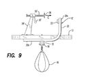
- FIG. 9 is a side elevation view of an alternate and preferred embodiment of the invention.
- the apparatus 10 in the in-use position within a doorway D in FIGS. 1 and 2 .
- the apparatus 10 includes a flat support plate 12 formed of laminated wood, molded plastic material or other suitable material and having a width somewhat narrower than the width of a conventional doorway D.
- the apparatus 10 In the in-use position, the apparatus 10 is positioned just below the top T of the doorway D so that the punching bag 16 held on a bag support 18 will be positioned at about user eye level.
- an elongated doorway contact bar 14 is securely attached to, and extends across the width of the support plate 12 beneath the mid-portion of the bottom surface of the support plate 12 .
- the overall length of the contact bar 14 is substantially greater than the width of the doorway D so that non-marring covers 32 over the distal portion of each end of the contact bar 14 will be positioned against the side moldings M s of the doorway D.
- Two spaced apart doorway molding engaging bar supports 20 are fastened by mechanical fasteners along each side edge of the support plate 12 .
- the upright leg 20 a is positioned through notches cut into the side margins of the support plate 12 as shown.
- Extending between and attached to the upper distal ends of the upright support legs 20 a is an elongated door molding engaging bar 22 .
- This engaging bar 22 is positioned transversely to the length of the support plate 12 and spaced thereabove a distance, as best seen in FIG. 5 , so as to be engageable against the upper margin of a top doorway molding M t which is permanently attached to the doorway along the top T of the doorway D.
- the punching bag 16 is connected to a bag support 18 which, in turn, is rigidly or permanently connected to, and hangs downwardly from, the contact bar 14 .
- a clamp arrangement includes a clamp support 24 which is connected along the longitudinal center line of the upper surface of the support plate 12 as best seen in FIGS. 3 and 5 .
- This clamp support 24 includes a threaded aperture having an axis aligned above and parallel to the support plate 12 .
- This threaded aperture supports an elongated threaded clamp rod 26 which is rotatably movable axially by a clamp tightening handle 30 by rotation back and forth in the direction of arrow A, causing a corresponding longitudinal movement in the direction of arrow B of a wall engaging disc 28 attached to the distal end of the threaded clamp rod 26 .
- the apparatus 10 is positionable within the doorway D and the between doorway sides S beneath the top T of the doorway with the support plate 12 positioned just below the lower surface of the top T such that the door molding engaging bar 22 rests atop the upper margin of the top molding M t attached on one side of the wall W.
- the tightening handle 30 is rotated so as to move the wall engaging disc 28 so as to make contact with the opposite side of the wall W above the opposite top molding M t .
- the apparatus 10 is manually leveled and, when the tightening process is complete, the apparatus 10 is held securely within the position shown with the punching bag 16 at an eye-level orientation ready for use.
- FIG. 9 an alternate and preferred embodiment of the clamp arrangement is there shown.
- the clamp support 24 ′ is attached by mechanical fasteners to the top surface of the support plate 12 .
- a squeezable tightening handle 30 ′ Securely disposed at the upper distal end of the clamp support 24 ′ is a squeezable tightening handle 30 ′ which, when hand-squeezed together, extends the clamp rod 26 ′ in the direction of arrow C.
- This arrangement similar to that of a caulking gun, will effect more expedited installation and removal and is the preferred embodiment for this apparatus 10 ′.
Abstract
Description
- 10. punching bag apparatus
- 12. support plate
- 14. doorway contact bar
- 16. punching bag
- 18. bag support
- 20. doorway molding engaging bar support
- 22. doorway molding engaging bar
- 24. clamp support
- 24′. clamp support
- 26. clamp rod
- 26′. clamp rod
- 28. wall engaging disc
- 30. clamp tightening handle
- 30′. clamp tightening handle
- 32. cover
Claims (3)
Priority Applications (1)
| Application Number | Priority Date | Filing Date | Title |
|---|---|---|---|
| US13/344,800 US8663073B1 (en) | 2012-01-06 | 2012-01-06 | Portable punching bag apparatus |
Applications Claiming Priority (1)
| Application Number | Priority Date | Filing Date | Title |
|---|---|---|---|
| US13/344,800 US8663073B1 (en) | 2012-01-06 | 2012-01-06 | Portable punching bag apparatus |
Publications (1)
| Publication Number | Publication Date |
|---|---|
| US8663073B1 true US8663073B1 (en) | 2014-03-04 |
Family
ID=50158704
Family Applications (1)
| Application Number | Title | Priority Date | Filing Date |
|---|---|---|---|
| US13/344,800 Expired - Fee Related US8663073B1 (en) | 2012-01-06 | 2012-01-06 | Portable punching bag apparatus |
Country Status (1)
| Country | Link |
|---|---|
| US (1) | US8663073B1 (en) |
Cited By (4)
| Publication number | Priority date | Publication date | Assignee | Title |
|---|---|---|---|---|
| WO2015070350A1 (en) * | 2013-11-18 | 2015-05-21 | Avantgarde Sport Inc. | Method of manufacturing an exercise punching ball |
| US20150165295A1 (en) * | 2013-11-27 | 2015-06-18 | Christopher Rea | Portable Speed Bag Retention Mechanism |
| USD784472S1 (en) | 2014-08-07 | 2017-04-18 | Taylor Made Group, Inc. | Water filled punching bag |
| US11389706B2 (en) * | 2016-10-06 | 2022-07-19 | Fighter Foundry Llc | Striking apparatus and configurations thereof |
Citations (8)
| Publication number | Priority date | Publication date | Assignee | Title |
|---|---|---|---|---|
| US4787626A (en) * | 1986-07-03 | 1988-11-29 | Timothy Gallagher | Sit-up support device |
| US5634873A (en) * | 1994-09-08 | 1997-06-03 | Strong River Corporation | Hamstring stretching device and method |
| US5720702A (en) * | 1996-09-27 | 1998-02-24 | Lee; Sunny | Resilient exercise device |
| US5824966A (en) * | 1997-10-22 | 1998-10-20 | Bacou Usa Safety, Inc. | Enhanced band earplug |
| US6013014A (en) * | 1999-01-12 | 2000-01-11 | Hern; James L. | Couch exercise apparatus |
| US6059698A (en) * | 1997-06-12 | 2000-05-09 | Rob Mazor | Exercise device for removable mounting on a door |
| US7223219B2 (en) * | 2004-03-30 | 2007-05-29 | Arvin Floyd Liester | Frictional variable resistance exercise device |
| US20070149369A1 (en) * | 2005-12-28 | 2007-06-28 | Finch Stephen B | Hanging fitness device for abdominals |
-
2012
- 2012-01-06 US US13/344,800 patent/US8663073B1/en not_active Expired - Fee Related
Patent Citations (8)
| Publication number | Priority date | Publication date | Assignee | Title |
|---|---|---|---|---|
| US4787626A (en) * | 1986-07-03 | 1988-11-29 | Timothy Gallagher | Sit-up support device |
| US5634873A (en) * | 1994-09-08 | 1997-06-03 | Strong River Corporation | Hamstring stretching device and method |
| US5720702A (en) * | 1996-09-27 | 1998-02-24 | Lee; Sunny | Resilient exercise device |
| US6059698A (en) * | 1997-06-12 | 2000-05-09 | Rob Mazor | Exercise device for removable mounting on a door |
| US5824966A (en) * | 1997-10-22 | 1998-10-20 | Bacou Usa Safety, Inc. | Enhanced band earplug |
| US6013014A (en) * | 1999-01-12 | 2000-01-11 | Hern; James L. | Couch exercise apparatus |
| US7223219B2 (en) * | 2004-03-30 | 2007-05-29 | Arvin Floyd Liester | Frictional variable resistance exercise device |
| US20070149369A1 (en) * | 2005-12-28 | 2007-06-28 | Finch Stephen B | Hanging fitness device for abdominals |
Cited By (8)
| Publication number | Priority date | Publication date | Assignee | Title |
|---|---|---|---|---|
| WO2015070350A1 (en) * | 2013-11-18 | 2015-05-21 | Avantgarde Sport Inc. | Method of manufacturing an exercise punching ball |
| US10220284B2 (en) | 2013-11-18 | 2019-03-05 | Avantgarde Sport Inc. | Punching ball |
| US10981044B2 (en) | 2013-11-18 | 2021-04-20 | Avantgarde Sport Inc. | Method of training with an exercise punching ball |
| US20150165295A1 (en) * | 2013-11-27 | 2015-06-18 | Christopher Rea | Portable Speed Bag Retention Mechanism |
| US9358441B2 (en) * | 2013-11-27 | 2016-06-07 | Christopher Rea | Portable speed bag retention mechanism |
| USD784472S1 (en) | 2014-08-07 | 2017-04-18 | Taylor Made Group, Inc. | Water filled punching bag |
| USD789471S1 (en) | 2014-08-07 | 2017-06-13 | Taylor Made Group, Llc | Water filled punching bag |
| US11389706B2 (en) * | 2016-10-06 | 2022-07-19 | Fighter Foundry Llc | Striking apparatus and configurations thereof |
Similar Documents
| Publication | Publication Date | Title |
|---|---|---|
| US8663073B1 (en) | Portable punching bag apparatus | |
| US6508743B1 (en) | Collapsible doorway exercise apparatus | |
| US7404531B2 (en) | Trash bag holder with handle | |
| US7833131B2 (en) | Rebounder exercise system | |
| US9186552B1 (en) | Multiuse treadmill apparatus | |
| US20130244836A1 (en) | Door Frame Mounted Exercise Device And System | |
| US9283460B1 (en) | Training apparatus for stationary bicycle rollers | |
| US8137250B1 (en) | Abdominal exercising apparatus | |
| US5928092A (en) | Batting tee for baseball and softball | |
| US20110172068A1 (en) | Resistance training device | |
| US8136458B1 (en) | Clothesline apparatus | |
| US20080312051A1 (en) | Wall mountable exercise assembly | |
| US6286803B1 (en) | Device to assist in proper picture hanging | |
| US9457252B2 (en) | Baseball practice device | |
| US9333615B1 (en) | Apparatus for mounting one or more orbital sanders having an extended handle | |
| US20150345163A1 (en) | Adjustable Support Member for a Spa Cover Lifting Device | |
| US20140094350A1 (en) | Punching bag support apparatus | |
| US7261631B1 (en) | Portable big game hoist assembly | |
| US9586080B2 (en) | Weighted barbell stand | |
| US11389706B2 (en) | Striking apparatus and configurations thereof | |
| US6412741B1 (en) | Beverage holding device with railing attachment | |
| US3947010A (en) | Service clamp | |
| US6129220A (en) | Multi-station organizer and sports bottle holder | |
| US10398958B2 (en) | Striking apparatus and configurations thereof | |
| US6425562B1 (en) | Golf club washer mounting apparatus |
Legal Events
| Date | Code | Title | Description |
|---|---|---|---|
| STCF | Information on status: patent grant |
Free format text: PATENTED CASE |
|
| AS | Assignment |
Owner name: W.D.K. VENTURES LLC, FLORIDA Free format text: LICENSE;ASSIGNOR:HAYS, NICHOLAS;REEL/FRAME:039427/0486 Effective date: 20160707 |
|
| AS | Assignment |
Owner name: W.D.K. VENTURES LLC, FLORIDA Free format text: AMENDMENT;ASSIGNOR:HAYS, NICHOLAS;REEL/FRAME:042571/0135 Effective date: 20170217 |
|
| FEPP | Fee payment procedure |
Free format text: MAINTENANCE FEE REMINDER MAILED (ORIGINAL EVENT CODE: REM.) |
|
| FEPP | Fee payment procedure |
Free format text: SURCHARGE FOR LATE PAYMENT, SMALL ENTITY (ORIGINAL EVENT CODE: M2554) |
|
| MAFP | Maintenance fee payment |
Free format text: PAYMENT OF MAINTENANCE FEE, 4TH YR, SMALL ENTITY (ORIGINAL EVENT CODE: M2551) Year of fee payment: 4 |
|
| AS | Assignment |
Owner name: HAYS, NICHOLAS, FLORIDA Free format text: ASSIGNMENT OF ASSIGNORS INTEREST;ASSIGNOR:W.D.K. VENTURES LLC;REEL/FRAME:046130/0005 Effective date: 20180619 |
|
| FEPP | Fee payment procedure |
Free format text: MAINTENANCE FEE REMINDER MAILED (ORIGINAL EVENT CODE: REM.); ENTITY STATUS OF PATENT OWNER: SMALL ENTITY |
|
| LAPS | Lapse for failure to pay maintenance fees |
Free format text: PATENT EXPIRED FOR FAILURE TO PAY MAINTENANCE FEES (ORIGINAL EVENT CODE: EXP.); ENTITY STATUS OF PATENT OWNER: SMALL ENTITY |
|
| STCH | Information on status: patent discontinuation |
Free format text: PATENT EXPIRED DUE TO NONPAYMENT OF MAINTENANCE FEES UNDER 37 CFR 1.362 |
|
| FP | Lapsed due to failure to pay maintenance fee |
Effective date: 20220304 |