US8643944B2 - Infrared zooming lens - Google Patents
Infrared zooming lens Download PDFInfo
- Publication number
- US8643944B2 US8643944B2 US13/039,626 US201113039626A US8643944B2 US 8643944 B2 US8643944 B2 US 8643944B2 US 201113039626 A US201113039626 A US 201113039626A US 8643944 B2 US8643944 B2 US 8643944B2
- Authority
- US
- United States
- Prior art keywords
- lens
- zoom lens
- infrared zoom
- lens group
- infrared
- Prior art date
- Legal status (The legal status is an assumption and is not a legal conclusion. Google has not performed a legal analysis and makes no representation as to the accuracy of the status listed.)
- Active, expires
Links
- 229910052732 germanium Inorganic materials 0.000 claims abstract description 53
- GNPVGFCGXDBREM-UHFFFAOYSA-N germanium atom Chemical compound [Ge] GNPVGFCGXDBREM-UHFFFAOYSA-N 0.000 claims abstract description 53
- 238000003384 imaging method Methods 0.000 claims description 4
- 230000005499 meniscus Effects 0.000 claims description 4
- 230000004075 alteration Effects 0.000 abstract description 57
- 230000003287 optical effect Effects 0.000 abstract description 29
- 102100022108 Aspartyl/asparaginyl beta-hydroxylase Human genes 0.000 description 44
- 101000901030 Homo sapiens Aspartyl/asparaginyl beta-hydroxylase Proteins 0.000 description 44
- 201000009310 astigmatism Diseases 0.000 description 17
- 238000010586 diagram Methods 0.000 description 9
- 239000000126 substance Substances 0.000 description 9
- 239000005083 Zinc sulfide Substances 0.000 description 4
- 229910052984 zinc sulfide Inorganic materials 0.000 description 4
- DRDVZXDWVBGGMH-UHFFFAOYSA-N zinc;sulfide Chemical compound [S-2].[Zn+2] DRDVZXDWVBGGMH-UHFFFAOYSA-N 0.000 description 4
- 238000002835 absorbance Methods 0.000 description 2
- 230000003292 diminished effect Effects 0.000 description 2
- 230000002401 inhibitory effect Effects 0.000 description 2
- 238000012423 maintenance Methods 0.000 description 1
- 238000004519 manufacturing process Methods 0.000 description 1
- 238000000465 moulding Methods 0.000 description 1
- 238000005498 polishing Methods 0.000 description 1
- 230000003068 static effect Effects 0.000 description 1
Images


Classifications
-
- G—PHYSICS
- G02—OPTICS
- G02B—OPTICAL ELEMENTS, SYSTEMS OR APPARATUS
- G02B13/00—Optical objectives specially designed for the purposes specified below
- G02B13/14—Optical objectives specially designed for the purposes specified below for use with infrared or ultraviolet radiation
-
- G—PHYSICS
- G02—OPTICS
- G02B—OPTICAL ELEMENTS, SYSTEMS OR APPARATUS
- G02B15/00—Optical objectives with means for varying the magnification
- G02B15/14—Optical objectives with means for varying the magnification by axial movement of one or more lenses or groups of lenses relative to the image plane for continuously varying the equivalent focal length of the objective
- G02B15/144—Optical objectives with means for varying the magnification by axial movement of one or more lenses or groups of lenses relative to the image plane for continuously varying the equivalent focal length of the objective having four groups only
- G02B15/1441—Optical objectives with means for varying the magnification by axial movement of one or more lenses or groups of lenses relative to the image plane for continuously varying the equivalent focal length of the objective having four groups only the first group being positive
- G02B15/144113—Optical objectives with means for varying the magnification by axial movement of one or more lenses or groups of lenses relative to the image plane for continuously varying the equivalent focal length of the objective having four groups only the first group being positive arranged +-++
-
- G—PHYSICS
- G02—OPTICS
- G02B—OPTICAL ELEMENTS, SYSTEMS OR APPARATUS
- G02B13/00—Optical objectives specially designed for the purposes specified below
- G02B13/001—Miniaturised objectives for electronic devices, e.g. portable telephones, webcams, PDAs, small digital cameras
- G02B13/008—Miniaturised objectives for electronic devices, e.g. portable telephones, webcams, PDAs, small digital cameras designed for infrared light
-
- G—PHYSICS
- G02—OPTICS
- G02B—OPTICAL ELEMENTS, SYSTEMS OR APPARATUS
- G02B13/00—Optical objectives specially designed for the purposes specified below
- G02B13/18—Optical objectives specially designed for the purposes specified below with lenses having one or more non-spherical faces, e.g. for reducing geometrical aberration
-
- G—PHYSICS
- G02—OPTICS
- G02B—OPTICAL ELEMENTS, SYSTEMS OR APPARATUS
- G02B15/00—Optical objectives with means for varying the magnification
- G02B15/14—Optical objectives with means for varying the magnification by axial movement of one or more lenses or groups of lenses relative to the image plane for continuously varying the equivalent focal length of the objective
-
- G—PHYSICS
- G02—OPTICS
- G02B—OPTICAL ELEMENTS, SYSTEMS OR APPARATUS
- G02B9/00—Optical objectives characterised both by the number of the components and their arrangements according to their sign, i.e. + or -
- G02B9/34—Optical objectives characterised both by the number of the components and their arrangements according to their sign, i.e. + or - having four components only
Landscapes
- Physics & Mathematics (AREA)
- General Physics & Mathematics (AREA)
- Optics & Photonics (AREA)
- Health & Medical Sciences (AREA)
- Toxicology (AREA)
- Lenses (AREA)
Abstract
The present invention is directed to an infrared zoom lens that consists merely of optical components of germanium so as to implement an optical system that is capable of reducing variation in brightness during varying a magnification rate and is quite bright and that facilitates compensating for aberration, especially spherical aberration that is generally hard to do, thereby producing a clear and vivid image. The infrared zoom lens comprises first to fourth groups of lens pieces arranged in series from the foremost position closest to the object; each of the lens groups having all the lens pieces made of germanium, and at least one of the lens groups consisting simply of a single lens piece.
Description
The present invention relates to an infrared zoom lens of improved ability to compensate for spherical aberration and reduced manufacturing cost.
Prior art infrared zoom lenses include a thermally insulated infrared zoom lens that has optical elements arranged in series from the foremost position closest to the object toward the focal point along the optical axis, namely, first to third lens elements in this sequence where the first lens element has its first and second major surfaces opposed to each other to exhibit positive magnification power, the second lens element has its first and second major surfaces opposed to each other to exhibit negative magnification power, and the third lens element has its first and second major surfaces opposed to each other to exhibit positive magnification power. The first and third lens elements are made of a first substance while the second lens element alone is made of a second substance different from the first substance, and a variation in refractive index of the first substance due to a variation in its temperature (dn/dT) is smaller than that of the second substance, and either one or both of the second major surfaces of the first and third lens elements is formed in diffractive surface (see Patent Document 1 listed below).
Another prior art infrared zoom lens has first to third groups of lens pieces arranged in series from the foremost position closest to the object, and during the zooming, the first and third lens groups are essentially fixed while the second lens group alone are movable where each of the first to third lens groups has at least one lens piece made of zinc sulfide (see Patent Document 2).
Still anther prior art infrared zoom lens is that which incorporates optics dedicated to infrared rays raging 3 to 5 μm or 8 to 12 μm in waveband and which has five groups of lens pieces arranged in series from the foremost position closest to the object, namely, a first lens group consisting of one or two lens pieces to exhibit positive power, a second lens group consisting of one or two lens pieces to exhibit negative power, a third lens group of a single negative meniscus lens having its concave surface positioned closer to the object, a fourth lens group of a single convex lens piece, and a fifth lens group consisting of at least four lens pieces where the rearmost lens piece closest to the imaging field is a positive meniscus lens having its convex major surface faced toward the object; and during the zooming, the first, fourth and fifth lens groups are essentially fixed while the second and third lens groups are movable so that displacing the second lens group along the optical axis permits magnification rate to alter, and meanwhile, displacing the third lens group along the optical axis enables to correct the imaging point under the requirements as defined in the following formulae:
1.00<f 1 /f t
f 2 /f t<−0.40
0.35<f 5 /f t<0.70
where ft is a focal length of the entire optics at the telephoto end, f1 is the focal length of the first lens group, f2 is the focal length of the first lens group, and f5 is the focal length of the fifth lens group (see Patent Document 3).
1.00<f 1 /f t
f 2 /f t<−0.40
0.35<f 5 /f t<0.70
where ft is a focal length of the entire optics at the telephoto end, f1 is the focal length of the first lens group, f2 is the focal length of the first lens group, and f5 is the focal length of the fifth lens group (see Patent Document 3).
-
- Patent Document 1: [0006] Japanese Preliminary Publication of Unexamined Patent Application No. 2005-521918[0007] Patent Document 2: [0008] Japanese Preliminary Publication of Unexamined Patent Application No. 2007-264649[0009] Patent Document 3:
- Japanese Patent No. 3365606
Configured as in Patent Document 1, the infrared zoom lens having its first and third lens elements made of the first substance facilitates maintenance by virtue of simple and manageable storage of the lens substance but is prone to lead to a critical problem that such a zoom lens is troublesome in compensating for aberration. The infrared zoom lens configured as in Patent Document 1 also has a static focal mechanism, which means it conducts no dynamic focusing control and cannot be user friendly.
Configured as in Patent Document 2, the infrared zoom lens has all the lens pieces made of zinc sulfide, which is disadvantageous in that the substance of the lens pieces is expensive and intractable in processing such as molding, polishing, and so forth. In one embodiment of this type of the infrared zoom lens, zinc sulfide is used in combination with germanium. The substance of zinc sulfide which is of low refractive index (approximately 2.2) is disadvantageous in that it brings about difficulty in compensating for aberration.
Configured as in Patent Document 3, the infrared zoom lens incorporates nine to twelve of the lens pieces, which is disadvantageous in that such a zoom lens costs more to fabricate, and that the lens pieces absorb infrared rays more to resultantly produce a darker picture. In addition, because of the larger number of the lens pieces, a lens barrel of such a zoom lens should be more complicated in structure.
The present invention is made to overcome the aforementioned problems in the prior art infrared zoom lenses, and accordingly, it is an object of the present invention to provide the improved infrared zoom lens that consists merely of optical components of germanium so as to implement an optical system that is capable of reducing variation in brightness during varying a magnification rate and is quite bright.
It is another object of the present invention to provide the improved infrared zoom lens that has the reduced number of lens pieces to implement a simple-structure and lightweight lens barrel and that has the lens pieces of the reduced absorbance of infrared rays so as to produce a bright image.
It is further another object of the present invention to provide the improved infrared zoom lens that is capable of compensating for Aberration adequately throughout the zooming range.
In one aspect of the present invention, an infrared zoom lens has first to fourth groups of lens pieces arranged in series from the foremost position closest to the object; each of the lens groups having all the lens pieces made of germanium, and at least one of the lens groups consisting simply of a single lens piece.
In accordance with the present invention, the infrared zoom lens has an optical system that can reduce variation in brightness during varying a magnification rate and is quite bright and that facilitates compensating for aberration, thereby producing a clear and vivid image.
Also, in accordance with the present invention, the infrared zoom lens has the reduced number of lens pieces so as to bring about a simple-structure and lightweight lens barrel, and it has the lens pieces of the reduced absorbance of infrared rays so as to produce a bright image.
Moreover, in accordance with the present invention, the infrared zoom lens is useful to compensate for aberration adequately throughout the zooming range.
The present invention is exemplified in the following manners:
The infrared zoom lens has the first lens group of positive power, the second lens group of negative power, the third lens group of positive power, and the fourth lens group of positive power.
Configured in this manner, the infrared zoom lens advantageously reduces variation in aberration throughout the zooming range.
In another aspect of the present invention, the infrared zoom lens may be adapted to meet requirements as defined in the following formula:
0.8≦f1/ft≦1.7 (1)
where ft is a focal length of the zoom lens at a telephoto setting, and f1 is the focal length of the first lens group.
0.8≦f1/ft≦1.7 (1)
where ft is a focal length of the zoom lens at a telephoto setting, and f1 is the focal length of the first lens group.
The formula (1) provide the requirements to fulfill both the demands of avoiding the entire length of the optics and compensating for aberration. If exceeding the lower limit as defined in the formula (1), the infrared zoom lens has its first lens group intensified in power, which results in spherical aberration being increased at a telephoto setting. On the contrary, if exceeding the upper limit as defined in the formula (1), the infrared zoom lens has its first lens group diminished in power, which leads to a problem that the entire length of the optics should unavoidably increase.
Alternatively, the infrared zoom lens may be adapted to meet requirements as defined in the following formula:
−0.7f2/ft≦−0.1 (2)
where ft is a focal length of the zoom lens at a telephoto setting, and f2 is the focal length of the second lens group.
−0.7f2/ft≦−0.1 (2)
where ft is a focal length of the zoom lens at a telephoto setting, and f2 is the focal length of the second lens group.
The formula (2) provide the requirements to fulfill the demand of inhibiting both variation in aberration during varying a magnification rate and increase in field curvature. If exceeding the upper limit as defined in the formula (2), the infrared zoom lens has its second lens group diminished in power to be insufficient to correct the field curvature. If exceeding the lower limit as defined in the formula (2), the infrared zoom lens has its second lens group intensified in power, which brings about the increased variation in aberration during varying a magnification rate.
Alternatively, the infrared zoom lens may be adapted to meet requirements as defined in the following formula:
1.8≦f3/fw≦4 (3)
where fw is a focal length of the zoom lens at a wide-angle setting, and f3 is the focal length of the third lens group.
1.8≦f3/fw≦4 (3)
where fw is a focal length of the zoom lens at a wide-angle setting, and f3 is the focal length of the third lens group.
The formula (3) provide the requirements to fulfill the demand of adequately compensating for spherical aberration. If exceeding the upper limit as defined in the formula (3), the infrared zoom lens is able to only insufficiently compensate for spherical aberration, which in turn leads to a problem that the entire length of the optics should unavoidably increase. If exceeding the lower limit as defined in the formula (3), the infrared zoom lens excessively compensate for spherical aberration at a wide-angle setting.
In further another aspect of the present invention, the first and third lens groups stay still in their respective fixed positions while the second and fourth lens groups are movable so as to vary a magnification rate.
Configured in this manner, the infrared zoom lens advantageously reduces variation in aberration, especially, field curvature throughout the zooming range.
Further alternatively, the fourth lens group is moved for the focusing.
Configured in this manner, the infrared zoom lens can effectively reduce variation in aberration during the focusing.
Alternatively, the first lens group may consist of a meniscus lens that has its front major surface closer to the object shaped in convex.
Configured in this manner, the infrared zoom lens facilitates an appropriate compensation for spherical aberration and distortion aberration.
Alternatively, the foremost lens piece closest to the object in the second lens group may have its rear major surface facing to the imaging field shaped in concave.
Configured in this manner, the infrared zoom lens facilitates compensating for field curvature.
Alternatively, the first lens group may have its lens piece shaped to have an aspherical surface.
Configured in this manner, the infrared zoom lens facilitates compensating for distortion aberration at a wide-angle setting and for spherical aberration at a telephoto setting.
Alternatively, the second lens group may have one or more of its lens pieces shaped to have an aspherical surface.
Configured in this manner, the infrared zoom lens facilitates both inhibiting variation in aberration as a result of varying a magnification rate and compensating for field curvature.
Alternatively, the third lens group may have one or more of its lens pieces shaped to have an aspherical surface.
Configured in this manner, the infrared zoom lens can effectively compensate for spherical aberration at a wide-angle setting and implement a bright optical system.
Further alternatively, the fourth lens group may have one or more of its lens pieces shaped to have an aspherical surface.
Configured in this manner, the infrared zoom lens facilitates compensation for field curvature and astigmatism and effectively inhibits variation in aberration during the focusing.
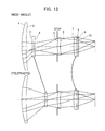
In each optical diagram illustrating the behavior of optical components of an exemplary infrared zoom lens at wide-angle and telephoto settings, respectively, the arrangement of groups of lens pieces at wide-angle or telephoto settings, the center axis through the optics, and light beams incoming and outgoing in and from each lens group at the maximum angles of view are emphasized.
Data on a first preferred embodiment of an infrared zoom lens according to the present invention will be set forth below:
| SURFACE# | | D | GLASS | ||
| 1 | 81.0000 | 5.0000 | GERMANIUM | |||
| 2 | ASPH | 168.0078 | D(2) | |||
| 3 | ASPH | −101.6133 | 2.0000 | GERMANIUM | ||
| 4 | ASPH | 67.9744 | D(4) | |||
| 5 | STOP | 37.8944 | 3.0000 | GERMANIUM | ||
| 6 | ASPH | 51.6729 | D(6) | |||
| 7 | 49.0000 | 3.0000 | GERMANIUM | |||
| 8 | ASPH | 168.5145 | D(8) | |||
| 9 | 0.0000 | 1.0000 | |
|||
| 10 | 0.0000 | D(10) | ||||
D(i) in the table above denotes where the distance between the adjacent lens groups varies as the focal length is varied (i is the number of the rearmost surface in one lens group).
Any of numbers identifying lens surfaces suffixed with characters ASPH designates an aspherical surface. A formula representing the aspherical surface is given as follows:
where H is a height of the aspherical surface from and perpendicular to the optical axis, X(H) is a varied amount of the height H relative to a varied departure with the apex of the aspherical surface at the origin, R is a paraxial radius of curvature, is a conic constant, A is the second order aspheric coefficient, B is the fourth order aspheric coefficient, C is the sixth order aspheric coefficient, D is the eighth order aspheric coefficient, and E is the tenth order aspheric coefficient.
| Data on the Aspherical Surface |
| SURFACE# | 0(EP) | 2(A) | 4(B) | 6(C) | 8(D) | 10(E) |
| 2 | −27.4716 | 0.00000E+000 | 7.71619E−007 | −1.83338E−010 | 0.00000E+000 | 0.00000E+000 |
| 3 | 47.8330 | 0.00000E+000 | 6.27110E−006 | 8.16225E−008 | 0.00000E+000 | 0.00000E+000 |
| 4 | 6.3703 | 0.00000E+000 | −6.48539E−006 | 8.36406E−008 | 0.00000E+000 | 0.00000E+000 |
| 5 | −16.5202 | 0.00000E+000 | 5.79215E−006 | −3.49341E−007 | 0.00000E+000 | 0.00000E+000 |
| 6 | −3.3024 | 0.00000E+000 | −3.40467E−005 | −2.12849E−007 | 0.00000E+000 | 0.00000E+000 |
| 8 | 101.0156 | 0.00000E+000 | 1.44689E−006 | −6.95217E−009 | 0.00000E+000 | 0.00000E+000 |
| Focal Length |
| WIDE-ANGLE | TELEPHOTO | ||
| 14.03 | 40.00 | ||
Distance between the Adjacent Lens Groups during the Zooming
| WIDE-ANGLE | TELEPHOTO | ||
| D(2) | 11.174 | 25.900 | ||
| D(4) | 27.361 | 12.635 | ||
| D(6) | 18.252 | 18.250 | ||
| D(8) | 1.568 | 1.570 | ||
| D(10) | 17.997 | 17.997 | ||
Data on the optical components in a second preferred embodiment of the infrared zoom lens are set forth below:
| SURFACE# | | D | GLASS | ||
| 1 | 217.4855 | 9.0000 | GERMANIUM | |||
| 2 | ASPH | 418.5663 | D(2) | |||
| 3 | ASPH | −240.7084 | 4.5000 | GERMANIUM | ||
| 4 | ASPH | 430.2428 | D(4) | |||
| 5 | STOP | 67.8117 | 7.0000 | GERMANIUM | ||
| 6 | ASPH | 92.1746 | D(6) | |||
| 7 | 37.8153 | 5.0000 | GERMANIUM | |||
| 8 | ASPH | 44.8231 | D(8) | |||
| 9 | 0.0000 | 1.0000 | |
|||
| 10 | 0.0000 | D(10) | ||||
| Data on the Aspherical Surfaces |
| SURFACE# | 0(EP) | 2(A) | 4(B) | 6(C) | 8(D) | 10(E) |
| 2 | 18.5449 | 0.00000E+000 | −3.13306E−008 | −2.42866E−012 | 0.00000E+000 | 0.00000E+000 |
| 3 | −99.0013 | 0.00000E+000 | 6.13608E−007 | −1.92476E−009 | 1.30313E−012 | 0.00000E+000 |
| 4 | 83.4977 | 0.00000E+000 | 1.26877E−006 | −2.48226E−009 | 1.49943E−012 | 0.00000E+000 |
| 5 | −1.1716 | 0.00000E+000 | 1.61863E−007 | 6.75443E−010 | −9.52129E−013 | 0.00000E+000 |
| 6 | 6.2011 | 0.00000E+000 | −1.52912E−006 | 6.19667E−010 | −1.65398E−012 | 0.00000E+000 |
| 8 | 1.2358 | 0.00000E+000 | 1.03673E−007 | 2.58085E−010 | 0.00000E+000 | 0.00000E+000 |
| Focal Length |
| WIDE-ANGLE | TELEPHOTO | ||
| 35.01 | 100.00 | ||
Distance between the Adjacent Lens Groups during the Zooming
| WIDE-ANGLE | TELEPHOTO | ||
| D(2) | 12.500 | 65.536 | ||
| D(4) | 63.036 | 10.000 | ||
| D(6) | 51.580 | 54.574 | ||
| D(8) | 8.8190 | 5.8248 | ||
| D(10) | 18.000 | 18.000 | ||
Data of the optical components of a third preferred embodiment of the infrared zoom lens are set forth below:
| SURFACE# | | D | GLASS | ||
| 1 | 81.0000 | 5.0000 | |
|||
| 2 | 146.8796 | D(2) | ||||
| 3 | ASPH | −116.9334 | 2.0000 | GERMANIUM | ||
| 4 | ASPH | 83.5380 | D(4) | |||
| 5 | STOP | 29.9322 | 3.0000 | GERMANIUM | ||
| 6 | ASPH | 35.9505 | D(6) | |||
| 7 | 49.0000 | 3.0000 | GERMANIUM | |||
| 8 | ASPH | 157.5165 | D(8) | |||
| 9 | 0.0000 | 1.0000 | |
|||
| 10 | 0.0000 | D(10) | ||||
| Data on the Aspherical Surfaces |
| SURFACE# | 0(EP) | 2(A) | 4(B) | 6(C) | 8(D) | 10(E) |
| 3 | 76.4793 | 0.00000E+000 | 2.32912E−005 | 7.25919E−008 | 0.00000E+000 | 0.00000E+000 |
| 4 | −99.0033 | 0.00000E+000 | 3.28211E−005 | 3.72487E−008 | 0.00000E+000 | 0.00000E+000 |
| 5 | −10.9064 | 0.00000E+000 | −8.83597E−006 | −4.11010E−007 | 0.00000E+000 | 0.00000E+000 |
| 6 | −0.4566 | 0.00000E+000 | −7.53352E−005 | −1.59835E−007 | 0.00000E+000 | 0.00000E+000 |
| 8 | 101.0658 | 0.00000E+000 | 3.21451E−006 | −8.01724E−009 | 0.00000E+000 | 0.00000E+000 |
| Focal Length |
| WIDE-ANGLE | TELEPHOTO | ||
| 14.08 | 39.99 | ||
Distance between the Adjacent Lens Groups during the Zooming
| WIDE-ANGLE | TELEPHOTO | ||
| D(2) | 10.706 | 28.286 | ||
| D(4) | 31.224 | 13.645 | ||
| D(6) | 15.628 | 15.623 | ||
| D(8) | 1.411 | 1.416 | ||
| D(10) | 17.996 | 17.996 | ||
Data on the optical components in a fourth preferred embodiment are set forth below:
| SURFACE# | | D | GLASS | ||
| 1 | ASPH | 104.8085 | 6.0000 | GERMANIUM | ||
| 2 | ASPH | 226.6959 | D(2) | |||
| 3 | ASPH | −367.6765 | 3.0000 | GERMANIUM | ||
| 4 | ASPH | 76.9632 | D(4) | |||
| 5 | STOP | 34.4767 | 4.0000 | GERMANIUM | ||
| 6 | ASPH | 41.0586 | D(6) | |||
| 7 | ASPH | 75.9689 | 3.0000 | GERMANIUM | ||
| 8 | ASPH | 4791.8361 | D(8) | |||
| 9 | 0.0000 | 1.0000 | |
|||
| 10 | 0.0000 | D(10) | ||||
| Data on the Aspherical Surfaces |
| SURFACE# | 0(EP) | 2(A) | 4(B) | 6(C) | 8(D) | 10(E) |
| 1 | 2.1838 | 0.00000E+000 | 2.75556E−007 | 9.87980E−012 | 0.00000E+000 | 0.00000E+000 |
| 2 | 2.4786 | 0.00000E+000 | 5.01545E−007 | −2.51984E−011 | 0.00000E+000 | 0.00000E+000 |
| 3 | −94.5812 | 0.00000E+000 | 1.37883E−006 | 1.84308E−008 | −2.83851E−011 | 0.00000E+000 |
| 4 | 8.1703 | 0.00000E+000 | −2.05051E−006 | 2.77221E−008 | −4.18470E−011 | 0.00000E+000 |
| 5 | −11.4441 | 0.00000E+000 | 7.56237E−006 | −2.62165E−007 | 5.85605E−010 | −4.08946E−0 |
| 6 | −13.6415 | 0.00000E+000 | −1.38618E−005 | −1.93711E−007 | −8.13217E−011 | 6.51028E−013 |
| 7 | −36.7911 | 0.00000E+000 | 8.23957E−006 | −1.68832E−007 | −1.63720E−010 | −1.18666E−013 |
| 8 | 100.2820 | 0.00000E+000 | 2.79145E−006 | −1.83138E−007 | 8.70962E−011 | 0.00000E+000 |
| Focal Length |
| WIDE-ANGLE | TELEPHOTO | ||
| 14.04 | 39.99 | ||
Distance Between the Adjacent Lens Groups During the Zooming
| WIDE-ANGLE | TELEPHOTO | ||
| D(2) | 7.301 | 28.696 | ||
| D(4) | 43.869 | 22.483 | ||
| D(6) | 17.313 | 18.399 | ||
| D(8) | 2.085 | 0.999 | ||
| D(10) | 18.000 | 18.000 | ||
Data of the optical components in a fifth preferred embodiment are set forth below:
| SURFACE# | | D | GLASS | ||
| 1 | 81.0000 | 5.0000 | GERMANIUM | |||
| 2 | ASPH | 206.6764 | D(2) | |||
| 3 | ASPH | −121.4551 | 2.0000 | GERMANIUM | ||
| 4 | ASPH | 55.3578 | D(4) | |||
| 5 | STOP | 25.9574 | 3.0000 | GERMANIUM | ||
| 6 | ASPH | 32.1012 | D(6) | |||
| 7 | 49.0000 | 3.0000 | GERMANIUM | |||
| 8 | ASPH | 130.7745 | D(8) | |||
| 9 | 0.0000 | 1.0000 | |
|||
| 10 | 0.0000 | D(10) | ||||
| Data on the Aspherical Surfaces |
| SURFACE# | 0(EP) | 2(A) | 4(B) | 6(C) | 8(D) | 10(E) |
| 2 | −99.0105 | 0.00000E+000 | 1.50195E−006 | −8.31787E−010 | 0.00000E+000 | 0.00000E+000 |
| 3 | 101.0613 | 0.00000E+000 | −1.39398E−005 | 2.43275E−007 | 0.00000E+000 | 0.00000E+000 |
| 4 | −23.7708 | 0.00000E+000 | −1.21623E−005 | 2.17607E−007 | 0.00000E+000 | 0.00000E+000 |
| 5 | −7.8898 | 0.00000E+000 | 2.41128E−005 | −4.47147E−007 | 0.00000E+000 | 0.00000E+000 |
| 6 | −1.7871 | 0.00000E+000 | −3.65234E−005 | −2.84591E−007 | 0.00000E+000 | 0.00000E+000 |
| 8 | 101.0822 | 0.00000E+000 | 2.87785E−006 | −1.85662E−008 | 0.00000E+000 | 0.00000E+000 |
| Focal Length |
| WIDE-ANGLE | TELEPHOTO | |
| 14.03 | 55.98 | |
Distance Between the Adjacent Lens Groups During the Zooming
| WIDE-ANGLE | TELEPHOTO | |
| D(2) | 7.031 | 20.720 | |
| D(4) | 25.682 | 11.992 | |
| D(6) | 14.922 | 14.925 | |
| D(8) | 1.538 | 1.536 | |
| D(10) | 17.992 | 17.992 | |
Data of the optical components of a sixth preferred embodiment are set forth below:
| SURFACE# | | D | GLASS | ||
| 1 | 81.0000 | 5.0000 | GERMANIUM | |
| 2 ASPH | 158.1946 | D(2) | ||
| 3 ASPH | −557.5081 | 2.0000 | GERMANIUM | |
| 4 ASPH | 41.2942 | D(4) | ||
| 5 STOP | 23.2701 | 3.0000 | GERMANIUM | |
| 6 ASPH | 26.8660 | D(6) | ||
| 7 | 49.0000 | 3.0000 | GERMANIUM | |
| 8 ASPH | 127.0103 | D(8) | ||
| 9 | 0.0000 | 1.0000 | |
|
| 10 | 0.0000 | D(10) | ||
| Data on the Aspherical Surfaces |
| SURFACE# | 0(EP) | 2(A) | 4(B) | 6(C) | 8(D) | 10(E) |
| 2 | −3.2575 | 0.00000E+000 | 1.82507E−007 | 9.31970E−012 | 0.00000E+000 | 0.00000E+000 |
| 3 | 100.9996 | 0.00000E+000 | −5.72079E−005 | 3.30036E−007 | 0.00000E+000 | 0.00000E+000 |
| 4 | 9.7130 | 0.00000E+000 | −8.24073E−005 | 3.02849E−007 | 0.00000E+000 | 0.00000E+000 |
| 5 | −3.5518 | 0.00000E+000 | 3.99116E−005 | −3.12325E−007 | 0.00000E+000 | 0.00000E+000 |
| 6 | 3.4914 | 0.00000E+000 | −1.85825E−005 | −4.18752E−007 | 0.00000E+000 | 0.00000E+000 |
| 8 | 81.1133 | 0.00000E+000 | 1.10403E−006 | −3.22377E−009 | 0.00000E+000 | 0.00000E+000 |
Distance Between the Adjacent Lens Groups During the Zooming
| WIDE-ANGLE | TELEPHOTO | |
| D(2) | 12.081 | 30.974 | |
| D(4) | 30.889 | 11.996 | |
| D(6) | 15.605 | 16.016 | |
| D(8) | 1.982 | 1.571 | |
| D(10) | 17.996 | 17.996 | |
Data of the optical components of a sixth preferred embodiment are set forth below:
| SURFACE# | | D | GLASS | ||
| 1 | 81.0000 | 5.0000 | GERMANIUM | |
| 2 ASPH | 158.1946 | D(2) | ||
| 3 ASPH | −557.5081 | 2.0000 | GERMANIUM | |
| 4 ASPH | 41.2942 | D(4) | ||
| 5 STOP | 23.2701 | 3.0000 | GERMANIUM | |
| 6 ASPH | 26.8660 | D(6) | ||
| 7 | 49.0000 | 3.0000 | GERMANIUM | |
| 8 ASPH | 127.0103 | D(8) | ||
| 9 | 0.0000 | 1.0000 | |
|
| 10 | 0.0000 | D(10) | ||
| Data on the Aspherical Surfaces |
| SURFACE# | 0(EP) | 2(A) | 4(B) | 6(C) | 8(D) | 10(E) |
| 2 | −3.2575 | 0.00000E+000 | 1.82507E−007 | 9.31970E−012 | 0.00000E+000 | 0.00000E+000 |
| 3 | 100.9996 | 0.00000E+000 | −5.72079E−005 | 3.30036E−007 | 0.00000E+000 | 0.00000E+000 |
| 4 | 9.7130 | 0.00000E+000 | −8.24073E−005 | 3.02849E−007 | 0.00000E+000 | 0.00000E+000 |
| 5 | −3.5518 | 0.00000E+000 | 3.99116E−005 | −3.12325E−007 | 0.00000E+000 | 0.00000E+000 |
| 6 | 3.4914 | 0.00000E+000 | −1.85825E−005 | −4.18752E−007 | 0.00000E+000 | 0.00000E+000 |
| 8 | 81.1133 | 0.00000E+000 | 1.10403E−006 | −3.22377E−009 | 0.00000E+000 | 0.00000E+000 |
| Focal Length |
| WIDE-ANGLE | TELEPHOTO | |
| 14.03 | 55.98 | |
Distance Between the Adjacent Lens Groups During the Zooming
| WIDE-ANGLE | TELEPHOTO | |
| D(2) | 12.081 | 30.974 | |
| D(4) | 30.889 | 11.996 | |
| D(6) | 15.605 | 16.016 | |
| D(8) | 1.982 | 1.571 | |
| D(10) | 17.996 | 17.996 | |
Data of the optical components in a seventh preferred embodiment are set forth below:
| SURFACE# | | D | GLASS | ||
| 1 | 81.0000 | 5.0000 | GERMANIUM | |
| 2 ASPH | 161.1561 | D(2) | ||
| 3 | −110.0000 | 1.0000 | |
|
| 4 | 81.7103 | 1.3150 | ||
| 5 | −59.6537 | 1.0000 | |
|
| 6 | −97.6426 | D(6) | ||
| 7 STOP | 40.7897 | 3.0000 | GERMANIUM | |
| 8 ASPH | 63.2175 | D(8) | ||
| 9 | 49.0000 | 3.0000 | GERMANIUM | |
| 10 ASPH | 141.9859 | D(10) | ||
| 11 | 0.0000 | 1.0000 | |
|
| 12 | 0.0000 | D(12) | ||
| Data on the Aspherical Surfaces |
| SURFACE# | 0(EP) | 2(A) | 4(B) | 6(C) | 8(D) | 10(E) |
| 2 | −29.6441 | 0.00000E+000 | 8.85008E−007 | −2.36900E−010 | 0.00000E+000 | 0.00000E+000 |
| 7 | −15.1838 | 0.00000E+000 | 1.09487E−005 | −2.76752E−007 | 0.00000E+000 | 0.00000E+000 |
| 8 | 8.9385 | 0.00000E+000 | −2.41080E−005 | −2.09727E−007 | 0.00000E+000 | 0.00000E+000 |
| 10 | 82.6428 | 0.00000E+000 | 1.18066E−006 | −1.06211E−008 | 0.00000E+000 | 0.00000E+000 |
| Focal Length |
| WIDE-ANGLE | TELEPHOTO | |
| 14.04 | 39.96 | |
Distance Between the Adjacent Lens Groups During the Zooming
| WIDE-ANGLE | TELEPHOTO | |
| D(2) | 14.025 | 27.906 | |
| D(6) | 25.890 | 12.009 | |
| D(8) | 16.229 | 14.603 | |
| D(10) | 1.563 | 3.189 | |
| D(12) | 17.995 | 17.995 | |
Data of the optical components in an eighth preferred embodiment of the infrared zoom lens are set forth below:
| SURFACE# | | D | GLASS | ||
| 1 | 81.0000 | 5.0000 | GERMANIUM | |
| 2 ASPH | 168.1718 | D(2) | ||
| 3 ASPH | −120.5946 | 2.0000 | GERMANIUM | |
| 4 ASPH | 61.0847 | D(4) | ||
| 5 STOP | 33.6303 | 1.5000 | |
|
| 6 | 74.7907 | 1.1002 | ||
| 7 | −142.3941 | 1.5000 | |
|
| 8 | 485.6580 | D(8) | ||
| 9 | 49.0000 | 3.0000 | GERMANIUM | |
| 10 ASPH | 151.2012 | D(10) | ||
| 11 | 0.0000 | 1.0000 | |
|
| 12 | 0.0000 | D(12) | ||
| Data on the Aspherical Surfaces |
| SURFACE# | 0(EP) | 2(A) | 4(B) | 6(C) | 8(D) | 10(E) |
| 2 | −23.2387 | 0.00000E+000 | 6.75847E−007 | −1.45178E−010 | 0.00000E+000 | 0.00000E+000 |
| 3 | 53.3315 | 0.00000E+000 | −1.51320E−005 | 1.85392E−007 | 0.00000E+000 | 0.00000E+000 |
| 4 | 23.4166 | 0.00000E+000 | −3.63164E−005 | 1.44214E−007 | 0.00000E+000 | 0.00000E+000 |
| 10 | 101.0693 | 0.00000E+000 | 2.03354E−006 | −1.72085E−008 | 0.00000E+000 | 0.00000E+000 |
| Focal length |
| WIDE-ANGLE | TELEPHOTO | |
| 14.045 | 39.99 | |
Distance Between the Adjacent Lens Groups During the Zooming
| WIDE-ANGLE | TELEPHOTO | |
| D(2) | 11.004 | 25.738 | |
| D(4) | 29.092 | 14.358 | |
| D(8) | 16.3770 | 16.265 | |
| D(10) | 1.5504 | 1.662 | |
| D(12) | 17.993 | 17.993 | |
In the preferred embodiments of the present invention, the values of the terms in the formulae (1) to (3) are given as follows:
| Formula (1) | Formula (2) | Formula (3) | |
| f1/ft | f2/ft | f3/fw | |
| Embodiment 1 | 1.25 | −0.34 | 2.90 | |
| |
1.42 | −0.40 | 2.01 | |
| |
1.46 | −0.51 | 3.08 | |
| |
1.56 | −0.53 | 3.50 | |
| |
1.25 | −0.33 | 2.77 | |
| |
1.30 | −0.29 | 2.48 | |
| |
1.08 | −0.31 | 2.35 | |
| |
0.94 | −0.23 | 2.564 | |
Claims (13)
1. An infrared zoom lens comprising:
first to fourth groups of lens pieces arranged in series from a foremost position closest to an object;
each of the lens groups having all the lens pieces made of germanium, and at least one of the lens groups consisting simply of a single lens piece and
wherein the infrared zoom lens is adapted to meet requirements as defined in the following formula:
1.8≦f3/fw≦4 (3)
1.8≦f3/fw≦4 (3)
where fw is a focal length of the zoom lens at a wide-angle setting, and f3 is the focal length of the third lens group.
2. The infrared zoom lens according to claim 1 , wherein the first lens group is of positive power, the second lens group is of negative power, the third lens group is of positive power, and the fourth lens group is of positive power.
3. The infrared zoom lens according to claim 1 , wherein the infrared zoom lens is adapted to meet requirements as defined in the following formulae:
0.8≦f1/ft≦1.7 (1)
0.8≦f1/ft≦1.7 (1)
where ft is a focal length of the zoom lens at a telephoto setting, and f1 is the focal length of the first lens group.
4. The infrared zoom lens according to claim 1 , wherein the infrared zoom lens is adapted to meet requirements as defined in the following formulae:
0.7≦f2/ft≦−0.1 (2)
0.7≦f2/ft≦−0.1 (2)
where ft is a focal length of the zoom lens at a telephoto setting, and f2 is the focal length of the second lens group.
5. The infrared zoom lens according to claim 1 , wherein the first and third lens groups stay still in their respective fixed positions while the second and fourth lens groups are movable so as to vary a magnification rate.
6. The infrared zoom lens according to claim 1 , wherein the fourth lens group is moved for the focusing.
7. The infrared zoom lens according to claim 1 , wherein the first lens group comprises a meniscus lens that has its front major surface closer to the object shaped in convex.
8. The infrared zoom lens according to claim 1 , wherein a foremost lens piece closest to the object in the second lens group has its rear major surface facing to an imaging field shaped in concave.
9. The infrared zoom lens according to claim 1 , wherein there are two lens pieces in the second or third lens group.
10. The infrared zoom lens according to claim 1 , wherein the first lens group has its lens piece shaped to have an aspherical surface.
11. The infrared zoom lens according to claim 1 , wherein the second lens group has one or more of its lens pieces shaped to have an aspherical surface.
12. The infrared zoom lens according to claim 1 , wherein the third lens group has one or more of its lens pieces shaped to have an aspherical surface.
13. The infrared zoom lens according to claim 1 , wherein the fourth lens group has one or more of its lens pieces shaped to have an aspherical surface.
Applications Claiming Priority (2)
| Application Number | Priority Date | Filing Date | Title |
|---|---|---|---|
| JP2010-049447 | 2010-03-05 | ||
| JP2010049447A JP5467896B2 (en) | 2010-03-05 | 2010-03-05 | Infrared zoom lens |
Publications (2)
| Publication Number | Publication Date |
|---|---|
| US20110216398A1 US20110216398A1 (en) | 2011-09-08 |
| US8643944B2 true US8643944B2 (en) | 2014-02-04 |
Family
ID=44531122
Family Applications (1)
| Application Number | Title | Priority Date | Filing Date |
|---|---|---|---|
| US13/039,626 Active 2031-11-10 US8643944B2 (en) | 2010-03-05 | 2011-03-03 | Infrared zooming lens |
Country Status (3)
| Country | Link |
|---|---|
| US (1) | US8643944B2 (en) |
| JP (1) | JP5467896B2 (en) |
| CN (1) | CN102193170B (en) |
Cited By (1)
| Publication number | Priority date | Publication date | Assignee | Title |
|---|---|---|---|---|
| US20170205607A1 (en) * | 2014-08-07 | 2017-07-20 | Han's Laser Technology Industry Group Co., Ltd. | Far infrared imaging lens set, objective lens and detector |
Families Citing this family (27)
| Publication number | Priority date | Publication date | Assignee | Title |
|---|---|---|---|---|
| KR20130003455A (en) * | 2011-06-30 | 2013-01-09 | 엘지이노텍 주식회사 | Imaging lens |
| JP2013114174A (en) * | 2011-11-30 | 2013-06-10 | Tamron Co Ltd | Lens for infrared camera |
| JP2013225019A (en) * | 2012-04-20 | 2013-10-31 | Tamron Co Ltd | Infrared zoom lens |
| JP5993604B2 (en) * | 2012-04-25 | 2016-09-14 | 株式会社タムロン | Infrared optical system |
| EP2908164B1 (en) * | 2012-10-31 | 2018-07-04 | Han's Laser Technology Industry Group Co., Ltd. | Near-infrared laser focusing lens and laser printing device |
| CN102998778B (en) * | 2012-12-07 | 2015-08-12 | 河北汉光重工有限责任公司 | Freeze infrared double-view field optical lens |
| NO337098B1 (en) * | 2013-09-26 | 2016-01-18 | FLIR Unmanned Aerial Systems AS | Lens Events |
| CN103901592B (en) * | 2014-04-29 | 2016-08-24 | 济南和普威视光电技术有限公司 | A kind of infrared continuous zoom lens |
| CN105319672B (en) * | 2014-05-26 | 2019-07-12 | 奥林巴斯株式会社 | Wide-angle lens and photographic device with the wide-angle lens |
| RU2604112C2 (en) * | 2015-04-30 | 2016-12-10 | Акционерное общество "Швабе - Приборы" | Objective lens for infrared spectrum |
| RU2586394C1 (en) * | 2015-05-07 | 2016-06-10 | Акционерное общество "Швабе - Приборы" | Objective lens for infrared spectrum |
| KR101838988B1 (en) * | 2015-05-22 | 2018-03-16 | 주식회사 소모비전 | Wide Viewing Athermalized Infrared Lens Module |
| RU2594955C1 (en) * | 2015-06-09 | 2016-08-20 | Акционерное общество "Швабе - Приборы" | Telescopic lens for infrared spectrum |
| RU2630194C1 (en) * | 2016-04-01 | 2017-09-05 | Публичное акционерное общество "Красногорский завод им. С.А. Зверева" | Large-aperture lens |
| RU2618590C1 (en) * | 2016-04-25 | 2017-05-04 | Акционерное общество "Швабе - Приборы" | Athermalised lens for ir spectrum area |
| CN106353880B (en) * | 2016-11-04 | 2019-02-19 | 湖北三江航天万峰科技发展有限公司 | A kind of half active probe zoom-type optical receiving system of laser |
| CN106547076B (en) * | 2017-01-17 | 2022-11-11 | 吉林师范大学 | Infrared telephoto optical system |
| CN107121765B (en) * | 2017-04-10 | 2022-11-08 | 凯迈(洛阳)测控有限公司 | Uncooled double-view-field infrared optical system and optical lens applying same |
| KR101846021B1 (en) * | 2017-12-07 | 2018-04-05 | 엘아이지넥스원 주식회사 | Infrared Optical System Using Hybrid Lens |
| CN108008372B (en) * | 2017-12-12 | 2021-10-22 | 北京航天计量测试技术研究所 | Focusing type laser ranging receiving optical system |
| CN111624732B (en) * | 2019-12-30 | 2022-03-18 | 中国航天科工集团八五一一研究所 | Uncooled long-wave infrared wide-angle lens |
| CN112180572B (en) * | 2020-09-30 | 2021-07-27 | 中国科学院西安光学精密机械研究所 | Refrigeration type medium wave infrared athermal optical lens |
| CN113866967B (en) * | 2021-09-07 | 2023-09-01 | 昆明物理研究所 | Low-cost light-weight small-sized medium-wave infrared continuous zooming optical system |
| CN113741015B (en) * | 2021-09-17 | 2024-04-16 | 青岛理工大学 | Miniaturized visible near infrared image space telecentric lens |
| CN114252982B (en) * | 2021-12-14 | 2023-04-21 | 安徽光智科技有限公司 | Athermal infrared lens with focal length of 35mm, assembly method and imaging method thereof |
| CN115202014B (en) * | 2022-06-02 | 2023-11-03 | 昆明物理研究所 | Compact uncooled long-wave infrared continuous zooming optical system |
| CN115308890B (en) * | 2022-10-12 | 2022-12-20 | 昆明全波红外科技有限公司 | Compact type long-wave manual zooming infrared lens |
Citations (37)
| Publication number | Priority date | Publication date | Assignee | Title |
|---|---|---|---|---|
| US3947084A (en) * | 1975-02-28 | 1976-03-30 | Hughes Aircraft Company | Long-wave infrared afocal zoom telescope |
| US4030805A (en) * | 1974-02-15 | 1977-06-21 | Pilkington P-E Limited | Infra-red lenses |
| US4397520A (en) | 1980-03-05 | 1983-08-09 | Barr & Stroud Limited | Afocal refractor telescopes |
| US4411488A (en) | 1980-05-30 | 1983-10-25 | Barr & Stroud Limited | Afocal zoom refractor telescopes |
| US4679891A (en) | 1984-07-14 | 1987-07-14 | Pilkington P.E. Limited | Infra-red lenses |
| WO1987006717A1 (en) | 1986-04-21 | 1987-11-05 | Hughes Aircraft Company | Infrared afocal zoom telescope |
| JPS6352113A (en) | 1986-08-22 | 1988-03-05 | Ricoh Co Ltd | Zoom lens for infrared ray |
| US4738496A (en) | 1985-03-19 | 1988-04-19 | Ludvik Canzek | High speed infrared wide angle lens system |
| JPS6477016A (en) | 1987-06-04 | 1989-03-23 | Philips Nv | Variable focus optical system |
| US4871219A (en) | 1987-11-19 | 1989-10-03 | Texas Instruments Incorporated | Wide spectral band infrared refractive lens |
| US4989962A (en) | 1988-10-31 | 1991-02-05 | Hughes Aircraft Company | Dual band/dual FOV infrared telescope |
| JPH0344612A (en) | 1989-07-12 | 1991-02-26 | Nikon Corp | Infrared variable power optical system |
| US4999005A (en) | 1988-10-19 | 1991-03-12 | Cooper Erwin E | Wide band color correcting infrared lens system |
| US5202792A (en) | 1990-10-09 | 1993-04-13 | Thomson Trt Defense | Systems of objectives with optical athermalization |
| JPH10213746A (en) | 1997-01-30 | 1998-08-11 | Fuji Photo Optical Co Ltd | Infrared zoom lens |
| US5808799A (en) | 1996-10-31 | 1998-09-15 | Raytheon Ti Systems, Inc. | Infrared lens assembly with athermalization element and method |
| US5838489A (en) | 1994-05-21 | 1998-11-17 | Britishi Aerospace | Refractive broad band IR objective |
| US5909308A (en) | 1996-01-08 | 1999-06-01 | Carl-Zeiss-Stiftung | Achromatic and athermalized reimager |
| US6104547A (en) * | 1997-04-09 | 2000-08-15 | Canon Kabushiki Kaisha | Zoom lens and optical apparatus having the same |
| JP2001108895A (en) | 1999-10-08 | 2001-04-20 | Olympus Optical Co Ltd | Telephoto lens with long back focus and image pickup device using the same |
| US6249374B1 (en) | 1996-03-04 | 2001-06-19 | Raytheon Company | Wide field of view infrared zoom lens assembly having a constant F/number |
| JP3326641B2 (en) | 1993-10-19 | 2002-09-24 | 株式会社ニコン | Infrared optical system |
| JP2002372667A (en) | 2001-06-14 | 2002-12-26 | Konica Corp | Zoom lens |
| US20030210468A1 (en) | 2002-05-07 | 2003-11-13 | Yumiko Kato | Observation optical system and optical apparatus |
| JP2003329936A (en) | 2002-05-15 | 2003-11-19 | Canon Inc | Variable power finder |
| US20040036982A1 (en) | 2002-04-01 | 2004-02-26 | Raytheon Company | Fixed focus, optically athermalized, diffractive infrared zoom objective lens |
| JP2004264685A (en) | 2003-03-03 | 2004-09-24 | Mitsubishi Electric Corp | Variable power optical device |
| JP2005062559A (en) | 2003-08-15 | 2005-03-10 | Fujinon Corp | Lens for infrared camera |
| US20050134971A1 (en) | 2003-12-17 | 2005-06-23 | Konica Minolta Opto, Inc. | Zoom lens |
| JP2007264649A (en) | 2007-05-15 | 2007-10-11 | Sumitomo Electric Ind Ltd | Infrared zoom lens and infrared camera |
| US7348203B2 (en) * | 2002-09-02 | 2008-03-25 | Qinetiq Limited | Hermetic packaging |
| US20080180789A1 (en) | 2006-11-17 | 2008-07-31 | Abraham Reichert | Short infrared zoom lens system |
| JP2008249838A (en) | 2007-03-29 | 2008-10-16 | Mitsubishi Electric Corp | Imaging optical system |
| CN101395517A (en) | 2006-03-01 | 2009-03-25 | 住友电气工业株式会社 | Infrared zoom lens and infrared camera |
| JP2009192886A (en) | 2008-02-15 | 2009-08-27 | Nikon Corp | Infrared zoom lens |
| CN101609203A (en) | 2008-06-20 | 2009-12-23 | 奥林巴斯映像株式会社 | The camera head of zoom lens and this zoom lens of use |
| US20110216397A1 (en) * | 2010-03-05 | 2011-09-08 | Kouji Kawaguchi | Infrared zooming lens |
-
2010
- 2010-03-05 JP JP2010049447A patent/JP5467896B2/en active Active
-
2011
- 2011-03-03 US US13/039,626 patent/US8643944B2/en active Active
- 2011-03-07 CN CN201110055724.2A patent/CN102193170B/en active Active
Patent Citations (49)
| Publication number | Priority date | Publication date | Assignee | Title |
|---|---|---|---|---|
| US4030805A (en) * | 1974-02-15 | 1977-06-21 | Pilkington P-E Limited | Infra-red lenses |
| US3947084A (en) * | 1975-02-28 | 1976-03-30 | Hughes Aircraft Company | Long-wave infrared afocal zoom telescope |
| US4397520A (en) | 1980-03-05 | 1983-08-09 | Barr & Stroud Limited | Afocal refractor telescopes |
| US4411488A (en) | 1980-05-30 | 1983-10-25 | Barr & Stroud Limited | Afocal zoom refractor telescopes |
| US4679891A (en) | 1984-07-14 | 1987-07-14 | Pilkington P.E. Limited | Infra-red lenses |
| US4738496A (en) | 1985-03-19 | 1988-04-19 | Ludvik Canzek | High speed infrared wide angle lens system |
| WO1987006717A1 (en) | 1986-04-21 | 1987-11-05 | Hughes Aircraft Company | Infrared afocal zoom telescope |
| US4802717A (en) | 1986-04-21 | 1989-02-07 | Hughes Aircraft Company | Infrared afocal zoom telescope |
| JPS6352113A (en) | 1986-08-22 | 1988-03-05 | Ricoh Co Ltd | Zoom lens for infrared ray |
| US4907867A (en) | 1987-06-04 | 1990-03-13 | U.S. Philips Corp. | Varifocal optical system and associated electro-mechanical control |
| JPS6477016A (en) | 1987-06-04 | 1989-03-23 | Philips Nv | Variable focus optical system |
| US4871219A (en) | 1987-11-19 | 1989-10-03 | Texas Instruments Incorporated | Wide spectral band infrared refractive lens |
| US4999005A (en) | 1988-10-19 | 1991-03-12 | Cooper Erwin E | Wide band color correcting infrared lens system |
| US4989962A (en) | 1988-10-31 | 1991-02-05 | Hughes Aircraft Company | Dual band/dual FOV infrared telescope |
| JPH0344612A (en) | 1989-07-12 | 1991-02-26 | Nikon Corp | Infrared variable power optical system |
| US5202792A (en) | 1990-10-09 | 1993-04-13 | Thomson Trt Defense | Systems of objectives with optical athermalization |
| JPH0627368A (en) | 1990-10-09 | 1994-02-04 | Thomson Trt Defense | Infrared ray objective device |
| JP3326641B2 (en) | 1993-10-19 | 2002-09-24 | 株式会社ニコン | Infrared optical system |
| US5838489A (en) | 1994-05-21 | 1998-11-17 | Britishi Aerospace | Refractive broad band IR objective |
| US5909308A (en) | 1996-01-08 | 1999-06-01 | Carl-Zeiss-Stiftung | Achromatic and athermalized reimager |
| US6249374B1 (en) | 1996-03-04 | 2001-06-19 | Raytheon Company | Wide field of view infrared zoom lens assembly having a constant F/number |
| US5808799A (en) | 1996-10-31 | 1998-09-15 | Raytheon Ti Systems, Inc. | Infrared lens assembly with athermalization element and method |
| JP2002511151A (en) | 1996-10-31 | 2002-04-09 | レイセオン カンパニー | Infrared lens assembly having non-heat-transmissive element and method |
| JPH10213746A (en) | 1997-01-30 | 1998-08-11 | Fuji Photo Optical Co Ltd | Infrared zoom lens |
| JP3365606B2 (en) | 1997-01-30 | 2003-01-14 | 富士写真光機株式会社 | Infrared zoom lens |
| US6091551A (en) | 1997-01-30 | 2000-07-18 | Fuji Photo Optical Co., Ltd. | Infrared zoom lens system |
| US6104547A (en) * | 1997-04-09 | 2000-08-15 | Canon Kabushiki Kaisha | Zoom lens and optical apparatus having the same |
| JP2001108895A (en) | 1999-10-08 | 2001-04-20 | Olympus Optical Co Ltd | Telephoto lens with long back focus and image pickup device using the same |
| JP2002372667A (en) | 2001-06-14 | 2002-12-26 | Konica Corp | Zoom lens |
| US20040036982A1 (en) | 2002-04-01 | 2004-02-26 | Raytheon Company | Fixed focus, optically athermalized, diffractive infrared zoom objective lens |
| JP2005521918A (en) | 2002-04-01 | 2005-07-21 | レイセオン・カンパニー | Fixed focus optically heated diffractive infrared zoom objective lens |
| US20030210468A1 (en) | 2002-05-07 | 2003-11-13 | Yumiko Kato | Observation optical system and optical apparatus |
| JP2003322711A (en) | 2002-05-07 | 2003-11-14 | Canon Inc | Observation optical system and optical instrument |
| US7035022B2 (en) | 2002-05-07 | 2006-04-25 | Canon Kabushiki Kaisha | Observation optical system and optical apparatus |
| JP2003329936A (en) | 2002-05-15 | 2003-11-19 | Canon Inc | Variable power finder |
| US7348203B2 (en) * | 2002-09-02 | 2008-03-25 | Qinetiq Limited | Hermetic packaging |
| JP2004264685A (en) | 2003-03-03 | 2004-09-24 | Mitsubishi Electric Corp | Variable power optical device |
| JP2005062559A (en) | 2003-08-15 | 2005-03-10 | Fujinon Corp | Lens for infrared camera |
| US20050134971A1 (en) | 2003-12-17 | 2005-06-23 | Konica Minolta Opto, Inc. | Zoom lens |
| JP2005181499A (en) | 2003-12-17 | 2005-07-07 | Konica Minolta Opto Inc | Zoom lens |
| CN101395517A (en) | 2006-03-01 | 2009-03-25 | 住友电气工业株式会社 | Infrared zoom lens and infrared camera |
| US7859747B2 (en) | 2006-03-01 | 2010-12-28 | Sumitomo Electric Industries, Ltd. | Infrared zoom lens and infrared camera |
| US20080180789A1 (en) | 2006-11-17 | 2008-07-31 | Abraham Reichert | Short infrared zoom lens system |
| US7564617B2 (en) * | 2006-11-17 | 2009-07-21 | Abraham Reichert | Short infrared zoom lens system |
| JP2008249838A (en) | 2007-03-29 | 2008-10-16 | Mitsubishi Electric Corp | Imaging optical system |
| JP2007264649A (en) | 2007-05-15 | 2007-10-11 | Sumitomo Electric Ind Ltd | Infrared zoom lens and infrared camera |
| JP2009192886A (en) | 2008-02-15 | 2009-08-27 | Nikon Corp | Infrared zoom lens |
| CN101609203A (en) | 2008-06-20 | 2009-12-23 | 奥林巴斯映像株式会社 | The camera head of zoom lens and this zoom lens of use |
| US20110216397A1 (en) * | 2010-03-05 | 2011-09-08 | Kouji Kawaguchi | Infrared zooming lens |
Non-Patent Citations (3)
| Title |
|---|
| Chen, Lv-ji, et al.; A Four-piece Dual Field of View Optical System for LWIR Thermal Imager; Infrared Technology; Jan. 2010; vol. 32, No. 1. |
| Office Action dated Apr. 23, 2013, issued in related U.S. Appl. No. 13/039,569. |
| U.S. Office Action dated Dec. 5, 2013, issued in corresponding U.S. Appl. No. 13/039,569. |
Cited By (2)
| Publication number | Priority date | Publication date | Assignee | Title |
|---|---|---|---|---|
| US20170205607A1 (en) * | 2014-08-07 | 2017-07-20 | Han's Laser Technology Industry Group Co., Ltd. | Far infrared imaging lens set, objective lens and detector |
| US10215971B2 (en) * | 2014-08-07 | 2019-02-26 | Han's Laser Technology Industry Group Co., Ltd. | Far infrared imaging lens set, objective lens and detector |
Also Published As
| Publication number | Publication date |
|---|---|
| US20110216398A1 (en) | 2011-09-08 |
| CN102193170B (en) | 2014-04-16 |
| JP5467896B2 (en) | 2014-04-09 |
| JP2011186071A (en) | 2011-09-22 |
| CN102193170A (en) | 2011-09-21 |
Similar Documents
| Publication | Publication Date | Title |
|---|---|---|
| US8643944B2 (en) | Infrared zooming lens | |
| US20110216397A1 (en) | Infrared zooming lens | |
| US7586691B2 (en) | Variable-power imaging optical system and imaging device | |
| JP4507140B2 (en) | 3 group zoom lens | |
| US7139130B2 (en) | Zoom lens, and optical apparatus using the same | |
| US9188769B2 (en) | Zoom lens and photographing apparatus having the same | |
| US8767314B2 (en) | Zoom lens and photographing device having the same | |
| US8049968B2 (en) | Zoom lens | |
| US8279538B2 (en) | Lens system | |
| US7085069B2 (en) | Large zoom ratio zoom lens | |
| US20120212807A1 (en) | Infrared Lens | |
| US9435987B2 (en) | Zoom lens and electronic device including the same | |
| US8169717B2 (en) | Large aperture imaging optical systems | |
| US7400453B2 (en) | Zoom lens | |
| US7079327B2 (en) | Large zoom ratio zoom lens | |
| US20100259834A1 (en) | Wide-angle zoom lens | |
| US8908286B2 (en) | Zoom lens system | |
| US11448861B2 (en) | Zoom lens group | |
| US8570661B2 (en) | Projection lens system | |
| US6683730B2 (en) | Variable-focus lens system | |
| US8305694B2 (en) | Zoom lens system | |
| US9030754B2 (en) | Zoom lens | |
| US20090147374A1 (en) | Rear focusing zoom lens | |
| US8199413B2 (en) | Compact zoom optical system | |
| US8203794B2 (en) | Variable magnification optical system and imaging apparatus |
Legal Events
| Date | Code | Title | Description |
|---|---|---|---|
| AS | Assignment |
Owner name: TAMRON CO., LTD., JAPAN Free format text: ASSIGNMENT OF ASSIGNORS INTEREST;ASSIGNOR:ANDO, MINORU;REEL/FRAME:025894/0539 Effective date: 20110228 |
|
| STCF | Information on status: patent grant |
Free format text: PATENTED CASE |
|
| FPAY | Fee payment |
Year of fee payment: 4 |
|
| MAFP | Maintenance fee payment |
Free format text: PAYMENT OF MAINTENANCE FEE, 8TH YEAR, LARGE ENTITY (ORIGINAL EVENT CODE: M1552); ENTITY STATUS OF PATENT OWNER: LARGE ENTITY Year of fee payment: 8 |