US8638948B2 - Multi-channel audio signal processing - Google Patents
Multi-channel audio signal processing Download PDFInfo
- Publication number
- US8638948B2 US8638948B2 US13/070,613 US201113070613A US8638948B2 US 8638948 B2 US8638948 B2 US 8638948B2 US 201113070613 A US201113070613 A US 201113070613A US 8638948 B2 US8638948 B2 US 8638948B2
- Authority
- US
- United States
- Prior art keywords
- signal
- sum
- difference
- gain
- signals
- Prior art date
- Legal status (The legal status is an assumption and is not a legal conclusion. Google has not performed a legal analysis and makes no representation as to the accuracy of the status listed.)
- Expired - Fee Related, expires
Links
Images


Classifications
-
- H—ELECTRICITY
- H04—ELECTRIC COMMUNICATION TECHNIQUE
- H04S—STEREOPHONIC SYSTEMS
- H04S1/00—Two-channel systems
Landscapes
- Physics & Mathematics (AREA)
- Engineering & Computer Science (AREA)
- Acoustics & Sound (AREA)
- Signal Processing (AREA)
- Stereophonic System (AREA)
Abstract
Description
-
- receiving an input sum signal representing a sum of a first audio signal and a second audio signal;
- receiving an input difference signal representing a difference between the first and second audio signals;
- decorrelating the sum signal to provide a decorrelated sum signal;
- calculating a first gain from a cross-correlation of the sum and difference signals and the power of the sum signal;
- calculating a second gain from a cross-correlation of the sum and difference signals and the power of the sum and difference signals;
- calculating an output difference signal from a sum of the first gain applied to the sum signal and the second gain applied to the decorrelated sum signal; and
- providing an output stereo audio signal from a combination of the output difference signal and the input sum signal.
-
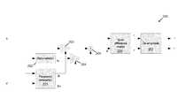
- a decorrelation module configured to receive the sum signal and provide a decorrelated sum signal;
- a parameter estimation module configured to calculate a first gain from a cross-correlation of the sum and difference signals and the power of the difference signal and a second gain from a cross-correlation of the sum and difference signals and the power of the sum and difference signals;
- a first amplifier configured to receive the sum signal and amplify the sum signal according to the first gain;
- a second amplifier configured to receive the decorrelated sum signal and amplify the decorrelated sum signal according to the second gain;
- a summing module configured to sum output signals from the first and second amplifiers; and
- an output stage configured to calculate an output stereo signal from a combination of the sum signal and an output signal from the summing module.
d′=g s ·s+g sd ·s d
where
represents the complex-valued inner product of the signal vectors x,y. The parameter ε is a small positive value to prevent division by zero. Therefore, effectively the parameter gs is calculated as the ratio of the complex-valued (complex-conjugate) cross correlation between the sum/difference signal pair and the power of the sum signal. This provides the least-squares fit. The parameter gsd is calculated as square root of the ratio of the residual signal power and the power of the sum signal.
g s =g s,measured·ƒ1(SNNR)
g sd =g sd,measured·ƒ2(SNNR)′
- [1] WO 2008/087577 A1
- [2] J. Breebaart, S. van de Par, A. Kohlrausch and E. Schuijers, “Parametric Coding of Stereo Audio”, in EURASIP J. Appl. Signal Process., vol 9, pp. 1305-1322 (2004).
- [3] J. Herre, K. Brandenburg, D. Lederer, “Intensity Stereo. Coding,” 96th AES Convention, Amsterdam, 1994, Preprint. 3799.
- [4] US 2006/0280310 A1.
- [5] Jot, J. M. & Chaigne, A. (1991), Digital Delay Networks for designing Artificial Reverb, 90th Convention of the Audio Engineering Society (AES), Preprint Nr. 3030, Paris, France.
- [6] Moorer, The Use of the Phase Vocoder in Computer Music Applications Journal of the Audio Engineering Society, Volume 26, Number 1/2, January/February 1978, pp 42-45.
- [7] P. Ekstrand, Bandwidth Extension of Audio Signals by Spectral Band Replication, Proc. 1st IEEE Benelux Workshop on Model based Processing and Coding of Audio (MPGA-2002), Leuven, Belgium, Nov. 15, 2002.
- [8] A. Härmä, M. Karjalainen, L. Savioja, V. Välimäki, U. K. Laine, and J. Huopaniemi. Frequency-warped signal processing for audio applications. J. Audio Eng. Soc., 48:1011-1031, 2000.
- [9] M. Schwartz, “Information Transmission, modulation, and noise”, 3ed, chapter 5-12
Claims (12)
Applications Claiming Priority (3)
| Application Number | Priority Date | Filing Date | Title |
|---|---|---|---|
| EP10250574 | 2010-03-25 | ||
| EP10250574.0 | 2010-03-25 | ||
| EP10250574.0A EP2369861B1 (en) | 2010-03-25 | 2010-03-25 | Multi-channel audio signal processing |
Publications (2)
| Publication Number | Publication Date |
|---|---|
| US20110235809A1 US20110235809A1 (en) | 2011-09-29 |
| US8638948B2 true US8638948B2 (en) | 2014-01-28 |
Family
ID=43332678
Family Applications (1)
| Application Number | Title | Priority Date | Filing Date |
|---|---|---|---|
| US13/070,613 Expired - Fee Related US8638948B2 (en) | 2010-03-25 | 2011-03-24 | Multi-channel audio signal processing |
Country Status (3)
| Country | Link |
|---|---|
| US (1) | US8638948B2 (en) |
| EP (1) | EP2369861B1 (en) |
| CN (1) | CN102201823B (en) |
Cited By (1)
| Publication number | Priority date | Publication date | Assignee | Title |
|---|---|---|---|---|
| US20140376755A1 (en) * | 2013-06-25 | 2014-12-25 | Samsung Electronics Co., Ltd. | Method for providing hearing aid compatibility mode and electronic device thereof |
Families Citing this family (7)
| Publication number | Priority date | Publication date | Assignee | Title |
|---|---|---|---|---|
| KR100889478B1 (en) * | 2007-11-23 | 2009-03-19 | 정원섭 | Apparatus for sound having multiple stereo imaging |
| UA107771C2 (en) | 2011-09-29 | 2015-02-10 | Dolby Int Ab | Prediction-based fm stereo radio noise reduction |
| EP2615739B1 (en) * | 2012-01-16 | 2015-06-17 | Nxp B.V. | Processor for an FM signal receiver and processing method |
| EP2830063A1 (en) | 2013-07-22 | 2015-01-28 | Fraunhofer-Gesellschaft zur Förderung der angewandten Forschung e.V. | Apparatus, method and computer program for decoding an encoded audio signal |
| WO2020030795A1 (en) * | 2018-08-10 | 2020-02-13 | Telefonaktiebolaget Lm Ericsson (Publ) | Multi-source quasi collocation of reference signals |
| CN110246508B (en) * | 2019-06-14 | 2021-08-31 | 腾讯音乐娱乐科技(深圳)有限公司 | Signal modulation method, device and storage medium |
| US20230041906A1 (en) * | 2021-08-03 | 2023-02-09 | Data Culpa, Inc. | Data lineage in a data pipeline |
Citations (20)
| Publication number | Priority date | Publication date | Assignee | Title |
|---|---|---|---|---|
| US3811011A (en) * | 1969-07-08 | 1974-05-14 | Itek Corp | Multiple image registration system |
| CN1197958A (en) | 1997-03-31 | 1998-11-04 | 索尼公司 | Encoding method and apparatus, decoding method and apparatus and recording medium |
| EP1206043A1 (en) | 2000-11-08 | 2002-05-15 | Sony International (Europe) GmbH | Noise reduction in a stereo receiver |
| US20030055636A1 (en) * | 2001-09-17 | 2003-03-20 | Matsushita Electric Industrial Co., Ltd. | System and method for enhancing speech components of an audio signal |
| US6563773B1 (en) * | 1999-09-22 | 2003-05-13 | Pioneer Corporation | Tracking control apparatus |
| WO2003090206A1 (en) | 2002-04-22 | 2003-10-30 | Koninklijke Philips Electronics N.V. | Signal synthesizing |
| US20050207585A1 (en) * | 2004-03-17 | 2005-09-22 | Markus Christoph | Active noise tuning system |
| JP2006148647A (en) * | 2004-11-22 | 2006-06-08 | Renesas Technology Corp | Power control circuit, semiconductor device using it, and transmitter/receiver circuit |
| US7085331B2 (en) * | 2001-06-09 | 2006-08-01 | Curitel Communications, Inc. | Apparatus and method for processing data using COPSK of wireless communication system |
| US20060190247A1 (en) * | 2005-02-22 | 2006-08-24 | Fraunhofer-Gesellschaft Zur Forderung Der Angewandten Forschung E.V. | Near-transparent or transparent multi-channel encoder/decoder scheme |
| US20060206316A1 (en) * | 2005-03-10 | 2006-09-14 | Samsung Electronics Co. Ltd. | Audio coding and decoding apparatuses and methods, and recording mediums storing the methods |
| US20060233380A1 (en) * | 2005-04-15 | 2006-10-19 | FRAUNHOFER- GESELLSCHAFT ZUR FORDERUNG DER ANGEWANDTEN FORSCHUNG e.V. | Multi-channel hierarchical audio coding with compact side information |
| US20070194952A1 (en) * | 2004-04-05 | 2007-08-23 | Koninklijke Philips Electronics, N.V. | Multi-channel encoder |
| US20070236858A1 (en) * | 2006-03-28 | 2007-10-11 | Sascha Disch | Enhanced Method for Signal Shaping in Multi-Channel Audio Reconstruction |
| US20080048628A1 (en) * | 2006-08-22 | 2008-02-28 | Lee Yong-Hee | Voltage converter and a method of using the same |
| WO2008087577A1 (en) | 2007-01-17 | 2008-07-24 | Nxp B.V. | Receiver for a multi-channel audio signal, method for processing a multi-channel audio signal and signal processing device |
| US20100014679A1 (en) * | 2008-07-11 | 2010-01-21 | Samsung Electronics Co., Ltd. | Multi-channel encoding and decoding method and apparatus |
| US20100023335A1 (en) * | 2007-02-06 | 2010-01-28 | Koninklijke Philips Electronics N.V. | Low complexity parametric stereo decoder |
| US20110106543A1 (en) * | 2008-06-26 | 2011-05-05 | France Telecom | Spatial synthesis of multichannel audio signals |
| US20130231940A1 (en) * | 2006-11-10 | 2013-09-05 | Panasonic Corporation | Parameter decoding apparatus and parameter decoding method |
-
2010
- 2010-03-25 EP EP10250574.0A patent/EP2369861B1/en not_active Not-in-force
-
2011
- 2011-03-23 CN CN201110076978.2A patent/CN102201823B/en not_active Expired - Fee Related
- 2011-03-24 US US13/070,613 patent/US8638948B2/en not_active Expired - Fee Related
Patent Citations (23)
| Publication number | Priority date | Publication date | Assignee | Title |
|---|---|---|---|---|
| US3811011A (en) * | 1969-07-08 | 1974-05-14 | Itek Corp | Multiple image registration system |
| CN1197958A (en) | 1997-03-31 | 1998-11-04 | 索尼公司 | Encoding method and apparatus, decoding method and apparatus and recording medium |
| US6169973B1 (en) | 1997-03-31 | 2001-01-02 | Sony Corporation | Encoding method and apparatus, decoding method and apparatus and recording medium |
| US6563773B1 (en) * | 1999-09-22 | 2003-05-13 | Pioneer Corporation | Tracking control apparatus |
| EP1206043A1 (en) | 2000-11-08 | 2002-05-15 | Sony International (Europe) GmbH | Noise reduction in a stereo receiver |
| US7715567B2 (en) | 2000-11-08 | 2010-05-11 | Sony Deutschland Gmbh | Noise reduction in a stereo receiver |
| US7085331B2 (en) * | 2001-06-09 | 2006-08-01 | Curitel Communications, Inc. | Apparatus and method for processing data using COPSK of wireless communication system |
| US20030055636A1 (en) * | 2001-09-17 | 2003-03-20 | Matsushita Electric Industrial Co., Ltd. | System and method for enhancing speech components of an audio signal |
| US20050254446A1 (en) * | 2002-04-22 | 2005-11-17 | Breebaart Dirk J | Signal synthesizing |
| WO2003090206A1 (en) | 2002-04-22 | 2003-10-30 | Koninklijke Philips Electronics N.V. | Signal synthesizing |
| US20050207585A1 (en) * | 2004-03-17 | 2005-09-22 | Markus Christoph | Active noise tuning system |
| US20070194952A1 (en) * | 2004-04-05 | 2007-08-23 | Koninklijke Philips Electronics, N.V. | Multi-channel encoder |
| JP2006148647A (en) * | 2004-11-22 | 2006-06-08 | Renesas Technology Corp | Power control circuit, semiconductor device using it, and transmitter/receiver circuit |
| US20060190247A1 (en) * | 2005-02-22 | 2006-08-24 | Fraunhofer-Gesellschaft Zur Forderung Der Angewandten Forschung E.V. | Near-transparent or transparent multi-channel encoder/decoder scheme |
| US20060206316A1 (en) * | 2005-03-10 | 2006-09-14 | Samsung Electronics Co. Ltd. | Audio coding and decoding apparatuses and methods, and recording mediums storing the methods |
| US20060233380A1 (en) * | 2005-04-15 | 2006-10-19 | FRAUNHOFER- GESELLSCHAFT ZUR FORDERUNG DER ANGEWANDTEN FORSCHUNG e.V. | Multi-channel hierarchical audio coding with compact side information |
| US20070236858A1 (en) * | 2006-03-28 | 2007-10-11 | Sascha Disch | Enhanced Method for Signal Shaping in Multi-Channel Audio Reconstruction |
| US20080048628A1 (en) * | 2006-08-22 | 2008-02-28 | Lee Yong-Hee | Voltage converter and a method of using the same |
| US20130231940A1 (en) * | 2006-11-10 | 2013-09-05 | Panasonic Corporation | Parameter decoding apparatus and parameter decoding method |
| WO2008087577A1 (en) | 2007-01-17 | 2008-07-24 | Nxp B.V. | Receiver for a multi-channel audio signal, method for processing a multi-channel audio signal and signal processing device |
| US20100023335A1 (en) * | 2007-02-06 | 2010-01-28 | Koninklijke Philips Electronics N.V. | Low complexity parametric stereo decoder |
| US20110106543A1 (en) * | 2008-06-26 | 2011-05-05 | France Telecom | Spatial synthesis of multichannel audio signals |
| US20100014679A1 (en) * | 2008-07-11 | 2010-01-21 | Samsung Electronics Co., Ltd. | Multi-channel encoding and decoding method and apparatus |
Non-Patent Citations (8)
| Title |
|---|
| Breebaart, J. et al., "Parametic Coding of Stereo Audio," J. Applied Signal Processing, vol. 9, pp. 1305-1322 (2004). |
| Breebaart, J. et al., "Parametric Coding of Stereo Audio," J. Applied Signal Processing, vol. 9, pp. 1305-1322 (2004). * |
| Ekstrand, P. "Bandwidth Extension of Audio Signals by Spectral Band Replication," Proc. 1st IEEE Benelux Workshop on Model Based Processing and Coding of Audio, pp. 53-58 (Nov. 15, 2002). |
| Extended European Search Report for Patent Appln. No. 10250574.0 (Jan. 18, 2011). |
| Harma, A., et al. "Frequency-Warped Signal Processing for Audio Applications," J. Audio Engineering Society, vol. 48, No. 11, pp. 1011-1031 (Nov. 2000). |
| Herre J. et al., "Intensity Stereo Coding," 96th Convention Audio Engineering Society, Preprint No. 3799 (P3.9), 11 pgs. (Feb. 1994). |
| Jot, J-M., "Digital Delay Networks for Designing Artificial Reverberators,", 90th Convention Audio Engineering Society, Preprint No. 3030 (E-2), 17 pgs. (Feb. 1991). |
| Moorer, J. "The Use of the Phase Vocoder in Computer Music Applications," J. Audio Engineering Society, vol. 26, No. 1/2, pp. 42-45 (Jan. 1978). |
Cited By (2)
| Publication number | Priority date | Publication date | Assignee | Title |
|---|---|---|---|---|
| US20140376755A1 (en) * | 2013-06-25 | 2014-12-25 | Samsung Electronics Co., Ltd. | Method for providing hearing aid compatibility mode and electronic device thereof |
| US9241224B2 (en) * | 2013-06-25 | 2016-01-19 | Samsung Electronics Co., Ltd. | Method for providing hearing aid compatibility mode and electronic device thereof |
Also Published As
| Publication number | Publication date |
|---|---|
| CN102201823A (en) | 2011-09-28 |
| EP2369861B1 (en) | 2016-07-27 |
| US20110235809A1 (en) | 2011-09-29 |
| EP2369861A1 (en) | 2011-09-28 |
| CN102201823B (en) | 2013-11-06 |
Similar Documents
| Publication | Publication Date | Title |
|---|---|---|
| US8638948B2 (en) | Multi-channel audio signal processing | |
| US8090122B2 (en) | Audio mixing using magnitude equalization | |
| US7283634B2 (en) | Method of mixing audio channels using correlated outputs | |
| EP2612322B1 (en) | Method and device for decoding a multichannel audio signal | |
| US7039204B2 (en) | Equalization for audio mixing | |
| CN101675471B (en) | Method and apparatus for processing audio signal | |
| US7715567B2 (en) | Noise reduction in a stereo receiver | |
| CN103069721B (en) | Reduce the pseudo-irrelevance in FM radio broadcast noise | |
| US20070223740A1 (en) | Audio spatial environment engine using a single fine structure | |
| KR101575185B1 (en) | Method for generating a downward sound format | |
| Romoli et al. | A combined approach for channel decorrelation in stereo acoustic echo cancellation exploiting time-varying frequency shifting | |
| EP2552027B1 (en) | Stereo decoding | |
| CN105229928A (en) | The method estimated for signal quality and control and circuit | |
| US10985851B2 (en) | Method and device for optimizing the radiofrequency power of an FM radiobroadcasting transmitter | |
| WO2008087577A1 (en) | Receiver for a multi-channel audio signal, method for processing a multi-channel audio signal and signal processing device | |
| US10003422B2 (en) | Method for processing an FM stereo signal | |
| US7313240B2 (en) | Noise reduction in a stereo receiver comprising an expander | |
| US9172479B2 (en) | Processor for an FM signal receiver and processing method | |
| US7826812B1 (en) | Digital carrier-recovery scheme for FM stereo detection | |
| JPH0419862Y2 (en) | ||
| US7362872B2 (en) | Method for noise reduction of a FM signal | |
| JPH06224788A (en) | Voice signal processor by band division |
Legal Events
| Date | Code | Title | Description |
|---|---|---|---|
| AS | Assignment |
Owner name: NXP, B.V., NETHERLANDS Free format text: ASSIGNMENT OF ASSIGNORS INTEREST;ASSIGNORS:SCHUIJERS, ERIK GOSUINUS PETRUS;DE BONT, SEBASTIAAN;SIGNING DATES FROM 20110202 TO 20110210;REEL/FRAME:026018/0165 |
|
| STCF | Information on status: patent grant |
Free format text: PATENTED CASE |
|
| AS | Assignment |
Owner name: MORGAN STANLEY SENIOR FUNDING, INC., MARYLAND Free format text: SECURITY AGREEMENT SUPPLEMENT;ASSIGNOR:NXP B.V.;REEL/FRAME:038017/0058 Effective date: 20160218 |
|
| AS | Assignment |
Owner name: MORGAN STANLEY SENIOR FUNDING, INC., MARYLAND Free format text: CORRECTIVE ASSIGNMENT TO CORRECT THE REMOVE APPLICATION 12092129 PREVIOUSLY RECORDED ON REEL 038017 FRAME 0058. ASSIGNOR(S) HEREBY CONFIRMS THE SECURITY AGREEMENT SUPPLEMENT;ASSIGNOR:NXP B.V.;REEL/FRAME:039361/0212 Effective date: 20160218 |
|
| AS | Assignment |
Owner name: MORGAN STANLEY SENIOR FUNDING, INC., MARYLAND Free format text: CORRECTIVE ASSIGNMENT TO CORRECT THE REMOVE APPLICATION 12681366 PREVIOUSLY RECORDED ON REEL 038017 FRAME 0058. ASSIGNOR(S) HEREBY CONFIRMS THE SECURITY AGREEMENT SUPPLEMENT;ASSIGNOR:NXP B.V.;REEL/FRAME:042985/0001 Effective date: 20160218 Owner name: MORGAN STANLEY SENIOR FUNDING, INC., MARYLAND Free format text: CORRECTIVE ASSIGNMENT TO CORRECT THE REMOVE APPLICATION 12681366 PREVIOUSLY RECORDED ON REEL 039361 FRAME 0212. ASSIGNOR(S) HEREBY CONFIRMS THE SECURITY AGREEMENT SUPPLEMENT;ASSIGNOR:NXP B.V.;REEL/FRAME:042762/0145 Effective date: 20160218 |
|
| FPAY | Fee payment |
Year of fee payment: 4 |
|
| AS | Assignment |
Owner name: NXP B.V., NETHERLANDS Free format text: RELEASE BY SECURED PARTY;ASSIGNOR:MORGAN STANLEY SENIOR FUNDING, INC.;REEL/FRAME:050745/0001 Effective date: 20190903 |
|
| AS | Assignment |
Owner name: MORGAN STANLEY SENIOR FUNDING, INC., MARYLAND Free format text: CORRECTIVE ASSIGNMENT TO CORRECT THE REMOVE APPLICATION 12298143 PREVIOUSLY RECORDED ON REEL 042762 FRAME 0145. ASSIGNOR(S) HEREBY CONFIRMS THE SECURITY AGREEMENT SUPPLEMENT;ASSIGNOR:NXP B.V.;REEL/FRAME:051145/0184 Effective date: 20160218 Owner name: MORGAN STANLEY SENIOR FUNDING, INC., MARYLAND Free format text: CORRECTIVE ASSIGNMENT TO CORRECT THE REMOVE APPLICATION 12298143 PREVIOUSLY RECORDED ON REEL 039361 FRAME 0212. ASSIGNOR(S) HEREBY CONFIRMS THE SECURITY AGREEMENT SUPPLEMENT;ASSIGNOR:NXP B.V.;REEL/FRAME:051029/0387 Effective date: 20160218 Owner name: MORGAN STANLEY SENIOR FUNDING, INC., MARYLAND Free format text: CORRECTIVE ASSIGNMENT TO CORRECT THE REMOVE APPLICATION 12298143 PREVIOUSLY RECORDED ON REEL 042985 FRAME 0001. ASSIGNOR(S) HEREBY CONFIRMS THE SECURITY AGREEMENT SUPPLEMENT;ASSIGNOR:NXP B.V.;REEL/FRAME:051029/0001 Effective date: 20160218 Owner name: MORGAN STANLEY SENIOR FUNDING, INC., MARYLAND Free format text: CORRECTIVE ASSIGNMENT TO CORRECT THE REMOVE APPLICATION12298143 PREVIOUSLY RECORDED ON REEL 042762 FRAME 0145. ASSIGNOR(S) HEREBY CONFIRMS THE SECURITY AGREEMENT SUPPLEMENT;ASSIGNOR:NXP B.V.;REEL/FRAME:051145/0184 Effective date: 20160218 Owner name: MORGAN STANLEY SENIOR FUNDING, INC., MARYLAND Free format text: CORRECTIVE ASSIGNMENT TO CORRECT THE REMOVE APPLICATION12298143 PREVIOUSLY RECORDED ON REEL 042985 FRAME 0001. ASSIGNOR(S) HEREBY CONFIRMS THE SECURITY AGREEMENT SUPPLEMENT;ASSIGNOR:NXP B.V.;REEL/FRAME:051029/0001 Effective date: 20160218 Owner name: MORGAN STANLEY SENIOR FUNDING, INC., MARYLAND Free format text: CORRECTIVE ASSIGNMENT TO CORRECT THE REMOVE APPLICATION12298143 PREVIOUSLY RECORDED ON REEL 039361 FRAME 0212. ASSIGNOR(S) HEREBY CONFIRMS THE SECURITY AGREEMENT SUPPLEMENT;ASSIGNOR:NXP B.V.;REEL/FRAME:051029/0387 Effective date: 20160218 Owner name: MORGAN STANLEY SENIOR FUNDING, INC., MARYLAND Free format text: CORRECTIVE ASSIGNMENT TO CORRECT THE REMOVE APPLICATION 12298143 PREVIOUSLY RECORDED ON REEL 038017 FRAME 0058. ASSIGNOR(S) HEREBY CONFIRMS THE SECURITY AGREEMENT SUPPLEMENT;ASSIGNOR:NXP B.V.;REEL/FRAME:051030/0001 Effective date: 20160218 |
|
| FEPP | Fee payment procedure |
Free format text: MAINTENANCE FEE REMINDER MAILED (ORIGINAL EVENT CODE: REM.); ENTITY STATUS OF PATENT OWNER: LARGE ENTITY |
|
| LAPS | Lapse for failure to pay maintenance fees |
Free format text: PATENT EXPIRED FOR FAILURE TO PAY MAINTENANCE FEES (ORIGINAL EVENT CODE: EXP.); ENTITY STATUS OF PATENT OWNER: LARGE ENTITY |
|
| STCH | Information on status: patent discontinuation |
Free format text: PATENT EXPIRED DUE TO NONPAYMENT OF MAINTENANCE FEES UNDER 37 CFR 1.362 |
|
| FP | Lapsed due to failure to pay maintenance fee |
Effective date: 20220128 |