US8621766B2 - Shoes, devices for shoes, and methods of using shoes - Google Patents
Shoes, devices for shoes, and methods of using shoes Download PDFInfo
- Publication number
- US8621766B2 US8621766B2 US13/708,883 US201213708883A US8621766B2 US 8621766 B2 US8621766 B2 US 8621766B2 US 201213708883 A US201213708883 A US 201213708883A US 8621766 B2 US8621766 B2 US 8621766B2
- Authority
- US
- United States
- Prior art keywords
- plate
- shoe
- shows
- hinge portion
- springs
- Prior art date
- Legal status (The legal status is an assumption and is not a legal conclusion. Google has not performed a legal analysis and makes no representation as to the accuracy of the status listed.)
- Active
Links
Images


Classifications
-
- A—HUMAN NECESSITIES
- A43—FOOTWEAR
- A43B—CHARACTERISTIC FEATURES OF FOOTWEAR; PARTS OF FOOTWEAR
- A43B13/00—Soles; Sole-and-heel integral units
- A43B13/14—Soles; Sole-and-heel integral units characterised by the constructive form
- A43B13/18—Resilient soles
- A43B13/181—Resiliency achieved by the structure of the sole
-
- A—HUMAN NECESSITIES
- A43—FOOTWEAR
- A43B—CHARACTERISTIC FEATURES OF FOOTWEAR; PARTS OF FOOTWEAR
- A43B3/00—Footwear characterised by the shape or the use
- A43B3/0031—Footwear characterised by the shape or the use provided with a pocket, e.g. for keys or a card
-
- A—HUMAN NECESSITIES
- A43—FOOTWEAR
- A43B—CHARACTERISTIC FEATURES OF FOOTWEAR; PARTS OF FOOTWEAR
- A43B13/00—Soles; Sole-and-heel integral units
- A43B13/14—Soles; Sole-and-heel integral units characterised by the constructive form
- A43B13/18—Resilient soles
- A43B13/181—Resiliency achieved by the structure of the sole
- A43B13/182—Helicoidal springs
-
- A—HUMAN NECESSITIES
- A43—FOOTWEAR
- A43B—CHARACTERISTIC FEATURES OF FOOTWEAR; PARTS OF FOOTWEAR
- A43B13/00—Soles; Sole-and-heel integral units
- A43B13/14—Soles; Sole-and-heel integral units characterised by the constructive form
- A43B13/18—Resilient soles
- A43B13/181—Resiliency achieved by the structure of the sole
- A43B13/185—Elasticated plates sandwiched between two interlocking components, e.g. thrustors
-
- A—HUMAN NECESSITIES
- A43—FOOTWEAR
- A43B—CHARACTERISTIC FEATURES OF FOOTWEAR; PARTS OF FOOTWEAR
- A43B7/00—Footwear with health or hygienic arrangements
- A43B7/14—Footwear with health or hygienic arrangements with foot-supporting parts
- A43B7/1405—Footwear with health or hygienic arrangements with foot-supporting parts with pads or holes on one or more locations, or having an anatomical or curved form
- A43B7/1415—Footwear with health or hygienic arrangements with foot-supporting parts with pads or holes on one or more locations, or having an anatomical or curved form characterised by the location under the foot
- A43B7/144—Footwear with health or hygienic arrangements with foot-supporting parts with pads or holes on one or more locations, or having an anatomical or curved form characterised by the location under the foot situated under the heel, i.e. the calcaneus bone
-
- A—HUMAN NECESSITIES
- A43—FOOTWEAR
- A43B—CHARACTERISTIC FEATURES OF FOOTWEAR; PARTS OF FOOTWEAR
- A43B7/00—Footwear with health or hygienic arrangements
- A43B7/14—Footwear with health or hygienic arrangements with foot-supporting parts
- A43B7/1405—Footwear with health or hygienic arrangements with foot-supporting parts with pads or holes on one or more locations, or having an anatomical or curved form
- A43B7/1415—Footwear with health or hygienic arrangements with foot-supporting parts with pads or holes on one or more locations, or having an anatomical or curved form characterised by the location under the foot
- A43B7/1445—Footwear with health or hygienic arrangements with foot-supporting parts with pads or holes on one or more locations, or having an anatomical or curved form characterised by the location under the foot situated under the midfoot, i.e. the second, third or fourth metatarsal
-
- A—HUMAN NECESSITIES
- A43—FOOTWEAR
- A43B—CHARACTERISTIC FEATURES OF FOOTWEAR; PARTS OF FOOTWEAR
- A43B7/00—Footwear with health or hygienic arrangements
- A43B7/14—Footwear with health or hygienic arrangements with foot-supporting parts
- A43B7/1405—Footwear with health or hygienic arrangements with foot-supporting parts with pads or holes on one or more locations, or having an anatomical or curved form
- A43B7/1475—Footwear with health or hygienic arrangements with foot-supporting parts with pads or holes on one or more locations, or having an anatomical or curved form characterised by the type of support
- A43B7/148—Recesses or holes filled with supports or pads
-
- A—HUMAN NECESSITIES
- A43—FOOTWEAR
- A43B—CHARACTERISTIC FEATURES OF FOOTWEAR; PARTS OF FOOTWEAR
- A43B7/00—Footwear with health or hygienic arrangements
- A43B7/32—Footwear with health or hygienic arrangements with shock-absorbing means
Landscapes
- Health & Medical Sciences (AREA)
- Epidemiology (AREA)
- General Health & Medical Sciences (AREA)
- Public Health (AREA)
- Footwear And Its Accessory, Manufacturing Method And Apparatuses (AREA)
Abstract
A shoe includes a first plate and a second plate that are located in a forefoot portion of the shoe between an upper and an outsole of the shoe, and one or more springs for biasing the first plate and the second plate apart from each other. A device for a shoe includes a first plate and a second plate that are installable in a forefoot portion of the shoe, and an energy return member positioned between the first plate and the second plate. A method of using a shoe includes applying, with a foot, a force on at least one of two plates that is positioned in a forefoot portion of a shoe, so as to move the two plates together and increase a loading of a spring, and launching the foot due to the two plates being moved apart by the spring as the foot is being lifted.
Description
This application is a continuation of U.S. patent application Ser. No. 12/754,333, filed Apr. 5, 2010, incorporated herein by reference in its entirety, which claims priority from Provisional Application U.S. Application 61/299,761, filed Jan. 29, 2010, incorporated herein by reference in its entirety. U.S. application Ser. No. 12/754,333, filed Apr. 5, 2010 is a Continuation-In-Part of U.S. application Ser. No. 12/467,679, filed May 18, 2009, incorporated herein by reference in its entirety, which claims priority from Provisional Application U.S. Application No. 61/168,533, filed Apr. 10, 2009, incorporated herein by reference in its entirety.
1. Field of the Invention
Embodiments of the present invention relate in general to footwear, and particularly to energy absorption and return systems for use in footwear.
2. Related Art
In prior U.S. Pat. Nos. 5,437,110 and 5,596,819, a discussion was provided of the desirability of providing adjustable foot-strike energy shock absorption and return. Those patents disclosed the use of a device disposed in the midsole of a shoe under the heel. The device used an adjustable mechanism to store and return to the wearer's foot shock energy experienced during walking or running.
Those prior patents discussed a variety of related art, including U.S. Pat. Nos. 4,486,964, 4,506,460, 2,357,281, 2,394,281, 4,709,489, 4,815,221, 4,854,057, and 4,878,300 as disclosing a variety of spring systems for shoes that related to heel-strike energy absorption and return. Since the time of those patents, other patents and applications have addressed a variety of spring mechanisms for shoes. See, e.g., U.S. Pat. Nos. 6,282,814, 6,751,891, 6,865,824, 6,886,274, 7,159,338, 7,219,447, 7,287,340, and 7,290,354, as well as published applications 2005/0166422 and 2009/0064536.
A step forward or stride consists of a dynamic process sometimes referred to as gait. The science surrounding gait is extensive, but embodiments of the present invention focus upon that aspect that a layman might identify as toe-off when jumping. Gait can be broken down into three distinct phases as follows: (1) the contact phase which begins with heel strike and continues until the foot is flat on the surface, (2) the mid-stance phase beginning from the foot flat and a shift of body weight and continuing until the heel rises, and, lastly, (3) the propulsion phase where toe-off (or jumping) would occur.
The related art does not focus upon the propulsion phase of the gait cycle. Most of the devices are directed to the contact phase and use heel-related mechanisms to store and return energy. Because energy stored in the contact phase via a heel spring is dissipated by the time the propulsion phase begins, heel springs have not proven effective for energy storage and return. Some of the related art also use springs under the ball of the foot. In addition to not being effective in the propulsion phase, such devices can have adverse physiological effects on the foot if not properly positioned.
A shoe in accordance with various embodiments of the present invention comprises a first plate and a second plate that are located in a forefoot portion of the shoe between an upper and an outsole of the shoe, and one or more springs for biasing the first plate and the second plate apart from each other. In various embodiments, the shoe further comprises filler material disposed between the first plate and the second plate. Also, in various embodiments, the filler material has one or more openings in which the one or more springs are positioned.
In some embodiments, the one or more springs comprise at least one compression spring disposed between the first and second plates. Also, in some embodiments, the one or more springs comprise a torsion spring connected to the first and second plates. In various embodiments, the first plate and the second plate are parts of a single continuous member.
In various embodiments, the one or more springs comprise a plurality of springs that are arranged in at least two rows. Also, in various embodiments, the one or more springs comprise a plurality of springs that are arranged in at least three rows. In some embodiments, the one or more springs comprise at least two springs that are of different sizes and the smaller of the at least two springs is positioned closer to a front of the shoe than the larger of the at least two springs. Also, in some embodiments, the one or more springs comprise a plurality of springs that are located across substantially an entire area defined by the forefoot portion of the shoe.
In various embodiments, the one or more springs comprise a plurality of springs that are arranged to be in at least one of a rectangular, square, circular, oval, or triangular pattern. Also, in various embodiments, the first plate and the second plate are each in a substantially circular shape and at least one spring of the one or more springs is attached at a center of each of the first and second plates. In some embodiments, the one or more springs comprise a plurality of springs that are arranged such that at least one spring is located under each toe of a user.
A device in accordance with various embodiments of the present invention comprises a first plate and a second plate that are installable in a forefoot portion of a shoe, and an energy return member positioned between the first plate and the second plate. In various embodiments, the energy return member comprises a spring. Also, in various embodiments, the energy return member comprises a rubber half-ball shaped protrusion. In some embodiments, the energy return member comprises a pad with a cylindrical protrusion and a spring positioned around the cylindrical protrusion.
A shoe in accordance with various embodiments of the present invention comprises a midsole having a heel portion, a ball portion, and a forefoot portion, and a device comprising two plates and a spring, where the device is located in a cavity in the forefoot portion of the midsole. In various embodiments, the spring is located between the two plates. In some embodiments, the shoe further comprises an outsole having an opening to expose at least a portion of the device. Also, in some embodiments, at least one of the two plates is at least partially transparent. In various embodiments, the shoe further comprises a sockliner having a propulsion enhancement material on a bottom surface of a forefoot portion of the sockliner and a heel shock absorber on a bottom surface of a heel portion of the sockliner. Also, in various embodiments, the shoe further comprises a shank attached to the midsole.
A method in accordance with various embodiments of the present invention comprises applying, with a foot, a force on at least one of two plates that is positioned in a forefoot portion of a shoe, so as to move the two plates together and increase a loading of a spring, and then launching the foot due to the two plates being moved apart by the spring as the foot is being lifted.
A device in accordance with various embodiments of the present invention is located ahead of the ball of the foot and directly below the forefoot of the foot in a forefoot portion of a shoe. In various embodiments, the device stores and returns energy during the propulsion phase of a gait. In some embodiments, the device includes opposing plates hinged together and biased apart by a torsion spring that may be adjustable. Also, in some embodiments, lightweight foam is disposed between the plates. In other embodiments, additional springs, such as wave springs, or the like, may be disposed within or outside of foam at the front of the device.
Such devices are very effective in storing and returning energy where an athlete needs it most: at the front of the shoe, which is where the toe-off in running or jumping occurs. Furthermore, in various embodiments, the device replaces a portion of the midsole that would otherwise be under the forefoot, and is thus easy to install in a production environment, as it simply is affixed to the outsole. The use of a torsion spring in various embodiments allows for easy adjustability of the device by a wearer of the shoe.
A shoe in accordance with various embodiments of the present invention comprises an upper, an outsole, a pair of hinged plates attached between the outsole and the upper in a forefoot portion of the shoe, and a spring biasing the plates apart, whereby energy is stored and returned during a propulsion phase of a gait cycle in a human step.
In various embodiments, the shoe further comprises foam disposed between the plates. Also, in various embodiments, the shoe further comprises a shroud enclosing an outer periphery of the plates. In some embodiments, the spring comprises a torsion spring disposed in a hinge portion of the plates. Also, in some embodiments, the torsion spring is adjustable.
In various embodiments, the spring comprises at least one wave spring disposed between the plates. In some embodiments, the shoe further comprises an energy return material disposed between the plates. In some embodiments, the energy return material comprises rubber or Hytrel®. In various embodiments, one of the plates wraps around a portion of the upper to form a toe bumper.
A device in accordance with various embodiments of the present invention is installed in a forefoot portion of a shoe between an upper and an outsole of the shoe, and is used to store and return energy during a propulsion phase of a gait cycle in a human step. In various embodiments, the device comprises a pair of opposing plates, hinge means for attaching the plates together at one end, and spring means for biasing the plates apart, whereby, when a wearer of the shoe moves into an apex of a gait cycle, a force applied on the plates pushes the plates together, increasing a loading of the spring means, and providing the wearer with a launch factor equal to a release of torque from the spring means.
In some embodiments, the spring means comprises a torsion spring. Also, in some embodiments, the spring means further comprises at least one wave spring. In various embodiments, the device further comprises means for precluding debris from entering an area between the plates. In some embodiments, the means for precluding debris from entering the area between the plates comprises foam. Also, in some embodiments, the means for precluding debris from entering the area between the plates comprises a shroud along a peripheral portion of the plates. In various embodiments, the spring means comprises an adjustment means for changing a force applied by the spring means to the plates to bias them apart.
A shoe in accordance with various embodiments of the present invention comprises an outsole having a heel portion, a ball portion, and a forefoot portion, and a device comprising two plates and a spring, where the device is located at least partially above the forefoot portion of the outsole. In various embodiments, the shoe further comprises a midsole, and the device is located in a cavity in the midsole. In some embodiments, the spring is located between the two plates.
A method in accordance with various embodiments of the present invention allows for storing and returning energy during a propulsion phase of a gait cycle in a human step using a device in a shoe including two plates and a spring that biases the two plates apart from each other. In various embodiments, the method comprises applying, with a foot, a force on at least one of the two plates that is positioned in the shoe beneath a forefoot portion of the foot, so as to move the two plates together and increase a loading of the spring, and launching the foot due to the two plates being moved apart by the spring as the foot is being lifted.
Referring to FIG. 1 , a shoe 5 is provided with a device 10 according to an embodiment of the present invention. The device 10 is mounted in an outsole 22 of the shoe 5, as shown in more detail in FIG. 2 . With reference to FIGS. 1 , 2, and 5, the device 10 includes a top plate 12 and a bottom plate 14 that are hinged together via a pin 18 (or similar means). In various embodiments, the plates 12 and 14 are designed such that they have a very limited motion around a hinge axis. Also, in various embodiments, in a neutral position the plates 12 and 14 are parallel to each other, forming what might be explained as a duck-bill, as shown in FIGS. 3 and 4 . In some embodiments, the plates 12 and 14 have a limited motion that allows movement toward one another but not opening beyond (any more than) the two plates being parallel to each other.
With reference to FIG. 1 , various materials could be used for the plates 12 and 14, including polymer, block polymer, monomer, etc., that exhibit properties conducive to use in processes known as injection molding, and in some cases extrusion and the like, or other types of molding such as compression molding, etc. In various embodiments, material is selected for rigidity, because in practice the device 10 will be subjected to tremendous force as a wearer goes through a gait cycle ending up on the balls of the feet. At the apex of a propulsion phase of the gait cycle, the device 10 will be subjected to several times the wearer's body weight as the device 10 is “loading”. During this loading, it may be desirable that the device 10 does not deform under stress. Such deformity may result in loss of load factor resulting in diminished return of energy and a corresponding decrease in the actual intended performance. As such, thin steel is potentially usable to reinforce other materials to ensure the requisite rigidity.
A variety of hinge mechanisms could be used with the plates 12 and 14, such as a barrel hinge, butt hinge, living hinge, plain hinge, or others. In various embodiments, a barrel hinge can include molded features to control a movement of the plates 12 and 14 around its axis, to prevent it from springing open, such as a slot and key feature, or notched stop. A barrel hinge would form the two plates 12 and 14 into a single device with a single axis of rotation.
With reference to FIGS. 1 , 2, and 5, in various embodiments a helical torsion spring 16 may encircle the hinge pin 18, and may bias the plates 12 and 14 apart consistent with a strength of the particular spring utilized. In various embodiments, the helical torsion spring 16 is constructed from a metal wire or rod twisted or formed into a helical coil. In such embodiments, each end of the coil may be biased against the plates 12 and 14. Such torsion springs may be similar to those shown in U.S. Pat. No. 5,464,197. That patent shows a coil spring member with arms that provide an opposing bias. Adjustment of the torsion may be achieved via an inner coil which acts to control the deformation of an outer coil. In various embodiments of the present invention, a torsion spring could be located within a barrel hinge formed as an integral member of the top and bottom plates 12 and 14. Once the device 10 has been properly assembled and installed within the forepart of footwear, and the wearer of the footwear moves into an apex of a gait cycle (i.e. toe-off in jumping), the force applied to the top plate 12 will push the two plates 12 and 14 together. This will increase the torque loading of the helical torsion spring 16, and provide the wearer with a launch factor equal to a release of torque from the helical torsion spring 16.
In various embodiments, between the plates 12 and 14 there can be lightweight foam 20, as shown in FIGS. 1-3 . This component's purpose is basically as filler, and may extend partially (FIG. 8 ) or completely (FIG. 2 ) between the plates 12 and 14. In various embodiments, the device 10 may perform optimally in a case where a space between the plates 12 and 14 is void or empty. However, given the normal spectrum of use for footwear, it might not be desirable to leave the space empty in many instances. Dirt, mud, water, snow, ice, etc. (debris) may find its way within the space and could significantly decrease or even destroy the function of the device. Therefore, various embodiments include a means of blocking debris from entering the space between the plates 12 and 14. Because the device 10 of various embodiments would perform optimally without any material between the plates 12 and 14, it may be desirable for performance reasons to include a material that is lightweight, reflects good tear strength values, and that possesses specific compression properties. In addition to the criteria above, the ideal candidate foam 20 in various embodiments would compress under very low loading and compress to 30% of original thickness gauge—or more. Based upon these criteria, the foam 20 would preferably be of an open cell type. Thus, polyurethane, rubber, rubber latex, PVC or polyethylene can be used in various embodiments.
One purpose of the foam 20 is to avoid debris collecting between the plates 12 and 14. The foam 20 may slightly inhibit the performance of the device 10 in various embodiments, since it adds resistance in the loading phase of performance. As such, in an alternative embodiment of the invention shown in FIG. 7 , the foam 20 (FIG. 3 ) may be replaced with a front shroud 30 on one of the plates 12, 14 (in FIG. 7 , it is shown attached to the top plate 12). In various embodiments, the shroud 30 acts to keep debris from entering between the plates 12 and 14, and wraps around a perimeter of the toe area.
In addition, with reference to FIGS. 9 a, 9 a, 10, and 11, in various embodiments the foam 20 may be reduced in size or removed completely to allow the use of one or more other springs 32, 34, 36. The springs 32, 34, 36 assist the torsion spring 16 in providing propulsion to the wearer of the shoe. In various embodiments, such additional springs could be wave springs as shown in U.S. Pat. No. 4,901,987, or the like. Wave springs are particularly advantageous because the energy return is almost entirely axial, which would serve to press the plates 12 and 14 apart after compression. The springs 32, 34, 36 could be attached directly to the top and bottom plates 12 and 14 in various embodiments. With reference to FIG. 12 , in various embodiments an energy return or rebound material 48 may be disposed between the plates 12 and 14. In some embodiments, the energy return material 48 comprises rubber, Hytrel®, or the like, and creates an additional energy return effect.
With reference to FIG. 9 a, in various embodiments the top plate 12 and the bottom plate 14 are manufactured as separate units and may have portions in contact with each other at a contact location 85. With reference to FIG. 9 b, in various other embodiments, the top plate 12 and the bottom plate 14 are manufactured as a single continuous unit.
As mentioned and as illustrated in FIG. 2 , in various embodiments the device 10 is mounted to the outsole 22 under a forefoot region by conventional means (gluing, stitching, etc.) and replaces the midsole 38 in the forefoot portion of the shoe 5. Thus, in such embodiments, the midsole 38 would extend only from the heel portion of the outsole 22 up to the device 10. With reference to FIG. 2 , the shoe 5 may be described with respect to different portions of the shoe 5 along a length of the shoe 5, including a heel portion 52, an arch portion 54, a ball portion 56, and a forefoot portion 58.
With reference to FIG. 1 , in various embodiments, an optimal function of the device 10 within the shoe 5 requires an absence of any material (foam/rubber/etc.) between the device and the shoe upper 24. In other words, it is desirable in various embodiments to have the shoe upper 24 sit directly on the device 10 in the forepart, as shown in FIG. 1 . Therefore, with reference to FIGS. 1 and 6 , in various embodiments the top plate 12 of the device 10 would be configured to wrap up around the shoe upper 24 and in addition to its primary function of propulsion, forms features such as a toe bumper 26 and a sidewall 28. Such a unique construction with the top plate 12 configured to wrap up around the shoe upper 24 may create a very rigid toe bumper 26 and sidewall 28.
With this approach, an alternative embodiment for the top plate 12 would have the top plate 12 manufactured from more typical, softer/flexible materials (rubber/foam/etc.) and a secondary component then added to it (e.g. steel) added to provide rigidity directly above the bottom plate 14. The bottom plate 14 in such embodiments may still be manufactured from the rigid materials.
The heel shock absorber 820 a is located at a heel portion of the sockliner 310 a and may be made of Poron®, thermoplastic material, or the like. Poron® is a shock absorption substance that comprises microcellular polyurethane and is available from Rogers Corp. The heel shock absorber 820 a may be provided as a sheet under the heel of the sockliner 310 a. The propulsion enhancement material 810 a may be provided as a sheet under the forefoot of the sockliner 310 a.
In various other embodiments, a sheet of Poron® or other cushioning material may be attached under the forefoot portion of the sockliner 310 b rather than using the propulsion enhancement material 810 b. Such embodiments with cushioning material under the forefoot portion of the sockliner 310 b would provide more cushioning for a user. Also, in some embodiments, a sheet of Poron® or other cushioning material may cover a substantial portion of the entire bottom surface of the sockliner 310 b or even the entire bottom surface of the sockliner 310 b for added cushioning for a user. In some embodiments, a sockliner may be provided without the propulsion enhancement material 810 b or the heel shock absorber 820 b.
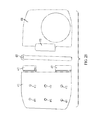
In particular, FIG. 30 shows portions of the top plate 410 that are exposed through the openings 530 of the filler material 520. Also shown in FIG. 30 are two rows of three springs 500 that may be placed in the openings 530 of the filler material 520. A diameter of the openings 530 may be slightly larger than a diameter of the springs 500 to allow the springs 500 to be placed in the corresponding openings 530. The air openings 470 in the top plate 410 are aligned to be located within an area of the openings 530 and open areas of the springs 500.
The springs 7003 shown in FIG. 76 are coil springs. In various embodiments, the spring 7003 may be a wave springs, or the like. In yet other embodiments, a combination of wave and coil springs may be used in the device 400 s. Each pad 7005 may include a cylindrical protrusion 7007 around which a corresponding spring 7003 is positioned, and the cylindrical protrusion 7007 may prevent the spring 7003 from being compressed beyond exhaustion. Such cylindrical protrusions 7007 with springs 7003 may act as energy return members. In various other embodiments, a protrusion of a different shape than cylindrical may be used.
Various embodiments provide a method of manufacturing a shoe. The method includes providing a midsole with a cavity in a forefoot portion of the midsole, assembling a device with a filler material and springs located between top and bottom plates, with the springs located in openings in the filler material. The method may include putting a pin through hinges of the top and bottom plates. The method may further include placing the device in the cavity in the midsole, placing an insole over the device and the midsole, and placing a sockliner over the insole. In various embodiments, the method includes attaching a propulsion enhancement material to a bottom side of a forefoot portion of the sockliner, and attaching a heel shock absorber to a bottom side of a heel portion of the sockliner. In some embodiments, the method includes attaching a shank to the midsole. In some embodiments, the method includes providing a window in an outsole and attaching the midsole to the outsole in a location such that the device is at least partially visible through the window in the outsole.
Embodiments of the present invention include shoes that may increase the vertical leap of an individual. Embodiments of the present invention may include a device placed in a cavity in a shoe. The device may be located under the forefoot in front of a ball of the foot and a flex zone of the shoe.
An embodiment of the device may include two plates made of a strong light weight rigid material. In an example embodiment, the rigid material may be high-durometer Pebax®, or thermoplastic materials such as TPU® or TPX®. Pebax® is a high performance elastomer which offers outstanding compression properties while providing excellent durability which increases fatigue resistance. The two plates of the device may be joined at a hinge. In an example embodiment, the hinge may be seamless to provide strength and support.
An embodiment of the device may include a nest that includes a filler material such as high-rebound EVA. The filler material may be located between the top and the bottom Pebax® plates. One embodiment of the filler material may include up to 8 circular die-cut holes. The holes may be configured to house vertical compression springs with a high bias force pushing the plates apart with a high amount of torque and energy return.
A high density shank may be located behind the device on the outsole of the shoe. The shank provides another level of engagement in a compression-propulsion-liftoff response method. The shank may be made of high durometer Pebax® and provides a level of stability between the forefoot and the heel portions of the shoe. The shank also absorbs shock and enhances the transfer of energy to the device to increase a vertical leap of an individual.
The combination of the three separate energy return substances: Pebax®, rebound EVA, and compression springs of the device working in concert increases the vertical leap of an individual. Since in various embodiments the device is inserted in the midsole of a shoe, the individual wearing the shoe according to embodiments of the present invention does not feel the device against their foot.
In an example embodiment, utilizing extremely high rebound EVA in the midsole of the shoe as well as in the insole that lies underneath the sockliner of the shoe provides cushioning, comfort, and the return of energy to the foot during a jumping or liftoff phase. The sockliner may include highly advanced materials designed to provide shock absorption under the heel and additional energy return under the forefoot to further propel the user upward during the liftoff phase of the jump. In one example embodiment, the material under the heel may be made of Poron®, a shock absorption substance, and under the forefoot portion of the sockliner may lie a sheet of ESS, which is a propulsion enhancement material. In various other embodiments, a shock absorption material, such as Poron® or other cushioning material, may be attached under both the heel and forefoot portion of the sockliner, or even cover an entire bottom surface of the sockliner, to provide added cushioning.
According to various embodiments of the present invention, when an athlete applies force to the front of the foot in preparation for liftoff, the shank, sockliner, insole, midsole, device, and the outsole all compress to generate a huge amount of energy exerted downward into the device. As the athlete begins to release the massive force that has been exerted downward, the energy is transferred in reverse order up through the device to provide a dramatic lift that increases the vertical leap of the athlete wearing the shoe. In various embodiments, providing the sockliner with the propulsion enhancement material, such as ESS attached to a forefoot portion of the bottom of the sockliner, would provide for an enhanced return of energy and added lift during a jump. In various embodiments where the sockliner is provided with cushioning material under the forefoot portion of the sockliner rather than the propulsion enhancement material, lift would still be provided by the shank, insole, midsole, device, and outsole working together.
Embodiments of a top and bottom plate for a device may be shaped to be oval, round, elliptical, rectangular, or even irregular shapes. Embodiments may include smaller compression springs assembled around an interior perimeter inside an EVA nest and a larger compression spring in a die-cut hole located at a center of the EVA nest. Embodiments of the top and bottom plates with Pebax may have two levels of hardness of about 40° or 63°. In yet other embodiments, the hardness of high elasticity EVA inserted around springs may be 35°.
Various embodiments of the present invention include springs with a wire having a thickness of about 1.2 mm and an inner diameter of the spring coil of about 15 mm. In various embodiments of the present invention, the height of each spring may be about 5 mm or about 7 mm. One advantage of using high elasticity EVA can be that it keeps springs firmly in place and prevents sideways movement of the springs during compression. Embodiments of the filler material may have hardness of about 35°, which may be less than the hardness of the springs. Any desirable hardness of the filler material may be used.
In an embodiment of the present invention, a thickness for a midsole at the forefront may be from about 8 to 12 mm. In yet another embodiment of the present invention, the plates may be made of rigid materials like Delrin (Acetal or POM) and the plates may be about 3 mm thick. In yet another embodiment of the present invention, a device in a shoe may be visible to a user of the shoe through a lateral or a medial side wall of the shoe. In yet another embodiment of a device, top and bottom plates for the device may remain parallel throughout the compression and the expansion of the device. Various embodiments of the present invention may be described as creating a spring sandwich of the two plates holding the filler materials and the springs, and can be used as a cassette to be dropped into a cavity in a midsole of a shoe.
The embodiments disclosed herein are to be considered in all respects as illustrative, and not restrictive of the invention. The present invention is in no way limited to the embodiments described above. Various modifications and changes may be made to the embodiments without departing from the spirit and scope of the invention. Various modifications and changes that come within the meaning and range of equivalency of the claims are intended to be within the scope of the invention.
Claims (16)
1. A shoe, comprising:
a first plate and a second plate that are separate units and that are entirely located in a forefoot portion of the shoe between an upper and an outsole of the shoe, the first plate having a first hinge portion and a second hinge portion, and the second plate having a hinge portion;
one or more springs for biasing the first plate and the second plate apart from each other;
a pin that passes through the first hinge portion of the first plate and the hinge portion of the second plate to hold together the first plate and the second plate;
wherein the first plate is at least partially rotatable about the pin;
wherein the hinge portion of the second plate is located between the first hinge portion of the first plate and the second hinge portion of the first plate;
wherein the hinge portion of the second plate is in contact with the first hinge portion of the first plate and the second hinge portion of the first plate; and
wherein an outer edge of the first hinge portion of the first plate is recessed from an outer edge of a top portion of the first plate in order to accommodate the pin such that an end of the pin is flush with the outer edge of the top portion of the first plate.
2. A shoe, comprising:
a first plate and a second plate that are entirely located in a forefoot portion of the shoe between an upper and an outsole of the shoe, the first plate having a first hinge portion and a second hinge portion, and the second plate having a hinge portion that is located between the first hinge portion of the first plate and the second hinge portion of the first plate;
a pin that passes through the first hinge portion of the first plate and the hinge portion of the second plate and the second hinge portion of the first plate to hold together the first plate and the second plate; and
an outer edge of the first hinge portion of the first plate is recessed from an outer edge of a top portion of the first plate in order to accommodate the pin such that an end of the pin is flush with the outer edge of the top portion of the first plate.
3. The shoe of claim 2 , wherein the first hinge portion of the first plate curls downward from a top portion of the first plate; and wherein the hinge portion of the second plate curls upward from a bottom portion of the second plate.
4. The shoe of claim 2 , further comprising one or more springs for biasing the first plate and the second plate apart from each other.
5. The shoe of claim 2 , wherein the hinge portion of the second plate is in contact with the first hinge portion of the first plate and the second hinge portion of the first plate.
6. The shoe of claim 2 , wherein the first plate is at least partially rotatable about the pin.
7. The shoe of claim 2 , wherein the first hinge portion of the first plate curls under the pin.
8. The shoe of claim 2 , wherein the hinge portion of the second plate curls over the pin.
9. The shoe of claim 2 , wherein the first plate is configured to move independently around the pin.
10. The shoe of claim 2 , wherein the first and the second hinges of the first plate are configured to move independently from the hinge of the second plate.
11. A method, comprising:
providing a first plate and a second plate that are entirely located in a forefoot portion of the shoe between an upper and an outsole of the shoe, the first plate having a first hinge portion and a second hinge portion, and the second plate having a hinge portion;
placing the second hinge portion of the second plate between the first hinge portion of the first plate and the second hinge portion of the first plate; and
passing a pin through the first hinge portion of the first plate and the hinge portion of the second plate to hold together the first plate and the second plate;
wherein said providing includes forming an outer edge of the first hinge portion of the first plate to be recessed from an outer edge of a top portion of the first plate in order to accommodate the pin such that an end of the pin is flush with the outer edge of the top portion of the first plate.
12. The method of claim 11 , further comprising biasing the first plate and the second plate from each other using one or more springs.
13. The method of claim 11 , wherein the hinge portion of the second plate is in contact with the first hinge portion of the first plate and the second hinge portion of the first plate.
14. The method of claim 11 , further comprising rotating the first plate at least partially about the pin.
15. The method of claim 11 , further comprising moving the first plate around the pin independently of movement of the second plate.
16. The method of claim 11 , further comprising independently moving the first hinge of the first plate and the hinge of the second plate.
Priority Applications (3)
| Application Number | Priority Date | Filing Date | Title |
|---|---|---|---|
| US13/708,883 US8621766B2 (en) | 2009-04-10 | 2012-12-07 | Shoes, devices for shoes, and methods of using shoes |
| US14/095,941 US8732983B2 (en) | 2009-04-10 | 2013-12-03 | Shoes, devices for shoes, and methods of using shoes |
| US14/095,950 US9364044B2 (en) | 2009-04-10 | 2013-12-03 | Shoes, devices for shoes, and methods of using shoes |
Applications Claiming Priority (5)
| Application Number | Priority Date | Filing Date | Title |
|---|---|---|---|
| US16853309P | 2009-04-10 | 2009-04-10 | |
| US12/467,679 US8112905B2 (en) | 2009-04-10 | 2009-05-18 | Forefoot catapult for athletic shoes |
| US29976110P | 2010-01-29 | 2010-01-29 | |
| US12/754,333 US8347526B2 (en) | 2009-04-10 | 2010-04-05 | Shoes, devices for shoes, and methods of using shoes |
| US13/708,883 US8621766B2 (en) | 2009-04-10 | 2012-12-07 | Shoes, devices for shoes, and methods of using shoes |
Related Parent Applications (1)
| Application Number | Title | Priority Date | Filing Date |
|---|---|---|---|
| US12/754,333 Continuation US8347526B2 (en) | 2009-04-10 | 2010-04-05 | Shoes, devices for shoes, and methods of using shoes |
Related Child Applications (2)
| Application Number | Title | Priority Date | Filing Date |
|---|---|---|---|
| US14/095,950 Continuation US9364044B2 (en) | 2009-04-10 | 2013-12-03 | Shoes, devices for shoes, and methods of using shoes |
| US14/095,941 Continuation US8732983B2 (en) | 2009-04-10 | 2013-12-03 | Shoes, devices for shoes, and methods of using shoes |
Publications (2)
| Publication Number | Publication Date |
|---|---|
| US20130091735A1 US20130091735A1 (en) | 2013-04-18 |
| US8621766B2 true US8621766B2 (en) | 2014-01-07 |
Family
ID=42933185
Family Applications (4)
| Application Number | Title | Priority Date | Filing Date |
|---|---|---|---|
| US12/754,333 Active 2030-06-10 US8347526B2 (en) | 2009-04-10 | 2010-04-05 | Shoes, devices for shoes, and methods of using shoes |
| US13/708,883 Active US8621766B2 (en) | 2009-04-10 | 2012-12-07 | Shoes, devices for shoes, and methods of using shoes |
| US14/095,950 Active 2030-03-04 US9364044B2 (en) | 2009-04-10 | 2013-12-03 | Shoes, devices for shoes, and methods of using shoes |
| US14/095,941 Active US8732983B2 (en) | 2009-04-10 | 2013-12-03 | Shoes, devices for shoes, and methods of using shoes |
Family Applications Before (1)
| Application Number | Title | Priority Date | Filing Date |
|---|---|---|---|
| US12/754,333 Active 2030-06-10 US8347526B2 (en) | 2009-04-10 | 2010-04-05 | Shoes, devices for shoes, and methods of using shoes |
Family Applications After (2)
| Application Number | Title | Priority Date | Filing Date |
|---|---|---|---|
| US14/095,950 Active 2030-03-04 US9364044B2 (en) | 2009-04-10 | 2013-12-03 | Shoes, devices for shoes, and methods of using shoes |
| US14/095,941 Active US8732983B2 (en) | 2009-04-10 | 2013-12-03 | Shoes, devices for shoes, and methods of using shoes |
Country Status (2)
| Country | Link |
|---|---|
| US (4) | US8347526B2 (en) |
| TW (1) | TW201043162A (en) |
Cited By (6)
| Publication number | Priority date | Publication date | Assignee | Title |
|---|---|---|---|---|
| US20120023784A1 (en) * | 2009-04-10 | 2012-02-02 | Athletic Propulsion Labs LLC | Shoes, devices for shoes, and methods of using shoes |
| US8732983B2 (en) | 2009-04-10 | 2014-05-27 | Athletic Propulsion Labs LLC | Shoes, devices for shoes, and methods of using shoes |
| US9668540B2 (en) | 2014-12-31 | 2017-06-06 | Chinook Asia Llc | Footwear having a flex-spring sole |
| US11058174B2 (en) | 2017-12-29 | 2021-07-13 | Nike, Inc. | Footwear sole structure |
| US11484092B2 (en) * | 2020-07-15 | 2022-11-01 | Athletic Propulsion Labs LLC | Shoes, devices for shoes, and methods of using shoes |
| US11576465B2 (en) | 2021-05-18 | 2023-02-14 | Athletic Propulsion Labs LLC | Shoes, devices for shoes, and methods of using shoes |
Families Citing this family (30)
| Publication number | Priority date | Publication date | Assignee | Title |
|---|---|---|---|---|
| US20100251571A1 (en) * | 2009-04-07 | 2010-10-07 | Steven Paul Woodard | Shoe suspension system |
| US8112905B2 (en) * | 2009-04-10 | 2012-02-14 | Athletic Propulsion Labs LLC | Forefoot catapult for athletic shoes |
| US9538809B2 (en) * | 2010-05-27 | 2017-01-10 | Cheol Su Park | Shock absorbing shoes with improved assembly and operational performance |
| US20120192456A1 (en) * | 2011-02-02 | 2012-08-02 | Scolari Nathan A | Shoe With Resilient Heel |
| WO2013082473A1 (en) | 2011-12-02 | 2013-06-06 | Avex, Llc | Spring-driven foot compression system |
| US9491984B2 (en) * | 2011-12-23 | 2016-11-15 | Nike, Inc. | Article of footwear having an elevated plate sole structure |
| US9750300B2 (en) * | 2011-12-23 | 2017-09-05 | Nike, Inc. | Article of footwear having an elevated plate sole structure |
| US9572398B2 (en) * | 2012-10-26 | 2017-02-21 | Nike, Inc. | Sole structure with alternating spring and damping layers |
| WO2014138469A1 (en) | 2013-03-06 | 2014-09-12 | Diapedia, Llc | Footwear system with composite orthotic |
| USD814161S1 (en) | 2014-03-06 | 2018-04-03 | Diapedia, Llc | Footwear orthotic |
| KR101469554B1 (en) * | 2014-03-25 | 2014-12-05 | 장지성 | Cushion outer soles |
| CN104997236B (en) * | 2014-04-16 | 2017-11-14 | 欣合信股份有限公司 | The forming method of shoes |
| US10369075B2 (en) * | 2015-03-03 | 2019-08-06 | Avex, Llc | Insole foot compression system and methods |
| TWI627915B (en) * | 2015-08-27 | 2018-07-01 | National Taiwan University Of Science And Technology | Sole cushioning module |
| USD778552S1 (en) * | 2015-12-29 | 2017-02-14 | Nike, Inc. | Shoe midsole |
| CN114983087A (en) * | 2017-02-14 | 2022-09-02 | 爱鞋仕有限公司 | Method and system for producing a foot correction insole, and correction insole or shoe insole |
| USD853096S1 (en) * | 2017-03-07 | 2019-07-09 | Under Armour, Inc. | Sole structure |
| USD844958S1 (en) * | 2017-03-09 | 2019-04-09 | Under Armour, Inc. | Sole structure |
| USD911695S1 (en) * | 2019-11-21 | 2021-03-02 | Nike, Inc. | Shoe |
| USD909033S1 (en) * | 2020-01-16 | 2021-02-02 | Nike, Inc. | Shoe |
| USD909032S1 (en) * | 2020-01-16 | 2021-02-02 | Nike, Inc. | Shoe |
| EP4125483A1 (en) | 2020-03-26 | 2023-02-08 | NIKE Innovate C.V. | Encased strobel with cushioning member and method of manufacturing an article of footwear |
| USD936943S1 (en) | 2020-04-20 | 2021-11-30 | Nike, Inc. | Shoe |
| USD938710S1 (en) | 2020-04-20 | 2021-12-21 | Nike, Inc. | Shoe |
| USD923924S1 (en) * | 2020-10-30 | 2021-07-06 | Nike, Inc. | Shoe |
| USD987266S1 (en) * | 2021-06-28 | 2023-05-30 | Fly S.R.L. | Sole for footwear |
| US11622598B2 (en) * | 2021-08-16 | 2023-04-11 | Orthofeet, Inc. | Easy-entry shoe with a spring-flexible rear |
| USD964715S1 (en) * | 2021-08-17 | 2022-09-27 | Nike, Inc. | Shoe |
| USD967616S1 (en) * | 2021-09-16 | 2022-10-25 | Nike, Inc. | Shoe |
| US20230284742A1 (en) * | 2022-03-10 | 2023-09-14 | Reebok International Limited | Article of footwear with dispensed components |
Citations (87)
| Publication number | Priority date | Publication date | Assignee | Title |
|---|---|---|---|---|
| US507490A (en) | 1893-10-24 | Insole | ||
| US1069001A (en) | 1913-01-14 | 1913-07-29 | William H Guy | Cushioned sole and heel for shoes. |
| US1088328A (en) | 1913-12-22 | 1914-02-24 | Francesco Cucinotta | Sporting-shoe. |
| US2357281A (en) | 1943-12-02 | 1944-08-29 | Villor P Williams | Shoe heel |
| US2394281A (en) | 1944-12-13 | 1946-02-05 | Villor P Williams | Shock resisting heel |
| US2437227A (en) | 1947-03-05 | 1948-03-02 | Hall Manville | Cushioned shoe sole |
| US2721400A (en) | 1952-03-31 | 1955-10-25 | Israel Samuel | Cushioned shoe sole |
| US4457084A (en) | 1981-04-08 | 1984-07-03 | Hiroshi Horibata | Hopping and dancing shoes |
| US4486964A (en) | 1982-06-18 | 1984-12-11 | Rudy Marion F | Spring moderator for articles of footwear |
| US4506460A (en) | 1982-06-18 | 1985-03-26 | Rudy Marion F | Spring moderator for articles of footwear |
| US4592153A (en) | 1984-06-25 | 1986-06-03 | Jacinto Jose Maria | Heel construction |
| US4709489A (en) | 1985-08-15 | 1987-12-01 | Welter Kenneth F | Shock absorbing assembly for an athletic shoe |
| US4771554A (en) | 1987-04-17 | 1988-09-20 | Foot-Joy, Inc. | Heel shoe construction |
| US4815221A (en) | 1987-02-06 | 1989-03-28 | Reebok International Ltd. | Shoe with energy control system |
| US4854057A (en) | 1982-02-10 | 1989-08-08 | Tretorn Ab | Dynamic support for an athletic shoe |
| US4878300A (en) | 1988-07-15 | 1989-11-07 | Tretorn Ab | Athletic shoe |
| US4901987A (en) | 1988-05-03 | 1990-02-20 | Smalley Steel Ring Company | Crest-to-crest compression spring with circular flat shim ends |
| US5060401A (en) | 1990-02-12 | 1991-10-29 | Whatley Ian H | Footwear cushinoning spring |
| US5159767A (en) | 1990-06-11 | 1992-11-03 | Allen Don T | Orthopedic stabilizer attachment |
| US5203095A (en) | 1990-06-11 | 1993-04-20 | Allen Don T | Orthopedic stabilizer attachment and shoe |
| US5279051A (en) | 1992-01-31 | 1994-01-18 | Ian Whatley | Footwear cushioning spring |
| US5282325A (en) * | 1992-01-22 | 1994-02-01 | Beyl Jean Joseph Alfred | Shoe, notably a sports shoe, which includes at least one spring set into the sole, cassette and spring for such a shoe |
| USD355755S (en) | 1994-01-19 | 1995-02-28 | Nike, Inc. | Heel insert for a shoe sole |
| US5437110A (en) | 1993-02-04 | 1995-08-01 | L.A. Gear, Inc. | Adjustable shoe heel spring and stabilizer |
| US5464197A (en) | 1994-08-15 | 1995-11-07 | Ecclesfield; George | Torsion spring having an adjustable spring rate |
| US5596819A (en) * | 1993-02-04 | 1997-01-28 | L.A. Gear, Inc. | Replaceable shoe heel spring and stabilizer |
| US5622358A (en) | 1993-03-29 | 1997-04-22 | Suncall Corporation | Wave spring |
| US5649373A (en) | 1990-12-21 | 1997-07-22 | University Of Waterloo | Shoe structure |
| US5651196A (en) | 1996-01-11 | 1997-07-29 | Hsieh; Frank | Highly elastic footwear sole |
| US5706589A (en) | 1996-06-13 | 1998-01-13 | Marc; Michel | Energy managing shoe sole construction |
| US5743028A (en) | 1996-10-03 | 1998-04-28 | Lombardino; Thomas D. | Spring-air shock absorbtion and energy return device for shoes |
| US5845419A (en) | 1997-09-23 | 1998-12-08 | Begg; John | Spring overshoe |
| US5875567A (en) | 1997-04-21 | 1999-03-02 | Bayley; Richard | Shoe with composite spring heel |
| US5896679A (en) | 1996-08-26 | 1999-04-27 | Baldwin; Phillip | Article of footwear |
| WO1999038405A1 (en) | 1998-01-29 | 1999-08-05 | Precision Products Group, Inc. | Footwear having spring assemblies in the soles thereof |
| US6029374A (en) | 1991-07-08 | 2000-02-29 | Herr; Hugh M. | Shoe and foot prosthesis with bending beam spring structures |
| USD433216S (en) | 2000-03-01 | 2000-11-07 | Nike, Inc. | Portion of a shoe sole |
| US6282814B1 (en) | 1999-04-29 | 2001-09-04 | Shoe Spring, Inc. | Spring cushioned shoe |
| US6393731B1 (en) | 2001-06-04 | 2002-05-28 | Vonter Moua | Impact absorber for a shoe |
| US20020073579A1 (en) | 1999-04-29 | 2002-06-20 | Lombardino Thomas D. | Article of footwear incorporating a shock absorption and energy return assembly for shoes |
| US20020133976A1 (en) | 2001-01-25 | 2002-09-26 | Mark Crutcher | Spring supported athletic shoe |
| US6457261B1 (en) | 2001-01-22 | 2002-10-01 | Ll International Shoe Company, Inc. | Shock absorbing midsole for an athletic shoe |
| US20020144430A1 (en) | 2001-04-09 | 2002-10-10 | Schmid Rainer K. | Energy return sole for footwear |
| US20020189134A1 (en) | 2001-06-18 | 2002-12-19 | Roy Dixon | Athletic shoe with stabilized discrete resilient elements in heel |
| US20030051372A1 (en) | 2000-03-10 | 2003-03-20 | Lyden Robert M. | Customized article of footwear and method of conducting retail and internet business |
| US6568102B1 (en) | 2000-02-24 | 2003-05-27 | Converse Inc. | Shoe having shock-absorber element in sole |
| US20030126760A1 (en) | 2002-01-04 | 2003-07-10 | Shoe Spring, Inc. | Shock resistant shoe |
| US20030163933A1 (en) | 1999-04-29 | 2003-09-04 | Shoe Spring, Inc. | Spring cushioned shoe |
| US20030200677A1 (en) | 2002-04-26 | 2003-10-30 | Abraham Carl J. | Enhanced impact and energy absorbing product for footwear, protective equipment, floors, boards, walls, and other surfaces |
| US20030217483A1 (en) | 2002-05-24 | 2003-11-27 | Abraham Carl J. | Enhanced impact and energy absorbing product for footwear, protective equipment, floors, boards, walls, and other surfaces |
| US6665957B2 (en) | 2000-10-19 | 2003-12-23 | Shoe Spring, Inc. | Fluid flow system for spring-cushioned shoe |
| US20040118017A1 (en) | 2002-12-23 | 2004-06-24 | Jacob A. Martinez And John C. Hardt | Insole with improved cushioning and anatomical centering device |
| US20040154191A1 (en) | 2003-02-07 | 2004-08-12 | Chul-Soo Park | Shock absorbing shoe |
| US20040237340A1 (en) | 2003-05-30 | 2004-12-02 | Melanie Rembrandt | Tap dancing shoe with shock absorbing cushion |
| US20050081401A1 (en) | 2003-10-20 | 2005-04-21 | Angela Singleton | High-heeled fashion shoe with comfort and performance enhancement features |
| US20050126039A1 (en) | 1999-04-29 | 2005-06-16 | Levert Francis E. | Spring cushioned shoe |
| US20050138839A1 (en) | 2003-12-29 | 2005-06-30 | Paul Terlizzi | Dance shoe and last for making a dance shoe |
| USD507094S1 (en) | 2002-09-20 | 2005-07-12 | Robert E. Lyden | Spring element for an article of footwear |
| US20050166422A1 (en) * | 2004-02-04 | 2005-08-04 | Puma Aktiengesellschaft Rudolf Dassler Sport | Shoe with an articulated spring-loaded outsole |
| US6928756B1 (en) | 2003-03-03 | 2005-08-16 | Richard Haynes | Jump assisting spring heel shoe |
| US20050193595A1 (en) | 2004-03-03 | 2005-09-08 | Jennings James E. | Thoro sole |
| US20050241184A1 (en) | 2003-01-02 | 2005-11-03 | Levert Francis E | Shock resistant shoe |
| US20050247385A1 (en) | 2002-02-08 | 2005-11-10 | Krafsur David S | Process for improving fatigue life in spring-cushioned shoes |
| US6983553B2 (en) | 2002-05-13 | 2006-01-10 | Adidas International Marketing B.V. | Shoe with tunable cushioning system |
| US20060048412A1 (en) | 2001-04-03 | 2006-03-09 | Kerrigan D C | Cantilevered shoe construction |
| US20060075657A1 (en) * | 2004-10-12 | 2006-04-13 | Yi-Tien Chu | Shock-absorbing shoe structure having adjustable elasticity |
| US20060130371A1 (en) | 2004-12-16 | 2006-06-22 | Brett Schneider | Expansion system to increase the size of a shoe |
| EP1346655B1 (en) | 2002-03-22 | 2006-08-09 | adidas International Marketing B.V. | Shoe sole |
| US7100308B2 (en) | 2003-11-21 | 2006-09-05 | Nike, Inc. | Footwear with a heel plate assembly |
| US20060277788A1 (en) | 2005-06-13 | 2006-12-14 | Takao Fujii | Shock-absorbing elastic sheet for shoes, cushion pad formed from the elastic sheet, and shoe having such cushion pad |
| USD538018S1 (en) | 2006-05-15 | 2007-03-13 | Nike, Inc. | Portion of a shoe midsole |
| CN2884963Y (en) | 2006-03-27 | 2007-04-04 | 王贵林 | Shoes sole having sponge layer filled heel |
| US7287340B2 (en) | 2000-10-23 | 2007-10-30 | Sydney Design Technologies, Inc. | Energy translating mechanism incorporated into footwear for enhancing forward momentum and for reducing energy loss |
| US7290354B2 (en) | 2002-11-21 | 2007-11-06 | Stephen Perenich | Shoe suspension system |
| CN200994449Y (en) | 2007-01-25 | 2007-12-26 | 卢清文 | Auxiliary bounce shoes |
| US20080098619A1 (en) * | 2004-09-27 | 2008-05-01 | Smaldone Patricia L | Impact Attenuating and Spring Elements and Products Containing such Elements |
| US20080184596A1 (en) | 2007-02-07 | 2008-08-07 | Chun Ho Yu | Energy Recycling Footwear |
| US20080209762A1 (en) | 2007-01-26 | 2008-09-04 | Krafsur Andrew B | Spring cushioned shoe |
| US20080271340A1 (en) | 2006-08-03 | 2008-11-06 | Schering-Plough Healthcare Products, Inc. | Gel Insole |
| US20080313928A1 (en) | 2006-09-08 | 2008-12-25 | Adams Roger R | Wheeled footwear with spring suspension system |
| US20090064536A1 (en) | 2007-09-06 | 2009-03-12 | Klassen James B | Energy storage and return spring |
| US20090113760A1 (en) | 2007-11-05 | 2009-05-07 | Tim Dominguez | Sports shoe |
| US20100251571A1 (en) * | 2009-04-07 | 2010-10-07 | Steven Paul Woodard | Shoe suspension system |
| US20100257752A1 (en) | 2009-04-10 | 2010-10-14 | Athletic Propulsion Labs LLC | Shoes, devices for shoes, and methods of using shoes |
| US20100257753A1 (en) | 2009-04-10 | 2010-10-14 | Athletic Propulsion Labs, LLC | Forefoot catapult for athletic shoes |
| US7900376B2 (en) | 2006-03-17 | 2011-03-08 | Mitchell Gary Rabushka | Shoe spring and shock absorbing system |
| US20120023784A1 (en) | 2009-04-10 | 2012-02-02 | Athletic Propulsion Labs LLC | Shoes, devices for shoes, and methods of using shoes |
Family Cites Families (15)
| Publication number | Priority date | Publication date | Assignee | Title |
|---|---|---|---|---|
| US235281A (en) * | 1880-12-07 | Harmonica | ||
| US1010187A (en) | 1911-07-08 | 1911-11-28 | Claude D Scott | Boot and shoe. |
| US2109180A (en) | 1936-03-30 | 1938-02-22 | Mohun Meade | Shoe construction |
| US2682712A (en) | 1950-12-30 | 1954-07-06 | Owsen Peter | Shoe with inflated sole and heel |
| US3120712A (en) | 1961-08-30 | 1964-02-11 | Menken Lester Lambert | Shoe construction |
| US4016662A (en) | 1976-08-03 | 1977-04-12 | Charles Thompson | Shoe construction |
| IT1226514B (en) | 1989-05-24 | 1991-01-24 | Fila Sport | SPORTS FOOTWEAR INCORPORATING, IN THE HEEL, AN ELASTIC INSERT. |
| US5224278A (en) | 1992-09-18 | 1993-07-06 | Jeon Pil D | Midsole having a shock absorbing air bag |
| US5325611A (en) * | 1992-10-19 | 1994-07-05 | Brown Group, Inc. | Comfort cradle system for footwear construction |
| US5983529A (en) * | 1997-07-31 | 1999-11-16 | Vans, Inc. | Footwear shock absorbing system |
| US6055747A (en) | 1999-04-29 | 2000-05-02 | Lombardino; Thomas D. | Shock absorption and energy return assembly for shoes |
| US6562427B2 (en) | 2001-10-11 | 2003-05-13 | Chinook Trading Company | Airbag for shoes |
| US7171765B2 (en) | 2004-04-20 | 2007-02-06 | Chie-Fang Lo | Airflow adjusting device of air cushion shoe |
| US7600330B2 (en) * | 2006-03-09 | 2009-10-13 | Eu-Top Corporation | Shoe structure |
| US20120110871A1 (en) * | 2007-02-13 | 2012-05-10 | Alexander Elnekaveh | Resilient Shoe With Pivoting Sole |
-
2010
- 2010-04-05 US US12/754,333 patent/US8347526B2/en active Active
- 2010-04-07 TW TW099110809A patent/TW201043162A/en unknown
-
2012
- 2012-12-07 US US13/708,883 patent/US8621766B2/en active Active
-
2013
- 2013-12-03 US US14/095,950 patent/US9364044B2/en active Active
- 2013-12-03 US US14/095,941 patent/US8732983B2/en active Active
Patent Citations (106)
| Publication number | Priority date | Publication date | Assignee | Title |
|---|---|---|---|---|
| US507490A (en) | 1893-10-24 | Insole | ||
| US1069001A (en) | 1913-01-14 | 1913-07-29 | William H Guy | Cushioned sole and heel for shoes. |
| US1088328A (en) | 1913-12-22 | 1914-02-24 | Francesco Cucinotta | Sporting-shoe. |
| US2357281A (en) | 1943-12-02 | 1944-08-29 | Villor P Williams | Shoe heel |
| US2394281A (en) | 1944-12-13 | 1946-02-05 | Villor P Williams | Shock resisting heel |
| US2437227A (en) | 1947-03-05 | 1948-03-02 | Hall Manville | Cushioned shoe sole |
| US2721400A (en) | 1952-03-31 | 1955-10-25 | Israel Samuel | Cushioned shoe sole |
| US4457084A (en) | 1981-04-08 | 1984-07-03 | Hiroshi Horibata | Hopping and dancing shoes |
| US4854057A (en) | 1982-02-10 | 1989-08-08 | Tretorn Ab | Dynamic support for an athletic shoe |
| US4506460A (en) | 1982-06-18 | 1985-03-26 | Rudy Marion F | Spring moderator for articles of footwear |
| US4486964A (en) | 1982-06-18 | 1984-12-11 | Rudy Marion F | Spring moderator for articles of footwear |
| US4592153A (en) | 1984-06-25 | 1986-06-03 | Jacinto Jose Maria | Heel construction |
| US4709489A (en) | 1985-08-15 | 1987-12-01 | Welter Kenneth F | Shock absorbing assembly for an athletic shoe |
| US4815221A (en) | 1987-02-06 | 1989-03-28 | Reebok International Ltd. | Shoe with energy control system |
| US4771554A (en) | 1987-04-17 | 1988-09-20 | Foot-Joy, Inc. | Heel shoe construction |
| US4901987A (en) | 1988-05-03 | 1990-02-20 | Smalley Steel Ring Company | Crest-to-crest compression spring with circular flat shim ends |
| US4878300A (en) | 1988-07-15 | 1989-11-07 | Tretorn Ab | Athletic shoe |
| US5060401A (en) | 1990-02-12 | 1991-10-29 | Whatley Ian H | Footwear cushinoning spring |
| US5159767A (en) | 1990-06-11 | 1992-11-03 | Allen Don T | Orthopedic stabilizer attachment |
| US5203095A (en) | 1990-06-11 | 1993-04-20 | Allen Don T | Orthopedic stabilizer attachment and shoe |
| US5649373A (en) | 1990-12-21 | 1997-07-22 | University Of Waterloo | Shoe structure |
| US6029374A (en) | 1991-07-08 | 2000-02-29 | Herr; Hugh M. | Shoe and foot prosthesis with bending beam spring structures |
| EP0552994B1 (en) | 1992-01-22 | 1996-07-31 | Beyl, Suzanne | Shoe, in particular a sports-shoe, comprising a spring located in the sole, enclosure and spring for such a shoe |
| US5282325A (en) * | 1992-01-22 | 1994-02-01 | Beyl Jean Joseph Alfred | Shoe, notably a sports shoe, which includes at least one spring set into the sole, cassette and spring for such a shoe |
| US5279051A (en) | 1992-01-31 | 1994-01-18 | Ian Whatley | Footwear cushioning spring |
| US5437110A (en) | 1993-02-04 | 1995-08-01 | L.A. Gear, Inc. | Adjustable shoe heel spring and stabilizer |
| US5596819A (en) * | 1993-02-04 | 1997-01-28 | L.A. Gear, Inc. | Replaceable shoe heel spring and stabilizer |
| US5622358A (en) | 1993-03-29 | 1997-04-22 | Suncall Corporation | Wave spring |
| USD355755S (en) | 1994-01-19 | 1995-02-28 | Nike, Inc. | Heel insert for a shoe sole |
| US5464197A (en) | 1994-08-15 | 1995-11-07 | Ecclesfield; George | Torsion spring having an adjustable spring rate |
| US5651196A (en) | 1996-01-11 | 1997-07-29 | Hsieh; Frank | Highly elastic footwear sole |
| US5706589A (en) | 1996-06-13 | 1998-01-13 | Marc; Michel | Energy managing shoe sole construction |
| US5896679A (en) | 1996-08-26 | 1999-04-27 | Baldwin; Phillip | Article of footwear |
| US5743028A (en) | 1996-10-03 | 1998-04-28 | Lombardino; Thomas D. | Spring-air shock absorbtion and energy return device for shoes |
| US5875567A (en) | 1997-04-21 | 1999-03-02 | Bayley; Richard | Shoe with composite spring heel |
| US5845419A (en) | 1997-09-23 | 1998-12-08 | Begg; John | Spring overshoe |
| WO1999038405A1 (en) | 1998-01-29 | 1999-08-05 | Precision Products Group, Inc. | Footwear having spring assemblies in the soles thereof |
| US6006449A (en) | 1998-01-29 | 1999-12-28 | Precision Products Group, Inc. | Footwear having spring assemblies in the soles thereof |
| US20020174567A1 (en) | 1999-04-29 | 2002-11-28 | Shoe Spring, Inc. | Spring cushioned shoe |
| US20030163933A1 (en) | 1999-04-29 | 2003-09-04 | Shoe Spring, Inc. | Spring cushioned shoe |
| US20010049888A1 (en) | 1999-04-29 | 2001-12-13 | Krafsur David S. | Spring cushioned shoe |
| US20050126039A1 (en) | 1999-04-29 | 2005-06-16 | Levert Francis E. | Spring cushioned shoe |
| US20020073579A1 (en) | 1999-04-29 | 2002-06-20 | Lombardino Thomas D. | Article of footwear incorporating a shock absorption and energy return assembly for shoes |
| US6751891B2 (en) | 1999-04-29 | 2004-06-22 | Thomas D Lombardino | Article of footwear incorporating a shock absorption and energy return assembly for shoes |
| US6282814B1 (en) | 1999-04-29 | 2001-09-04 | Shoe Spring, Inc. | Spring cushioned shoe |
| US7219447B2 (en) | 1999-04-29 | 2007-05-22 | Levert Francis E | Spring cushioned shoe |
| US6886274B2 (en) | 1999-04-29 | 2005-05-03 | Shoe Spring, Inc. | Spring cushioned shoe |
| US6568102B1 (en) | 2000-02-24 | 2003-05-27 | Converse Inc. | Shoe having shock-absorber element in sole |
| USD433216S (en) | 2000-03-01 | 2000-11-07 | Nike, Inc. | Portion of a shoe sole |
| US20030051372A1 (en) | 2000-03-10 | 2003-03-20 | Lyden Robert M. | Customized article of footwear and method of conducting retail and internet business |
| US7159338B2 (en) | 2000-10-19 | 2007-01-09 | Levert Francis E | Fluid flow system for spring-cushioned shoe |
| US6665957B2 (en) | 2000-10-19 | 2003-12-23 | Shoe Spring, Inc. | Fluid flow system for spring-cushioned shoe |
| US6865824B2 (en) | 2000-10-19 | 2005-03-15 | Levert Francis E. | Fluid flow system for spring-cushioned shoe |
| US7287340B2 (en) | 2000-10-23 | 2007-10-30 | Sydney Design Technologies, Inc. | Energy translating mechanism incorporated into footwear for enhancing forward momentum and for reducing energy loss |
| US6457261B1 (en) | 2001-01-22 | 2002-10-01 | Ll International Shoe Company, Inc. | Shock absorbing midsole for an athletic shoe |
| US20020133976A1 (en) | 2001-01-25 | 2002-09-26 | Mark Crutcher | Spring supported athletic shoe |
| US7418790B2 (en) | 2001-04-03 | 2008-09-02 | Kerrigan D Casey | Cantilevered shoe construction |
| US20060048412A1 (en) | 2001-04-03 | 2006-03-09 | Kerrigan D C | Cantilevered shoe construction |
| US20020144430A1 (en) | 2001-04-09 | 2002-10-10 | Schmid Rainer K. | Energy return sole for footwear |
| US6944972B2 (en) | 2001-04-09 | 2005-09-20 | Schmid Rainer K | Energy return sole for footwear |
| US6860034B2 (en) | 2001-04-09 | 2005-03-01 | Orthopedic Design | Energy return sole for footwear |
| US6393731B1 (en) | 2001-06-04 | 2002-05-28 | Vonter Moua | Impact absorber for a shoe |
| US20030192200A1 (en) | 2001-06-18 | 2003-10-16 | Dixon Roy J. | Athletic shoe with stabilized discreet resilient elements in the heel thereof |
| US20020189134A1 (en) | 2001-06-18 | 2002-12-19 | Roy Dixon | Athletic shoe with stabilized discrete resilient elements in heel |
| US20030126760A1 (en) | 2002-01-04 | 2003-07-10 | Shoe Spring, Inc. | Shock resistant shoe |
| US20050247385A1 (en) | 2002-02-08 | 2005-11-10 | Krafsur David S | Process for improving fatigue life in spring-cushioned shoes |
| EP1346655B1 (en) | 2002-03-22 | 2006-08-09 | adidas International Marketing B.V. | Shoe sole |
| US20030200677A1 (en) | 2002-04-26 | 2003-10-30 | Abraham Carl J. | Enhanced impact and energy absorbing product for footwear, protective equipment, floors, boards, walls, and other surfaces |
| US6983553B2 (en) | 2002-05-13 | 2006-01-10 | Adidas International Marketing B.V. | Shoe with tunable cushioning system |
| US20030217483A1 (en) | 2002-05-24 | 2003-11-27 | Abraham Carl J. | Enhanced impact and energy absorbing product for footwear, protective equipment, floors, boards, walls, and other surfaces |
| USD507094S1 (en) | 2002-09-20 | 2005-07-12 | Robert E. Lyden | Spring element for an article of footwear |
| US7290354B2 (en) | 2002-11-21 | 2007-11-06 | Stephen Perenich | Shoe suspension system |
| US20040118017A1 (en) | 2002-12-23 | 2004-06-24 | Jacob A. Martinez And John C. Hardt | Insole with improved cushioning and anatomical centering device |
| US20050241184A1 (en) | 2003-01-02 | 2005-11-03 | Levert Francis E | Shock resistant shoe |
| US7441347B2 (en) | 2003-01-02 | 2008-10-28 | Levert Francis E | Shock resistant shoe |
| US20040154191A1 (en) | 2003-02-07 | 2004-08-12 | Chul-Soo Park | Shock absorbing shoe |
| US6928756B1 (en) | 2003-03-03 | 2005-08-16 | Richard Haynes | Jump assisting spring heel shoe |
| US20040237340A1 (en) | 2003-05-30 | 2004-12-02 | Melanie Rembrandt | Tap dancing shoe with shock absorbing cushion |
| US20050081401A1 (en) | 2003-10-20 | 2005-04-21 | Angela Singleton | High-heeled fashion shoe with comfort and performance enhancement features |
| US7140125B2 (en) | 2003-10-20 | 2006-11-28 | Angela Singleton | High-heeled fashion shoe with comfort and performance enhancement features |
| US7100308B2 (en) | 2003-11-21 | 2006-09-05 | Nike, Inc. | Footwear with a heel plate assembly |
| US20050138839A1 (en) | 2003-12-29 | 2005-06-30 | Paul Terlizzi | Dance shoe and last for making a dance shoe |
| US20050166422A1 (en) * | 2004-02-04 | 2005-08-04 | Puma Aktiengesellschaft Rudolf Dassler Sport | Shoe with an articulated spring-loaded outsole |
| US20050193595A1 (en) | 2004-03-03 | 2005-09-08 | Jennings James E. | Thoro sole |
| US20110005100A1 (en) * | 2004-09-27 | 2011-01-13 | Nike, Inc. | Impact Attenuating and Spring Elements and Products Containing Such Elements |
| US20080098619A1 (en) * | 2004-09-27 | 2008-05-01 | Smaldone Patricia L | Impact Attenuating and Spring Elements and Products Containing such Elements |
| US20060075657A1 (en) * | 2004-10-12 | 2006-04-13 | Yi-Tien Chu | Shock-absorbing shoe structure having adjustable elasticity |
| US20060130371A1 (en) | 2004-12-16 | 2006-06-22 | Brett Schneider | Expansion system to increase the size of a shoe |
| US20060277788A1 (en) | 2005-06-13 | 2006-12-14 | Takao Fujii | Shock-absorbing elastic sheet for shoes, cushion pad formed from the elastic sheet, and shoe having such cushion pad |
| US7900376B2 (en) | 2006-03-17 | 2011-03-08 | Mitchell Gary Rabushka | Shoe spring and shock absorbing system |
| CN2884963Y (en) | 2006-03-27 | 2007-04-04 | 王贵林 | Shoes sole having sponge layer filled heel |
| USD538018S1 (en) | 2006-05-15 | 2007-03-13 | Nike, Inc. | Portion of a shoe midsole |
| US20080271340A1 (en) | 2006-08-03 | 2008-11-06 | Schering-Plough Healthcare Products, Inc. | Gel Insole |
| US20080313928A1 (en) | 2006-09-08 | 2008-12-25 | Adams Roger R | Wheeled footwear with spring suspension system |
| CN200994449Y (en) | 2007-01-25 | 2007-12-26 | 卢清文 | Auxiliary bounce shoes |
| US20080209762A1 (en) | 2007-01-26 | 2008-09-04 | Krafsur Andrew B | Spring cushioned shoe |
| US20080184596A1 (en) | 2007-02-07 | 2008-08-07 | Chun Ho Yu | Energy Recycling Footwear |
| US20090064536A1 (en) | 2007-09-06 | 2009-03-12 | Klassen James B | Energy storage and return spring |
| US20090113760A1 (en) | 2007-11-05 | 2009-05-07 | Tim Dominguez | Sports shoe |
| US20100251571A1 (en) * | 2009-04-07 | 2010-10-07 | Steven Paul Woodard | Shoe suspension system |
| US20100257752A1 (en) | 2009-04-10 | 2010-10-14 | Athletic Propulsion Labs LLC | Shoes, devices for shoes, and methods of using shoes |
| US20100257753A1 (en) | 2009-04-10 | 2010-10-14 | Athletic Propulsion Labs, LLC | Forefoot catapult for athletic shoes |
| US20120023784A1 (en) | 2009-04-10 | 2012-02-02 | Athletic Propulsion Labs LLC | Shoes, devices for shoes, and methods of using shoes |
| US8112905B2 (en) * | 2009-04-10 | 2012-02-14 | Athletic Propulsion Labs LLC | Forefoot catapult for athletic shoes |
| US8347526B2 (en) | 2009-04-10 | 2013-01-08 | Athletic Propulsion Labs LLC | Shoes, devices for shoes, and methods of using shoes |
| US8495825B2 (en) | 2009-04-10 | 2013-07-30 | Athletic Propulsion Labs LLC | Forefoot catapult for athletic shoes |
Non-Patent Citations (11)
| Title |
|---|
| English Translation of Office Action dated May 29, 2013 for Taiwan Application No. 099110809. |
| International Preliminary Report on Patentability for PCT patent application No. PCT/US2010/030012 dated Oct. 11, 2011. |
| Notice of Allowance and Fee(s) Due for U.S. Appl. No. 13/341,267 mailed on Jun. 14, 2013. |
| Notice of Allowance and Fees Due for U.S. Appl. No. 12/467,679 mailed Nov. 14, 2011. |
| Notice of Allowance and Fees Due for U.S. Appl. No. 12/754,333 mailed Nov. 23, 2012. |
| Notification of Transmittal of the International Search Report and the Written Opinion of the International Searching Authority and the International Search Report and Written Opinion of the International Searching Authority for PCT patent application No. PCT/US2010/030012 dated Jul. 27, 2010. |
| Office Action dated May 29, 2013 in Taiwan Application No. 099110809. |
| U.S. Office Action for U.S. Appl. No. 12/754,333 mailed on Jun. 29, 2012. |
| U.S. Office Action for U.S. Appl. No. 12/754,333 mailed on Oct. 25, 2012. |
| US Office Action for U.S. Appl. No. 13/341,267 mailed on Feb. 22, 2013. |
| US Office Action issued on U.S. Appl. No. 12/467,679 and mailed on Sep. 7, 2011. |
Cited By (14)
| Publication number | Priority date | Publication date | Assignee | Title |
|---|---|---|---|---|
| US11039660B2 (en) | 2009-04-10 | 2021-06-22 | Athletic Propulsion Labs LLC | Shoes, devices for shoes, and methods of using shoes |
| US11259592B2 (en) | 2009-04-10 | 2022-03-01 | Athletic Propulsion Labs LLC | Shoes, devices for shoes, and methods of using shoes |
| US8752306B2 (en) * | 2009-04-10 | 2014-06-17 | Athletic Propulsion Labs LLC | Shoes, devices for shoes, and methods of using shoes |
| US9364044B2 (en) | 2009-04-10 | 2016-06-14 | Athletic Propulsion Labs LLC | Shoes, devices for shoes, and methods of using shoes |
| US20120023784A1 (en) * | 2009-04-10 | 2012-02-02 | Athletic Propulsion Labs LLC | Shoes, devices for shoes, and methods of using shoes |
| US10085514B2 (en) | 2009-04-10 | 2018-10-02 | Athletic Propulsion Labs LLC | Shoes, devices for shoes, and methods of using shoes |
| US8732983B2 (en) | 2009-04-10 | 2014-05-27 | Athletic Propulsion Labs LLC | Shoes, devices for shoes, and methods of using shoes |
| US9668540B2 (en) | 2014-12-31 | 2017-06-06 | Chinook Asia Llc | Footwear having a flex-spring sole |
| US11058174B2 (en) | 2017-12-29 | 2021-07-13 | Nike, Inc. | Footwear sole structure |
| US11805845B2 (en) | 2017-12-29 | 2023-11-07 | Nike, Inc. | Footwear sole structure |
| US11484092B2 (en) * | 2020-07-15 | 2022-11-01 | Athletic Propulsion Labs LLC | Shoes, devices for shoes, and methods of using shoes |
| US11707109B2 (en) | 2020-07-15 | 2023-07-25 | Athletic Propulsion Labs LLC | Shoes, devices for shoes, and methods of using shoes |
| US11576465B2 (en) | 2021-05-18 | 2023-02-14 | Athletic Propulsion Labs LLC | Shoes, devices for shoes, and methods of using shoes |
| US11857027B2 (en) | 2021-05-18 | 2024-01-02 | Athletic Propulsion Labs LLC | Shoes, devices for shoes, and methods of using shoes |
Also Published As
| Publication number | Publication date |
|---|---|
| TW201043162A (en) | 2010-12-16 |
| US20140090276A1 (en) | 2014-04-03 |
| US20100257752A1 (en) | 2010-10-14 |
| US20140090270A1 (en) | 2014-04-03 |
| US9364044B2 (en) | 2016-06-14 |
| US20130091735A1 (en) | 2013-04-18 |
| US8732983B2 (en) | 2014-05-27 |
| US8347526B2 (en) | 2013-01-08 |
Similar Documents
| Publication | Publication Date | Title |
|---|---|---|
| US8732983B2 (en) | Shoes, devices for shoes, and methods of using shoes | |
| US11259592B2 (en) | Shoes, devices for shoes, and methods of using shoes | |
| US8495825B2 (en) | Forefoot catapult for athletic shoes | |
| US9578922B2 (en) | Sole construction for energy storage and rebound | |
| EP1346655B1 (en) | Shoe sole | |
| US9125453B2 (en) | Shoe outsole having tubes | |
| AU700229B2 (en) | Insert for a shoe sole | |
| US5187883A (en) | Internal footwear construction with a replaceable heel cushion element | |
| US5933983A (en) | Shock-absorbing system for shoe | |
| US7793431B2 (en) | Energy recycling footwear | |
| US11399593B2 (en) | Article of footwear with auxetic sole structure having a filled auxetic aperture | |
| US11484092B2 (en) | Shoes, devices for shoes, and methods of using shoes | |
| WO2010117966A1 (en) | Shoes, devices for shoes, and methods of using shoes | |
| EP3119229B1 (en) | Improvements in or relating to footwear |
Legal Events
| Date | Code | Title | Description |
|---|---|---|---|
| AS | Assignment |
Owner name: ATHLETIC PROPULSION LABS LLC, CALIFORNIA Free format text: ASSIGNMENT OF ASSIGNORS INTEREST;ASSIGNORS:GOLDSTON, MARK;GOLDSTON, ADAM;GOLDSTON, RYAN;AND OTHERS;SIGNING DATES FROM 20100402 TO 20100404;REEL/FRAME:031630/0665 |
|
| STCF | Information on status: patent grant |
Free format text: PATENTED CASE |
|
| FPAY | Fee payment |
Year of fee payment: 4 |
|
| MAFP | Maintenance fee payment |
Free format text: PAYMENT OF MAINTENANCE FEE, 8TH YR, SMALL ENTITY (ORIGINAL EVENT CODE: M2552); ENTITY STATUS OF PATENT OWNER: SMALL ENTITY Year of fee payment: 8 |