US8619241B2 - Distance detection method and system - Google Patents
Distance detection method and system Download PDFInfo
- Publication number
- US8619241B2 US8619241B2 US13/632,191 US201213632191A US8619241B2 US 8619241 B2 US8619241 B2 US 8619241B2 US 201213632191 A US201213632191 A US 201213632191A US 8619241 B2 US8619241 B2 US 8619241B2
- Authority
- US
- United States
- Prior art keywords
- signal
- time
- pulse
- light source
- integration value
- Prior art date
- Legal status (The legal status is an assumption and is not a legal conclusion. Google has not performed a legal analysis and makes no representation as to the accuracy of the status listed.)
- Ceased
Links
- 238000001514 detection method Methods 0.000 title description 33
- 238000000034 method Methods 0.000 claims abstract description 82
- 230000010354 integration Effects 0.000 claims abstract description 51
- 238000005286 illumination Methods 0.000 claims abstract description 25
- 230000003287 optical effect Effects 0.000 claims description 55
- 230000007704 transition Effects 0.000 claims description 6
- 230000035508 accumulation Effects 0.000 description 23
- 238000009825 accumulation Methods 0.000 description 23
- 230000000630 rising effect Effects 0.000 description 22
- 230000006870 function Effects 0.000 description 17
- 238000012545 processing Methods 0.000 description 17
- 230000008569 process Effects 0.000 description 14
- 239000000523 sample Substances 0.000 description 14
- 238000012935 Averaging Methods 0.000 description 13
- 238000005259 measurement Methods 0.000 description 13
- 230000010363 phase shift Effects 0.000 description 13
- 238000010586 diagram Methods 0.000 description 7
- 239000002245 particle Substances 0.000 description 7
- 238000004364 calculation method Methods 0.000 description 6
- 238000001914 filtration Methods 0.000 description 6
- 230000001360 synchronised effect Effects 0.000 description 6
- 230000002123 temporal effect Effects 0.000 description 6
- 238000004458 analytical method Methods 0.000 description 5
- 230000001934 delay Effects 0.000 description 4
- 230000006872 improvement Effects 0.000 description 4
- 238000012417 linear regression Methods 0.000 description 4
- 238000010183 spectrum analysis Methods 0.000 description 4
- 238000004891 communication Methods 0.000 description 3
- 238000003708 edge detection Methods 0.000 description 3
- 230000000694 effects Effects 0.000 description 3
- 238000009434 installation Methods 0.000 description 3
- 238000012544 monitoring process Methods 0.000 description 3
- 230000011218 segmentation Effects 0.000 description 3
- 101000798707 Homo sapiens Transmembrane protease serine 13 Proteins 0.000 description 2
- 102100032467 Transmembrane protease serine 13 Human genes 0.000 description 2
- 230000003044 adaptive effect Effects 0.000 description 2
- 230000003111 delayed effect Effects 0.000 description 2
- 238000002592 echocardiography Methods 0.000 description 2
- 239000007789 gas Substances 0.000 description 2
- 230000004044 response Effects 0.000 description 2
- 239000000779 smoke Substances 0.000 description 2
- 238000012358 sourcing Methods 0.000 description 2
- 230000003595 spectral effect Effects 0.000 description 2
- 230000000087 stabilizing effect Effects 0.000 description 2
- 230000001052 transient effect Effects 0.000 description 2
- BNPSSFBOAGDEEL-UHFFFAOYSA-N albuterol sulfate Chemical compound OS(O)(=O)=O.CC(C)(C)NCC(O)C1=CC=C(O)C(CO)=C1.CC(C)(C)NCC(O)C1=CC=C(O)C(CO)=C1 BNPSSFBOAGDEEL-UHFFFAOYSA-N 0.000 description 1
- 230000033228 biological regulation Effects 0.000 description 1
- 230000005540 biological transmission Effects 0.000 description 1
- 230000008859 change Effects 0.000 description 1
- 230000000295 complement effect Effects 0.000 description 1
- 238000004883 computer application Methods 0.000 description 1
- 230000003750 conditioning effect Effects 0.000 description 1
- 238000005314 correlation function Methods 0.000 description 1
- 238000006073 displacement reaction Methods 0.000 description 1
- 239000000428 dust Substances 0.000 description 1
- 238000011156 evaluation Methods 0.000 description 1
- 238000000605 extraction Methods 0.000 description 1
- 239000000835 fiber Substances 0.000 description 1
- 230000001788 irregular Effects 0.000 description 1
- 239000007788 liquid Substances 0.000 description 1
- 238000007726 management method Methods 0.000 description 1
- 229910044991 metal oxide Inorganic materials 0.000 description 1
- 150000004706 metal oxides Chemical class 0.000 description 1
- 230000000116 mitigating effect Effects 0.000 description 1
- 239000000203 mixture Substances 0.000 description 1
- 238000001208 nuclear magnetic resonance pulse sequence Methods 0.000 description 1
- 238000005457 optimization Methods 0.000 description 1
- 238000003909 pattern recognition Methods 0.000 description 1
- 238000005070 sampling Methods 0.000 description 1
- 239000004065 semiconductor Substances 0.000 description 1
- 230000035945 sensitivity Effects 0.000 description 1
- 238000012163 sequencing technique Methods 0.000 description 1
- 230000011664 signaling Effects 0.000 description 1
- 230000001960 triggered effect Effects 0.000 description 1
- 230000000007 visual effect Effects 0.000 description 1
Images


Classifications
-
- G—PHYSICS
- G01—MEASURING; TESTING
- G01S—RADIO DIRECTION-FINDING; RADIO NAVIGATION; DETERMINING DISTANCE OR VELOCITY BY USE OF RADIO WAVES; LOCATING OR PRESENCE-DETECTING BY USE OF THE REFLECTION OR RERADIATION OF RADIO WAVES; ANALOGOUS ARRANGEMENTS USING OTHER WAVES
- G01S7/00—Details of systems according to groups G01S13/00, G01S15/00, G01S17/00
- G01S7/48—Details of systems according to groups G01S13/00, G01S15/00, G01S17/00 of systems according to group G01S17/00
- G01S7/483—Details of pulse systems
- G01S7/486—Receivers
- G01S7/487—Extracting wanted echo signals, e.g. pulse detection
-
- G—PHYSICS
- G01—MEASURING; TESTING
- G01S—RADIO DIRECTION-FINDING; RADIO NAVIGATION; DETERMINING DISTANCE OR VELOCITY BY USE OF RADIO WAVES; LOCATING OR PRESENCE-DETECTING BY USE OF THE REFLECTION OR RERADIATION OF RADIO WAVES; ANALOGOUS ARRANGEMENTS USING OTHER WAVES
- G01S17/00—Systems using the reflection or reradiation of electromagnetic waves other than radio waves, e.g. lidar systems
- G01S17/02—Systems using the reflection of electromagnetic waves other than radio waves
- G01S17/06—Systems determining position data of a target
- G01S17/08—Systems determining position data of a target for measuring distance only
- G01S17/10—Systems determining position data of a target for measuring distance only using transmission of interrupted, pulse-modulated waves
-
- G—PHYSICS
- G01—MEASURING; TESTING
- G01S—RADIO DIRECTION-FINDING; RADIO NAVIGATION; DETERMINING DISTANCE OR VELOCITY BY USE OF RADIO WAVES; LOCATING OR PRESENCE-DETECTING BY USE OF THE REFLECTION OR RERADIATION OF RADIO WAVES; ANALOGOUS ARRANGEMENTS USING OTHER WAVES
- G01S7/00—Details of systems according to groups G01S13/00, G01S15/00, G01S17/00
- G01S7/48—Details of systems according to groups G01S13/00, G01S15/00, G01S17/00 of systems according to group G01S17/00
- G01S7/483—Details of pulse systems
- G01S7/486—Receivers
- G01S7/4861—Circuits for detection, sampling, integration or read-out
-
- G—PHYSICS
- G01—MEASURING; TESTING
- G01S—RADIO DIRECTION-FINDING; RADIO NAVIGATION; DETERMINING DISTANCE OR VELOCITY BY USE OF RADIO WAVES; LOCATING OR PRESENCE-DETECTING BY USE OF THE REFLECTION OR RERADIATION OF RADIO WAVES; ANALOGOUS ARRANGEMENTS USING OTHER WAVES
- G01S7/00—Details of systems according to groups G01S13/00, G01S15/00, G01S17/00
- G01S7/48—Details of systems according to groups G01S13/00, G01S15/00, G01S17/00 of systems according to group G01S17/00
- G01S7/483—Details of pulse systems
- G01S7/486—Receivers
- G01S7/4865—Time delay measurement, e.g. time-of-flight measurement, time of arrival measurement or determining the exact position of a peak
Definitions
- the invention relates to methods and systems for improving the measurement of light transit time reflected by different types of objects in detection and ranging methods and systems.
- Optical range-finding systems frequently rely on the time-of-flight principle and determine the distance between the apparatus and the object by measuring the time a short pulse of light emitted from the apparatus takes to reach an object and be reflected to a photo-detection circuit.
- Conventional optical rangefinders use a counter initiated at the starting pulse and then stopped when the receiver circuit detects the pulse echo of a value higher than a specific threshold. This threshold can be set low to provide sensitivity but the system will generate false alarms from transient noise. It can be set high to avoid false alarms but the system will not detect objects that return weak signal reflection. In bad weather conditions, such as rain or snow, several pulse echoes can be generated. Some techniques help to detect a certain number of echoes and may be used the reject some reflections but they have their limitations.
- optical rangefinders use other methods to be more robust against false alarms.
- One method is based on the use of an analog-to-digital converter (ADC) for the digitalization of the waveform of the echoed back signal. Once digitalized, the waveform can be processed by digital signal processing circuits to improve the performance of the system.
- ADC analog-to-digital converter
- Averaging is an efficient way to improve the signal to noise ratio (SNR).
- SNR signal to noise ratio
- averaging has an impact on response time and may render the system too slow for some applications.
- the resolution of distance measurement can be enhanced by using a clock pulsed delay circuit technique.
- N integer division of the clock pulse signal with a delay circuit and by rearranging each echo light pulse sample data
- this technique improves the resolution by a factor N.
- this technique has an impact on the number of averages if the averaging technique is also used to improve the SNR.
- Digital correlation is another digital processing technique for increasing the resolution of the range measurement.
- the distance to the object can be estimated by using the peak value of the result of the correlation function.
- the present system improves the detection of the presence and the measure of the distance of objects, while optimizing the performance (resolution, repetition rate, etc) by adapting a range-dependant processing as a function of the need of different applications.
- the present system can be adapted for use with a lighting system for lighting purposes as well as for the detection and ranging purposes.
- the present system also improves the detection of rain, snow, fog, smoke and can provide information about current weather conditions.
- a method for detecting a distance to an object comprises providing a lighting system having at least one pulse width modulated visible-light source for illumination of a field of view; emitting an illumination signal for illuminating the field of view for a duration of time y using the visible-light source at a time t; integrating a reflection energy for a first time period from a time t ⁇ x to a time t+x; determining a first integration value for the first time period; integrating the reflection energy for a second time period from a time t+y ⁇ x to a time t+y+x; determining a second integration value for the second time period; calculating a difference value between the first integration value and the second integration value; determining a propagation delay value proportional to the difference value; determining the distance to the object from the propagation delay value.
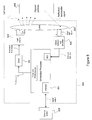
- FIG. 1 is a block diagram of an embodiment of the lighting system
- FIG. 2 shows an example of a reflected signal with accumulation and phase shift techniques wherein FIG. 2 a is a trace obtained with no accumulation and no phase shift, FIG. 2 b has accumulation and phase shift improvements and FIG. 2 c has a greater number of accumulations and phase shifts;
- FIG. 3 is a table of example setup parameters for the segmentation
- FIG. 4 shows an example of a reflected signal with adjusted parameters as a function of the distance
- FIG. 5 is a flow chart of an embodiment of the segmentation process
- FIG. 6 shows an example of the accumulation and phase shift technique for a 10 m range finder using the one sample by optical pulse technique
- FIG. 7 is a table of example setup configuration for the accumulation and phase shift technique using the one sample by optical pulse technique
- FIG. 8 is a block diagram of a lidar module using an embedded processor
- FIG. 9 shows a noisy signal fitted and filtered
- FIG. 10 presents a Gaussian pulse with a zero-crossing point of the first derivative
- FIG. 11 shows a typical PWM pattern with slope adjustment
- FIG. 12 shows a rising edge signal from a source and reflected signals
- FIG. 13 shows a 10% to 90% rising edge of an echo back noisy signal with linear regression
- FIG. 14 is a flow chart of an embodiment of the PWM edge technique for detection and ranging.
- FIG. 15 shows a rising edge with overshoot stabilizing after one cycle of the resonance frequency
- FIG. 16 shows a timing diagram of the method using an integration signal from the reflected signal and synchronized with rising edge and falling edge of the PWM lighting source
- FIG. 17 is a flow chart of the main steps of a method for acquiring a detected light optical signal and generating an accumulated digital trace
- FIG. 18 is a flow chart of the main steps of a method for detecting a distance to an object.
- FIG. 1 is a block diagram illustrating an embodiment of a lighting system equipped with the present system.
- the lighting system 100 has a visible-light source 112 .
- the visible-light source 12 has, as a first purpose, the emission of visible light for illumination or visual communication of information, like signaling, for human vision.
- the primary purpose of emitting light is controlled according to specific criteria like optical power, field of view and light color, to meet requirements defined through a number of regulations.
- the visible-light source 112 has one or more solid-state lighting devices, LEDs or OLEDs for instance.
- the visible-light source 112 is connected to a source controller 114 , so as to be driven into producing visible light.
- the system 100 performs detection of objects and particles (vehicles, passengers, pedestrians, airborne particles, gases and liquids) when these objects are part of the environment/scene illuminated by the light source 112 .
- the source controller 114 drives the visible-light source 112 in a predetermined mode, such that the emitted light takes the form of a light signal, for instance by way of amplitude-modulated or pulsed light emission.
- These light signals are such that they can be used to provide the lighting illumination level required by the application, through data/signal processor 118 and source controller 114 , while producing a detectable signal. Accordingly, it is possible to obtain a light level equivalent to a continuous light source by modulating the light signal fast enough (e.g., frequency more than 100 Hz) to be generally imperceptible to the human eye and having an average light power equivalent to a continuous light source.
- the light signal fast enough e.g., frequency more than 100 Hz
- the source controller 114 is designed to provide an illumination drive signal, such as a constant DC signal or a pulse-width modulated (PWM) signal, that is normally used in lighting systems to produce the required illumination and control its intensity.
- the illumination drive signal is produced by the illumination driver sub-module 114 A of the controller 114 .
- a modulated/pulsed driving signal supplies the fast modulation/pulse sequence required for remote object detection.
- This modulated/pulsed drive signal is produced by a modulation driver sub-module 114 B of the controller 114 .
- the amplitude of short-pulse (typ. ⁇ 50 ns) can be several time the nominal value while the duty cycle is low (typ. ⁇ 0.1%).
- the modulator driver 114 B can also be used to send data for optical communication. Both driving signals can be produced independently or in combination. Sequencing of the drive signals is controlled by the data/signal processor 118 .
- the light source 112 can be monitored by the optical detector 116 and the resulting parameters sent to the data/signal processor 118 for optimization of data processing.
- auxiliary light source (ALS) 122 can be a visible or non-visible source (e.g., UV or IR light, LEDs or laser) using the modulation driver 14 B.
- the auxiliary light source 122 provides additional capabilities for detecting objects and particles.
- UV light source (particularly around 250 nm) can be used to limit the impact of the sunlight when used with a UV detector.
- IR light can be used to increase the performance and the range of the detection area. IR lights and other types of light can be used to detect several types of particles by selecting specific wavelengths.
- the auxiliary light source 122 can also be useful during the installation of the system by using it as a pointer and distance meter reference. It can also be used to determine the condition of the lens.
- the visible-light source 112 is preferably made up of LEDs. More specifically, LEDs are well suited to be used in the lighting system 100 since LED intensity can be efficiently modulated/pulsed at suitable speed. Using this feature, current lighting systems already installed and featuring LEDs for standard lighting applications can be used as the light source 112 for detection applications, such as presence detection for energy savings, distance and speed measurements, fog, rain, snow or smoke detection and spectroscopic measurements for gas emission or smog detection.
- the system 100 has at least one lens 130 through which light is emitted in an appropriate way for specific applications.
- At least one input lens section 130 a of at least one lens 130 is used for receiving the light signal, for instance reflected or diffused (i.e., backscattered) by the objects/particles 134 .
- This input lens section 130 a can be at a single location or distributed (multiple zone elements) over the lens 130 and have at least one field of view.
- Several types of lens 130 can be used, such as Fresnel lenses for example.
- a sub-section of the lens 130 can be used for infrared wavelength.
- a sub-section of the lens 130 can be used for optical data reception.
- a detector 116 is associated with the visible-light source 112 and/or auxiliary light source 122 and the lens 130 .
- the detector module 116 is an optical detector (or detectors) provided so as to collect light emitted by the light source 112 /ALS 122 and back-scattered (reflected) by the objects/particles 134 .
- Detector module 116 can also monitor the visible-light source 112 or auxiliary light source 122 .
- the light signal can also come from an object 134 being the direct source of this light (such as a remote control) in order to send information to the data/signal processor through the optical detector module 116 .
- the optical detector module 116 is, for example, composed of photodiodes, avalanche photodiodes (APD), photomultipliers (PMT), complementary metal-oxide semiconductor (CMOS) or charge-coupled device (CCD) array sensors.
- Filters are typically provided with the detector module 116 to control background ambient light emitted from sources other than the lighting system 100 . Filters can also be used for spectroscopic measurements and to enhance performance of the light source 112 .
- a front-end and analog-to-digital converter (ADC) 124 is connected to detector 116 and receives detected light data therefrom and controls the detector 116 .
- adjusting the Vbias of an APD detector can be one of the detector controls to optimize the gain of the receiver section for an Automatic Gain Control (AGC).
- Analog filters can be used for discriminating specific frequencies or to measure the DC level.
- a detection and ranging digital processing unit 126 is connected to the front-end 124 , and controls parameters such as gain of amplifier, synchronization and sample rate of the ADC.
- the detection and ranging digital processing unit 126 receives data from ADC and pre-processes the data.
- the data/signal processor 118 is connected to the detection and ranging processing module 126 and receives pre-processed data.
- the data/signal processor 118 is also connected to the source controller 114 , so as to receive driving data therefrom.
- the data/signal processor 118 has a processing unit (e.g., CPU) so as to interpret the pre-processed data from the detection module 126 , in comparison with the driving data of the source controller 114 , which provides information about the predetermined mode of emission of the light signals emitted by the visible-light source 112 .
- a processing unit e.g., CPU
- information about the object e.g., presence, distance, speed of displacement, composition, dimension, etc.
- information about the object is calculated by the data/signal processor 118 as a function of the relationship (e.g., phase difference, relative intensity, spectral content, time of flight, etc.) between the driving data and the detected light data, is optionally pre-processed by the front-end and ADC 24 and the detection and ranging processing unit 126 .
- a database 120 may be provided in association with the data/signal processor 118 so as to provide historical data or tabulated data to accelerate the calculation of the object parameters.
- the data/signal processor 118 controls the source controller 114 and thus the light output of the visible-light source 112 .
- the visible-light source 112 may be required to increase or reduce its intensity, or change the parameters of its output. For example, changes in its output power can adapt the lighting level required in daytime conditions versus nighttime conditions or in bad visibility conditions such as fog, snow or rain.
- the system 100 can be provided with sensors 132 connected to the data/signal processor 118 .
- Sensors 132 can be an inclinometer, accelerometer, temperature sensor, day/night sensors, etc. Sensors 132 can be useful during the installation of the system and during operation of the system. For example, data from an inclinometer and accelerometer can be used to compensate for the impact on the field of view of an effect of the wind or any kind of vibration. Temperature sensors are useful to provide information about weather (internal, external or remote temperature with FIR lens).
- Information from sensors 132 and data/signal processor 118 and light from light source 112 and auxiliary light source 122 can be used during installation, in particular for adjusting the field of view of the optical receiver.
- the auxiliary light source 112 can be used as a pointer and distance meter.
- the system 100 has a power supply and interface 128 .
- the interface section is connected to a Data/signal processor and communicates to an external traffic management system (via wireless, power line, Ethernet, CAN bus, USB, etc.).
- ACC Adaptive Cruise Control
- the reflected signal is strong but, usually, the needs for a good resolution and fast refresh rate of the data are high.
- the reflected signal is weak and noisy but the need for resolution and refresh rate is less demanding.
- Phase shifting control techniques can improve accuracy using a digital acquisition system with low sample rate.
- a relatively low cost ADC ex.: 50 MSPS
- the detection and ranging digital processing unit 126 and the Data/signal Processor 118 allows to control the number of shift delay by period, the number of accumulation and the refresh rate for each data point sampled or for several segments. For shorter distances, with an echo back signal which is relatively strong, the number of shift delays and the refresh rate can be higher to improve the resolution and the response time. The number of accumulation (or other time-integration techniques) would be lower but sufficient at short distances (trade-off between signal-to-noise ratio, resolution and number of results per second).
- the accumulation technique improves the signal-to-noise ratio of the detected light signal using multiple measurements.
- the technique uses M light pulses and for each light pulse, a signal detected by the optical detector is sampled by the ADC with an ADC time resolution of 1/F second thereby generating M lidar traces of j points (S 1 to S j ) each. Points of the M lidar traces are added point per point to generate one accumulated digital lidar trace of j points.
- the phase shift technique is used to improve the time resolution of the trace acquired by the ADC and limited by its sample rate F Hz.
- the phase shift technique allows for the use of a low cost ADC having a low sample rate F by virtually increasing the effective sample rate.
- the effective sample rate is increased by a factor P by acquiring P sets corresponding to P light pulses while shifting the phase between the emitted light pulse and the ADC sampling rate.
- the phase shifting between each acquisition corresponds to 2 ⁇ /P.
- the P sets obtained are then combined in a single trace by interleaving the P sets such that the resulting trace is equivalent to a single measurement with a temporal resolution (1/F ⁇ P) second.
- the detection and ranging digital processing unit 126 and the Data/signal Processor 118 creates one combined trace of the reflected light pulse.
- the length of the buffer is at least j ⁇ P elements and the number of bit of each element is a function of the resolution of the ADC (number of bits, B) and the number of accumulations M.
- each element of the buffer should have at least B+log 2 M bits.
- FIGS. 2 a , 2 b and 2 c Example results of the accumulation and phase shift techniques are shown in FIGS. 2 a , 2 b and 2 c .
- a target is approximately at a distance of 12 meters and the system use an ADC at 50 MSPS.
- FIG. 2 a shows a trace obtained with no accumulation and no phase shift. The signal is noisy with a lack of resolution and it is very difficult to identify the target.
- FIG. 2 b shows an improvement in terms of signal to noise ratio by accumulating 64 sets with 8 shift delays.
- FIG. 2 c shows how an accumulation of 1024 sets with 256 shift delays can improve the signal-to-noise ratio and resolution.
- Accumulation and shift control can be done by a programmable logic, a Field Programmable Gate Array (FPGA) for example.
- Phase shifting can be controlled by delaying the clock of the ADC converter 130 by a fraction of a period or by delaying the driver of the optical source.
- FIG. 3 shows one example of setup configurations for this method using different parameters as a function of the distance. For different distances (for instance, for a range from 1 m to 100 m), one can optimize the temporal resolution, the number of accumulation and the refresh rate and make tradeoffs in terms of sensibility, accuracy and speed as a function of the distance to a target.
- FIG. 4 shows a reflected signal with a first echo from an object closer to the system and a second echo from another object further from the source.
- the amplitude of the first echo is higher and the system optimizes the temporal resolution.
- the amplitude of the second echo back pulse from the farther object is lower and the system optimizes the SNR by using more accumulation instead of optimizing the resolution.
- each parameter can be adaptive as a function of the echo back signal.
- the system can optimize the process by adjusting parameters as a function of the priority (resolution, refresh rate, SNR). For example, if the noise is lower than expected, the system can reduce the number of accumulation and increase the number of shift delays to improve the resolution.
- FIG. 5 shows a flow chart of a typical process for this method.
- Configuration 500 sets several parameters before the beginning of the process.
- Acquisition 502 starts the process by the synchronization of the emission of the optical pulses and the acquisition of samples by the ADC.
- Digital filtering and processing of the data 504 make the conditioning for the extraction and storage in memory of a lidar trace 506 .
- Detection and estimation of the distance 508 is made, typically using a reference signal and measuring the lapse of time between the emission and the reception of the signal.
- the transmission of the results 510 (the detection and the estimation of the distance) are transmitted to a external system.
- Noise analysis 512 is performed and an adjustment of the parameters as a function of the level of the noise 514 can be made to optimize the process.
- the ADC has to acquire samples at the frequency of the optical pulse emission.
- the ADC converts L samples per second with P shift delay of D ns of delay.
- FIG. 6 shows an example of that technique for a ten meter range finder.
- the ADC works at same frequency as the optical pulse driver (ex.: 100 KHz). For each one of the first twenty optical pulses, the system synchronizes a shift delay of 5 ns between the optical pulse driver and the ADC. After 20 pulses, the system samples the reflected back signal 95 ns after the pulse was emitted, just enough to detect the end of the reflected back signal from a target at 10 meters. For this example, if the system works at 100 KHz, after 200 us, a complete 10 meters Lidar trace is recorded. To improve the signal-to-noise ratio, one can accumulate up to 5000 times to have one complete lidar trace per second.
- FIG. 7 is a table showing setup configuration for this method. For a maximum range of 10 meters and 30 meters, the table shows tradeoffs between accuracy (temporal resolution), sensibility (improvement of the signal to noise ratio by accumulation) and speed (refresh rate).
- FIG. 8 shows a block diagram of a lidar module 800 using an embedded processor optimizing the cost of the range finder system.
- the embedded processor 801 controls the timing for the driver 802 sourcing the light source 803 .
- a light signal is emitted in a direction determined by the optical lens 804 .
- a reflection signal from objects/particles 834 is received on the optical lens 804 and collected by the optical detector and amplifier 805 .
- the embedded processor 801 uses an embedded ADC to make the acquisition of the lidar trace and processes the data and sends the information to an external system 840 .
- the system 800 can use several sources being driven sequentially using one sensor or several sensors. The frequency of acquisition is at the frequency of optical source multiplied by the number of optical sources.
- moving average techniques permit to constantly have the last N samples to perform an average.
- Using a FIFO by adding a new data and subtracting the first data accumulated is an example of an implementation of that technique.
- Averaging techniques can consider a signal from moving objects as noise and will fail to discriminate it. Frequency domain analysis can be useful for this kind of situation. Wavelet transform is very efficient for signal analysis in time/frequency domain and is sensitive to the transient signals. By separating the echo back signal in several segments and analyzing the spectral frequency, the system can detect the frequency of the pulse of the source in a specific segment. Averaging parameters can be adjusted as a function of events detected by the spectral analysis process. For instance, the number of averages should be reduced when moving objects are detected sequentially in different segments.
- Low pass filters can be used as pre-processes on each trace before averaging. Filters may be particularly efficient when more than one sample is available on an echo pulse. Information from noise analysis and from the information of the signal waveform emitted by the source can also help to discriminate a signal and to adjust the parameters. Specific processing functions can be used for each point of the trace or by segment.
- the reference signal can be a pattern signal stored in memory or a reference reflection signal of an optical pulse detected by a reference optical detector.
- This reference optical detector acquires a reference zero value and this reference signal is compared to the lidar trace. Detection and distance is based on comparison between both signals. Fit can be made by convolution.
- FIG. 9 shows a noisy signal fitted and filtered to diminish the effects of the noise.
- FIG. 9 presents the effect of signal filtering and curve fitting.
- the raw data curve is the noisy signal as received from the sensor.
- the filter curve is the raw data curve after filtering by correlation with an ideal (no noise) pulse. This removes the high-frequency noise.
- the fit curve presents the optimal fitting of an ideal pulse on the filtered signal. Fitting can improve distance stability especially when the signal is weak and still too noisy even after filtering.
- FIG. 10 shows an example of a Gaussian pulse with selected data over a predefined threshold and the result from the derivative calculation of those selected data. One can see the zero crossing from the derivative plot representing the peak of the pulse.
- Illumination Driver as a Source for Rangefinder with Edge Detection
- Switch-mode LED drivers are very useful notably for their efficiency compared to linear drivers.
- PWMs permit a very high dimming ratio without drifting the wavelength usually generated by linear drivers. Their performance is particularly well suited for high power LEDs.
- switch-mode LED drivers are noisier and the EMI can be an issue for some applications.
- One way to address this issue is to use a gate rising/falling slope adjust circuit to decrease the speed of transitions. Transitions at lower speed mean less EMI.
- FIG. 11 presents a typical PWM signal with slope adjustment.
- the PWM LED light source has a relatively constant slope during its rising/falling edge to reduce EMI (rising/falling edge of 100 ns for example).
- the optical signal from the source is sampled to be able to determine the starting time of the pulse (T 0 ).
- Electrical synchronization signal can also be used to indicate the starting point.
- the reflected signal is sampled with enough temporal resolution to have several points during the slope of the signal when an object in the field of view returns a perceptible echo.
- FIG. 12 shows an example of a rising edge from a source, an echo back signal from an object 4.5 meters away from the source ( ⁇ 30 ns later) and another from an object at 7 meters from the source ( ⁇ 45 ns later). Calculating the slope by linear regression or other means, an evaluation of the origin of the signal is made and the elapsed time between the signal from the source and an echo back signal can be determined. Based on that result, one can estimate the presence and the distance of the object reflecting the signal.
- FIG. 13 represents a 10% to 90% rising edge of an echo back noisy signal from an object at 4.5 meters from the source.
- linear regression one can calculate the intercept point and get a good estimate of the delay between the two signals. Samples close to the end of the slope have a better SNR.
- a threshold can be set to discriminate the presence or the absence of an object.
- Averaging and filtering techniques can be used to diminish the level of noise and shifting techniques can also be used to have more points in the slope. As shown in FIG. 9 , even with a noisy signal, this method can give good results.
- FIG. 14 shows a flow chart of the typical process for this method.
- the echo back signal is filtered 1400 , typically using a band-pass filter based on the frequency of the transition. Rising and falling edges are detected 1402 and samples are taken in the slope 1404 to memorize a digital waveform of the slope.
- the calculation of the linear regression 1406 is made and permits to calculate the intercept point 1408 . Based on that information, the calculation of the difference in time between the signal emission and the signal received 1410 allows to estimate the distance to the object 1412 .
- This method can be improved by using demodulation and spectral analysis techniques.
- the base frequency of the PWM can be demodulated and the result of this demodulation will give an indication of a presence of an object.
- By selecting a frequency based on an harmonic coming from the slopes of the PWM signal one can estimate the position of the object by spectral analysis of different segments. Knowing the approximated position, the acquisition of samples will be adjusted to target the rising and the falling edge.
- the edge detection technique By using the edge detection technique, one can use a standard LED driver for the purpose of lighting and also for the purpose of detection and ranging.
- the frequency of the PWM might be in the range from a few KHz up to 1 MHz. High frequency modulation can improve the SNR notably by averaging techniques.
- this method permits using a PWM source for a LED lighting system completely electrically isolated from the receiver.
- EMI is not an issue
- the electronic driver can generate a fast rising edge and/or falling edge with some overshoot at a resonance frequency. This signal adds more power at a specific frequency and increase the signal that can be detected by the receiver.
- FIG. 15 shows a rising edge with overshoot stabilizing after one cycle of the resonance frequency.
- Different shapes of objects reflect a modified waveform of the original signal.
- the echo back signal from a wall is different when compared to the echo back signal from an object with an irregular shape. Reflection from two objects with a short longitudinal distance between them also generates a distinct waveform.
- this data can be used to improve the digital processing performance.
- Digital correlation can be done to detect a predetermined pattern.
- Averaging techniques do not perform very well with moving objects. By tracking a moving object, one can anticipate the position of the object and adapt to the situation. Averaging with shifting proportional to the estimated position is a way to improve the SNR even in the case of moving objects. Tracking edges is another way to adjust the acquisition of the waveform with more points in the region of interest. Spectral analysis can also be used to lock and track an object.
- the system can be used as a road weather information system (RWIS) and thus provide information about temperature, visibility (fog, snow, rain, dust), condition of the road (icy) and pollution (smog). Pattern recognition based on low frequency signals and spikes can be implemented to do so. The recognition of bad weather condition patterns helps to discriminate noise from objects.
- the system can be used to adjust the intensity of light depending on weather conditions. Monitoring the condition of the lens is also possible (dirt, accumulation of snow, etc). This monitoring can be done by the measurement of the reflection on the lens from the source or from an auxiliary source.
- FIG. 16 shows a timing diagram of the method using an integration signal from the reflected signal and synchronized with the rising edge and the falling edge of the PWM lighting source.
- FIG. 16 shows a PWM signal (PWM curve 1601 ) with an adjustable duty cycle to control the intensity of light for illumination purposes.
- PWM curve 1601 a PWM signal with an adjustable duty cycle to control the intensity of light for illumination purposes.
- the sensor starts the integration (sensor integration curve 1603 ) of the reflected signal.
- the sensor stops the integration.
- the same process is performed at the falling edge of the PWM.
- the light pulse from the source is delayed (delay curve 1602 ) proportionally to the travelled distance.
- the delta curve 1604 shows that the integration P 1 for the rising edge is smaller than the integration P 2 for the falling edge because of the delay of travel of the light signal. In fact, if an object is very close to the source, the integration value from the rising edge will be approximately equal to the integration value from the falling edge. But, if an object is further, the integration value of rising edge will be less than the integration value of the falling edge. The difference between the values is proportional to the distance.
- the same technique can be used by switching the synchronisation of the signal of the optical source and the signal to the sensor integration time.
- Values from the signal integration are memorized.
- each “pixel” is memorized.
- Several integrations can be performed and an averaging process can be done to improve signal to noise ratio.
- the combined trace can be compared 1720 to a detected reference reflection signal of the pulse to determine 1722 a distance traveled by the pulse.
- a timer can be triggered to calculate a time elapsed 1724 between the emission of the pulse and the detection of the reflection signal to determine a distance traveled 1722 by the pulse based on the time elapsed.
- the method comprises providing a lighting system 1800 having at least one pulse width modulated visible-light source for illumination of a field of view; emitting an illumination signal 1802 for illuminating the field of view for a duration of time y using the visible-light source at a time t; integrating a reflection energy for a first time period from a time t ⁇ x to a time t+x 1808 ; determining a first integration value for the first time period 1810 ; integrating the reflection energy for a second time period from a time t+y ⁇ x to a time t+y+x 1812 ; determining a second integration value for the second time period 1814 ; calculating a difference value between the first integration value and the second integration value 1816 ; determining a propagation delay value proportional to the difference value 1818 ; determining the distance to the object from the propagation delay value 1820 .
Abstract
Description
Distance=c×(INT/4)*(P2−P1)/(P2+P1),
where c represents the velocity of light, INT represents the integration time, P1 represents the integration value synchronized with the rising edge of the optical pulse and P2 represents the integration value synchronized on the falling edge of the optical pulse.
Distance=c×(INT/4)*((P2−B)−(P1−B))/(P2+P1−2B),
where B is the integration value of the optical background level when the optical source of the system is off.
Distance=c×(INT/4)*(P1−P2)/(P2+P1),
where c represents the velocity of light, INT represents the integration time, P1 represents the integration value when optical pulse is synchronized with the rising edge of integration and P2 represents the integration value when the optical pulse is synchronized with the falling edge of integration.
Distance=c×(INT/4)*((P1−B)−(P2−B))/(P2+P1−2B).
Claims (3)
Priority Applications (3)
| Application Number | Priority Date | Filing Date | Title |
|---|---|---|---|
| US13/632,191 US8619241B2 (en) | 2007-12-21 | 2012-10-01 | Distance detection method and system |
| US14/984,704 USRE46930E1 (en) | 2007-12-21 | 2015-12-30 | Distance detection method and system |
| US16/011,820 USRE49342E1 (en) | 2007-12-21 | 2018-06-19 | Distance detection method and system |
Applications Claiming Priority (6)
| Application Number | Priority Date | Filing Date | Title |
|---|---|---|---|
| US1586707P | 2007-12-21 | 2007-12-21 | |
| US1573807P | 2007-12-21 | 2007-12-21 | |
| US4242408P | 2008-04-04 | 2008-04-04 | |
| US12/809,235 US8310655B2 (en) | 2007-12-21 | 2008-12-19 | Detection and ranging methods and systems |
| PCT/CA2008/002268 WO2009079789A1 (en) | 2007-12-21 | 2008-12-19 | Detection and ranging methods and systems |
| US13/632,191 US8619241B2 (en) | 2007-12-21 | 2012-10-01 | Distance detection method and system |
Related Parent Applications (4)
| Application Number | Title | Priority Date | Filing Date |
|---|---|---|---|
| US12/809,235 Division US8310655B2 (en) | 2007-12-21 | 2008-12-19 | Detection and ranging methods and systems |
| PCT/CA2008/002268 Division WO2009079789A1 (en) | 2007-12-21 | 2008-12-19 | Detection and ranging methods and systems |
| US12809235 Division | 2010-06-18 | ||
| US14/984,704 Continuation USRE46930E1 (en) | 2007-12-21 | 2015-12-30 | Distance detection method and system |
Related Child Applications (2)
| Application Number | Title | Priority Date | Filing Date |
|---|---|---|---|
| US14/984,704 Reissue USRE46930E1 (en) | 2007-12-21 | 2015-12-30 | Distance detection method and system |
| US16/011,820 Reissue USRE49342E1 (en) | 2007-12-21 | 2018-06-19 | Distance detection method and system |
Publications (2)
| Publication Number | Publication Date |
|---|---|
| US20130044310A1 US20130044310A1 (en) | 2013-02-21 |
| US8619241B2 true US8619241B2 (en) | 2013-12-31 |
Family
ID=40800622
Family Applications (3)
| Application Number | Title | Priority Date | Filing Date |
|---|---|---|---|
| US12/809,235 Active 2029-10-17 US8310655B2 (en) | 2007-12-21 | 2008-12-19 | Detection and ranging methods and systems |
| US13/632,191 Ceased US8619241B2 (en) | 2007-12-21 | 2012-10-01 | Distance detection method and system |
| US16/011,820 Active USRE49342E1 (en) | 2007-12-21 | 2018-06-19 | Distance detection method and system |
Family Applications Before (1)
| Application Number | Title | Priority Date | Filing Date |
|---|---|---|---|
| US12/809,235 Active 2029-10-17 US8310655B2 (en) | 2007-12-21 | 2008-12-19 | Detection and ranging methods and systems |
Family Applications After (1)
| Application Number | Title | Priority Date | Filing Date |
|---|---|---|---|
| US16/011,820 Active USRE49342E1 (en) | 2007-12-21 | 2018-06-19 | Distance detection method and system |
Country Status (5)
| Country | Link |
|---|---|
| US (3) | US8310655B2 (en) |
| EP (2) | EP2235561B8 (en) |
| JP (3) | JP5671345B2 (en) |
| CA (2) | CA2857826C (en) |
| WO (1) | WO2009079789A1 (en) |
Cited By (12)
| Publication number | Priority date | Publication date | Assignee | Title |
|---|---|---|---|---|
| US20150170517A1 (en) * | 2013-12-12 | 2015-06-18 | Chen Yan | Vehicle parking management system with guidance for indicating floor vacant vehicular parking dock |
| US9360554B2 (en) | 2014-04-11 | 2016-06-07 | Facet Technology Corp. | Methods and apparatus for object detection and identification in a multiple detector lidar array |
| US9866816B2 (en) | 2016-03-03 | 2018-01-09 | 4D Intellectual Properties, Llc | Methods and apparatus for an active pulsed 4D camera for image acquisition and analysis |
| US10036801B2 (en) | 2015-03-05 | 2018-07-31 | Big Sky Financial Corporation | Methods and apparatus for increased precision and improved range in a multiple detector LiDAR array |
| US10203399B2 (en) | 2013-11-12 | 2019-02-12 | Big Sky Financial Corporation | Methods and apparatus for array based LiDAR systems with reduced interference |
| WO2019234180A1 (en) | 2018-06-08 | 2019-12-12 | Osram Opto Semiconductors Gmbh | Apparatus and headlight |
| US10520592B2 (en) | 2016-12-31 | 2019-12-31 | Waymo Llc | Light detection and ranging (LIDAR) device with an off-axis receiver |
| US20200371236A1 (en) * | 2018-02-15 | 2020-11-26 | Denso Corporation | Distance measurement apparatus |
| US20210141052A1 (en) * | 2019-11-08 | 2021-05-13 | Richwave Technology Corp. | Radar and Method of Updating Background Components of Echo Signal of Radar |
| US11175006B2 (en) | 2018-09-04 | 2021-11-16 | Udayan Kanade | Adaptive lighting system for even illumination |
| USRE49342E1 (en) | 2007-12-21 | 2022-12-20 | Leddartech Inc. | Distance detection method and system |
| US11635496B2 (en) | 2019-09-10 | 2023-04-25 | Analog Devices International Unlimited Company | Data reduction for optical detection |
Families Citing this family (83)
| Publication number | Priority date | Publication date | Assignee | Title |
|---|---|---|---|---|
| US8242476B2 (en) | 2005-12-19 | 2012-08-14 | Leddartech Inc. | LED object detection system and method combining complete reflection traces from individual narrow field-of-view channels |
| US8436748B2 (en) | 2007-06-18 | 2013-05-07 | Leddartech Inc. | Lighting system with traffic management capabilities |
| EP2160629B1 (en) | 2007-06-18 | 2017-04-26 | Leddartech Inc. | Lighting system with driver assistance capabilities |
| EP2232462B1 (en) | 2007-12-21 | 2015-12-16 | Leddartech Inc. | Parking management system and method using lighting system |
| WO2009136184A2 (en) * | 2008-04-18 | 2009-11-12 | Bae Systems Plc | Improvements in lidars |
| WO2011073888A2 (en) | 2009-12-14 | 2011-06-23 | Montel Inc. | Entity detection system and method for monitoring an area |
| CA2782180C (en) | 2009-12-22 | 2015-05-05 | Leddartech Inc. | Active 3d monitoring system for traffic detection |
| WO2012011037A1 (en) | 2010-07-23 | 2012-01-26 | Leddartech Inc. | 3d optical detection system and method for a mobile storage system |
| US8908159B2 (en) * | 2011-05-11 | 2014-12-09 | Leddartech Inc. | Multiple-field-of-view scannerless optical rangefinder in high ambient background light |
| US9378640B2 (en) | 2011-06-17 | 2016-06-28 | Leddartech Inc. | System and method for traffic side detection and characterization |
| GB2492848A (en) * | 2011-07-15 | 2013-01-16 | Softkinetic Sensors Nv | Optical distance measurement |
| US9069061B1 (en) | 2011-07-19 | 2015-06-30 | Ball Aerospace & Technologies Corp. | LIDAR with analog memory |
| US20150071566A1 (en) * | 2011-07-22 | 2015-03-12 | Raytheon Company | Pseudo-inverse using weiner-levinson deconvolution for gmapd ladar noise reduction and focusing |
| DE202011105139U1 (en) * | 2011-08-29 | 2011-11-30 | Robert Bosch Gmbh | rangefinder |
| US8988081B2 (en) | 2011-11-01 | 2015-03-24 | Teradyne, Inc. | Determining propagation delay |
| CN103245938B (en) * | 2012-02-14 | 2017-11-14 | 英特赛尔美国有限公司 | The optical proximity sensor of one or more objects is detected using ECT echo cancellation technique |
| US8994926B2 (en) * | 2012-02-14 | 2015-03-31 | Intersil Americas LLC | Optical proximity sensors using echo cancellation techniques to detect one or more objects |
| JP6021670B2 (en) * | 2012-02-16 | 2016-11-09 | オリンパス株式会社 | Endoscope system and A / D converter |
| EP2820632B8 (en) | 2012-03-02 | 2017-07-26 | Leddartech Inc. | System and method for multipurpose traffic detection and characterization |
| DE102012106149A1 (en) * | 2012-07-09 | 2014-01-09 | Endress + Hauser Gmbh + Co. Kg | Method and device for the laser-based determination of the filling level of a filling material in a container |
| EP2703837B1 (en) * | 2012-09-03 | 2014-07-16 | Sick Ag | Safety laser scanner |
| IN2015DN02057A (en) * | 2012-09-13 | 2015-08-14 | Mbda Uk Ltd | |
| DE102013100367A1 (en) * | 2013-01-15 | 2014-07-17 | Sick Ag | Distance measuring optoelectronic sensor and method for determining the distance of objects |
| US9304203B1 (en) * | 2013-03-13 | 2016-04-05 | Google Inc. | Methods, devices, and systems for improving dynamic range of signal receiver |
| US9671489B1 (en) * | 2013-03-15 | 2017-06-06 | Epitaxial Technologies, Llc | Electromagnetic sensor and optical detection system for detecting angle of arrival of optical signals and a range of a source of the optical signals |
| US20160153277A1 (en) * | 2013-08-07 | 2016-06-02 | Halliburton Energy Services, Inc. | Monitoring a well flow device by fiber optic sensing |
| US9250714B2 (en) * | 2013-11-27 | 2016-02-02 | Intersil Americas LLC | Optical proximity detectors |
| US20150168163A1 (en) * | 2013-12-12 | 2015-06-18 | Douglas Chase | Method for enhanced gps navigation |
| US11471697B2 (en) * | 2015-02-10 | 2022-10-18 | Andrew Hewitson | Laser therapy device and method of use |
| US9606228B1 (en) | 2014-02-20 | 2017-03-28 | Banner Engineering Corporation | High-precision digital time-of-flight measurement with coarse delay elements |
| US11243294B2 (en) | 2014-05-19 | 2022-02-08 | Rockwell Automation Technologies, Inc. | Waveform reconstruction in a time-of-flight sensor |
| US9256944B2 (en) | 2014-05-19 | 2016-02-09 | Rockwell Automation Technologies, Inc. | Integration of optical area monitoring with industrial machine control |
| US9921300B2 (en) * | 2014-05-19 | 2018-03-20 | Rockwell Automation Technologies, Inc. | Waveform reconstruction in a time-of-flight sensor |
| US9696424B2 (en) | 2014-05-19 | 2017-07-04 | Rockwell Automation Technologies, Inc. | Optical area monitoring with spot matrix illumination |
| US11143749B2 (en) | 2014-05-23 | 2021-10-12 | Signify Holding B.V. | Object detection system and method |
| CA2960123C (en) | 2014-09-09 | 2021-04-13 | Leddartech Inc. | Discretization of detection zone |
| US9625108B2 (en) | 2014-10-08 | 2017-04-18 | Rockwell Automation Technologies, Inc. | Auxiliary light source associated with an industrial application |
| US9977512B2 (en) | 2014-10-24 | 2018-05-22 | Intersil Americas LLC | Open loop correction for optical proximity detectors |
| US10795005B2 (en) | 2014-12-09 | 2020-10-06 | Intersil Americas LLC | Precision estimation for optical proximity detectors |
| JP6519238B2 (en) * | 2015-03-11 | 2019-05-29 | サンケン電気株式会社 | Current detection circuit |
| US10419655B2 (en) | 2015-04-27 | 2019-09-17 | Snap-Aid Patents Ltd. | Estimating and using relative head pose and camera field-of-view |
| US9642215B2 (en) * | 2015-07-28 | 2017-05-02 | Intersil Americas LLC | Optical sensors that compensate for ambient light and interference light |
| US10408926B2 (en) | 2015-09-18 | 2019-09-10 | Qualcomm Incorporated | Implementation of the focal plane 2D APD array for hyperion lidar system |
| US9992477B2 (en) | 2015-09-24 | 2018-06-05 | Ouster, Inc. | Optical system for collecting distance information within a field |
| US10063849B2 (en) | 2015-09-24 | 2018-08-28 | Ouster, Inc. | Optical system for collecting distance information within a field |
| US11255663B2 (en) | 2016-03-04 | 2022-02-22 | May Patents Ltd. | Method and apparatus for cooperative usage of multiple distance meters |
| JP6641006B2 (en) * | 2016-06-02 | 2020-02-05 | シャープ株式会社 | Optical sensors and electronic devices |
| KR20230074300A (en) | 2016-08-24 | 2023-05-26 | 아우스터, 인크. | Optical system for collecting distance information within a field |
| US20180172807A1 (en) * | 2016-12-20 | 2018-06-21 | Analog Devices Global | Method of Providing Enhanced Range Accuracy |
| DE102017101945A1 (en) * | 2017-02-01 | 2018-08-02 | Osram Opto Semiconductors Gmbh | Measuring arrangement with an optical transmitter and an optical receiver |
| WO2018183715A1 (en) * | 2017-03-29 | 2018-10-04 | Luminar Technologies, Inc. | Method for controlling peak and average power through laser receiver |
| DE202018006695U1 (en) | 2017-05-15 | 2022-04-01 | Ouster, Inc. | Optical image transmitter with brightness enhancement |
| DE102017005395B4 (en) * | 2017-06-06 | 2019-10-10 | Blickfeld GmbH | LIDAR distance measurement with scanner and FLASH light source |
| US11543503B2 (en) | 2017-06-07 | 2023-01-03 | Hesai Technology Co., Ltd. | Multi-line laser radar |
| DE102017112955A1 (en) * | 2017-06-13 | 2018-12-13 | Automotive Lighting Reutlingen Gmbh | Bifunctional light module for a motor vehicle headlamp with Lidar function |
| DE102017211141A1 (en) * | 2017-06-30 | 2019-01-03 | Osram Gmbh | EFFECT LIGHT, LUMINAIRE GROUP, ARRANGEMENT AND PROCEDURE |
| US10564219B2 (en) | 2017-07-27 | 2020-02-18 | Teradyne, Inc. | Time-aligning communication channels |
| US10677899B2 (en) * | 2017-08-07 | 2020-06-09 | Waymo Llc | Aggregating non-imaging SPAD architecture for full digital monolithic, frame averaging receivers |
| US10852438B2 (en) * | 2017-08-21 | 2020-12-01 | Caterpillar Inc. | LIDAR waveform classification |
| US10914824B2 (en) * | 2017-11-21 | 2021-02-09 | Analog Devices International Unlimited Company | Systems and methods for measuring a time of flight in a lidar system |
| DE102017221784A1 (en) * | 2017-12-04 | 2019-06-06 | Osram Gmbh | Method of operating a lidar sensor, lidar sensor and means of locomotion |
| US10481269B2 (en) | 2017-12-07 | 2019-11-19 | Ouster, Inc. | Rotating compact light ranging system |
| CN111758045A (en) | 2018-01-03 | 2020-10-09 | 混合雷达系统公司 | Apparatus and method for measuring signal transmission time between two events |
| EP3540991B1 (en) | 2018-03-13 | 2021-07-28 | ABB Schweiz AG | Intelligent electronic device comprising a cellular radio module |
| US10760957B2 (en) | 2018-08-09 | 2020-09-01 | Ouster, Inc. | Bulk optics for a scanning array |
| US10739189B2 (en) | 2018-08-09 | 2020-08-11 | Ouster, Inc. | Multispectral ranging/imaging sensor arrays and systems |
| JP2020034456A (en) * | 2018-08-30 | 2020-03-05 | パイオニア株式会社 | Signal processing device |
| JP2020034455A (en) * | 2018-08-30 | 2020-03-05 | パイオニア株式会社 | Map data structure |
| US11513198B2 (en) * | 2019-01-04 | 2022-11-29 | Waymo Llc | LIDAR pulse elongation |
| EP3696572A1 (en) * | 2019-02-13 | 2020-08-19 | Infineon Technologies AG | Method, apparatus and computer program for detecting a presence of airborne particles |
| GB201902508D0 (en) | 2019-02-25 | 2019-04-10 | Intersurgical Ag | Improvements relating to humidifiers for respiratory gases |
| US11947041B2 (en) | 2019-03-05 | 2024-04-02 | Analog Devices, Inc. | Coded optical transmission for optical detection |
| EP3936896A4 (en) * | 2019-03-29 | 2022-02-23 | Huawei Technologies Co., Ltd. | Distance measurement method and device based on detection signal |
| US11698641B2 (en) * | 2019-04-26 | 2023-07-11 | GM Global Technology Operations LLC | Dynamic lidar alignment |
| JP7240947B2 (en) | 2019-05-09 | 2023-03-16 | 株式会社アドバンテスト | Optical test equipment |
| DE102019215835A1 (en) * | 2019-10-15 | 2021-04-15 | Robert Bosch Gmbh | Expansion of a dynamic range of SPAD-based detectors |
| US20210253048A1 (en) * | 2020-02-14 | 2021-08-19 | Magna Electronics Inc. | Vehicular sensing system with variable power mode for thermal management |
| WO2022016276A1 (en) | 2020-07-21 | 2022-01-27 | Leddartech Inc. | Beam-steering device particularly for lidar systems |
| WO2022016277A1 (en) | 2020-07-21 | 2022-01-27 | Leddartech Inc. | Systems and methods for wide-angle lidar using non-uniform magnification optics |
| US11828853B2 (en) | 2020-07-21 | 2023-11-28 | Leddartech Inc. | Beam-steering device particularly for LIDAR systems |
| AU2021371019A1 (en) * | 2020-10-30 | 2023-06-15 | Nalu Scientific, LLC | System and method for high dynamic range waveform digitization |
| EP4285146A1 (en) * | 2021-09-17 | 2023-12-06 | Banner Engineering Corporation | Time of flight detection systems with efficient phase measurement |
| JP7233628B1 (en) * | 2022-09-30 | 2023-03-06 | 三菱電機株式会社 | light controller |
Citations (25)
| Publication number | Priority date | Publication date | Assignee | Title |
|---|---|---|---|---|
| US4808997A (en) | 1987-05-21 | 1989-02-28 | Barkley George J | Photoelectric vehicle position indicating device for use in parking and otherwise positioning vehicles |
| US4891624A (en) | 1987-06-12 | 1990-01-02 | Stanley Electric Co., Ltd. | Rearward vehicle obstruction detector using modulated light from the brake light elements |
| JPH04145391A (en) | 1990-10-05 | 1992-05-19 | Mitsubishi Electric Corp | Distance measuring device |
| JPH04145390A (en) | 1990-10-05 | 1992-05-19 | Mitsubishi Electric Corp | Distance measuring device |
| US5633801A (en) | 1995-10-11 | 1997-05-27 | Fluke Corporation | Pulse-based impedance measurement instrument |
| US5812249A (en) | 1996-09-26 | 1998-09-22 | Envirotest Systems Corporation | Speed and acceleration monitoring device using visible laser beams |
| US6502053B1 (en) | 2000-06-12 | 2002-12-31 | Larry Hardin | Combination passive and active speed detection system |
| US20040035620A1 (en) | 2002-08-26 | 2004-02-26 | Mckeefery James | Single wire automatically navigated vehicle systems and methods for toy applications |
| US20040135992A1 (en) | 2002-11-26 | 2004-07-15 | Munro James F. | Apparatus for high accuracy distance and velocity measurement and methods thereof |
| US6765495B1 (en) | 2000-06-07 | 2004-07-20 | Hrl Laboratories, Llc | Inter vehicle communication system |
| US6850156B2 (en) | 1999-11-15 | 2005-02-01 | Donnelly Corporation | Anti-collision safety system for vehicle |
| US20050117364A1 (en) | 2003-10-27 | 2005-06-02 | Mark Rennick | Method and apparatus for projecting a turn signal indication |
| JP2005170184A (en) | 2003-12-10 | 2005-06-30 | Nissan Motor Co Ltd | Light emitting diode lamp device with radar function |
| US20050269481A1 (en) * | 2002-08-05 | 2005-12-08 | Elbit Systems Ltd. | Vehicle mounted night vision imaging system and method |
| US20060147089A1 (en) | 2005-01-04 | 2006-07-06 | Deere & Company, A Delaware Corporation | Method and system for guiding a vehicle with vision-based adjustment |
| US20060149472A1 (en) | 2005-01-04 | 2006-07-06 | Deere & Company, A Delaware Corporation. | Vision-aided system and method for guiding a vehicle |
| US20070091294A1 (en) | 2003-10-06 | 2007-04-26 | Triple-In Holding Ag | Distance measurement |
| JP2007121116A (en) | 2005-10-28 | 2007-05-17 | Sharp Corp | Optical distance measuring device |
| US7221271B2 (en) | 2002-10-31 | 2007-05-22 | Gerd Reime | Device for controlling lighting for the interiors of automotive vehicles and method for controlling said device |
| US7350945B2 (en) | 2004-01-09 | 2008-04-01 | Valeo Vision | System and method of detecting driving conditions for a motor vehicle |
| US7417718B2 (en) | 2005-10-28 | 2008-08-26 | Sharp Kabushiki Kaisha | Optical distance measuring apparatus |
| US20090102699A1 (en) | 2007-10-11 | 2009-04-23 | Andreas Behrens | Method for Detecting and Documenting Traffic Violations at a Traffic Light |
| US20090251680A1 (en) | 2008-04-02 | 2009-10-08 | Ali Farsaie | Three dimensional spatial imaging system and method |
| US7957900B2 (en) | 2008-02-08 | 2011-06-07 | Gaurav Chowdhary | Tracking vehicle locations in a parking lot for definitive display on a GUI |
| US20110134249A1 (en) | 2009-12-04 | 2011-06-09 | Lockheed Martin Corporation | Optical Detection and Ranging Sensor System For Sense and Avoid, and Related Methods |
Family Cites Families (216)
| Publication number | Priority date | Publication date | Assignee | Title |
|---|---|---|---|---|
| US3045231A (en) * | 1958-04-17 | 1962-07-17 | Thompson Ramo Wooldridge Inc | Signal analyzing method and system |
| DE2002012A1 (en) | 1969-01-21 | 1970-08-13 | Del Signore Dr Giovanni | Device and method for reporting obstacles and for displaying the distance of the obstacles |
| DE2229887C3 (en) * | 1972-06-19 | 1980-07-17 | Siemens Ag, 1000 Berlin Und 8000 Muenchen | Distance measuring device with a laser working as a transmitter and its application for speed measurement |
| DE3215845C1 (en) * | 1982-04-28 | 1983-11-17 | Eltro GmbH, Gesellschaft für Strahlungstechnik, 6900 Heidelberg | Distance sensor for a projectile igniter |
| US4717862A (en) | 1984-11-19 | 1988-01-05 | The United States Government As Represented By The Secretary Of The Navy | Pulsed illumination projector |
| US4766421A (en) | 1986-02-19 | 1988-08-23 | Auto-Sense, Ltd. | Object detection apparatus employing electro-optics |
| GB8727824D0 (en) | 1987-11-27 | 1987-12-31 | Combustion Dev Ltd | Monitoring means |
| GB8826624D0 (en) | 1988-11-14 | 1988-12-21 | Martell D K | Traffic congestion monitoring system |
| US4928232A (en) | 1988-12-16 | 1990-05-22 | Laser Precision Corporation | Signal averaging for optical time domain relectometers |
| KR930006797B1 (en) * | 1989-10-16 | 1993-07-23 | 후지쓰 가부시끼가이샤 | Article detection method and device |
| GB8925384D0 (en) * | 1989-11-09 | 1989-12-28 | Ongar Enterprises Ltd | Vehicle spacing system |
| US5134393A (en) | 1990-04-02 | 1992-07-28 | Henson H Keith | Traffic control system |
| GB9018174D0 (en) | 1990-08-17 | 1990-10-03 | Pearpoint Ltd | Apparatus for reading vehicle number-plates |
| EP0476562A3 (en) | 1990-09-19 | 1993-02-10 | Hitachi, Ltd. | Method and apparatus for controlling moving body and facilities |
| JPH04172285A (en) * | 1990-11-02 | 1992-06-19 | Mitsubishi Electric Corp | Distance measuring apparatus |
| US5179286A (en) * | 1990-10-05 | 1993-01-12 | Mitsubishi Denki K.K. | Distance measuring apparatus receiving echo light pulses |
| FR2671653B1 (en) | 1991-01-11 | 1995-05-24 | Renault | MOTOR VEHICLE TRAFFIC MEASUREMENT SYSTEM. |
| US5357331A (en) * | 1991-07-02 | 1994-10-18 | Flockencier Stuart W | System for processing reflected energy signals |
| US5102218A (en) | 1991-08-15 | 1992-04-07 | The United States Of America As Represented By The Secretary Of The Air Force | Target-aerosol discrimination by means of digital signal processing |
| GB2264411B (en) | 1992-02-13 | 1995-09-06 | Roke Manor Research | Active infrared detector system |
| FR2690519B1 (en) | 1992-04-23 | 1994-06-10 | Est Centre Etu Tech Equipement | DEVICE FOR ANALYZING THE PATH OF MOBILES. |
| US5298905A (en) * | 1992-06-12 | 1994-03-29 | Motorola, Inc. | Visible light detection and ranging apparatus and method |
| US5546188A (en) | 1992-11-23 | 1996-08-13 | Schwartz Electro-Optics, Inc. | Intelligent vehicle highway system sensor and method |
| DE4337872C2 (en) * | 1992-12-22 | 1998-04-30 | Mitsubishi Electric Corp | Distance measuring device and vehicle speed control device for maintaining an inter-vehicle distance |
| DE4304298A1 (en) | 1993-02-15 | 1994-08-18 | Atlas Elektronik Gmbh | Method for classifying vehicles passing a given waypoint |
| US5510800A (en) | 1993-04-12 | 1996-04-23 | The Regents Of The University Of California | Time-of-flight radio location system |
| US5389921A (en) | 1993-05-17 | 1995-02-14 | Whitton; John M. | Parking lot apparatus and method |
| US5565870A (en) * | 1993-06-28 | 1996-10-15 | Nissan Motor Co., Ltd. | Radar apparatus with determination of presence of target reflections |
| US5471215A (en) * | 1993-06-28 | 1995-11-28 | Nissan Motor Co., Ltd. | Radar apparatus |
| US5396510A (en) * | 1993-09-30 | 1995-03-07 | Honeywell Inc. | Laser sensor capable of measuring distance, velocity, and acceleration |
| US5381155A (en) | 1993-12-08 | 1995-01-10 | Gerber; Eliot S. | Vehicle speeding detection and identification |
| US5552767A (en) | 1994-02-14 | 1996-09-03 | Toman; John R. | Assembly for, and method of, detecting and signalling when an object enters a work zone |
| US5714754A (en) | 1994-03-04 | 1998-02-03 | Nicholas; John Jacob | Remote zone operation of lighting systems for above-ground enclosed or semi-enclosed parking structures |
| JPH07280940A (en) * | 1994-04-12 | 1995-10-27 | Mitsubishi Electric Corp | Radar for vehicle |
| US7630806B2 (en) * | 1994-05-23 | 2009-12-08 | Automotive Technologies International, Inc. | System and method for detecting and protecting pedestrians |
| JPH07333339A (en) | 1994-06-03 | 1995-12-22 | Mitsubishi Electric Corp | Obstacle detector for automobile |
| US5519209A (en) * | 1994-06-15 | 1996-05-21 | Alliedsignal Inc. | High range resolution active imaging system using a high speed shutter and a light pulse having a sharp edge |
| JP3185547B2 (en) * | 1994-06-28 | 2001-07-11 | 三菱電機株式会社 | Distance measuring device |
| EP0716297B1 (en) | 1994-11-26 | 1998-04-22 | Hewlett-Packard GmbH | Optical time domain reflectometer and method for time domain reflectometry |
| US5633629A (en) | 1995-02-08 | 1997-05-27 | Hochstein; Peter A. | Traffic information system using light emitting diodes |
| DE19604338B4 (en) | 1995-02-18 | 2004-07-15 | Leich, Andreas, Dipl.-Ing. | Vehicle counting and classification device |
| US6259862B1 (en) | 1995-04-11 | 2001-07-10 | Eastman Kodak Company | Red-eye reduction using multiple function light source |
| KR0150110B1 (en) | 1995-04-21 | 1998-12-15 | 이호림 | Permanent pool cavity seal for nuclear reactor |
| EP0823036A4 (en) | 1995-04-28 | 1999-09-15 | Schwartz Electro Optics Inc | Intelligent vehicle highway system sensor and method |
| DE19517001A1 (en) | 1995-05-09 | 1996-11-14 | Sick Optik Elektronik Erwin | Method and device for determining the light propagation time over a measuring section arranged between a measuring device and a reflecting object |
| JPH0912723A (en) | 1995-06-23 | 1997-01-14 | Toshiba Silicone Co Ltd | Polyether-modified polyorganosiloxane |
| US5764163A (en) | 1995-09-21 | 1998-06-09 | Electronics & Space Corp. | Non-imaging electro-optic vehicle sensor apparatus utilizing variance in reflectance |
| JP3206414B2 (en) | 1996-01-10 | 2001-09-10 | トヨタ自動車株式会社 | Vehicle type identification device |
| JP3379324B2 (en) | 1996-02-08 | 2003-02-24 | トヨタ自動車株式会社 | Moving object detection method and apparatus |
| JP3365196B2 (en) * | 1996-02-15 | 2003-01-08 | 日産自動車株式会社 | Radar equipment |
| SE9600897D0 (en) * | 1996-03-07 | 1996-03-07 | Geotronics Ab | RANGE-FINDER |
| ATE198674T1 (en) | 1996-03-25 | 2001-01-15 | Mannesmann Ag | METHOD AND SYSTEM FOR RECORDING THE TRAFFIC SITUATION USING A STATIONARY DATA COLLECTION DEVICE |
| ES2195127T3 (en) | 1996-04-01 | 2003-12-01 | Gatsometer Bv | METHOD AND APPLIANCE TO DETERMINE THE SPEED AND SITUATION OF A VEHICLE. |
| US5838116A (en) | 1996-04-15 | 1998-11-17 | Jrs Technology, Inc. | Fluorescent light ballast with information transmission circuitry |
| US5760887A (en) | 1996-04-30 | 1998-06-02 | Hughes Electronics | Multi-pulse, multi-return, modal range processing for clutter rejection |
| JPH1048338A (en) * | 1996-05-20 | 1998-02-20 | Olympus Optical Co Ltd | Distance measuring apparatus |
| US5777564A (en) | 1996-06-06 | 1998-07-07 | Jones; Edward L. | Traffic signal system and method |
| DE19624043A1 (en) * | 1996-06-17 | 1997-12-18 | Bayerische Motoren Werke Ag | Measuring method for the distance between a motor vehicle and an object |
| IT1286684B1 (en) | 1996-07-26 | 1998-07-15 | Paolo Sodi | DEVICE AND METHOD FOR DETECTION OF ROAD INFRINGEMENTS WITH DYNAMIC POINTING SYSTEMS |
| US20040083035A1 (en) | 1996-09-25 | 2004-04-29 | Ellis Christ G. | Apparatus and method for automatic vision enhancement in a traffic complex |
| US20030154017A1 (en) | 1996-09-25 | 2003-08-14 | Ellis Christ G. | Apparatus and method for vehicle counting, tracking and tagging |
| DE19643475C1 (en) | 1996-10-22 | 1998-06-25 | Laser Applikationan Gmbh | Speed measurement method based on the laser Doppler principle |
| JP2917942B2 (en) * | 1996-12-09 | 1999-07-12 | 日本電気株式会社 | Pulse light time interval measurement method and pulse light time interval measurement method |
| JPH10171497A (en) * | 1996-12-12 | 1998-06-26 | Oki Electric Ind Co Ltd | Background noise removing device |
| US20050169643A1 (en) | 1997-01-02 | 2005-08-04 | Franklin Philip G. | Method and apparatus for the zonal transmission of data using building lighting fixtures |
| DE19701803A1 (en) | 1997-01-20 | 1998-10-01 | Sick Ag | Light sensor with light transit time evaluation |
| US5995900A (en) | 1997-01-24 | 1999-11-30 | Grumman Corporation | Infrared traffic sensor with feature curve generation |
| BR9807661A (en) | 1997-02-05 | 2000-02-15 | Siemens Aktiemgesellschaft | a power supply unit and a regulation unit (51, 52, 53), the power supply unit having a solar cell module (3). the sending / receiving unit (54), the power supply unit and the regulation unit (51, 52, 53) are housed in a housing (27, 28) connected with the detection unit to at least one (8), with the solar cell module (3) on the outer side of the housing (27, 28). by the way of working thus independent of the vehicle detector arrangement, it can be installed, in a simple way, for example, on a bridge (6) and expensive installation work for power supply and data transmission, for example in a traffic management center, they are avoided. |
| ATE269569T1 (en) | 1997-02-19 | 2004-07-15 | Atx Europe Gmbh | DEVICE FOR DETECTING MOVING OBJECTS |
| DE19708014A1 (en) | 1997-02-27 | 1998-09-10 | Ernst Dr Hoerber | Device and method for detecting an object in a predetermined spatial area, in particular vehicles for traffic monitoring |
| US5942753A (en) | 1997-03-12 | 1999-08-24 | Remote Sensing Technologies | Infrared remote sensing device and system for checking vehicle brake condition |
| JPH1123709A (en) * | 1997-07-07 | 1999-01-29 | Nikon Corp | Distance-measuring device |
| JP3281628B2 (en) | 1997-07-22 | 2002-05-13 | オート−センス リミテッド | Multi-frequency photoelectric detection system |
| JPH1164518A (en) * | 1997-08-12 | 1999-03-05 | Mitsubishi Electric Corp | Optical radar device for vehicle |
| US6548967B1 (en) | 1997-08-26 | 2003-04-15 | Color Kinetics, Inc. | Universal lighting network methods and systems |
| US5828320A (en) | 1997-09-26 | 1998-10-27 | Trigg Industries, Inc. | Vehicle overheight detector device and method |
| JPH11101637A (en) * | 1997-09-29 | 1999-04-13 | Aisin Seiki Co Ltd | Distance measuring device |
| DE69821389T2 (en) | 1997-11-24 | 2004-09-16 | Peugeot Citroën Automobiles S.A. | SENSOR ARRANGEMENT WITH PHOTOCELLS |
| DE19804957A1 (en) | 1998-02-07 | 1999-08-12 | Itt Mfg Enterprises Inc | Distance measurement method with adaptive amplification |
| DE19804958A1 (en) | 1998-02-07 | 1999-08-12 | Itt Mfg Enterprises Inc | Evaluation concept for distance measuring methods |
| US6104314A (en) | 1998-02-10 | 2000-08-15 | Jiang; Jung-Jye | Automatic parking apparatus |
| US6404506B1 (en) | 1998-03-09 | 2002-06-11 | The Regents Of The University Of California | Non-intrusive laser-based system for detecting objects moving across a planar surface |
| DE19816004A1 (en) | 1998-04-09 | 1999-10-14 | Daimler Chrysler Ag | Arrangement for road condition detection |
| US6794831B2 (en) | 1998-04-15 | 2004-09-21 | Talking Lights Llc | Non-flickering illumination based communication |
| AT406093B (en) * | 1998-05-19 | 2000-02-25 | Perger Andreas Dr | METHOD FOR OPTICAL DISTANCE MEASUREMENT |
| US6044336A (en) | 1998-07-13 | 2000-03-28 | Multispec Corporation | Method and apparatus for situationally adaptive processing in echo-location systems operating in non-Gaussian environments |
| JP3972491B2 (en) | 1998-11-16 | 2007-09-05 | マツダ株式会社 | Vehicle control device |
| US6142702A (en) | 1998-11-25 | 2000-11-07 | Simmons; Jason | Parking space security and status indicator system |
| US6115113A (en) * | 1998-12-02 | 2000-09-05 | Lockheed Martin Corporation | Method for increasing single-pulse range resolution |
| DE19856478C1 (en) | 1998-12-02 | 2000-06-21 | Ddg Ges Fuer Verkehrsdaten Mbh | Parking space detection |
| US6166645A (en) | 1999-01-13 | 2000-12-26 | Blaney; Kevin | Road surface friction detector and method for vehicles |
| US6107942A (en) | 1999-02-03 | 2000-08-22 | Premier Management Partners, Inc. | Parking guidance and management system |
| US6771185B1 (en) | 1999-02-03 | 2004-08-03 | Chul Jin Yoo | Parking guidance and management system |
| EP1163129A4 (en) | 1999-02-05 | 2003-08-06 | Brett Hall | Computerized parking facility management system |
| US6516286B1 (en) | 1999-04-06 | 2003-02-04 | Leica Geosystems Ag | Method for measuring the distance to at least one target |
| DE19919061A1 (en) | 1999-04-27 | 2000-11-02 | Robot Foto Electr Kg | Traffic monitoring device with polarization filters |
| DE19919925C2 (en) | 1999-04-30 | 2001-06-13 | Siemens Ag | Arrangement and method for the simultaneous measurement of the speed and the surface shape of moving objects |
| US6522395B1 (en) * | 1999-04-30 | 2003-02-18 | Canesta, Inc. | Noise reduction techniques suitable for three-dimensional information acquirable with CMOS-compatible image sensor ICS |
| US6285297B1 (en) | 1999-05-03 | 2001-09-04 | Jay H. Ball | Determining the availability of parking spaces |
| US6392747B1 (en) * | 1999-06-11 | 2002-05-21 | Raytheon Company | Method and device for identifying an object and determining its location |
| JP2001013244A (en) * | 1999-06-30 | 2001-01-19 | Minolta Co Ltd | Range-finding device |
| GB2354898B (en) | 1999-07-07 | 2003-07-23 | Pearpoint Ltd | Vehicle licence plate imaging |
| US6502011B2 (en) | 1999-07-30 | 2002-12-31 | Gerhard Haag | Method and apparatus for presenting and managing information in an automated parking structure |
| US6946974B1 (en) | 1999-09-28 | 2005-09-20 | Racunas Jr Robert Vincent | Web-based systems and methods for internet communication of substantially real-time parking data |
| CN1190789C (en) | 1999-10-29 | 2005-02-23 | 松下电器产业株式会社 | Optical disk player and playback method |
| GB9927623D0 (en) | 1999-11-24 | 2000-01-19 | Koninkl Philips Electronics Nv | Illumination source |
| US6927700B1 (en) | 2000-01-04 | 2005-08-09 | Joseph P. Quinn | Method and apparatus for detection and remote notification of vehicle parking space availability data |
| US7123166B1 (en) | 2000-11-17 | 2006-10-17 | Haynes Michael N | Method for managing a parking lot |
| WO2001055746A1 (en) | 2000-01-26 | 2001-08-02 | Instro Precision Limited | Optical distance measurement |
| US6147624A (en) | 2000-01-31 | 2000-11-14 | Intel Corporation | Method and apparatus for parking management system for locating available parking space |
| JP2001264439A (en) * | 2000-03-17 | 2001-09-26 | Olympus Optical Co Ltd | Device and method for measuring distance |
| US6642854B2 (en) | 2000-06-14 | 2003-11-04 | Mcmaster Steven James | Electronic car park management system |
| US6429429B1 (en) * | 2000-06-22 | 2002-08-06 | Ford Global Technologies, Inc. | Night vision system utilizing a diode laser illumination module and a method related thereto |
| DE10034976B4 (en) | 2000-07-13 | 2011-07-07 | iris-GmbH infrared & intelligent sensors, 12459 | Detecting device for detecting persons |
| EP1310018B1 (en) | 2000-08-16 | 2018-07-25 | Valeo Radar Systems, Inc. | Switched beam antenna architecture |
| JP2002059608A (en) | 2000-08-21 | 2002-02-26 | Olympus Optical Co Ltd | Printer |
| US6665621B2 (en) | 2000-11-28 | 2003-12-16 | Scientific Technologies Incorporated | System and method for waveform processing |
| JP4595197B2 (en) * | 2000-12-12 | 2010-12-08 | 株式会社デンソー | Distance measuring device |
| JP2002181934A (en) * | 2000-12-15 | 2002-06-26 | Nikon Corp | Apparatus and method for clocking as well as distance measuring apparatus |
| US6753766B2 (en) | 2001-01-15 | 2004-06-22 | 1138037 Ontario Ltd. (“Alirt”) | Detecting device and method of using same |
| DE60237408D1 (en) | 2001-02-07 | 2010-09-30 | Vehiclesense Inc | Park Management System |
| US6559776B2 (en) | 2001-02-15 | 2003-05-06 | Yoram Katz | Parking status control system and method |
| DE10115152A1 (en) * | 2001-03-27 | 2002-10-10 | Hella Kg Hueck & Co | Distance measurement method using time-of-flight measurement of laser pulses for vehicles |
| JP2002311138A (en) * | 2001-04-06 | 2002-10-23 | Mitsubishi Electric Corp | Distance measuring device for vehicle |
| JP2002342896A (en) | 2001-05-21 | 2002-11-29 | Seiko Epson Corp | Parking lot guiding system and parking lot guiding program |
| JP2002365362A (en) * | 2001-06-07 | 2002-12-18 | Mitsubishi Electric Corp | Pulse radar device |
| JP4457525B2 (en) * | 2001-06-11 | 2010-04-28 | 株式会社デンソー | Distance measuring device |
| JP2002372578A (en) | 2001-06-15 | 2002-12-26 | Kaijo Corp | Range finder |
| US6426708B1 (en) | 2001-06-30 | 2002-07-30 | Koninklijke Philips Electronics N.V. | Smart parking advisor |
| AUPR631801A0 (en) | 2001-07-12 | 2001-08-02 | Luscombe, Andrew | Roadside sensor system |
| KR100770805B1 (en) * | 2001-08-06 | 2007-10-26 | 지멘스 악티엔게젤샤프트 | Method and device for recording a three-dimensional distance-measuring image |
| ITBO20010571A1 (en) | 2001-09-20 | 2003-03-20 | Univ Bologna | VEHICLE TRAFFIC MONITORING SYSTEM AND CONTROL UNIT AND RELATED OPERATING METHOD |
| US6556916B2 (en) | 2001-09-27 | 2003-04-29 | Wavetronix Llc | System and method for identification of traffic lane positions |
| WO2003029046A1 (en) | 2001-10-03 | 2003-04-10 | Maryann Winter | Apparatus and method for sensing the occupancy status of parking spaces in a parking lot |
| US7489865B2 (en) * | 2002-02-01 | 2009-02-10 | Cubic Corporation | Integrated optical communication and range finding system and applications thereof |
| KR100459475B1 (en) | 2002-04-04 | 2004-12-03 | 엘지산전 주식회사 | System and method for judge the kind of vehicle |
| AU2003228549A1 (en) * | 2002-04-15 | 2003-11-03 | Toolz, Ltd. | Constructing a waveform from multiple threshold samples |
| DE10220073A1 (en) * | 2002-05-04 | 2003-11-13 | Bosch Gmbh Robert | Short-range radar system with variable pulse duration |
| US6885312B1 (en) | 2002-05-28 | 2005-04-26 | Bellsouth Intellectual Property Corporation | Method and system for mapping vehicle parking |
| EP1388739A1 (en) * | 2002-08-09 | 2004-02-11 | HILTI Aktiengesellschaft | Laser range finder with phase difference measurement |
| JP3822154B2 (en) | 2002-09-12 | 2006-09-13 | 本田技研工業株式会社 | Vehicle detection device |
| US6842231B2 (en) | 2002-09-30 | 2005-01-11 | Raytheon Company | Method for improved range accuracy in laser range finders |
| US6825778B2 (en) | 2002-10-21 | 2004-11-30 | International Road Dynamics Inc. | Variable speed limit system |
| DE10252756A1 (en) | 2002-11-13 | 2004-05-27 | Robert Bosch Gmbh | A / D converter with improved resolution |
| US7426450B2 (en) | 2003-01-10 | 2008-09-16 | Wavetronix, Llc | Systems and methods for monitoring speed |
| JP4235729B2 (en) * | 2003-02-03 | 2009-03-11 | 国立大学法人静岡大学 | Distance image sensor |
| JP4037774B2 (en) * | 2003-02-19 | 2008-01-23 | 富士通テン株式会社 | Radar equipment |
| US7148813B2 (en) | 2003-03-20 | 2006-12-12 | Gentex Corporation | Light emitting traffic sign having vehicle sensing capabilities |
| US7081832B2 (en) | 2003-04-25 | 2006-07-25 | General Electric Capital Corporation | Method and apparatus for obtaining data regarding a parking location |
| FR2854692B1 (en) | 2003-05-07 | 2006-02-17 | Peugeot Citroen Automobiles Sa | OPTICAL EXPLORATION DEVICE AND VEHICLE COMPRISING SUCH A DEVICE |
| KR20060008967A (en) | 2003-05-07 | 2006-01-27 | 코닌클리케 필립스 일렉트로닉스 엔.브이. | Event detection system |
| US6917307B2 (en) | 2003-05-08 | 2005-07-12 | Shih-Hsiung Li | Management method and system for a parking lot |
| JP2006512866A (en) | 2003-05-08 | 2006-04-13 | シーメンス アクチエンゲゼルシヤフト | Method and apparatus for detecting an object or a human |
| PL1625664T3 (en) | 2003-05-22 | 2011-05-31 | 3M Innovative Properties Co | Automated site security, monitoring and access control system |
| US7026954B2 (en) | 2003-06-10 | 2006-04-11 | Bellsouth Intellectual Property Corporation | Automated parking director systems and related methods |
| KR100464584B1 (en) | 2003-07-10 | 2005-01-03 | 에이앤디엔지니어링 주식회사 | Laser Rangefinder and method thereof |
| DE102004035856A1 (en) | 2003-08-14 | 2005-03-10 | Roland Bittner | Electrical auxiliary device for use in a traffic system, e.g. a traffic data collection system or traffic warning system, whereby the device is mounted at least partially in a mounting tube or pipe of existing infrastructure |
| US7821422B2 (en) * | 2003-08-18 | 2010-10-26 | Light Vision Systems, Inc. | Traffic light signal system using radar-based target detection and tracking |
| WO2005022485A1 (en) | 2003-09-03 | 2005-03-10 | Stratech Systems Limited | Apparatus and method for locating, identifying and tracking vehicles in a parking area |
| JP2005085187A (en) | 2003-09-11 | 2005-03-31 | Oki Electric Ind Co Ltd | Parking lot management system utilizing radio lan system |
| US7688222B2 (en) | 2003-09-18 | 2010-03-30 | Spot Devices, Inc. | Methods, systems and devices related to road mounted indicators for providing visual indications to approaching traffic |
| ITTO20030770A1 (en) | 2003-10-02 | 2005-04-03 | Fiat Ricerche | LONG-DETECTION DETECTOR LONG ONE |
| US7230545B2 (en) | 2003-11-07 | 2007-06-12 | Nattel Group, Inc. | Automobile communication and registry system |
| US20050187701A1 (en) | 2004-02-23 | 2005-08-25 | Baney Douglas M. | Traffic communication system |
| JP2005290813A (en) | 2004-03-31 | 2005-10-20 | Honda Motor Co Ltd | Parking guidance robot |
| US7106214B2 (en) | 2004-04-06 | 2006-09-12 | Mongkol Jesadanont | Apparatus and method of finding an unoccupied parking space in a parking lot |
| JP4274028B2 (en) * | 2004-04-07 | 2009-06-03 | 株式会社デンソー | Radar equipment for vehicles |
| JP4238766B2 (en) | 2004-04-15 | 2009-03-18 | 株式会社デンソー | Roundabout vehicle information system |
| JP2005331468A (en) * | 2004-05-21 | 2005-12-02 | Sharp Corp | Lighting system equipped with ranging function |
| JP3935897B2 (en) * | 2004-06-15 | 2007-06-27 | 北陽電機株式会社 | Lightwave ranging device |
| EP1628278A1 (en) | 2004-08-16 | 2006-02-22 | Alcatel | Method and system for detecting available parking places |
| US7405676B2 (en) | 2004-09-10 | 2008-07-29 | Gatsometer B.V. | Method and system for detecting with laser the passage by a vehicle of a point for monitoring on a road |
| JP4487715B2 (en) * | 2004-10-01 | 2010-06-23 | 株式会社デンソー | Radar equipment for vehicles |
| JP2008517279A (en) | 2004-10-15 | 2008-05-22 | トリコ プロダクツ コーポレーション オブ テネシー | Object detection system using VCSEL diode array |
| EP1828958B1 (en) | 2004-12-01 | 2012-05-16 | Datalogic ADC, Inc. | Triggering illumination for a data reader |
| GB2421383A (en) * | 2004-12-07 | 2006-06-21 | Instro Prec Ltd | Surface profile measurement |
| JP2006172210A (en) | 2004-12-16 | 2006-06-29 | Matsushita Electric Works Ltd | Distance image sensor for vehicle, and obstacle monitoring device using the same |
| JP4830311B2 (en) | 2005-02-21 | 2011-12-07 | 株式会社デンソー | Automotive radar equipment |
| US7242281B2 (en) | 2005-02-23 | 2007-07-10 | Quintos Mel Francis P | Speed control system |
| ITTO20050138A1 (en) | 2005-03-04 | 2006-09-05 | Fiat Ricerche | EVALUATION SYSTEM OF THE FLUIDITY OF ROAD OR MOTORWAY TRAFFIC AND OF PREDICTION OF TAIL TRAINING AND SLOWDOWN |
| WO2006100672A2 (en) | 2005-03-21 | 2006-09-28 | Visonic Ltd. | Passive infra-red detectors |
| GB0506722D0 (en) | 2005-04-02 | 2005-05-11 | Agd Systems Ltd | Detector systems |
| DE102005027185A1 (en) * | 2005-06-07 | 2006-12-14 | Schefenacker Vision Systems Germany Gmbh | Device for adjusting the light intensity of a light source, in particular at least one light source of a rear light of a motor vehicle, and method for adjusting the light intensity |
| US7359039B2 (en) * | 2005-07-13 | 2008-04-15 | Mariusz Kloza | Device for precise distance measurement |
| US7781811B2 (en) | 2005-08-30 | 2010-08-24 | National University Corporation Shizuoka University | Semiconductor range-finding element and solid-state imaging device |
| US7714265B2 (en) | 2005-09-30 | 2010-05-11 | Apple Inc. | Integrated proximity sensor and light sensor |
| JP2007132848A (en) | 2005-11-11 | 2007-05-31 | Sharp Corp | Optical range finder |
| US7573400B2 (en) | 2005-10-31 | 2009-08-11 | Wavetronix, Llc | Systems and methods for configuring intersection detection zones |
| GB2445767A (en) | 2005-11-24 | 2008-07-23 | Linda Long | Illuminated car park space indicator. |
| US7855376B2 (en) | 2005-12-19 | 2010-12-21 | Institut National D'optique | Lighting system and method for illuminating and detecting object |
| JP2007216722A (en) * | 2006-02-14 | 2007-08-30 | Takata Corp | Object detection system, operating device control system, and vehicle |
| EP1989478A1 (en) | 2006-02-20 | 2008-11-12 | Koninklijke Philips Electronics N.V. | Portable illumination device |
| ES2315078B1 (en) | 2006-03-06 | 2009-11-05 | Quality Informations System, S.A. | ESTIMATION SYSTEM FOR VEHICLE LOCATION IN PARKING. |
| US7944548B2 (en) * | 2006-03-07 | 2011-05-17 | Leica Geosystems Ag | Increasing measurement rate in time of flight measurement apparatuses |
| JP2007248227A (en) | 2006-03-15 | 2007-09-27 | Toyota Central Res & Dev Lab Inc | Object detection device |
| ITTO20060214A1 (en) | 2006-03-22 | 2007-09-23 | Kria S R L | VEHICLE DETECTION SYSTEM |
| US7991542B2 (en) | 2006-03-24 | 2011-08-02 | Wavetronix Llc | Monitoring signalized traffic flow |
| DE102006025020B4 (en) | 2006-05-26 | 2017-02-09 | PMD Technologie GmbH | displacement measuring system |
| JP2010504596A (en) | 2006-09-25 | 2010-02-12 | トニー・メイアー | Micro diffraction monitoring illumination system |
| US9460619B2 (en) | 2007-01-17 | 2016-10-04 | The Boeing Company | Methods and systems for controlling traffic flow |
| US8436748B2 (en) | 2007-06-18 | 2013-05-07 | Leddartech Inc. | Lighting system with traffic management capabilities |
| IL184815A0 (en) | 2007-07-24 | 2008-11-03 | Elbit Systems Ltd | System and method for level of visibility determination and vehicle counting |
| US7746450B2 (en) * | 2007-08-28 | 2010-06-29 | Science Applications International Corporation | Full-field light detection and ranging imaging system |
| GB2455061A (en) | 2007-10-30 | 2009-06-03 | Sharp Kk | Liquid Crystal Device with three sets of electrodes for controlling tilt and azimuth angles |
| US7640122B2 (en) * | 2007-11-07 | 2009-12-29 | Institut National D'optique | Digital signal processing in optical systems used for ranging applications |
| CA2857826C (en) | 2007-12-21 | 2015-03-17 | Leddartech Inc. | Detection and ranging methods and systems |
| ES2330499B1 (en) | 2007-12-31 | 2010-09-21 | Imagsa Technologies, S.A. | PROCEDURE AND SYSTEM FOR DETECTION OF MOVING OBJECTS. |
| NL1035051C2 (en) | 2008-02-20 | 2009-08-24 | Markus Henricus Beuvink | Method, system and optical communication composition for obtaining traffic information. |
| US8237791B2 (en) | 2008-03-19 | 2012-08-07 | Microsoft Corporation | Visualizing camera feeds on a map |
| DE202008003979U1 (en) | 2008-03-20 | 2008-06-26 | Fraas, Alfred, Dipl.-Ing. | Measuring system for traffic flow analysis |
| DE202008007078U1 (en) | 2008-05-26 | 2008-09-04 | Signalbau Huber Gmbh | Video detection with PMD sensors |
| US20090299633A1 (en) * | 2008-05-29 | 2009-12-03 | Delphi Technologies, Inc. | Vehicle Pre-Impact Sensing System Having Terrain Normalization |
| JP5505761B2 (en) | 2008-06-18 | 2014-05-28 | 株式会社リコー | Imaging device |
| US8010316B2 (en) * | 2008-12-11 | 2011-08-30 | Intermec Ip Corp. | System and method for laser range-finding |
| JP2014194950A (en) | 2014-05-30 | 2014-10-09 | Makita Corp | Battery device for power tool |
| US10428823B2 (en) | 2014-11-06 | 2019-10-01 | General Electric Company | Centrifugal compressor apparatus |
-
2008
- 2008-12-19 CA CA2857826A patent/CA2857826C/en active Active
- 2008-12-19 US US12/809,235 patent/US8310655B2/en active Active
- 2008-12-19 JP JP2010538303A patent/JP5671345B2/en active Active
- 2008-12-19 EP EP08863916.6A patent/EP2235561B8/en active Active
- 2008-12-19 CA CA2710212A patent/CA2710212C/en active Active
- 2008-12-19 WO PCT/CA2008/002268 patent/WO2009079789A1/en active Application Filing
- 2008-12-19 EP EP17162120.4A patent/EP3206046B1/en active Active
-
2012
- 2012-10-01 US US13/632,191 patent/US8619241B2/en not_active Ceased
-
2014
- 2014-09-25 JP JP2014194950A patent/JP6023138B2/en active Active
-
2016
- 2016-06-20 JP JP2016121676A patent/JP6437487B2/en active Active
-
2018
- 2018-06-19 US US16/011,820 patent/USRE49342E1/en active Active
Patent Citations (28)
| Publication number | Priority date | Publication date | Assignee | Title |
|---|---|---|---|---|
| US4808997A (en) | 1987-05-21 | 1989-02-28 | Barkley George J | Photoelectric vehicle position indicating device for use in parking and otherwise positioning vehicles |
| US4891624A (en) | 1987-06-12 | 1990-01-02 | Stanley Electric Co., Ltd. | Rearward vehicle obstruction detector using modulated light from the brake light elements |
| JPH04145391A (en) | 1990-10-05 | 1992-05-19 | Mitsubishi Electric Corp | Distance measuring device |
| JPH04145390A (en) | 1990-10-05 | 1992-05-19 | Mitsubishi Electric Corp | Distance measuring device |
| US5633801A (en) | 1995-10-11 | 1997-05-27 | Fluke Corporation | Pulse-based impedance measurement instrument |
| JPH09178786A (en) | 1995-10-11 | 1997-07-11 | Fluke Corp | Pulse-base impedance-measuring instrument and pulse-base method for measuring complex impedance |
| US5812249A (en) | 1996-09-26 | 1998-09-22 | Envirotest Systems Corporation | Speed and acceleration monitoring device using visible laser beams |
| US6850156B2 (en) | 1999-11-15 | 2005-02-01 | Donnelly Corporation | Anti-collision safety system for vehicle |
| US6765495B1 (en) | 2000-06-07 | 2004-07-20 | Hrl Laboratories, Llc | Inter vehicle communication system |
| US6502053B1 (en) | 2000-06-12 | 2002-12-31 | Larry Hardin | Combination passive and active speed detection system |
| US20050269481A1 (en) * | 2002-08-05 | 2005-12-08 | Elbit Systems Ltd. | Vehicle mounted night vision imaging system and method |
| US20040035620A1 (en) | 2002-08-26 | 2004-02-26 | Mckeefery James | Single wire automatically navigated vehicle systems and methods for toy applications |
| US7221271B2 (en) | 2002-10-31 | 2007-05-22 | Gerd Reime | Device for controlling lighting for the interiors of automotive vehicles and method for controlling said device |
| WO2005008271A2 (en) | 2002-11-26 | 2005-01-27 | Munro James F | An apparatus for high accuracy distance and velocity measurement and methods thereof |
| US20040135992A1 (en) | 2002-11-26 | 2004-07-15 | Munro James F. | Apparatus for high accuracy distance and velocity measurement and methods thereof |
| JP2006521536A (en) | 2002-11-26 | 2006-09-21 | ジェームス エフ. マンロ | High-precision distance measuring apparatus and method |
| US20070091294A1 (en) | 2003-10-06 | 2007-04-26 | Triple-In Holding Ag | Distance measurement |
| US20050117364A1 (en) | 2003-10-27 | 2005-06-02 | Mark Rennick | Method and apparatus for projecting a turn signal indication |
| JP2005170184A (en) | 2003-12-10 | 2005-06-30 | Nissan Motor Co Ltd | Light emitting diode lamp device with radar function |
| US7350945B2 (en) | 2004-01-09 | 2008-04-01 | Valeo Vision | System and method of detecting driving conditions for a motor vehicle |
| US20060149472A1 (en) | 2005-01-04 | 2006-07-06 | Deere & Company, A Delaware Corporation. | Vision-aided system and method for guiding a vehicle |
| US20060147089A1 (en) | 2005-01-04 | 2006-07-06 | Deere & Company, A Delaware Corporation | Method and system for guiding a vehicle with vision-based adjustment |
| JP2007121116A (en) | 2005-10-28 | 2007-05-17 | Sharp Corp | Optical distance measuring device |
| US7417718B2 (en) | 2005-10-28 | 2008-08-26 | Sharp Kabushiki Kaisha | Optical distance measuring apparatus |
| US20090102699A1 (en) | 2007-10-11 | 2009-04-23 | Andreas Behrens | Method for Detecting and Documenting Traffic Violations at a Traffic Light |
| US7957900B2 (en) | 2008-02-08 | 2011-06-07 | Gaurav Chowdhary | Tracking vehicle locations in a parking lot for definitive display on a GUI |
| US20090251680A1 (en) | 2008-04-02 | 2009-10-08 | Ali Farsaie | Three dimensional spatial imaging system and method |
| US20110134249A1 (en) | 2009-12-04 | 2011-06-09 | Lockheed Martin Corporation | Optical Detection and Ranging Sensor System For Sense and Avoid, and Related Methods |
Non-Patent Citations (2)
| Title |
|---|
| Akindinov et al., "Detection of Light Pulses Using an Avalanche-Photodiode Array with a Metal-Resistor-Semiconductor Structure", Instruments and Experimental Techniques, Nov. 2004, vol. 48, No. 3 205, pp. 355-363, Russia. |
| Braun et al., "Nanosecond transient electroluminescence from polymer lightemitting diodes", Applied Physics Letters Dec. 1992, vol. 61, No. 26, pp. 3092-3094, California. |
Cited By (26)
| Publication number | Priority date | Publication date | Assignee | Title |
|---|---|---|---|---|
| USRE49342E1 (en) | 2007-12-21 | 2022-12-20 | Leddartech Inc. | Distance detection method and system |
| US10203399B2 (en) | 2013-11-12 | 2019-02-12 | Big Sky Financial Corporation | Methods and apparatus for array based LiDAR systems with reduced interference |
| US11131755B2 (en) | 2013-11-12 | 2021-09-28 | Big Sky Financial Corporation | Methods and apparatus for array based LiDAR systems with reduced interference |
| US20150170517A1 (en) * | 2013-12-12 | 2015-06-18 | Chen Yan | Vehicle parking management system with guidance for indicating floor vacant vehicular parking dock |
| US10585175B2 (en) | 2014-04-11 | 2020-03-10 | Big Sky Financial Corporation | Methods and apparatus for object detection and identification in a multiple detector lidar array |
| US9360554B2 (en) | 2014-04-11 | 2016-06-07 | Facet Technology Corp. | Methods and apparatus for object detection and identification in a multiple detector lidar array |
| US11860314B2 (en) | 2014-04-11 | 2024-01-02 | Big Sky Financial Corporation | Methods and apparatus for object detection and identification in a multiple detector lidar array |
| US10036801B2 (en) | 2015-03-05 | 2018-07-31 | Big Sky Financial Corporation | Methods and apparatus for increased precision and improved range in a multiple detector LiDAR array |
| US11226398B2 (en) | 2015-03-05 | 2022-01-18 | Big Sky Financial Corporation | Methods and apparatus for increased precision and improved range in a multiple detector LiDAR array |
| US11477363B2 (en) | 2016-03-03 | 2022-10-18 | 4D Intellectual Properties, Llc | Intelligent control module for utilizing exterior lighting in an active imaging system |
| US10298908B2 (en) | 2016-03-03 | 2019-05-21 | 4D Intellectual Properties, Llc | Vehicle display system for low visibility objects and adverse environmental conditions |
| US10623716B2 (en) | 2016-03-03 | 2020-04-14 | 4D Intellectual Properties, Llc | Object identification and material assessment using optical profiles |
| US9866816B2 (en) | 2016-03-03 | 2018-01-09 | 4D Intellectual Properties, Llc | Methods and apparatus for an active pulsed 4D camera for image acquisition and analysis |
| US10873738B2 (en) | 2016-03-03 | 2020-12-22 | 4D Intellectual Properties, Llc | Multi-frame range gating for lighting-invariant depth maps for in-motion applications and attenuating environments |
| US11838626B2 (en) | 2016-03-03 | 2023-12-05 | 4D Intellectual Properties, Llc | Methods and apparatus for an active pulsed 4D camera for image acquisition and analysis |
| US10382742B2 (en) | 2016-03-03 | 2019-08-13 | 4D Intellectual Properties, Llc | Methods and apparatus for a lighting-invariant image sensor for automated object detection and vision systems |
| US11906671B2 (en) | 2016-12-31 | 2024-02-20 | Waymo Llc | Light detection and ranging (LIDAR) device with an off-axis receiver |
| US10520592B2 (en) | 2016-12-31 | 2019-12-31 | Waymo Llc | Light detection and ranging (LIDAR) device with an off-axis receiver |
| US20200371236A1 (en) * | 2018-02-15 | 2020-11-26 | Denso Corporation | Distance measurement apparatus |
| WO2019234180A1 (en) | 2018-06-08 | 2019-12-12 | Osram Opto Semiconductors Gmbh | Apparatus and headlight |
| DE102018113711A1 (en) | 2018-06-08 | 2019-12-12 | Osram Opto Semiconductors Gmbh | APPARATUS AND HEADLIGHTS |
| US11603031B2 (en) | 2018-06-08 | 2023-03-14 | Osram Oled Gmbh | Apparatus and headlight |
| US11175006B2 (en) | 2018-09-04 | 2021-11-16 | Udayan Kanade | Adaptive lighting system for even illumination |
| US11635496B2 (en) | 2019-09-10 | 2023-04-25 | Analog Devices International Unlimited Company | Data reduction for optical detection |
| US11573287B2 (en) * | 2019-11-08 | 2023-02-07 | Richwave Technology Corp. | Radar and method of updating background components of echo signal of radar |
| US20210141052A1 (en) * | 2019-11-08 | 2021-05-13 | Richwave Technology Corp. | Radar and Method of Updating Background Components of Echo Signal of Radar |
Also Published As
| Publication number | Publication date |
|---|---|
| WO2009079789A1 (en) | 2009-07-02 |
| EP2235561B1 (en) | 2017-04-05 |
| JP2015017994A (en) | 2015-01-29 |
| JP2016183974A (en) | 2016-10-20 |
| CA2710212C (en) | 2014-12-09 |
| US20130044310A1 (en) | 2013-02-21 |
| CA2857826A1 (en) | 2009-07-02 |
| EP2235561B8 (en) | 2017-05-31 |
| CA2857826C (en) | 2015-03-17 |
| JP6023138B2 (en) | 2016-11-09 |
| JP5671345B2 (en) | 2015-02-18 |
| CA2710212A1 (en) | 2009-07-02 |
| JP2011506979A (en) | 2011-03-03 |
| EP2235561A4 (en) | 2013-10-23 |
| US8310655B2 (en) | 2012-11-13 |
| EP2235561A1 (en) | 2010-10-06 |
| JP6437487B2 (en) | 2018-12-12 |
| EP3206046B1 (en) | 2021-08-25 |
| US20100277713A1 (en) | 2010-11-04 |
| USRE49342E1 (en) | 2022-12-20 |
| EP3206046A1 (en) | 2017-08-16 |
Similar Documents
| Publication | Publication Date | Title |
|---|---|---|
| USRE49342E1 (en) | Distance detection method and system | |
| USRE46930E1 (en) | Distance detection method and system | |
| CN106597471B (en) | Vehicle and method with transparent barriers object automatic detection function | |
| CA2691141C (en) | Lighting system with traffic management capabilities | |
| TWI432768B (en) | Procedure and device to determining a distance by means of an opto-electronic image sensor | |
| US9378640B2 (en) | System and method for traffic side detection and characterization | |
| JP2018119986A (en) | Optical distance meter without multiple-view scanner under bright circumference background light | |
| JP2011506979A5 (en) | ||
| EP3540460B1 (en) | Light receiving apparatus, object detection apparatus, distance measurement apparatus, mobile object apparatus, noise measuring method, object detecting method, and distance measuring method | |
| CA3015002C (en) | Determination of an item of distance information for a vehicle | |
| JP2008014722A (en) | Radar device | |
| CA3075721A1 (en) | Full waveform multi-pulse optical rangefinder instrument | |
| JP2019074375A (en) | Distance measuring device, moving body, distance measuring method, and program | |
| WO2014038527A1 (en) | Vehicle radar device, and method of controlling detection range of same | |
| JP6265882B2 (en) | Object detection apparatus and object detection method | |
| JP2015152428A (en) | Laser radar device and object detection method | |
| JPH04291190A (en) | Detecting device of inter-vehicle distance | |
| JPH0656360B2 (en) | Optical detection device | |
| US20230121398A1 (en) | Blockage detection of high-resolution lidar sensor |
Legal Events
| Date | Code | Title | Description |
|---|---|---|---|
| AS | Assignment |
Owner name: LEDDARTECH INC., CANADA Free format text: ASSIGNMENT OF ASSIGNORS INTEREST;ASSIGNOR:MIMEAULT, YVAN;REEL/FRAME:029508/0668 Effective date: 20121205 |
|
| STCF | Information on status: patent grant |
Free format text: PATENTED CASE |
|
| RF | Reissue application filed |
Effective date: 20151230 |
|
| FPAY | Fee payment |
Year of fee payment: 4 |
|
| AS | Assignment |
Owner name: FEDERATION DES CAISSES DESJARDINS DU QUEBEC, QUEBE Free format text: SECURITY CONFIRMATION AGREEMENT;ASSIGNOR:LEDDARTECH INC.;REEL/FRAME:048044/0875 Effective date: 20181001 |
|
| RF | Reissue application filed |
Effective date: 20180619 |
|
| AS | Assignment |
Owner name: INVESTISSEMENT QUEBEC, CANADA Free format text: SECURITY INTEREST;ASSIGNOR:LEDDARTECH INC.;REEL/FRAME:051713/0622 Effective date: 20200130 |
|
| AS | Assignment |
Owner name: FEDERATION DES CAISSES DESJARDINS DU QUEBEC, QUEBEC Free format text: SECURITY CONFIRMATION AGREEMENT;ASSIGNOR:LEDDARTECH INC.;REEL/FRAME:053980/0942 Effective date: 20200123 |
|
| AS | Assignment |
Owner name: INVESTISSEMENT QUEBEC, CANADA Free format text: SECURITY INTEREST;ASSIGNOR:LEDDARTECH INC.;REEL/FRAME:055244/0208 Effective date: 20210205 |
|
| MAFP | Maintenance fee payment |
Free format text: PAYMENT OF MAINTENANCE FEE, 8TH YR, SMALL ENTITY (ORIGINAL EVENT CODE: M2552); ENTITY STATUS OF PATENT OWNER: SMALL ENTITY Year of fee payment: 8 |
|
| RF | Reissue application filed |
Effective date: 20221110 |
|
| AS | Assignment |
Owner name: FEDERATION DES CAISSES DESJARDINS DU QUEBEC, CANADA Free format text: SECURITY INTEREST;ASSIGNOR:LEDDARTECH INC.;REEL/FRAME:063316/0716 Effective date: 20230405 |
|
| AS | Assignment |
Owner name: TSX TRUST COMPANY, CANADA Free format text: SECURITY INTEREST;ASSIGNOR:LEDDARTECH INC.;REEL/FRAME:063965/0233 Effective date: 20230609 |