US8607975B2 - Case for portable electronic device - Google Patents
Case for portable electronic device Download PDFInfo
- Publication number
- US8607975B2 US8607975B2 US13/251,649 US201113251649A US8607975B2 US 8607975 B2 US8607975 B2 US 8607975B2 US 201113251649 A US201113251649 A US 201113251649A US 8607975 B2 US8607975 B2 US 8607975B2
- Authority
- US
- United States
- Prior art keywords
- rim
- electronic device
- case
- flap
- Prior art date
- Legal status (The legal status is an assumption and is not a legal conclusion. Google has not performed a legal analysis and makes no representation as to the accuracy of the status listed.)
- Active, expires
Links
Images


Classifications
-
- G—PHYSICS
- G06—COMPUTING; CALCULATING OR COUNTING
- G06F—ELECTRIC DIGITAL DATA PROCESSING
- G06F1/00—Details not covered by groups G06F3/00 - G06F13/00 and G06F21/00
- G06F1/16—Constructional details or arrangements
- G06F1/1613—Constructional details or arrangements for portable computers
- G06F1/1626—Constructional details or arrangements for portable computers with a single-body enclosure integrating a flat display, e.g. Personal Digital Assistants [PDAs]
-
- A—HUMAN NECESSITIES
- A45—HAND OR TRAVELLING ARTICLES
- A45C—PURSES; LUGGAGE; HAND CARRIED BAGS
- A45C11/00—Receptacles for purposes not provided for in groups A45C1/00-A45C9/00
-
- A—HUMAN NECESSITIES
- A45—HAND OR TRAVELLING ARTICLES
- A45C—PURSES; LUGGAGE; HAND CARRIED BAGS
- A45C11/00—Receptacles for purposes not provided for in groups A45C1/00-A45C9/00
- A45C2011/003—Receptacles for purposes not provided for in groups A45C1/00-A45C9/00 for portable computing devices, e.g. laptop, tablet, netbook, game boy, navigation system, calculator
-
- G—PHYSICS
- G06—COMPUTING; CALCULATING OR COUNTING
- G06F—ELECTRIC DIGITAL DATA PROCESSING
- G06F2200/00—Indexing scheme relating to G06F1/04 - G06F1/32
- G06F2200/16—Indexing scheme relating to G06F1/16 - G06F1/18
- G06F2200/163—Indexing scheme relating to constructional details of the computer
- G06F2200/1633—Protecting arrangement for the entire housing of the computer
Definitions
- the present invention relates to a case of a portable electronic device that is made of stretch material.
- Portable electronic devices having, on the front surface thereof, a display screen and an operating stick arranged on at least one of the right and left sides of the display screen have been used (see U.S. Patent Application Publication No. 2007/0202956 as an example).
- the operating stick projects from the front surface of the electronic device.
- special cases for the electronic device which is made of stretch material, may be used to protect the electronic device.
- a case for storing a portable electronic device by utilizing stretchability of the case includes a display screen on a front surface thereof, an operating stick arranged on the front surface and positioned on either one side of right and left sides of the display screen, a first part forming as a part on the one side of the electronic device and having the operating stick, and a second part forming a remaining part of the electronic device and having the display screen.
- the case comprising a back cover for covering a rear surface of the electronic device, and a front cover for covering the front surface of the electronic device.
- the front cover includes a side cover for covering the first part, and a main cover for covering the second part.
- the main cover together with the back cover, forms a pocket capable of storing the second part so that the second part can be inserted into, and removed from, the pocket through between the main cover and the side cover, and includes a pocket rim defined as a rim of the pocket.
- the side cover together with the back cover, forms a flap capable of storing the first part, and includes a flap rim defined as a rim overlapping the main cover.
- One end of the flap rim is positioned further away from a center line defining a center of the case in an insertion/removal direction for the pocket, compared with another end of the flap rim.
- One end of the pocket rim which is defined as an end toward the one end of the flap rim, is positioned further away from the center line compared with another end of the pocket rim in the insertion/removal direction.
- the pocket rim gets closer to the center line as it goes from the one end to the other end.
- the second part of the electronic device is inserted into the pocket formed with the main cover through between the side cover and the main cover, and the first part of the electronic device is stored in the flap. This can prevent the electronic device from being exposed when not desired.
- one end of the flap rim is positioned further away from the center line defining a center of the case in the insertion/removal direction, compared with another end of the flap rim, and this arrangement can facilitate insertion/removal work of the electronic device, compared to a structure in which the two ends are positioned equidistance from the center line.
- the pocket rim gets closer to the center line of the case as it goes from the one end to the other end, and this arrangement can readily lead to a design that ensures the pocket rim does not abut on the operating stick.
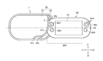
- FIG. 1 is a front view of a case according to one embodiment of the present invention.
- FIG. 2 is a front view showing a process where the electronic device is inserted into the case
- FIG. 3 is a font view showing the case with an electronic device stored therein;
- FIG. 4 is a cross sectional view of the case along the line IV-IV shown in FIG. 3 ;
- FIG. 5 is a bottom view showing the lower surface of the electronic device stored in the case.
- FIG. 1 is a front view of a case 1 according to one embodiment of the present invention.
- FIG. 2 is a front view showing a process where the electronic device 90 is inserted into the case 1 .
- FIG. 3 is a front view of the case 1 with the electronic device 90 stored therein.
- FIG. 4 is a cross sectional view of the case 1 along the line IV-IV shown in FIG. 3 .
- FIG. 5 is a bottom view showing the lower surface of the electronic device 90 stored in the case 1 .
- the directions X 1 and X 2 shown in FIG. 1 correspond to the left and right directions, respectively, and the directions Z 1 and Z 2 correspond to the up and down directions, respectively. Further, the directions Y 1 and Y 2 shown in FIG. 4 correspond to the forward and rearward directions, respectively.
- the electronic device 90 in this embodiment is a device having a shape of a substantially rectangular solid that is long in the left-right direction.
- the electronic device 90 has a display screen 91 on the front surface thereof.
- the electronic device 90 in this example functions as a game device, a motion image reproducing device, and a communication device, and thus includes, on the left and right of the display screen 91 , a plurality of operating members for user operation. Specifically, a plurality of operation buttons 92 A and an operating stick 92 B are arranged on the right of the display screen 91 .
- a directive key 92 C having a cross shape as a whole and an operating stick 92 D are arranged on the left of the display screen 91 .
- the operating members 92 A to 92 D project from the front surface of the electronic device 90 .
- the operating members 92 B, 92 D each include an a stem 92 a projecting from the front surface of the electronic device 90 (see FIG. 4 ) and further are adapted to inclination in the radius direction thereof, such as the up-down direction (Z 1 -Z 2 direction), the left-right direction (X 1 -X 2 direction) and so forth, and rotation along the circumferential direction while being inclined.
- the operating sticks 92 B, 92 D may be slidable in the radius direction of the stem 92 a .
- the height in projection of the operating sticks 92 B, 92 D is larger than that of the operation button 92 A and the directive key 92 C.
- the case 1 is a case for storing the electronic device 90 .
- the case 1 and the electronic device 90 may be together used as a single device when the electronic device 90 is stored in the case 1 .
- the case 1 includes a back cover 2 for covering the rear surface of the electronic device 90 and a front cover 20 for covering the front surface of the electronic device 90 .
- These two covers 2 , 20 are made of stretch sheet material.
- the cover 2 , 20 is made of rubber (e.g., chloroprene rubber) or the like that has flexibility and cushioning properties as well as strechability.
- the cover 2 , 20 has a shape in conformity with the electronic device 90 .
- the electronic device 90 in this example has a lateral surface 90 a that is curved into an arc shape (see FIG. 2 ), while the left and right edges of the case 1 are also curved into an arc shape.
- the case 1 has a size in conformity with the electronic device 90 .
- the size of the cover 2 is slightly smaller than that of the electronic device 90 in a front view of the cover 1 . Accordingly, the cover 2 , 20 is slightly stretched when the electronic device 90 is stored in the case 1 .
- the front cover 20 includes a side cover 22 and a main cover 21 .
- the side cover 22 can cover the front surface on a right side part (a first part in claims) of the electronic device 90 where the operating stick 92 B is arranged.
- the main cover 21 covers the front surface of the remaining part (a second part in claims) of the electronic device 90 , that is, the front surface on a left side part of the electronic device 90 and the display screen 91 . Accordingly, the main cover 21 has a larger left-right width than that of the side cover 22 .
- the main cover 21 together with the back cover 2 , forms a pocket A in which the remaining part of the electronic device 90 , that is, a part other than the right side part of the electronic device 90 , can be stored (the remaining part of the electronic device 90 being hereinafter referred to as a pocket-storing part 90 A (see FIG. 2 )).
- the side cover 22 together with the back cover 2 , forms a flap B in which the right side part of the electronic device 90 can be stored.
- the electronic device 90 can be inserted into, and removed from, the pocket A through between the main cover 21 and the side cover 22 .
- the side cover 22 is folded backward relative to the main cover 21 to thereby widen the space between the side cover 22 and the main cover to have the inlet of the pocket A appear. Then, the pocket-storing part 90 A of the electronic device 90 is inserted into the pocket A from the inlet. Then, while utilizing the strechability of the side cover 22 , the side cover 22 is brought to cover the right side part of the electronic device 90 . Meanwhile, in removing the electronic device 90 , while utilizing the strechability of the side cover 22 , the side cover 22 is folded backward with respect to the main cover 21 so that the right side part of the electronic device 90 is exposed out of the flap B. Then, the electronic device 90 is removed from the pocket A.
- the main cover 21 includes a pocket rim 21 a that functions as a rim of the opening of the pocket A.
- the side cover 22 includes a flap rim 22 a which overlaps the main cover 21 . That is, the flap rim 22 a is positioned on the front side of the main cover 21 . As the flap rim 22 a overlaps the main cover 21 , the entire front surface of the electronic device 90 can be covered. Further, as a space is widely opened between the pocket rim 21 a and the flap rim 22 a , it is possible to insert or remove the electronic device 90 with respect to the pocket A, as described above.
- a rim of the main cover 21 other than the pocket rim 21 a is connected to the outer rim of the back cover 2
- a rim of the side cover 22 other than the flap rim 22 a is connected to the outer rim of the back cover 2
- the main cover 21 , the side cover 22 , and the back cover 2 are separate sheet members before manufacturing the case 1
- the rim of the main cover 21 and that of the side cover 22 are sewn onto the outer rim of the back cover 2
- the rims of the covers 2 , 21 , 22 in this example are bordered by a bias tape 3 .
- a thread 3 a for sewing the bias tape 3 is shown in FIG. 1 .
- one end (the upper end in this example) 22 b of the a pocket rim 22 a is positioned further away from the center line C 1 defining a center of the case 1 in the insertion/removal direction (the left-right direction in this example) of the electronic device 90 with respect to the pocket A, compared with the other end 22 c (the lower end in this example) (the insertion/removal direction being hereinafter simply referred to as a left-right direction).
- a width by which the side cover 22 covers the electronic device 90 that is, the width W 1 in the left-right direction, is shorter in the upper part of the side cover 22 .
- the center line C 1 is defined as a straight line passing through the center of the case 1 in the insertion/removal direction of the electronic device 90 and being parallel to a flat surface including the case 1 .
- the flap rim 22 a in this example is formed substantially linear and diagonal relative to the left-right direction. Accordingly, the distance D 1 between the flap rim 22 a and a straight line L 1 that extends along a right end of the case 1 and is parallel to the center line C 1 becomes gradually shorter as it goes upward. With the linear shape of the flap rim 22 a , the flap rim 22 a can become taut when the electronic device 90 is stored. As a result, the linear flap rim 22 a can be prevented from being opened when the electronic device 90 is stored.
- the outer circumferential rim of the case 1 in this example is shaped in conformity with the shape of the electronic device 90 , specifically comprising a linear part 1 a extending linear in the longitudinal direction (the left-right direction) of the electronic device 90 and a curved part 1 b extending downward from the linear part 1 a while being curved.
- the upper end 22 b of the flap rim 22 a is positioned at the boundary between the linear part 1 a and the curved part 1 b .
- This arrangement facilitates a work of covering the right side part of the electronic device 90 with the side cover 22 and exposing the right side part of the electronic device 90 out of the side cover 22 , compared to a shape with the upper end 22 b positioned on the linear part 1 a.
- the electronic device 90 in this example has the lateral surface 90 a that is curved as described above. Such a shape of the electronic device 90 facilitates a work of covering the right side part of the electronic device 90 with the side cover 22 and removing the side cover 22 from the right side part of the electronic device 90 . Further, the rear surface of the electronic device 90 in this example is curved in its outer circumferential part 90 c , as shown in FIG. 4 . Such a shape of the rear surface further facilitates a work of covering the right side part of the electronic device 90 with the side cover 22 .
- the pocket rim 21 a of the main cover 21 is hidden under the side cover 22 .
- One end (an end overlapped by the one end 22 b of the flap rim 22 a ) of the pocket rim 21 a is positioned further away from the center line C 1 of the case 1 compared with the other end of the pocket rim 21 a .
- the operating stick 92 B of the electronic device 90 in this example is arranged in a position lower than the center line C 2 in the up-down direction of the electronic device 90 .
- the lower end 21 c of the pocket rim 21 a is positioned closer to the center line C 1 than the upper end 21 b is so that the main cover 21 avoid the operating stick 92 B.
- the upper end 21 b of the pocket rim 21 a is positioned further away from the center line C 1 of the case 1 than the lower end 21 c is. Further, the pocket rim 21 a get closer to the center line C 1 of the case 1 as it goes from the upper end 21 b to the lower end 21 c . Moreover, the upper end 22 b of the flap rim 22 a as well is positioned further away from the center line C 1 than the lower end 22 c is, as described above.
- the above described shapes of the flap rim 22 a and the pocket rim 21 a can readily lead to a design of the case 1 that ensure the pocket rim 21 a does not abut on the operating stick 92 B, while facilitating insertion/removal work of the electronic device 90 and protecting the front surface of the electronic device 90 (see FIG. 3 ).
- the width W 1 (see FIG. 1 ) in the left-right direction is shorter in the upper part of the side cover 22 , insertion/removal work of the electronic device 90 can be facilitated.
- the pocket rim 21 a get closer to the center line C 1 of the case 1 toward the lower end 21 c , designing to have the pocket rim 21 a avoid the operating stick 92 B can become easier.
- the side cover 22 and the main cover 21 can cover all area in the front surface of the electronic device 90 though the width in the left-right direction of the main cover 21 is shorter in its lower part.
- the upper end 22 b of the flap rim 22 a is positioned closer to the center line C 1 of the case 1 than the upper end 21 b of the pocket rim 21 a is. That is, the side cover 22 overlaps the upper end 21 b of the pocket rim 21 a . This makes it easier to surely prevent exposure of the front surface of the electronic device 90 .
- the pocket rim 21 a includes a curved part 21 d on a lower part thereof that is curved toward the center line C 1 of the case 1 .
- a shape of the pocket rim 21 a can further readily lead to a design of the case 1 that ensures the pocket rim 21 a does not abut on the operating stick 92 B.
- curving the pocket rim 21 a in the curved part 21 d allows the pocket rim 21 a to include an extending part 21 f , to be described later, that extends in the left-right direction.
- the curved part 21 d of the pocket rim 21 a is positioned closer to the center line C 1 of the case 1 than the operating stick 92 B is. This can prevent the operating stick 92 B from being inclined rightward by the pocket rim 21 a .
- the electronic device 90 also has the operating stick 92 D, as described above, positioned to the left of the display screen 91 .
- the operating stick 92 D is covered by the main cover 21 . In such a condition, the majority of a force applied to the operating stick 92 D by the main cover 21 is to press the operating stick 92 D toward the electronic device 90 , and thus a force for inclining the operating stick 92 D is limited.
- the side cover 22 has an overlap width W 2 by which the side cover 22 overlaps the main cover 21 .
- the overlap width in the middle part (that is, the middle in the up-down direction) of the flap rim 22 a is larger than that on the upper end 22 b of the flap rim 22 a .
- This arrangement of the side cover 22 and the main cover 21 makes it easier to prevent the overlap width W 2 from disappearing even when the electronic device 90 is stored.
- the side cover 22 is stretched due to the thickness of the electronic device 90 , and accordingly, the middle part of the flap rim 22 a moves relatively in the right direction relative to the pocket rim 21 a . As a result, the overlap width W 2 is reduced (see FIG.
- the flap rim 22 a and the pocket rim 21 a are formed such that the overlap width W 2 therebetween becomes gradually larger as it goes from the upper end 22 b , 21 b toward the lower end 22 c , 21 c .
- the overlap width W 2 keeps increasing as it goes from the upper end 22 b , 21 b to an area lower than the center line C 2 in the up-down direction.
- the flap rim 22 a is formed more sharply diagonal relative to the direction along the center line C 1 , that is, the up-down direction, than the pocket rim 21 a is.
- a gap G 1 in the left-right direction is defined between the lower end 21 c of the pocket rim 21 a and the lower end 22 c of the flap rim 22 a . That is, the lower end 21 c of the pocket rim 21 a is positioned closer to the center line C 1 of the case 1 than the lower end 22 c of the flap rim 22 a is.
- the gap G 1 constitutes an opening E enclosed by the flap rim 22 a , the pocket rim 21 a , and the rim of the back cover 2 .
- the opening E is directed downward when the electronic device 90 is stored, as shown in FIG. 5 , so that the lower surface of the electronic device 90 can be partially exposed through the opening E.
- a connector 95 is formed on the lower surface of the electronic device 90 .
- the connector 95 can be exposed through the opening E.
- the connector 95 is, e.g., a headphone jack, but alternatively, may be a charge connector of the electronic device 90 .
- the pocket rim 21 a has the curved part 21 d .
- the pocket rim 21 a is curved in the curved part 21 d toward the center line C 1 of the case 1 , and thereafter extends in the left-right direction toward the center line C 1 . That is, the pocket rim 21 a has an extending part 21 f that extends in the left-right direction between an end of the curved part 21 d and the lower end 21 c .
- the extending part 21 f makes it easier to sufficiently ensure a width of the opening E in the left-right direction, that is, the gap G 1 . Accordingly, the connector 95 can be reliably exposed even if the electronic device 90 should move in the case 1 .
- the overlap width W 2 between the side cover 22 and the main cover 21 becomes smaller at the time when the electronic device 90 is stored than the time when the electronic device 90 is not stored.
- the extending part 21 f to the pocket rim 21 a can prevent exposure of a lower side of the front surface of the electronic device 90 due to reduction of the overlap width W 2 .
- the curved part 21 d is designed to end in a position on the lower edge of the electronic device 90 stored.
- the gap G 2 between the outer rim of the back cover 2 and the extending part 21 f is designed to be positioned along the lower edge of the electronic device 90 stored (see FIG. 3 ). Therefore, the opening E is not seen in the front view of the case 1 when the electronic device 90 is stored, as shown in FIG. 3 . Consequently, this makes it possible to protect the entire front surface of the electronic device 90 , while keeping the connector 95 exposed downward.
- the electronic device 90 is inserted into the pocket A through between the side cover 22 and the main cover 21 , and the right side part of the electronic device 90 is covered by the flap B, the electronic device 90 can be prevented from being exposed out of the case 1 when not desired. Further, because the upper end 22 b of the flap rim 22 a is positioned further away from the center line C 1 of the case 1 than the lower end 22 c is, insertion and removal of the electronic device 90 can be easily performed, compared to a structure in which the two ends 22 b , 22 c are positioned equidistant from the center line C 1 .
- the pocket rim 21 a gets closer to the center line C 1 of the case 1 as it goes from the upper end 21 b to the lower end 21 c , and this arrangement readily leads to a design that ensures the pocket rim 21 a does not abut on the operating stick 92 B.
- the upper end 22 b of the flap rim 22 a is positioned closer to the center line C 1 of the case 1 than the upper end 21 b of the pocket rim 21 a . This arrangement makes it easier to prevent exposure of the front surface of the electronic device 90 .
- the overlap width W 2 between the side cover 22 and the main cover 21 is larger in the middle part of the rim 21 a , 22 a than on the upper end 22 b , 21 b . This arrangement of the side cover 22 and the main cover 21 makes it less likely that the front surface of the electronic device 90 stored is exposed.
- the pocket rim 21 a includes has the curved part 21 d that is curved toward the center line C 1 of the case 1 and positioned toward the lower end 21 c . This shape can further readily lead to a design that ensures the pocket rim 21 a does not abut on the operating stick 92 B.
- the gap G 1 is ensured between the lower end 21 c of the pocket rim 21 a and the lower end 22 c of the flap rim 22 a .
- This structure allows a component formed on the lower side of the electronic device 90 and usable when the electronic device 90 is stored to be exposed outside. Specifically, in the above description, the connector 95 formed on the lower surface of the electronic device 90 can be exposed. While the gap G 1 is ensured between the lower end 21 c of the pocket rim 21 a and the lower end 22 c of the flap rim 22 a , the upper end 22 b of the flap rim 22 a is positioned closer to the center line C 1 of the case 1 than the upper end 21 b of the pocket rim 21 a is. This can prevent unnecessary exposure.
- the pocket rim 21 a is curved in the curved part 21 d toward the center line C 1 of the case 1 , and thereafter extends toward the center line C 1 in the left-right direction. This structure makes it easier to sufficiently ensure a width of the opening E through which to expose the connecter 95 .
- the pocket rim 21 a is positioned closer to the center line C 1 of the case 1 than the operating stick 92 B is, when the electronic device 90 is stored. This can prevent the pocket rim 21 a from pressing the operating stick 92 B.
- the flap rim 22 a is formed linear in the above description, the middle of the flap rim 22 a may be curved, e.g., toward the main cover 21 .
- main cover 21 is sewed onto the back cover 2
- side cover 22 as well is sewed onto the back cover 2
- the main cover 21 and the back cover 2 may be integrally made using a single sheet of material.
- the side cover 22 and the back cover 2 may be integrally made, using a single sheet of material.
- this gap G 1 is ensured between the lower end 22 c of the flap rim 22 a and the lower end 21 c of the pocket rim 21 a in the above description, this gap G 1 may not be necessarily provided.
Abstract
Description
Claims (10)
Applications Claiming Priority (2)
| Application Number | Priority Date | Filing Date | Title |
|---|---|---|---|
| JP2011126790A JP4955826B1 (en) | 2011-06-06 | 2011-06-06 | Case for portable electronic devices |
| JP2011-126790 | 2011-06-06 |
Publications (2)
| Publication Number | Publication Date |
|---|---|
| US20120305423A1 US20120305423A1 (en) | 2012-12-06 |
| US8607975B2 true US8607975B2 (en) | 2013-12-17 |
Family
ID=44862282
Family Applications (1)
| Application Number | Title | Priority Date | Filing Date |
|---|---|---|---|
| US13/251,649 Active 2032-02-27 US8607975B2 (en) | 2011-06-06 | 2011-10-03 | Case for portable electronic device |
Country Status (4)
| Country | Link |
|---|---|
| US (1) | US8607975B2 (en) |
| EP (1) | EP2532264A3 (en) |
| JP (1) | JP4955826B1 (en) |
| CN (1) | CN202396675U (en) |
Cited By (3)
| Publication number | Priority date | Publication date | Assignee | Title |
|---|---|---|---|---|
| USD984450S1 (en) * | 2020-09-22 | 2023-04-25 | Korrun International Pte. Ltd. | Reversible sleeve |
| USD987646S1 (en) * | 2021-08-10 | 2023-05-30 | Weiping Huang | Laptop sleeve |
| USD1023010S1 (en) * | 2020-04-28 | 2024-04-16 | Acer Incorporated | Notebook computer storage combination including an accessory bag, a cover and a sleeve |
Citations (13)
| Publication number | Priority date | Publication date | Assignee | Title |
|---|---|---|---|---|
| USD302698S (en) * | 1986-04-21 | 1989-08-08 | The Mead Corporation | Portfolio |
| USD467079S1 (en) * | 2001-08-22 | 2002-12-17 | Keith Willows | Utility pouch |
| USD532199S1 (en) * | 2005-05-31 | 2006-11-21 | Nite Ize Inc. | Carrier pouch |
| US20070202956A1 (en) | 2003-09-26 | 2007-08-30 | Shinichi Ogasawara | Portable Electronic Device |
| USD588359S1 (en) * | 2006-07-28 | 2009-03-17 | J. Choo Limited | Handbag |
| USD592400S1 (en) * | 2007-11-01 | 2009-05-19 | Thule Organization Solutions, Inc. | Stretchable notebook computer case |
| USD594659S1 (en) * | 2008-10-06 | 2009-06-23 | Built Ny, Inc. | Laptop sleeve |
| USD598650S1 (en) * | 2008-05-01 | 2009-08-25 | Built Ny, Inc. | Camera case |
| USD599546S1 (en) * | 2008-02-11 | 2009-09-08 | Built Ny, Inc. | Camera case |
| USD621617S1 (en) * | 2010-01-28 | 2010-08-17 | PC Treasures, Inc. | Stretchable computer carrying sleeve |
| USD624318S1 (en) * | 2009-11-02 | 2010-09-28 | Union Rich Usa Llc | Laptop sleeve |
| USD630246S1 (en) * | 2009-12-07 | 2011-01-04 | Cheryl Veronica Franklin | Spineless, reversible, fully encasing book cover |
| USD652624S1 (en) * | 2010-12-23 | 2012-01-24 | Gone Studio LLC | Computer sleeve |
Family Cites Families (1)
| Publication number | Priority date | Publication date | Assignee | Title |
|---|---|---|---|---|
| US20090114557A1 (en) * | 2007-11-01 | 2009-05-07 | Thule Organization Solutions, Inc. Dba Case Logic, Inc. | Stretchable Notebook Computer Case |
-
2011
- 2011-06-06 JP JP2011126790A patent/JP4955826B1/en active Active
- 2011-09-30 CN CN2011204366108U patent/CN202396675U/en not_active Expired - Lifetime
- 2011-10-03 US US13/251,649 patent/US8607975B2/en active Active
- 2011-10-06 EP EP11008095.9A patent/EP2532264A3/en not_active Withdrawn
Patent Citations (13)
| Publication number | Priority date | Publication date | Assignee | Title |
|---|---|---|---|---|
| USD302698S (en) * | 1986-04-21 | 1989-08-08 | The Mead Corporation | Portfolio |
| USD467079S1 (en) * | 2001-08-22 | 2002-12-17 | Keith Willows | Utility pouch |
| US20070202956A1 (en) | 2003-09-26 | 2007-08-30 | Shinichi Ogasawara | Portable Electronic Device |
| USD532199S1 (en) * | 2005-05-31 | 2006-11-21 | Nite Ize Inc. | Carrier pouch |
| USD588359S1 (en) * | 2006-07-28 | 2009-03-17 | J. Choo Limited | Handbag |
| USD592400S1 (en) * | 2007-11-01 | 2009-05-19 | Thule Organization Solutions, Inc. | Stretchable notebook computer case |
| USD599546S1 (en) * | 2008-02-11 | 2009-09-08 | Built Ny, Inc. | Camera case |
| USD598650S1 (en) * | 2008-05-01 | 2009-08-25 | Built Ny, Inc. | Camera case |
| USD594659S1 (en) * | 2008-10-06 | 2009-06-23 | Built Ny, Inc. | Laptop sleeve |
| USD624318S1 (en) * | 2009-11-02 | 2010-09-28 | Union Rich Usa Llc | Laptop sleeve |
| USD630246S1 (en) * | 2009-12-07 | 2011-01-04 | Cheryl Veronica Franklin | Spineless, reversible, fully encasing book cover |
| USD621617S1 (en) * | 2010-01-28 | 2010-08-17 | PC Treasures, Inc. | Stretchable computer carrying sleeve |
| USD652624S1 (en) * | 2010-12-23 | 2012-01-24 | Gone Studio LLC | Computer sleeve |
Cited By (3)
| Publication number | Priority date | Publication date | Assignee | Title |
|---|---|---|---|---|
| USD1023010S1 (en) * | 2020-04-28 | 2024-04-16 | Acer Incorporated | Notebook computer storage combination including an accessory bag, a cover and a sleeve |
| USD984450S1 (en) * | 2020-09-22 | 2023-04-25 | Korrun International Pte. Ltd. | Reversible sleeve |
| USD987646S1 (en) * | 2021-08-10 | 2023-05-30 | Weiping Huang | Laptop sleeve |
Also Published As
| Publication number | Publication date |
|---|---|
| JP4955826B1 (en) | 2012-06-20 |
| CN202396675U (en) | 2012-08-29 |
| EP2532264A3 (en) | 2017-01-18 |
| US20120305423A1 (en) | 2012-12-06 |
| EP2532264A2 (en) | 2012-12-12 |
| JP2012253290A (en) | 2012-12-20 |
Similar Documents
| Publication | Publication Date | Title |
|---|---|---|
| US20080302687A1 (en) | Case for electrical device and method of using same | |
| EP1956721B1 (en) | Case for electrical device and method of using same | |
| US8607975B2 (en) | Case for portable electronic device | |
| US8879245B2 (en) | Protective case for portable electronic device | |
| US9066442B2 (en) | Stand for electronic apparatus | |
| US6352322B1 (en) | Portable liquid crystal display device | |
| US7819702B2 (en) | Electronic apparatus and connector | |
| KR20140101295A (en) | Flexible terminal device | |
| US9749001B2 (en) | Enhanced shell geometry for a flexible case for a portable electronic device | |
| US7855875B2 (en) | Image display device and electronic apparatus | |
| JP3672249B2 (en) | Computer device, keyboard, keyboard unit, bezel | |
| US20080259539A1 (en) | Electronic apparatus | |
| US20170280572A1 (en) | Electronic device | |
| US9182787B2 (en) | Removable cover panel for display housing | |
| JP2012253323A (en) | Portable electronic apparatus case | |
| US11600900B2 (en) | Electronic device | |
| US20120247983A1 (en) | Tablet bay and bag incorporating the same | |
| US20080259565A1 (en) | Heat radiator and electronic apparatus | |
| KR101844398B1 (en) | Neckband headset with folderable hinge device | |
| JP3109489U (en) | Portable electronic device case | |
| JP7078781B1 (en) | Electronic device covers and toys | |
| JP2013038134A (en) | Electronic apparatus | |
| CN106926203A (en) | The cover of electric tool and electric tool | |
| JP6201091B1 (en) | Cover for holding mobile device | |
| JP3393960B2 (en) | Image forming device |
Legal Events
| Date | Code | Title | Description |
|---|---|---|---|
| AS | Assignment |
Owner name: SONY COMPUTER ENTERTAINMENT INC., JAPAN Free format text: ASSIGNMENT OF ASSIGNORS INTEREST;ASSIGNORS:TAI, HITOMI;HIRAYAMA, YUKO;SIGNING DATES FROM 20111011 TO 20111012;REEL/FRAME:027086/0580 |
|
| AS | Assignment |
Owner name: SONY CORPORATION, JAPAN Free format text: ASSIGNMENT OF ASSIGNORS INTEREST;ASSIGNOR:SONY COMPUTER ENTERTAINMENT INC.;REEL/FRAME:031329/0072 Effective date: 20130926 |
|
| FEPP | Fee payment procedure |
Free format text: PAYOR NUMBER ASSIGNED (ORIGINAL EVENT CODE: ASPN); ENTITY STATUS OF PATENT OWNER: LARGE ENTITY |
|
| STCF | Information on status: patent grant |
Free format text: PATENTED CASE |
|
| FPAY | Fee payment |
Year of fee payment: 4 |
|
| AS | Assignment |
Owner name: SONY INTERACTIVE ENTERTAINMENT INC., JAPAN Free format text: CHANGE OF NAME;ASSIGNOR:SONY COMPUTER ENTERTAINMENT INC.;REEL/FRAME:043761/0577 Effective date: 20160401 Owner name: SONY INTERACTIVE ENTERTAINMENT INC., JAPAN Free format text: ASSIGNMENT OF ASSIGNORS INTEREST;ASSIGNOR:SONY CORPORATION;REEL/FRAME:043761/0975 Effective date: 20170825 |
|
| MAFP | Maintenance fee payment |
Free format text: PAYMENT OF MAINTENANCE FEE, 8TH YEAR, LARGE ENTITY (ORIGINAL EVENT CODE: M1552); ENTITY STATUS OF PATENT OWNER: LARGE ENTITY Year of fee payment: 8 |