US8551002B2 - Spatial array of sensors mounted on a tool - Google Patents

Spatial array of sensors mounted on a tool Download PDF

Info

Publication number
US8551002B2
US8551002B2 US12/333,600 US33360008A US8551002B2 US 8551002 B2 US8551002 B2 US 8551002B2 US 33360008 A US33360008 A US 33360008A US 8551002 B2 US8551002 B2 US 8551002B2
Authority
US
United States
Prior art keywords
tool
sensors
patient
array
blood
Prior art date
Legal status (The legal status is an assumption and is not a legal conclusion. Google has not performed a legal analysis and makes no representation as to the accuracy of the status listed.)
Expired - Fee Related, expires
Application number
US12/333,600
Other versions
US20100152586A1 (en
Inventor
Danny A. Grant
Juan Manuel Cruz-Hernandez
Christopher J. Ullrich
Current Assignee (The listed assignees may be inaccurate. Google has not performed a legal analysis and makes no representation or warranty as to the accuracy of the list.)
Immersion Corp
Original Assignee
Immersion Corp
Priority date (The priority date is an assumption and is not a legal conclusion. Google has not performed a legal analysis and makes no representation as to the accuracy of the date listed.)
Filing date
Publication date
Application filed by Immersion Corp filed Critical Immersion Corp
Priority to US12/333,600 priority Critical patent/US8551002B2/en
Assigned to IMMERSION CORPORATION reassignment IMMERSION CORPORATION ASSIGNMENT OF ASSIGNORS INTEREST (SEE DOCUMENT FOR DETAILS). Assignors: ULLRICH, CHRISTOPHER J., CRUZ-HERNANDEZ, JUAN MANUEL, GRANT, DANNY A.
Priority to PCT/US2009/066908 priority patent/WO2010068572A1/en
Priority to JP2011540791A priority patent/JP5683482B2/en
Priority to EP09765212.7A priority patent/EP2355709B1/en
Publication of US20100152586A1 publication Critical patent/US20100152586A1/en
Application granted granted Critical
Publication of US8551002B2 publication Critical patent/US8551002B2/en
Expired - Fee Related legal-status Critical Current
Adjusted expiration legal-status Critical

Links

Images

Classifications

    • AHUMAN NECESSITIES
    • A61MEDICAL OR VETERINARY SCIENCE; HYGIENE
    • A61BDIAGNOSIS; SURGERY; IDENTIFICATION
    • A61B17/00Surgical instruments, devices or methods, e.g. tourniquets
    • A61B17/28Surgical forceps
    • A61B17/29Forceps for use in minimally invasive surgery
    • AHUMAN NECESSITIES
    • A61MEDICAL OR VETERINARY SCIENCE; HYGIENE
    • A61BDIAGNOSIS; SURGERY; IDENTIFICATION
    • A61B34/00Computer-aided surgery; Manipulators or robots specially adapted for use in surgery
    • A61B34/70Manipulators specially adapted for use in surgery
    • A61B34/76Manipulators having means for providing feel, e.g. force or tactile feedback
    • AHUMAN NECESSITIES
    • A61MEDICAL OR VETERINARY SCIENCE; HYGIENE
    • A61BDIAGNOSIS; SURGERY; IDENTIFICATION
    • A61B5/00Measuring for diagnostic purposes; Identification of persons
    • A61B5/103Detecting, measuring or recording devices for testing the shape, pattern, colour, size or movement of the body or parts thereof, for diagnostic purposes
    • AHUMAN NECESSITIES
    • A61MEDICAL OR VETERINARY SCIENCE; HYGIENE
    • A61BDIAGNOSIS; SURGERY; IDENTIFICATION
    • A61B5/00Measuring for diagnostic purposes; Identification of persons
    • A61B5/48Other medical applications
    • A61B5/4887Locating particular structures in or on the body
    • A61B5/489Blood vessels
    • AHUMAN NECESSITIES
    • A61MEDICAL OR VETERINARY SCIENCE; HYGIENE
    • A61BDIAGNOSIS; SURGERY; IDENTIFICATION
    • A61B8/00Diagnosis using ultrasonic, sonic or infrasonic waves
    • A61B8/08Detecting organic movements or changes, e.g. tumours, cysts, swellings
    • AHUMAN NECESSITIES
    • A61MEDICAL OR VETERINARY SCIENCE; HYGIENE
    • A61BDIAGNOSIS; SURGERY; IDENTIFICATION
    • A61B8/00Diagnosis using ultrasonic, sonic or infrasonic waves
    • A61B8/44Constructional features of the ultrasonic, sonic or infrasonic diagnostic device
    • A61B8/4483Constructional features of the ultrasonic, sonic or infrasonic diagnostic device characterised by features of the ultrasound transducer
    • AHUMAN NECESSITIES
    • A61MEDICAL OR VETERINARY SCIENCE; HYGIENE
    • A61BDIAGNOSIS; SURGERY; IDENTIFICATION
    • A61B17/00Surgical instruments, devices or methods, e.g. tourniquets
    • A61B17/00234Surgical instruments, devices or methods, e.g. tourniquets for minimally invasive surgery
    • AHUMAN NECESSITIES
    • A61MEDICAL OR VETERINARY SCIENCE; HYGIENE
    • A61BDIAGNOSIS; SURGERY; IDENTIFICATION
    • A61B17/00Surgical instruments, devices or methods, e.g. tourniquets
    • A61B2017/00017Electrical control of surgical instruments
    • A61B2017/00022Sensing or detecting at the treatment site
    • AHUMAN NECESSITIES
    • A61MEDICAL OR VETERINARY SCIENCE; HYGIENE
    • A61BDIAGNOSIS; SURGERY; IDENTIFICATION
    • A61B17/00Surgical instruments, devices or methods, e.g. tourniquets
    • A61B2017/00743Type of operation; Specification of treatment sites
    • A61B2017/00778Operations on blood vessels
    • AHUMAN NECESSITIES
    • A61MEDICAL OR VETERINARY SCIENCE; HYGIENE
    • A61BDIAGNOSIS; SURGERY; IDENTIFICATION
    • A61B90/00Instruments, implements or accessories specially adapted for surgery or diagnosis and not covered by any of the groups A61B1/00 - A61B50/00, e.g. for luxation treatment or for protecting wound edges
    • A61B90/06Measuring instruments not otherwise provided for
    • A61B2090/064Measuring instruments not otherwise provided for for measuring force, pressure or mechanical tension
    • A61B2090/065Measuring instruments not otherwise provided for for measuring force, pressure or mechanical tension for measuring contact or contact pressure
    • AHUMAN NECESSITIES
    • A61MEDICAL OR VETERINARY SCIENCE; HYGIENE
    • A61BDIAGNOSIS; SURGERY; IDENTIFICATION
    • A61B90/00Instruments, implements or accessories specially adapted for surgery or diagnosis and not covered by any of the groups A61B1/00 - A61B50/00, e.g. for luxation treatment or for protecting wound edges
    • A61B90/36Image-producing devices or illumination devices not otherwise provided for
    • A61B90/37Surgical systems with images on a monitor during operation
    • A61B2090/378Surgical systems with images on a monitor during operation using ultrasound
    • A61B2090/3782Surgical systems with images on a monitor during operation using ultrasound transmitter or receiver in catheter or minimal invasive instrument
    • A61B2090/3784Surgical systems with images on a monitor during operation using ultrasound transmitter or receiver in catheter or minimal invasive instrument both receiver and transmitter being in the instrument or receiver being also transmitter
    • AHUMAN NECESSITIES
    • A61MEDICAL OR VETERINARY SCIENCE; HYGIENE
    • A61BDIAGNOSIS; SURGERY; IDENTIFICATION
    • A61B2562/00Details of sensors; Constructional details of sensor housings or probes; Accessories for sensors
    • A61B2562/02Details of sensors specially adapted for in-vivo measurements
    • A61B2562/0247Pressure sensors
    • AHUMAN NECESSITIES
    • A61MEDICAL OR VETERINARY SCIENCE; HYGIENE
    • A61BDIAGNOSIS; SURGERY; IDENTIFICATION
    • A61B2562/00Details of sensors; Constructional details of sensor housings or probes; Accessories for sensors
    • A61B2562/04Arrangements of multiple sensors of the same type
    • A61B2562/046Arrangements of multiple sensors of the same type in a matrix array
    • AHUMAN NECESSITIES
    • A61MEDICAL OR VETERINARY SCIENCE; HYGIENE
    • A61BDIAGNOSIS; SURGERY; IDENTIFICATION
    • A61B5/00Measuring for diagnostic purposes; Identification of persons
    • A61B5/02Detecting, measuring or recording pulse, heart rate, blood pressure or blood flow; Combined pulse/heart-rate/blood pressure determination; Evaluating a cardiovascular condition not otherwise provided for, e.g. using combinations of techniques provided for in this group with electrocardiography or electroauscultation; Heart catheters for measuring blood pressure
    • A61B5/024Detecting, measuring or recording pulse rate or heart rate

Definitions

  • the embodiments of the present disclosure generally relate to hand tools and more particularly relate to mounting an array of sensors on an end of a hand tool.
  • minimally invasive surgical procedures are performed by making relatively small incisions and then inserting tools through the incisions to access the organs.
  • Minimally invasive surgery usually results in shorter hospitalization times, reduced therapy requirements, less pain, less scarring, and fewer complications.
  • a surgeon can introduce a miniature camera through an incision.
  • the camera transmits images to a visual display, allowing the surgeon to see the internal organs and tissues and to see the effect of other minimally invasive tools on the organs and tissues.
  • the surgeon is able to perform laparoscopic surgery, dissection, cauterization, endoscopy, telesurgery, etc.
  • minimally invasive surgery can present limitations regarding the surgeon's ability to see and feel the patient's organs and tissues.
  • a tool is defined as having a handle configured to be manipulated by a user.
  • the tool includes an end portion arranged in mechanical communication with the handle.
  • An array of sensors is mounted on the end portion and is configured to sense a property of an object.
  • the tool also comprises a processing device configured to process the properties of the object sensed by the array of sensors and to obtain spatial information of the object.
  • the processing device is further configured to communicate the spatial information to the handle.
  • FIG. 1 is a diagram of a surgical hand tool having a sensor array, according to one embodiment.
  • FIG. 2 is a diagram of the sensor array shown in FIG. 1 , according to one embodiment.
  • FIG. 3 is a block diagram of a system for communicating sensed properties to a user, according to a first embodiment.
  • FIG. 4 is a block diagram of a system for communicating sensed properties to a user, according to a second embodiment.
  • FIG. 5 is a flow diagram illustrating a method for operating an array of sensors on a tool, according to one embodiment.
  • minimally invasive surgical procedures involving small incisions include many advantages over open surgery, minimally invasive surgery can still create challenges to a surgeon.
  • the surgeon must typically rely on a camera to view the patient's internal organs and see how the movement and operation of the tools affects the organs.
  • the surgeon is usually unable to palpate or receive tactile feedback with respect to the stiffness and/or pulsation of organs.
  • it can be beneficial to re-introduce the surgeon to the concept of palpation by providing tactile or haptic feedback in some manner in order to communicate better the sensation and feel of the patient's organs to the surgeon.
  • the present disclosure describes embodiments that include any type of tools that can be manipulated by a user. More particularly, the tools described in the present disclosure include a handle portion that mechanically controls an end portion of the tool. Mounted on the end portion is an array of sensors for sensing a property of an object that interacts with the tool. Using the information from the multiple sensors, additional properties of the object can be determined. For instance, the spatial relationship of the different sensors can be used to determine spatial information. Likewise, both spatial and temporal relationships of the sensed properties at the different sensors over time can also be used to determine specific information about the object.
  • FIG. 1 illustrates an embodiment of a surgical tool 10 .
  • surgical tool 10 is shown as a hand-held laparoscopic tool, which is configured to be inserted through a small incision in the abdomen of a patient.
  • Surgical tool 10 in this embodiment includes a handle 12 , a shaft 14 , and an end portion 16 .
  • Shaft 14 is designed to connect handle 12 to end portion 16 and to communicate mechanical actions of handle 12 to end portion 16 .
  • Shaft 14 is further designed to communicate electrical signals from end portion 16 back to handle 12 as explained in more detail below.
  • end portion 16 includes a tip 18 and a sensor array 20 formed on tip 18 . As shown, tip 18 is a grasper.
  • end portion 16 may include any suitable type of tip having any suitable functionality.
  • sensor array 20 may be connected a portion of end portion 16 other than tip 18 .
  • shaft may be about 20 cm to 30 cm in length and tip 18 may be about 10 mm to 15 mm in length.
  • a user can insert end portion 16 into the abdomen of the patient and control tip 18 of end portion 16 .
  • the surgeon can further manipulate handle 12 to control the location and orientation of tip 18 such that sensor array 20 is able to contact certain regions of the patient.
  • Sensor array 20 can measure or test any desired property or parameter of the patient, such as, for example, pulse.
  • tip 18 can be controlled to position sensor array 20 to accomplish certain contactless sensing.
  • FIG. 2 is a diagram illustrating an embodiment of sensor array 20 shown in FIG. 1 .
  • Sensor array 20 includes a number of sensors 22 connected to a substrate 24 , which is configured to hold sensors 22 in a pattern having a predetermined pitch between sensors 22 .
  • sensor array 20 includes seven rows and two columns of sensors 22 from the perspective of handle 12 ( FIG. 1 ). It should be understood, however, that sensor array 20 can be arranged to include any number of rows and columns.
  • sensors 22 may be arranged in a pattern that does not particularly resemble a rectangular array. For example, sensors 22 can be positioned is a staggered pattern, circular pattern, etc.
  • sensors 22 may include any suitable shape, e.g., rectangular, circular, elliptical, etc. According to the embodiment of FIG. 2 in which sensors 22 are square, sensors 22 may have widths and lengths of about 2 mm and may be separated by a distance of about 0.5 mm. In some embodiments, the size of sensors 22 may be smaller to allow a greater number of sensors to be positioned in sensor array 20 . The size and number of sensors 22 may depend, for example, on the ability to miniaturize the particular type of sensor while keeping the integrity and usefulness of the sensor. If miniaturization techniques are used, the array of sensors 22 may include dozens of rows and columns of sensors 22 . Sensors 22 may also be of any size and shape on substrate 24 .
  • Sensors 22 can be configured to sense any suitable property of the object under test.
  • sensors 22 can be configured as pressure sensors using resistive or capacitive pressure sensing technologies.
  • sensors 22 can include strain gauges, piezoelectric sensors, stiffness sensors, etc.
  • strain gauges sensors 22 can provide additional information about contact force to finely tune a generally course measurement of force.
  • piezoelectric sensors sensors 22 can generate ultrasound signals that reflect off portions of the object. In this case, echo signals can be detected by sensors 22 to determine the location of objects. The ultrasound emission and echo measurement technique may be particularly useful for sensing the location of luminal structures and for tumor tissue identification.
  • Sensors 22 can also be configured as stiffness sensors that can detect nodules, e.g., tumors, or other stiff regions.
  • the number of sensors 22 contacting the stiff region By processing the number of sensors 22 contacting the stiff region, a calculation can be made regarding the size of the nodules.
  • the number of sensors 22 that sense relative stiffness can be used to determine the size of the nodule and thereby increase or decrease an output signal provided to the user to communicate the size.
  • sensor array 20 can provide information indicative of the size of a particular feature, e.g., nodule, of the patient.
  • Substrate 24 may include any suitable structure for supporting sensors 22 on tip 18 ( FIG. 1 ). Depending on the size, shape, and rigidity of tip 18 , substrate 24 may be rigid or flexible to conform to tip 18 . Also, substrate 24 may be planar or curved depending on the structure of tip 18 . In the embodiment of FIG. 1 in which tip is a metal grasper with a curved bottom jaw, substrate 24 may be curved to conform to the curved shape of the bottom jaw. Also, since the jaw is substantially rigid, substrate 24 does not necessarily need to be rigid to provide needed support for sensors 22 and therefore can be flexible.
  • FIG. 3 is a block diagram illustrating an embodiment of a system 30 for communicating spatial information about an object to a user.
  • system 30 includes a sensor array 32 , processing device 34 , and output devices 36 .
  • system 30 contains sensor array 32 , processing device 34 , and output devices 36 on a hand-held tool or device.
  • sensor array 32 may be positioned on a portion of a tool, e.g., a tool used for probing an object.
  • Sensor array 32 is configured to include any type of sensing mechanisms to sense any suitable characteristic of the object.
  • the sensed information from each sensor is communicated to processing device 34 , which is configured to process the information according to specific algorithms.
  • processing device 34 can determine various characteristics of the object. Processing device 34 may then communicate the processed information to output device 36 , which is designed to present the information to the user in any suitable manner.
  • Sensor array 32 may represent any suitable sensor array positioned on an end of a tool for detecting one or more specific properties of an object.
  • sensor array 32 may be the same as or similar to sensor array 20 described with respect to FIGS. 1 and 2 .
  • sensor array 32 includes a plurality of sensors, each capable of measuring properties of an object at predefined locations with respect to the other sensors.
  • processing device 34 can determine or infer spatial information about the object. Processing device 34 may include different types of algorithms for extracting the particular information needed to calculate the spatial information.
  • a surgeon may use a tool having sensor array 32 positioned on the tool for measuring pulse.
  • processing device 34 may be configured to deduce that a blood vessel is positioned or oriented in that particular direction including that row of sensors where the pulse is detected.
  • pulse information is detected along a column or across a diagonal, then the position or orientation of a blood vessel can be inferred accordingly.
  • processing device 34 can also use any changes of the sensed information over time to extract temporal information.
  • the signals can be detected in real time to allow the processing of time-related signals.
  • processing device 34 may be able to detect peaks in the signals to determine when the signal is at its highest or lowest point.
  • processing device 34 can detect phase differences, etc.
  • processing device 34 may be configured to use the spatial and temporal information to detect not only the orientation of blood vessels, but also the direction in which the blood flows through the vessels. For example, pulse information can be detected at one instance of time and detected again along the path of the vessel at a later instance.
  • the sensors against which the blood vessel is in contact can sense the pulse.
  • the sensors adjacent to those sensors that are in contact with the vessel can experience a loss of contact with tissue due to the lifting action of the pulsing vessel on the contacted sensors.
  • the adjacent sensors may produce a signal that is 180 degrees out of phase with the pulse detecting sensors.
  • Processing device 34 can be configured to detect this phenomenon to determine the location of blood vessels and for detecting pulse information.
  • Processing device 34 may be a general-purpose or specific-purpose processor or microcontroller for processing the signals detected by sensor array 32 .
  • processing device 34 may include a plurality of processors for performing different functions with respect to system 30 .
  • processing device 34 may be associated with a memory device (not shown) for storing data and/or instructions.
  • the memory may include one or more internally fixed storage units, removable storage units, and/or remotely accessible storage units, and the various storage units may include any combination of volatile memory and non-volatile memory.
  • Logical instructions, commands, and/or code can be implemented in software, firmware, or both, and stored in memory. In this respect, the logic code may be implemented as one or more computer programs that can be executed by processing device 34 .
  • logical instructions, commands, and/or code can be implemented in hardware and incorporated in processing device 34 using discrete logic circuitry, an application specific integrated circuit (“ASIC”), a programmable gate array (“PGA”), a field programmable gate array (“FPGA”), etc., or any combination thereof.
  • ASIC application specific integrated circuit
  • PGA programmable gate array
  • FPGA field programmable gate array
  • logical instructions, commands, and/or code can be implemented in both hardware in processing device 34 and software/firmware stored in the memory.
  • Output devices 36 may include one or more mechanisms for communicating to a user information sensed by sensor array 32 and processed by processing device 34 .
  • Output devices 36 may include any suitable combination of display screens, speakers, tactile actuators, haptic effect devices, or other notification devices.
  • output devices 36 may include any number of feedback mechanisms in any number of modes for providing any type of visual, audible, and/or tactile output to the user.
  • output devices 36 may be used to provide feedback to the surgeon so that the surgeon can reposition the tool as necessary to align, orient, or position the tool to allow the sensing of a more reliable signal, to reduce pressure on particular organs, etc.
  • output devices 36 can include haptic actuators, which is able to generate a vibration on handle 12 .
  • the haptic actuators can include one or more force applying mechanisms that are configured to apply a vibrotactile force to a user of surgical tool 10 or other device.
  • the haptic actuators may include electromagnetic actuators, eccentric rotating mass (“ERM”) actuators in which an eccentric mass is moved by a motor, linear resonant actuator (“LRA”) in which a mass attached to a spring is driven back and forth, a “smart material” such as piezoelectric, electro-active polymers or shape memory alloys, or other suitable type of actuating device.
  • FIG. 4 illustrates a system block diagram for a computer-assisted hand tool in which palpation algorithms can be deployed in an exemplary embodiment.
  • the computer-assisted hand tool includes a plurality of sensors 40 , which could include accelerometers for detecting and measuring the acceleration of a tool, and a pressure sensor array for detecting pulses during movement of the tip of the tool on the tissue being palpated.
  • Processor 42 receives signals from sensors 40 and processes the received signals based on instructions stored in memory 44 , which may include, among other things, palpation algorithms 46 .
  • processor 42 can cause an actuator 48 of the tool to play a haptic effect.
  • haptic effect can refer to a tactile effect, tactile feedback, haptic feedback, force feedback, vibrotactile feedback, haptic cues, thermal feedback, kinesthetic feedback, etc.
  • haptic effect can include the representation of any physical properties (e.g., stiffness, viscosity, etc.).
  • the haptic effect played is characterized by one or more of the magnitude, frequency, and duration of the effect.
  • the haptic effect can be dynamic based on a changing level of stiffness or deformation of the tissue being examined.
  • processor 42 can be a laptop or personal computer that is electrically coupled to the tool.
  • the laptop or personal computer can have a graphical user interface (GUI) 50 that enables the user to select optional processing steps for the palpation algorithms.
  • GUI graphical user interface
  • Memory 44 can be any type of storage device or computer readable medium capable of storing the instructions for palpation algorithms 46 .
  • Memory 44 can include random access memory, read-only memory, etc.
  • processor 42 can be an application specific integrated circuit (ASIC) that is a component of the tool.
  • the instructions for palpation algorithms 46 can be embedded in processor 42 .
  • sensor array 40 can include a 2 ⁇ 7 array of pressure transducers. Each pressure transducer can be in contact with the tissue being palpated, therefore, each transducer is processed for pulses received. Each transducer can detect zero or more pulses in a predetermined time window.
  • Actuator 48 can generate a vibration on the handle of the tool. More specifically, the actuator 48 can include a force applying mechanism that applies a vibrotactile force to the tool based on a level of stiffness or deformation of the tissue being examined.
  • One parameter of the actuator that can be used in some embodiments is the peak voltage applied during the playing of haptic effects.
  • FIG. 5 is a flow diagram of an embodiment of a method of operating a tool having a sensor array.
  • a user is allowed to manipulate a tool according to a normal use of the tool.
  • the user may manipulate a handle, buttons, or other feature on the tool to control a functional portion of the tool.
  • the controlled portion may be a portion that is positioned on an opposite end from the handle. The controlled portion can be probed around to contact an object being tested or to be placed in proximity to the object being tested, depending on the particular type of parameter being measured.
  • a parameter of the object is sensed at multiple locations.
  • the multiple locations may represent the positioning of a number of sensors mounted on or relative to the tool, such as sensors that may be positioned on or near the controlled portion of the tool.
  • the sensing locations may form a predefined pattern, such as a rectangular array having rows and columns. In other embodiments, the sensing locations may include any other suitable pattern.
  • the sensed properties are processed to obtain spatial information about the object being tested. Based on the properties sensed at the multiple locations and based on a predetermined knowledge of the location and orientation of the sensors, spatial information can be obtained.
  • the sensed properties may be related to the blood of the patient. For example, if pulse information is detected at some sensor locations, the sensed information can be processed to determine the location and orientation of blood vessels of the patient.
  • the spatial information can also be obtained by processing the information at regular time intervals, allowing both spatial and temporal information to be obtained.
  • the spatiotemporal information can be used to determine not only the location and orientation of the blood vessels, but also the direction in which the blood flows through the blood vessels.
  • a signal may be strong at one sensor location at one time and, after a short delay, the signal may be strong at another sensor location, thereby indicating the flow direction.
  • the processing associated with block 46 is able to decode the sensed information from the multiple locations at multiple times to compute the spatial and/or spatiotemporal information.
  • an output is provided to the user to indicate the spatial information.
  • this information can also be output to the user.
  • the output may be presented in any suitable form.
  • the output may be a haptic or tactile effect imposed on the user.
  • the output may be haptic, audible, and/or visual. Any suitable combination of output mechanisms or actuators can be used to present the output.
  • haptic actuators can be arranged in an array or other pattern resembling the array or pattern of the sensors. In this case, the sensed signals can be mapped to provide a haptic effect to represent the spatial information sensed by the sensors.
  • routines, steps, processes, or operations described herein may represent any module or code sequence that can be implemented in software or firmware.
  • these modules and code sequences can include commands or instructions for executing the specific logical routines, steps, processes, or operations within physical components.
  • two or more of the routines, steps, processes, and/or operations described herein may be executed substantially simultaneously or in a different order than explicitly described, as would be understood by one of ordinary skill in the art.

Abstract

Systems and methods described herein include an array of sensors positioned on a tool. In one embodiment, among others, a tool includes a handle configured to be manipulated by a user. The tool also includes an end portion arranged in mechanical communication with the handle. In addition, the tool includes an array of sensors mounted on the end portion, in which the array of sensors is configured to sense a property of an object. The tool also comprises a processing device configured to process the properties of the object sensed by the array of sensors and to obtain spatial information of the object. The processing device is further configured to communicate the spatial information to the handle.

Description

TECHNICAL FIELD
The embodiments of the present disclosure generally relate to hand tools and more particularly relate to mounting an array of sensors on an end of a hand tool.
BACKGROUND
As opposed to open surgery in which a surgeon cuts a relatively large incision in the skin of a patient for accessing internal organs, minimally invasive surgical procedures are performed by making relatively small incisions and then inserting tools through the incisions to access the organs. Minimally invasive surgery usually results in shorter hospitalization times, reduced therapy requirements, less pain, less scarring, and fewer complications.
During minimally invasive surgery, a surgeon can introduce a miniature camera through an incision. The camera transmits images to a visual display, allowing the surgeon to see the internal organs and tissues and to see the effect of other minimally invasive tools on the organs and tissues. In this way, the surgeon is able to perform laparoscopic surgery, dissection, cauterization, endoscopy, telesurgery, etc. Compared to open surgery, however, minimally invasive surgery can present limitations regarding the surgeon's ability to see and feel the patient's organs and tissues.
SUMMARY
The present disclosure describes a number of embodiments in which an array of sensors is positioned on an end of a tool. Specifically, in one particular embodiment, a tool is defined as having a handle configured to be manipulated by a user. The tool includes an end portion arranged in mechanical communication with the handle. An array of sensors is mounted on the end portion and is configured to sense a property of an object. The tool also comprises a processing device configured to process the properties of the object sensed by the array of sensors and to obtain spatial information of the object. The processing device is further configured to communicate the spatial information to the handle.
The embodiments described in the present disclosure may include additional features and advantages, which may not necessarily be expressly disclosed herein but will be apparent to one of ordinary skill in the art upon examination of the following detailed description and accompanying drawings. It is intended that these additional features and advantages be included within the present disclosure.
BRIEF DESCRIPTION OF THE DRAWINGS
The components of the following figures are illustrated to emphasize the general principles of the present disclosure and are not necessarily drawn to scale. Reference characters designating corresponding components are repeated as necessary throughout the figures for the sake of consistency and clarity.
FIG. 1 is a diagram of a surgical hand tool having a sensor array, according to one embodiment.
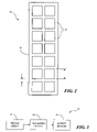
FIG. 2 is a diagram of the sensor array shown in FIG. 1, according to one embodiment.
FIG. 3 is a block diagram of a system for communicating sensed properties to a user, according to a first embodiment.
FIG. 4 is a block diagram of a system for communicating sensed properties to a user, according to a second embodiment.
FIG. 5 is a flow diagram illustrating a method for operating an array of sensors on a tool, according to one embodiment.
DETAILED DESCRIPTION
Although minimally invasive surgical procedures involving small incisions include many advantages over open surgery, minimally invasive surgery can still create challenges to a surgeon. For example, the surgeon must typically rely on a camera to view the patient's internal organs and see how the movement and operation of the tools affects the organs. Also, the surgeon is usually unable to palpate or receive tactile feedback with respect to the stiffness and/or pulsation of organs. To overcome the inherent limitation regarding touch, it can be beneficial to re-introduce the surgeon to the concept of palpation by providing tactile or haptic feedback in some manner in order to communicate better the sensation and feel of the patient's organs to the surgeon.
The present disclosure describes embodiments that include any type of tools that can be manipulated by a user. More particularly, the tools described in the present disclosure include a handle portion that mechanically controls an end portion of the tool. Mounted on the end portion is an array of sensors for sensing a property of an object that interacts with the tool. Using the information from the multiple sensors, additional properties of the object can be determined. For instance, the spatial relationship of the different sensors can be used to determine spatial information. Likewise, both spatial and temporal relationships of the sensed properties at the different sensors over time can also be used to determine specific information about the object.
Although many of the examples described in the embodiments of the present disclosure relate to surgical hand tools, such as minimally invasive surgical tools, it should be understood that the present disclosure also encompasses other types of tools as well. In addition, although many of examples herein relate to a surgical patients and how the organs and tissues of the patient interact with the surgical tools, it should also be understood that the present disclosure also includes other objects, which are normally intended to interact with the respective tools. Other features and advantages will be apparent to one of ordinary skill in the art upon reading and understanding the general principles of the present disclosure and are intended to be included herein.
FIG. 1 illustrates an embodiment of a surgical tool 10. In this diagram, surgical tool 10 is shown as a hand-held laparoscopic tool, which is configured to be inserted through a small incision in the abdomen of a patient. Surgical tool 10 in this embodiment includes a handle 12, a shaft 14, and an end portion 16. Shaft 14 is designed to connect handle 12 to end portion 16 and to communicate mechanical actions of handle 12 to end portion 16. Shaft 14 is further designed to communicate electrical signals from end portion 16 back to handle 12 as explained in more detail below. According to the embodiment of FIG. 1, end portion 16 includes a tip 18 and a sensor array 20 formed on tip 18. As shown, tip 18 is a grasper. However, it should be understood that end portion 16 may include any suitable type of tip having any suitable functionality. Also, in other alternative embodiments, sensor array 20 may be connected a portion of end portion 16 other than tip 18. According to some examples of the embodiment of FIG. 1, shaft may be about 20 cm to 30 cm in length and tip 18 may be about 10 mm to 15 mm in length.
By manipulating handle 12, a user can insert end portion 16 into the abdomen of the patient and control tip 18 of end portion 16. When end portion 16 is inserted, the surgeon can further manipulate handle 12 to control the location and orientation of tip 18 such that sensor array 20 is able to contact certain regions of the patient. Sensor array 20 can measure or test any desired property or parameter of the patient, such as, for example, pulse. In some embodiments in which sensor array 20 does not necessarily need to contact a particular region, tip 18 can be controlled to position sensor array 20 to accomplish certain contactless sensing.
FIG. 2 is a diagram illustrating an embodiment of sensor array 20 shown in FIG. 1. Sensor array 20 includes a number of sensors 22 connected to a substrate 24, which is configured to hold sensors 22 in a pattern having a predetermined pitch between sensors 22. As shown in this diagram, sensor array 20 includes seven rows and two columns of sensors 22 from the perspective of handle 12 (FIG. 1). It should be understood, however, that sensor array 20 can be arranged to include any number of rows and columns. In some embodiments, sensors 22 may be arranged in a pattern that does not particularly resemble a rectangular array. For example, sensors 22 can be positioned is a staggered pattern, circular pattern, etc.
Although sensors 22 are illustrated as being square, sensors 22 may include any suitable shape, e.g., rectangular, circular, elliptical, etc. According to the embodiment of FIG. 2 in which sensors 22 are square, sensors 22 may have widths and lengths of about 2 mm and may be separated by a distance of about 0.5 mm. In some embodiments, the size of sensors 22 may be smaller to allow a greater number of sensors to be positioned in sensor array 20. The size and number of sensors 22 may depend, for example, on the ability to miniaturize the particular type of sensor while keeping the integrity and usefulness of the sensor. If miniaturization techniques are used, the array of sensors 22 may include dozens of rows and columns of sensors 22. Sensors 22 may also be of any size and shape on substrate 24.
Sensors 22 can be configured to sense any suitable property of the object under test. For instance, sensors 22 can be configured as pressure sensors using resistive or capacitive pressure sensing technologies. Alternatively, sensors 22 can include strain gauges, piezoelectric sensors, stiffness sensors, etc. As strain gauges, sensors 22 can provide additional information about contact force to finely tune a generally course measurement of force. As piezoelectric sensors, sensors 22 can generate ultrasound signals that reflect off portions of the object. In this case, echo signals can be detected by sensors 22 to determine the location of objects. The ultrasound emission and echo measurement technique may be particularly useful for sensing the location of luminal structures and for tumor tissue identification. Sensors 22 can also be configured as stiffness sensors that can detect nodules, e.g., tumors, or other stiff regions. By processing the number of sensors 22 contacting the stiff region, a calculation can be made regarding the size of the nodules. In this respect, the number of sensors 22 that sense relative stiffness can be used to determine the size of the nodule and thereby increase or decrease an output signal provided to the user to communicate the size.
By using multiple sensors 22, greater accuracy can be assured of a property being measured than if only a single sensor were used. This also can increase the confidence when adjacent sensors 22 provide the same or similar outputs. Also, sensor array 20 can provide information indicative of the size of a particular feature, e.g., nodule, of the patient.
Substrate 24 may include any suitable structure for supporting sensors 22 on tip 18 (FIG. 1). Depending on the size, shape, and rigidity of tip 18, substrate 24 may be rigid or flexible to conform to tip 18. Also, substrate 24 may be planar or curved depending on the structure of tip 18. In the embodiment of FIG. 1 in which tip is a metal grasper with a curved bottom jaw, substrate 24 may be curved to conform to the curved shape of the bottom jaw. Also, since the jaw is substantially rigid, substrate 24 does not necessarily need to be rigid to provide needed support for sensors 22 and therefore can be flexible.
FIG. 3 is a block diagram illustrating an embodiment of a system 30 for communicating spatial information about an object to a user. In this embodiment, system 30 includes a sensor array 32, processing device 34, and output devices 36. In some embodiments, system 30 contains sensor array 32, processing device 34, and output devices 36 on a hand-held tool or device. Particularly, sensor array 32 may be positioned on a portion of a tool, e.g., a tool used for probing an object. Sensor array 32 is configured to include any type of sensing mechanisms to sense any suitable characteristic of the object. The sensed information from each sensor is communicated to processing device 34, which is configured to process the information according to specific algorithms. Depending on the type of sensing mechanisms of sensor array 32 and the type of properties being measured, the algorithms of processing device 34 can determine various characteristics of the object. Processing device 34 may then communicate the processed information to output device 36, which is designed to present the information to the user in any suitable manner.
Sensor array 32 may represent any suitable sensor array positioned on an end of a tool for detecting one or more specific properties of an object. For instance, sensor array 32 may be the same as or similar to sensor array 20 described with respect to FIGS. 1 and 2. Particularly, sensor array 32 includes a plurality of sensors, each capable of measuring properties of an object at predefined locations with respect to the other sensors. Based on spatiality of sensors of sensor array 32, processing device 34 can determine or infer spatial information about the object. Processing device 34 may include different types of algorithms for extracting the particular information needed to calculate the spatial information.
According to one example, a surgeon may use a tool having sensor array 32 positioned on the tool for measuring pulse. When pulse information is detected along a row of sensors in the array but no pulse information is detected on the other sensors, then processing device 34 may be configured to deduce that a blood vessel is positioned or oriented in that particular direction including that row of sensors where the pulse is detected. On the other hand, if pulse information is detected along a column or across a diagonal, then the position or orientation of a blood vessel can be inferred accordingly.
Furthermore, in addition to spatial inferences, processing device 34 can also use any changes of the sensed information over time to extract temporal information. Particularly, the signals can be detected in real time to allow the processing of time-related signals. For example, processing device 34 may be able to detect peaks in the signals to determine when the signal is at its highest or lowest point. Also, processing device 34 can detect phase differences, etc. In some embodiments, processing device 34 may be configured to use the spatial and temporal information to detect not only the orientation of blood vessels, but also the direction in which the blood flows through the vessels. For example, pulse information can be detected at one instance of time and detected again along the path of the vessel at a later instance.
It has also been observed that when a blood vessel is pulsating, the sensors against which the blood vessel is in contact can sense the pulse. In addition, the sensors adjacent to those sensors that are in contact with the vessel can experience a loss of contact with tissue due to the lifting action of the pulsing vessel on the contacted sensors. In this case, the adjacent sensors may produce a signal that is 180 degrees out of phase with the pulse detecting sensors. Processing device 34 can be configured to detect this phenomenon to determine the location of blood vessels and for detecting pulse information.
Processing device 34 may be a general-purpose or specific-purpose processor or microcontroller for processing the signals detected by sensor array 32. In some embodiments, processing device 34 may include a plurality of processors for performing different functions with respect to system 30. In some embodiments, processing device 34 may be associated with a memory device (not shown) for storing data and/or instructions. In this regard, the memory may include one or more internally fixed storage units, removable storage units, and/or remotely accessible storage units, and the various storage units may include any combination of volatile memory and non-volatile memory. Logical instructions, commands, and/or code can be implemented in software, firmware, or both, and stored in memory. In this respect, the logic code may be implemented as one or more computer programs that can be executed by processing device 34.
In other embodiments, logical instructions, commands, and/or code can be implemented in hardware and incorporated in processing device 34 using discrete logic circuitry, an application specific integrated circuit (“ASIC”), a programmable gate array (“PGA”), a field programmable gate array (“FPGA”), etc., or any combination thereof. In yet other embodiments, logical instructions, commands, and/or code can be implemented in both hardware in processing device 34 and software/firmware stored in the memory.
Output devices 36 may include one or more mechanisms for communicating to a user information sensed by sensor array 32 and processed by processing device 34. Output devices 36 may include any suitable combination of display screens, speakers, tactile actuators, haptic effect devices, or other notification devices. Thus, output devices 36 may include any number of feedback mechanisms in any number of modes for providing any type of visual, audible, and/or tactile output to the user. In the embodiments regarding surgical tools, output devices 36 may be used to provide feedback to the surgeon so that the surgeon can reposition the tool as necessary to align, orient, or position the tool to allow the sensing of a more reliable signal, to reduce pressure on particular organs, etc.
In some embodiments, output devices 36 can include haptic actuators, which is able to generate a vibration on handle 12. The haptic actuators, for example, can include one or more force applying mechanisms that are configured to apply a vibrotactile force to a user of surgical tool 10 or other device. The haptic actuators may include electromagnetic actuators, eccentric rotating mass (“ERM”) actuators in which an eccentric mass is moved by a motor, linear resonant actuator (“LRA”) in which a mass attached to a spring is driven back and forth, a “smart material” such as piezoelectric, electro-active polymers or shape memory alloys, or other suitable type of actuating device.
FIG. 4 illustrates a system block diagram for a computer-assisted hand tool in which palpation algorithms can be deployed in an exemplary embodiment. The computer-assisted hand tool includes a plurality of sensors 40, which could include accelerometers for detecting and measuring the acceleration of a tool, and a pressure sensor array for detecting pulses during movement of the tip of the tool on the tissue being palpated. Processor 42 receives signals from sensors 40 and processes the received signals based on instructions stored in memory 44, which may include, among other things, palpation algorithms 46.
Based on a “state” of a tool determined during execution of palpation algorithms 46, processor 42 can cause an actuator 48 of the tool to play a haptic effect. It should be noted that the term “haptic effect” can refer to a tactile effect, tactile feedback, haptic feedback, force feedback, vibrotactile feedback, haptic cues, thermal feedback, kinesthetic feedback, etc. Generally, haptic effect can include the representation of any physical properties (e.g., stiffness, viscosity, etc.). The haptic effect played is characterized by one or more of the magnitude, frequency, and duration of the effect. The haptic effect can be dynamic based on a changing level of stiffness or deformation of the tissue being examined.
In some embodiments, processor 42 can be a laptop or personal computer that is electrically coupled to the tool. The laptop or personal computer can have a graphical user interface (GUI) 50 that enables the user to select optional processing steps for the palpation algorithms. Memory 44 can be any type of storage device or computer readable medium capable of storing the instructions for palpation algorithms 46. Memory 44 can include random access memory, read-only memory, etc. In some embodiments, processor 42 can be an application specific integrated circuit (ASIC) that is a component of the tool. In other embodiments, the instructions for palpation algorithms 46 can be embedded in processor 42.
In some embodiments, sensor array 40 can include a 2×7 array of pressure transducers. Each pressure transducer can be in contact with the tissue being palpated, therefore, each transducer is processed for pulses received. Each transducer can detect zero or more pulses in a predetermined time window. Actuator 48 can generate a vibration on the handle of the tool. More specifically, the actuator 48 can include a force applying mechanism that applies a vibrotactile force to the tool based on a level of stiffness or deformation of the tissue being examined. One parameter of the actuator that can be used in some embodiments is the peak voltage applied during the playing of haptic effects.
FIG. 5 is a flow diagram of an embodiment of a method of operating a tool having a sensor array. As indicated in block 52, a user is allowed to manipulate a tool according to a normal use of the tool. For example, the user may manipulate a handle, buttons, or other feature on the tool to control a functional portion of the tool. The controlled portion may be a portion that is positioned on an opposite end from the handle. The controlled portion can be probed around to contact an object being tested or to be placed in proximity to the object being tested, depending on the particular type of parameter being measured.
As indicated in block 54, a parameter of the object is sensed at multiple locations. Particularly, the multiple locations may represent the positioning of a number of sensors mounted on or relative to the tool, such as sensors that may be positioned on or near the controlled portion of the tool. In some embodiments, the sensing locations may form a predefined pattern, such as a rectangular array having rows and columns. In other embodiments, the sensing locations may include any other suitable pattern.
According to block 56 of the method of FIG. 4, the sensed properties are processed to obtain spatial information about the object being tested. Based on the properties sensed at the multiple locations and based on a predetermined knowledge of the location and orientation of the sensors, spatial information can be obtained. In some embodiments in which the object being tested is a surgical patient, the sensed properties may be related to the blood of the patient. For example, if pulse information is detected at some sensor locations, the sensed information can be processed to determine the location and orientation of blood vessels of the patient.
Furthermore, the spatial information can also be obtained by processing the information at regular time intervals, allowing both spatial and temporal information to be obtained. Again referring to the blood of a patient, the spatiotemporal information can be used to determine not only the location and orientation of the blood vessels, but also the direction in which the blood flows through the blood vessels. In this respect, a signal may be strong at one sensor location at one time and, after a short delay, the signal may be strong at another sensor location, thereby indicating the flow direction. The processing associated with block 46 is able to decode the sensed information from the multiple locations at multiple times to compute the spatial and/or spatiotemporal information.
As indicated in block 58, an output is provided to the user to indicate the spatial information. As suggested above, when spatiotemporal information is also calculated, this information can also be output to the user. The output may be presented in any suitable form. For example, the output may be a haptic or tactile effect imposed on the user. In some embodiments, the output may be haptic, audible, and/or visual. Any suitable combination of output mechanisms or actuators can be used to present the output. With respect to some embodiments, haptic actuators can be arranged in an array or other pattern resembling the array or pattern of the sensors. In this case, the sensed signals can be mapped to provide a haptic effect to represent the spatial information sensed by the sensors.
It should be understood that the routines, steps, processes, or operations described herein may represent any module or code sequence that can be implemented in software or firmware. In this regard, these modules and code sequences can include commands or instructions for executing the specific logical routines, steps, processes, or operations within physical components. It should further be understood that two or more of the routines, steps, processes, and/or operations described herein may be executed substantially simultaneously or in a different order than explicitly described, as would be understood by one of ordinary skill in the art.
The embodiments described herein represent a number of possible implementations and examples and are not necessarily intended to limit the present disclosure to any specific embodiments. Instead, various modifications can be made to these embodiments as would be understood by one of ordinary skill in the art. Any such modifications are intended to be included within the spirit and scope of the present disclosure and encompassed within the following claims.

Claims (17)

We claim:
1. A surgical hand tool comprising:
an end portion configured to perform a function;
a handle portion that, when manipulated by a user, causes the end portion to perform its function;
a plurality of sensors on the end portion arranged in a predetermined spatial array to concurrently sense a property of a patient at multiple locations;
a processing device coupled to receive signals from the plurality of sensors and programmed to process the signals to obtain spatiotemporal information about blood flow of the patient by processing the property sensed over time, wherein the spatiotemporal information comprises information about a direction of blood flow through a blood vessel of the patient; and
an output device configured to present the spatiotemporal information about blood flow of the patient to the user;
wherein the output device is a haptic actuator configured to impose a haptic effect on the user, the haptic effect being related to the spatiotemporal information obtained by the processing device.
2. The tool of claim 1, wherein the property being sensed is a pulse of the patient.
3. The tool of claim 1, wherein the surgical hand tool is a laparoscopic tool.
4. The tool of claim 1, wherein the processing device is further programmed to process the signals to obtain spatial information of a location and orientation of a luminal structure of the patient.
5. The tool of claim 4, wherein the luminal structure is a blood vessel.
6. The tool of claim 1, wherein the end portion comprises a rigid substrate on which the array of sensors is mounted.
7. The tool of claim 1, wherein the end portion comprises a flexible substrate on which the array of sensors is mounted.
8. The tool of claim 1, wherein the predetermined spatial array of sensors comprises at least two rows of sensors and at least two columns of sensors arranged in a substantially rectangular pattern.
9. The tool of claim 1, wherein at least one sensor of the predetermined spatial array of sensors is configured to sense pressure.
10. The tool of claim 1, wherein at least one sensor of the array of sensors is a piezoelectric sensor.
11. The tool of claim 10, wherein the at least one piezoelectric sensor is configured to emanate ultrasound radiation and measure echo information.
12. The tool of claim 1, wherein the haptic actuator is configured to impose vibrotactile feedback to the user.
13. The tool of claim 1, wherein the processing device resides in the handle portion.
14. A surgical hand tool comprising:
means for concurrently sensing a characteristic related to blood of a patient at multiple proximate locations of an internal region of the patient;
means for processing the characteristic related to blood of the patient concurrently sensed at the multiple proximate locations to obtain spatial information about the blood of the patient, wherein the spatial information about the blood of the patient is related to the location and orientation of one or more blood vessels with respect to the surgical hand tool; and
means for providing an output indicative of the location and orientation of the one or more blood vessels with respect to the surgical hand tool.
15. The surgical hand tool of claim 14, wherein the means for concurrently sensing is configured to sense the characteristic at an array of locations, wherein the array comprises at least two rows and at least two columns.
16. The surgical hand tool of claim 14, wherein the means for processing is further configured to obtain spatiotemporal information about the blood of the patient by processing the characteristic sensed at the multiple proximate locations over time.
17. The surgical hand tool of claim 16, wherein the spatiotemporal information is related to the direction of blood flow through the one or more blood vessels.
US12/333,600 2008-12-12 2008-12-12 Spatial array of sensors mounted on a tool Expired - Fee Related US8551002B2 (en)

Priority Applications (4)

Application Number Priority Date Filing Date Title
US12/333,600 US8551002B2 (en) 2008-12-12 2008-12-12 Spatial array of sensors mounted on a tool
PCT/US2009/066908 WO2010068572A1 (en) 2008-12-12 2009-12-07 Spatial array of sensors mounted on a tool
JP2011540791A JP5683482B2 (en) 2008-12-12 2009-12-07 Spatial array of sensors attached to the instrument
EP09765212.7A EP2355709B1 (en) 2008-12-12 2009-12-07 Spatial array of sensors mounted on a tool

Applications Claiming Priority (1)

Application Number Priority Date Filing Date Title
US12/333,600 US8551002B2 (en) 2008-12-12 2008-12-12 Spatial array of sensors mounted on a tool

Publications (2)

Publication Number Publication Date
US20100152586A1 US20100152586A1 (en) 2010-06-17
US8551002B2 true US8551002B2 (en) 2013-10-08

Family

ID=41697943

Family Applications (1)

Application Number Title Priority Date Filing Date
US12/333,600 Expired - Fee Related US8551002B2 (en) 2008-12-12 2008-12-12 Spatial array of sensors mounted on a tool

Country Status (4)

Country Link
US (1) US8551002B2 (en)
EP (1) EP2355709B1 (en)
JP (1) JP5683482B2 (en)
WO (1) WO2010068572A1 (en)

Cited By (1)

* Cited by examiner, † Cited by third party
Publication number Priority date Publication date Assignee Title
US10613629B2 (en) 2015-03-27 2020-04-07 Chad Laurendeau System and method for force feedback interface devices

Families Citing this family (16)

* Cited by examiner, † Cited by third party
Publication number Priority date Publication date Assignee Title
US8337426B2 (en) * 2009-03-24 2012-12-25 Biomet Manufacturing Corp. Method and apparatus for aligning and securing an implant relative to a patient
US8303622B2 (en) * 2007-03-14 2012-11-06 St. Jude Medical, Inc. Heart valve chordae replacement methods and apparatus
US8709036B2 (en) * 2009-05-13 2014-04-29 University of Pittsburgh—of the Commonwealth System of Higher Education Tension transducing forceps
US9460869B2 (en) * 2009-12-16 2016-10-04 Husqvarna Ab Electric hand tool with activation indication device
CN102711635B (en) * 2010-01-15 2015-06-10 意美森公司 Systems and methods for minimally invasive surgical tools with haptic feedback
CN101912290B (en) * 2010-07-22 2012-09-19 徐生源 Multifunctional bendable forceps for laparoscopic surgeries
US8801710B2 (en) 2010-12-07 2014-08-12 Immersion Corporation Electrosurgical sealing tool having haptic feedback
US8523043B2 (en) 2010-12-07 2013-09-03 Immersion Corporation Surgical stapler having haptic feedback
KR20140008728A (en) * 2012-07-11 2014-01-22 삼성전자주식회사 Palpation apparatus and method using robot
US9443401B2 (en) 2013-09-06 2016-09-13 Immersion Corporation Automatic remote sensing and haptic conversion system
EP3125768B1 (en) * 2014-03-31 2019-10-30 Koninklijke Philips N.V. Haptic feedback for ultrasound image acquisition
US10369045B2 (en) * 2014-07-29 2019-08-06 The Johns Hopkins University Micromanipulation systems and methods
US20170042626A1 (en) * 2015-07-31 2017-02-16 Advanced Tactile Imaging, Inc. Method and probe for providing tactile feedback in laparoscopic surgery
US11369403B2 (en) 2015-11-30 2022-06-28 Sony Corporation Handheld instrument for endoscope surgery
NL2022018B1 (en) * 2018-11-16 2020-05-26 Efi Holding B V Surgical instrument
US20210228262A1 (en) 2020-01-29 2021-07-29 Covidien Lp System and methods for identifying vessels within tissue

Citations (14)

* Cited by examiner, † Cited by third party
Publication number Priority date Publication date Assignee Title
DE4332580A1 (en) 1993-09-24 1995-03-30 Deutsche Aerospace Apparatus for reconstructing or simulating the sense of touch in a surgical instrument
DE19527957C1 (en) 1995-07-29 1996-08-22 Karlsruhe Forschzent Optoelectronic tactile pressure sensor linked to data processor
US5619180A (en) 1993-01-14 1997-04-08 Massachusetts Inst Technology Apparatus for providing vibrotactile sensory substitution of force feedback
US5833634A (en) 1995-11-09 1998-11-10 Uromed Corporation Tissue examination
US5967990A (en) * 1998-08-13 1999-10-19 President And Fellows Of Harvard College Surgical probe comprising visible markings on an elastic membrane
US5989199A (en) 1996-11-27 1999-11-23 Assurance Medical, Inc. Tissue examination
WO2001039668A1 (en) 1999-12-01 2001-06-07 Assurance Medical, Inc. Obtaining images of structures in bodily tissue using ultrasound and pressure-sensing
WO2002007617A2 (en) 2000-07-25 2002-01-31 Verimetra, Inc. Cutting instrument having integrated sensors
US20020143275A1 (en) 2001-03-28 2002-10-03 Sarvazyan Armen P. Real time mechanical imaging of the prostate
WO2005094672A1 (en) 2004-03-30 2005-10-13 Eidgenössische Technische Hochschule Zürich Blood pressure monitoring device and methods for making and for using such a device
US20070049973A1 (en) 2005-08-29 2007-03-01 Vascular Control Systems, Inc. Method and device for treating adenomyosis and endometriosis
US20070197895A1 (en) * 2006-02-17 2007-08-23 Sdgi Holdings, Inc. Surgical instrument to assess tissue characteristics
WO2008082992A1 (en) 2007-01-04 2008-07-10 Boston Scientific Limited Locating and occluding vessels
US20090234273A1 (en) * 2008-03-17 2009-09-17 Alfred Intoccia Surgical trocar with feedback

Family Cites Families (4)

* Cited by examiner, † Cited by third party
Publication number Priority date Publication date Assignee Title
JP3318158B2 (en) * 1995-08-08 2002-08-26 テルモ株式会社 Internal insertion tool
JP2000116786A (en) * 1998-10-12 2000-04-25 Terumo Corp Production of in-vivo inserter having electric conduction path
US7875036B2 (en) * 2004-10-27 2011-01-25 Vascular Control Systems, Inc. Short term treatment for uterine disorder
CA2868909A1 (en) * 2007-03-26 2008-10-02 Tyco Healthcare Group Lp Endoscopic surgical clip applier

Patent Citations (14)

* Cited by examiner, † Cited by third party
Publication number Priority date Publication date Assignee Title
US5619180A (en) 1993-01-14 1997-04-08 Massachusetts Inst Technology Apparatus for providing vibrotactile sensory substitution of force feedback
DE4332580A1 (en) 1993-09-24 1995-03-30 Deutsche Aerospace Apparatus for reconstructing or simulating the sense of touch in a surgical instrument
DE19527957C1 (en) 1995-07-29 1996-08-22 Karlsruhe Forschzent Optoelectronic tactile pressure sensor linked to data processor
US5833634A (en) 1995-11-09 1998-11-10 Uromed Corporation Tissue examination
US5989199A (en) 1996-11-27 1999-11-23 Assurance Medical, Inc. Tissue examination
US5967990A (en) * 1998-08-13 1999-10-19 President And Fellows Of Harvard College Surgical probe comprising visible markings on an elastic membrane
WO2001039668A1 (en) 1999-12-01 2001-06-07 Assurance Medical, Inc. Obtaining images of structures in bodily tissue using ultrasound and pressure-sensing
WO2002007617A2 (en) 2000-07-25 2002-01-31 Verimetra, Inc. Cutting instrument having integrated sensors
US20020143275A1 (en) 2001-03-28 2002-10-03 Sarvazyan Armen P. Real time mechanical imaging of the prostate
WO2005094672A1 (en) 2004-03-30 2005-10-13 Eidgenössische Technische Hochschule Zürich Blood pressure monitoring device and methods for making and for using such a device
US20070049973A1 (en) 2005-08-29 2007-03-01 Vascular Control Systems, Inc. Method and device for treating adenomyosis and endometriosis
US20070197895A1 (en) * 2006-02-17 2007-08-23 Sdgi Holdings, Inc. Surgical instrument to assess tissue characteristics
WO2008082992A1 (en) 2007-01-04 2008-07-10 Boston Scientific Limited Locating and occluding vessels
US20090234273A1 (en) * 2008-03-17 2009-09-17 Alfred Intoccia Surgical trocar with feedback

Non-Patent Citations (6)

* Cited by examiner, † Cited by third party
Title
Beasley, Ryan A., et al., Tactile Tracking of Arteries in Robotic Surgery, Proceedings of the 2002 IEEE International Conference on Robotics & Automation, Washington, DC, May 2002, 3801-3806.
Howe, Robert D., et al., Remote Palpation Technology for Surgical Applications, IEEE Engineering in Medicine and Biology Magazine, 14(3):318-323, 1995, 1-15.
International Search Report, Int'l Appl No. PCT/US2009/066908 Mar. 16, 2010.
Miller, Andrew P., et al., Tactile Imaging System for Localizing Lung Nodules during Video Assisted Thoracoscopic Surgery, 2007 IEEE International Conference on Robotics and Automation, Roma, Italy, Apr. 10-14, 2007, 2996-3001.
Ottermo, Maria V. et al. Palpation Instrument for Augmented Minimally Invasive surgery. Sep. 28, 2004. Proceedings of 2004 IEEE/RSJ International Conference on Intelligent Robots and Systems. pp. 3960-6964. *
Ottermo, Maria Vatshaug, Virtual Palpation Gripper, A Dissertation Submitted in Partial Fulfillment of the Requirements for the Degree of Philosophiae Doctor, PhD, Department of Engineering Cybernetics, Norwegian University of Science and Technology, 2006, i-viii and 1-139.

Cited By (1)

* Cited by examiner, † Cited by third party
Publication number Priority date Publication date Assignee Title
US10613629B2 (en) 2015-03-27 2020-04-07 Chad Laurendeau System and method for force feedback interface devices

Also Published As

Publication number Publication date
JP2012511400A (en) 2012-05-24
EP2355709A1 (en) 2011-08-17
JP5683482B2 (en) 2015-03-11
EP2355709B1 (en) 2018-10-10
WO2010068572A1 (en) 2010-06-17
US20100152586A1 (en) 2010-06-17

Similar Documents

Publication Publication Date Title
US8551002B2 (en) Spatial array of sensors mounted on a tool
JP5921195B2 (en) Providing tactile feedback to the instrument handle
US8888763B2 (en) Tool having multiple feedback devices
EP2381861B1 (en) Palpation algorithms for computer-augmented hand tools
US20130321262A1 (en) Operating system with haptic interface for minimally invasive, hand-held surgical instrument
US8596111B2 (en) System for sensing and displaying softness and force
US20190046049A1 (en) Pulse wave detector and biometric information measurement device
US11278210B2 (en) Pulse wave detection device, and vital information measurement device
US11304612B2 (en) Pulse wave detection device, biological information measurement device, and control method for pulse wave detection device
US9592093B2 (en) Tactile feedback system for robotic surgery
JP6586955B2 (en) Contact detection instrument
JP2009011628A (en) Image diagnosis support device
US11116411B2 (en) Pulse wave detection device, biological information measurement device, and control method for pulse wave detection device
US11234603B2 (en) Pulse wave detection device, biological information measurement device, and control method for pulse wave detection device
US11122984B2 (en) Pulse wave detection device, biological information measurement device, and control method for pulse wave detection device
US20190046045A1 (en) Pulse wave detection device, biological information measurement device, and control method for pulse wave detection device

Legal Events

Date Code Title Description
AS Assignment

Owner name: IMMERSION CORPORATION,CALIFORNIA

Free format text: ASSIGNMENT OF ASSIGNORS INTEREST;ASSIGNORS:GRANT, DANNY A.;CRUZ-HERNANDEZ, JUAN MANUEL;ULLRICH, CHRISTOPHER J.;SIGNING DATES FROM 20081205 TO 20081211;REEL/FRAME:021978/0622

Owner name: IMMERSION CORPORATION, CALIFORNIA

Free format text: ASSIGNMENT OF ASSIGNORS INTEREST;ASSIGNORS:GRANT, DANNY A.;CRUZ-HERNANDEZ, JUAN MANUEL;ULLRICH, CHRISTOPHER J.;SIGNING DATES FROM 20081205 TO 20081211;REEL/FRAME:021978/0622

STCF Information on status: patent grant

Free format text: PATENTED CASE

FPAY Fee payment

Year of fee payment: 4

FEPP Fee payment procedure

Free format text: MAINTENANCE FEE REMINDER MAILED (ORIGINAL EVENT CODE: REM.); ENTITY STATUS OF PATENT OWNER: LARGE ENTITY

LAPS Lapse for failure to pay maintenance fees

Free format text: PATENT EXPIRED FOR FAILURE TO PAY MAINTENANCE FEES (ORIGINAL EVENT CODE: EXP.); ENTITY STATUS OF PATENT OWNER: LARGE ENTITY

STCH Information on status: patent discontinuation

Free format text: PATENT EXPIRED DUE TO NONPAYMENT OF MAINTENANCE FEES UNDER 37 CFR 1.362

FP Lapsed due to failure to pay maintenance fee

Effective date: 20211008