US8512382B2 - Monoaxial and polyaxial pedicle screw - Google Patents
Monoaxial and polyaxial pedicle screw Download PDFInfo
- Publication number
- US8512382B2 US8512382B2 US12/578,690 US57869009A US8512382B2 US 8512382 B2 US8512382 B2 US 8512382B2 US 57869009 A US57869009 A US 57869009A US 8512382 B2 US8512382 B2 US 8512382B2
- Authority
- US
- United States
- Prior art keywords
- screw
- tulip assembly
- head portion
- surgical
- surgical screw
- Prior art date
- Legal status (The legal status is an assumption and is not a legal conclusion. Google has not performed a legal analysis and makes no representation as to the accuracy of the status listed.)
- Active, expires
Links
Images


Classifications
-
- A—HUMAN NECESSITIES
- A61—MEDICAL OR VETERINARY SCIENCE; HYGIENE
- A61B—DIAGNOSIS; SURGERY; IDENTIFICATION
- A61B17/00—Surgical instruments, devices or methods, e.g. tourniquets
- A61B17/56—Surgical instruments or methods for treatment of bones or joints; Devices specially adapted therefor
- A61B17/58—Surgical instruments or methods for treatment of bones or joints; Devices specially adapted therefor for osteosynthesis, e.g. bone plates, screws, setting implements or the like
- A61B17/68—Internal fixation devices, including fasteners and spinal fixators, even if a part thereof projects from the skin
- A61B17/70—Spinal positioners or stabilisers ; Bone stabilisers comprising fluid filler in an implant
- A61B17/7001—Screws or hooks combined with longitudinal elements which do not contact vertebrae
- A61B17/7035—Screws or hooks, wherein a rod-clamping part and a bone-anchoring part can pivot relative to each other
Definitions
- the present invention relates generally to spinal and other similar surgical implant devices and associated surgical methods. More specifically, the present invention relates to an alternatively monoaxial and polyaxial pedicle or other similar surgical screw that can be used in a polyaxial manner and then locked or otherwise secured at a desired angle or orientation, i.e. used in a monoaxial manner, prior to engaging a rod or other similar stabilization member with the pedicle or other similar surgical screw.
- the present invention provides a pedicle or other similar surgical screw that can be selectively used in either a monoaxial or polyaxial configuration, as is desirable in a particular application or at a particular point of a given surgical procedure.
- interbody fusion When confronted with various spinal diseases, injuries, and conditions, it is often desirable for a spinal surgeon to perform an interbody fusion or the like, whereby adjacent vertebrae are fused together using a bone graft and/or an implantable device, or otherwise immobilize a portion of the spine of a patient, either temporarily or permanently.
- the adjacent vertebrae are immobilized while the bone graft is allowed to “take,” for example, using a conventional pedicle screw system, a plate system, or the like.
- a pedicle screw system consists of a plurality of pedicle screws that are anchored to adjacent levels of the spine and connected with stabilizing rods or the like.
- Such a plate system consists of a plate that is anchored to adjacent levels of the spine and, optionally, connected to the implantable device.
- Another potential option when treating various spinal diseases and injuries is to immobilize the associated facet joint(s) using one or more facet bolts or the like.
- the superior and inferior facets to be joined must be aligned and securely held during drilling and bolt placement, for example. It is also sometimes desirable that they are compressed either before or during drilling and bolt placement.
- pedicle screw systems consisting of a plurality of pedicle screws that are anchored to adjacent levels of the spine and connected with stabilizing rods or the like, typically utilize pedicle screws that are exclusively monoaxial or polyaxial.
- These monoaxial pedicle screws which have a rod-receiving head that is fixed in orientation in relation to the threaded portion of the screw, disadvantageously must initially be placed in precise alignment with the pedicle or other bony structure in which they are disposed and provide little subsequent flexibility. The alignment of the engaged rod is set by the initial placement and orientation of the screw.
- the present invention relates to an alternatively monoaxial and polyaxial pedicle or other similar surgical screw that can be used in a polyaxial manner and then locked or otherwise secured at a desired angle or orientation, i.e. used in a monoaxial manner, prior to engaging a rod or other similar stabilization member with the pedicle or other similar surgical screw.
- the present invention provides a pedicle or other similar surgical screw that can be selectively used in either a monoaxial or polyaxial configuration, as is desirable in a particular application or at a particular point of a given surgical procedure.
- a surgical screw system includes: a surgical screw including a head portion and a threaded portion; a compressible sheath disposed about at least a portion of the head portion of the surgical screw; a tulip assembly, wherein the head portion of the surgical screw is disposed within the tulip assembly; and a compression structure disposed within the tulip assembly, wherein the compression structure is operable for selectively compressing the compressible sheath about the head portion of the surgical screw, thereby securing the head portion of the surgical screw in place within the tulip assembly.
- the head portion of the surgical screw has a substantially spherical shape and the compressible sheath has an at least partially substantially spherical shape.
- the surgical screw system also includes a stabilizing member disposed partially within the tulip assembly and having a primary axis substantially perpendicular to the primary axis of the threaded portion of the surgical screw.
- the compression structure is disposed concentrically within the tulip assembly on opposing sides of the stabilizing member.
- the surgical screw system further includes an outer set screw threadedly disposed within the tulip assembly, wherein the outer set screw is operable for selectively compressing the compression structure against the compressible sheath and the compressible sheath about the head portion of the surgical screw, thereby securing the head portion of the surgical screw in place within the tulip assembly.
- the surgical screw system still further includes an inner set screw threadedly disposed with the outer set screw, wherein the inner set screw is operable for selectively securing the stabilizing member in place within the tulip assembly.
- a method for providing a surgical screw system includes: providing a surgical screw including a head portion and a threaded portion; providing a compressible sheath disposed about at least a portion of the head portion of the surgical screw; providing a tulip assembly, wherein the head portion of the surgical screw is disposed within the tulip assembly; and providing a compression structure disposed within the tulip assembly, wherein the compression structure is operable for selectively compressing the compressible sheath about the head portion of the surgical screw, thereby securing the head portion of the surgical screw in place within the tulip assembly.
- the head portion of the surgical screw has a substantially spherical shape and the compressible sheath has an at least partially substantially spherical shape.
- the method for providing the surgical screw system also includes providing a stabilizing member disposed partially within the tulip assembly and having a primary axis substantially perpendicular to the primary axis of the threaded portion of the surgical screw.
- the compression structure is disposed concentrically within the tulip assembly on opposing sides of the stabilizing member.
- the method for providing the surgical screw system further includes providing an outer set screw threadedly disposed within the tulip assembly, wherein the outer set screw is operable for selectively compressing the compression structure against the compressible sheath and the compressible sheath about the head portion of the surgical screw, thereby securing the head portion of the surgical screw in place within the tulip assembly.
- the method for providing the surgical screw system still further includes providing an inner set screw threadedly disposed with the outer set screw, wherein the inner set screw is operable for selectively securing the stabilizing member in place within the tulip assembly.
- a pedicle screw system includes: a pedicle screw including a head portion and a threaded portion; a compressible cup disposed about at least a portion of the head portion of the pedicle screw; a tulip assembly, wherein the head portion of the pedicle screw is disposed within the tulip assembly; and a compressible wedge member disposed within the tulip assembly, wherein the compressible wedge member is operable for selectively compressing the compressible cup about the head portion of the pedicle screw, thereby securing the head portion of the pedicle screw in place within the tulip assembly.
- the head portion of the pedicle screw has a substantially spherical shape and the compressible cup has an at least partially substantially spherical shape.
- the pedicle screw system also includes a stabilizing member disposed partially within the tulip assembly and having a primary axis substantially perpendicular to the primary axis of the threaded portion of the pedicle screw.
- the compressible wedge member is disposed concentrically within the tulip assembly on opposing sides of the stabilizing member.
- the pedicle screw system further includes an outer set screw threadedly disposed within the tulip assembly, wherein the outer set screw is operable for selectively compressing the compressible wedge member against the compressible cup and the compressible cup about the head portion of the pedicle screw, thereby securing the head portion of the pedicle screw in place within the tulip assembly.
- the pedicle screw system still further includes an inner set screw threadedly disposed with the outer set screw, wherein the inner set screw is operable for selectively securing the stabilizing member in place within the tulip assembly.
- FIG. 1 is a partial cross-sectional diagram of a pedicle or other surgical screw system, according to one exemplary embodiment of the present invention
- FIG. 2 is a partial cross-sectional exploded diagram of the pedicle or other surgical screw system of FIG. 1 , according to one exemplary embodiment of the present invention
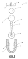
- FIG. 3 is a partial cross-sectional diagram of a compressible cup and wedge structures of the pedicle or other surgical screw system of FIG. 1 , according to one exemplary embodiment of the present invention.
- FIG. 4 is a partial cross-sectional diagram of the pedicle or other surgical screw system of FIG. 1 in a fully-engaged configuration, according to one exemplary embodiment of the present invention.
- the present invention relates to an alternatively monoaxial and polyaxial pedicle or other similar surgical screw that can be used in a polyaxial manner and then locked or otherwise secured at a desired angle or orientation, i.e. used in a monoaxial manner, prior to engaging a rod or other similar stabilization member with the pedicle or other similar surgical screw.
- the present invention provides a pedicle or other similar surgical screw that can be selectively used in either a monoaxial or polyaxial configuration, as is desirable in a particular application or at a particular point of a given surgical procedure.
- the pedicle screw includes a set screw that is configured to selectively compress a wedge structure, which then compresses a compressible cup, which then impinges on a head portion of the pedicle screw, thereby locking the “tulip” portion of the pedicle screw at a desired angle and orientation with respect to the threaded portion of the pedicle screw.
- a pedicle screw system 10 is illustrated according to one exemplary embodiment of the present invention. It will be readily apparent to those of ordinary skill in the art that the concepts illustrated and described herein can be extended to other surgical screw systems as well, provided that such surgical screw systems utilize surgical screws that have a “tulip” portion through which a stabilizing member is selectively disposed and secured and a threaded portion.
- the pedicle screw system 10 includes a pedicle screw 12 that includes a bone screw 14 and a screw head 16 .
- the pedicle screw 12 is configured to be selectively screwed into a bony anatomical structure of a patient, such as a pedicle of the spine or the like.
- the bone screw 14 includes appropriate threads or the like and the screw head 16 includes recesses or the like for engaging a driver tool, etc.
- the pedicle screw system 10 further includes a tulip assembly 20 concentrically formed/disposed around the screw head 16 , with the bone screw 14 protruding through downwardly through the bottom thereof.
- the tulip assembly 20 is configured to selectively fix (i.e. secure) a longitudinal stabilizing member 22 to the pedicle screw 12 at a desired angle and orientation.
- the stabilizing member 22 includes an elongate rod that is inserted through opposed openings manufactured into either side of the tulip assembly 20 , the elongate rod oriented substantially perpendicular to the axis of the pedicle screw 12 . Often, the elongate rod will physically contact the screw head 16 .
- the pedicle screw system 10 of the present invention also includes a compressible cup 30 or other sleeve structure disposed about the screw head 16 .
- the screw head 16 rests snugly inside the compressible cup 30 or other sleeve structure.
- the tulip assembly 20 includes wedges 32 , 34 disposed within the interior of the tulip assembly 20 .
- the wedges 32 , 34 extend substantially from the top of the tulip assembly 20 downwards towards the compressible cup 30 or other sleeve structure.
- the wedges 32 , 34 can be separate components or integrally formed.
- the wedges 32 , 34 can be joined at a common ring at their top ends, etc.
- the wedges 32 , 34 have a shape 36 that is configured to conformally mate with the surface of the compressible cup 30 or other sleeve structure.
- the tulip assembly 20 also includes an outer set screw 40 that is externally threaded and is operable to screw into the tulip assembly 20 , which is internally threaded, and exert a compressive force upon the tops of the wedges 32 , 34 .
- the wedges 32 , 34 compress the compressible cup 30 or other sleeve structure around the screw head 16 , thereby “locking” the tulip assembly 20 to the pedicle screw 12 through the screw head 16 .
- the outer set screw 40 drives the wedges 32 , 34 into the compressible cup 30 or other sleeve structure, which exerts compressive force on the screw head 16 , thereby securing the angle and orientation of the tulip assembly 20 with respect to the pedicle screw 12 .
- other means could be used to drive the wedges 32 , 34 or another compressive structure into the compressible cup 30 or other sleeve structure, causing it to exert a securing force on the screw head 16 .
- the tulip assembly 20 further includes an inner set screw 42 , optionally threaded through the outer set screw 40 , that is operable to “lock” the rod 22 to the wedges 32 , 34 through notches 44 manufactured or otherwise disposed the wedges 32 , 34 , or otherwise “lock” the rod 22 within the now immobilized tulip assembly 20 .
- the rod 22 is not required to itself apply a force to the screw head 16 , thereby eliminating the requirement for the rod 22 to be positioned or placed prior to “locking in” a desired angle of the tulip assembly 20 .
- the wedges 32 , 34 and the compressible cup 30 enable the pedicle screw system 10 to be lock at a desired angle without requiring the rod 22 to be “locked” in place. Additionally, the compressible cup 30 provides a better locking mechanism than other conventional systems by enabling the force from the wedges 32 , 34 to be evenly distributed to the screw head 16 as opposed to only on a top portion of the screw head 16 . It will be readily apparent to those of ordinary skill in the art that the compressible cup 30 can have a variety of configurations and can cover any desired percentage of the surface of the compressible cup 30 , and the wedges 32 , 34 can concentrically cover any desired percentage of the interior circumference of the tulip assembly 20 .
- FIG. 2 illustrates an expanded view of all of the components of the pedicle screw system 10 according to one exemplary embodiment of the present invention.
- the compressible cup 30 is placed over the bone screw 14 to the screw head 16 .
- the tulip assembly 20 is placed over the bone screw 14 without the wedges 32 , 34 .
- the wedges 32 , 34 are then placed within the tulip assembly 20 .
- the bone screw 14 is secured to a pedicle or the like, and the outer set screw 40 is utilized to position a desired angle of the pedicle screw system 10 , “locking” the pedicle screw 12 in place through the compressible cup 30 and the wedges 32 , 34 .
- the rod 22 is positioned and “locked” in place with the inner set screw 42 .
- the compressible cup 30 and the wedges 32 , 34 are illustrated according to one exemplary embodiment of the present invention.
- the outer set screw 40 (not shown in FIG. 3 ) is configured to exert a force 50 on each of the wedges 32 , 34 .
- This force 50 is translated to the compressible cup 30 , causing the compressible cup 30 to tightly “form” around the screw head 16 (not shown in FIG. 3 ).
- the present invention ensures the tulip assembly 20 (not shown in FIG. 3 ) is “locked” in place to the screw head 16 , and not solely “locked” to a top of the screw head 16 .
- the pedicle screw system 10 is illustrated in a fully deployed configuration according to one exemplary embodiment of the present invention.
- the wedges 32 , 34 are disposed tightly between the outer set screw 40 and the compressible cup 30 , thereby locking the tulip assembly 20 to the pedicle screw 12 .
- the rod 22 is positioned within the tulip assembly 20 , locked in place by the inner set screw 42 , the wedges 32 , 34 , and the screw head 16 .
- pedicle screw system 10 can operate as either monoaxial or polyaxial, selectively and alternatively. Further, multiple pedicle screw systems 10 can be used together to secure the rod 22 or a plurality of rods 22 .
Abstract
Description
Claims (31)
Priority Applications (2)
| Application Number | Priority Date | Filing Date | Title |
|---|---|---|---|
| US12/578,690 US8512382B2 (en) | 2008-10-14 | 2009-10-14 | Monoaxial and polyaxial pedicle screw |
| US13/971,719 US20130338717A1 (en) | 2008-10-14 | 2013-08-20 | Monoaxial and polyaxial pedicle screws and related methods |
Applications Claiming Priority (2)
| Application Number | Priority Date | Filing Date | Title |
|---|---|---|---|
| US10507908P | 2008-10-14 | 2008-10-14 | |
| US12/578,690 US8512382B2 (en) | 2008-10-14 | 2009-10-14 | Monoaxial and polyaxial pedicle screw |
Related Child Applications (1)
| Application Number | Title | Priority Date | Filing Date |
|---|---|---|---|
| US13/971,719 Division US20130338717A1 (en) | 2008-10-14 | 2013-08-20 | Monoaxial and polyaxial pedicle screws and related methods |
Publications (2)
| Publication Number | Publication Date |
|---|---|
| US20100094354A1 US20100094354A1 (en) | 2010-04-15 |
| US8512382B2 true US8512382B2 (en) | 2013-08-20 |
Family
ID=42099586
Family Applications (2)
| Application Number | Title | Priority Date | Filing Date |
|---|---|---|---|
| US12/578,690 Active 2031-07-03 US8512382B2 (en) | 2008-10-14 | 2009-10-14 | Monoaxial and polyaxial pedicle screw |
| US13/971,719 Abandoned US20130338717A1 (en) | 2008-10-14 | 2013-08-20 | Monoaxial and polyaxial pedicle screws and related methods |
Family Applications After (1)
| Application Number | Title | Priority Date | Filing Date |
|---|---|---|---|
| US13/971,719 Abandoned US20130338717A1 (en) | 2008-10-14 | 2013-08-20 | Monoaxial and polyaxial pedicle screws and related methods |
Country Status (1)
| Country | Link |
|---|---|
| US (2) | US8512382B2 (en) |
Cited By (6)
| Publication number | Priority date | Publication date | Assignee | Title |
|---|---|---|---|---|
| US20130338717A1 (en) * | 2008-10-14 | 2013-12-19 | Us Spine, Inc. | Monoaxial and polyaxial pedicle screws and related methods |
| US20150080963A1 (en) * | 2013-09-13 | 2015-03-19 | Chester H. Sharps | System and method for spinal deformity correction |
| EP3023064A1 (en) * | 2014-11-20 | 2016-05-25 | Biedermann Technologies GmbH & Co. KG | Receiving part for coupling a bone anchor to a rod and bone anchoring device with such a receiving part |
| US20170290607A1 (en) * | 2015-10-30 | 2017-10-12 | Huanyu Hu | Minimally invasive screw with double threaded plugs |
| US10052136B2 (en) | 2015-03-12 | 2018-08-21 | Amedica Corporation | Spring cage spinal fixation systems |
| US10820928B2 (en) | 2016-07-29 | 2020-11-03 | Zimmer Biomet Spine, Inc. | Bone screw threaded enlarger |
Families Citing this family (2)
| Publication number | Priority date | Publication date | Assignee | Title |
|---|---|---|---|---|
| US20120197312A1 (en) * | 2011-01-28 | 2012-08-02 | Warsaw Orthopedic, Inc. | Thread introduction features for an orthopedic implant |
| CN113171166B (en) * | 2021-04-26 | 2022-06-14 | 宁波兆盈医疗器械有限公司 | Multipurpose pedicle screw, preparation method and fixing method thereof |
Citations (5)
| Publication number | Priority date | Publication date | Assignee | Title |
|---|---|---|---|---|
| US5562663A (en) * | 1995-06-07 | 1996-10-08 | Danek Medical, Inc. | Implant interconnection mechanism |
| US6540749B2 (en) * | 2001-02-17 | 2003-04-01 | Bernd Schäfer | Bone screw |
| US20050203516A1 (en) * | 2004-03-03 | 2005-09-15 | Biedermann Motech Gmbh | Anchoring element and stabilization device for the dynamic stabilization of vertebrae or bones using such anchoring elements |
| US20050277927A1 (en) * | 2004-06-14 | 2005-12-15 | Guenther Kevin V | Fastening system for spinal stabilization system |
| US7896902B2 (en) * | 2006-04-05 | 2011-03-01 | Dong Myung Jeon | Multi-axial double locking bone screw assembly |
Family Cites Families (8)
| Publication number | Priority date | Publication date | Assignee | Title |
|---|---|---|---|---|
| DE19509332C1 (en) * | 1995-03-15 | 1996-08-14 | Harms Juergen | Anchoring element |
| US5964760A (en) * | 1996-10-18 | 1999-10-12 | Spinal Innovations | Spinal implant fixation assembly |
| DE59610225D1 (en) * | 1996-12-12 | 2003-04-17 | Synthes Ag | DEVICE FOR CONNECTING A LONG RACK TO A PEDICLE SCREW |
| US6641586B2 (en) * | 2002-02-01 | 2003-11-04 | Depuy Acromed, Inc. | Closure system for spinal fixation instrumentation |
| US7857834B2 (en) * | 2004-06-14 | 2010-12-28 | Zimmer Spine, Inc. | Spinal implant fixation assembly |
| BRPI0621728A2 (en) * | 2006-06-05 | 2012-10-16 | Traiber S L | vertebral fixation device and tool for mounting the same |
| WO2008008511A2 (en) * | 2006-07-14 | 2008-01-17 | Laszlo Garamszegi | Pedicle screw assembly with inclined surface seat |
| US8512382B2 (en) * | 2008-10-14 | 2013-08-20 | Us Spine, Inc. | Monoaxial and polyaxial pedicle screw |
-
2009
- 2009-10-14 US US12/578,690 patent/US8512382B2/en active Active
-
2013
- 2013-08-20 US US13/971,719 patent/US20130338717A1/en not_active Abandoned
Patent Citations (5)
| Publication number | Priority date | Publication date | Assignee | Title |
|---|---|---|---|---|
| US5562663A (en) * | 1995-06-07 | 1996-10-08 | Danek Medical, Inc. | Implant interconnection mechanism |
| US6540749B2 (en) * | 2001-02-17 | 2003-04-01 | Bernd Schäfer | Bone screw |
| US20050203516A1 (en) * | 2004-03-03 | 2005-09-15 | Biedermann Motech Gmbh | Anchoring element and stabilization device for the dynamic stabilization of vertebrae or bones using such anchoring elements |
| US20050277927A1 (en) * | 2004-06-14 | 2005-12-15 | Guenther Kevin V | Fastening system for spinal stabilization system |
| US7896902B2 (en) * | 2006-04-05 | 2011-03-01 | Dong Myung Jeon | Multi-axial double locking bone screw assembly |
Cited By (17)
| Publication number | Priority date | Publication date | Assignee | Title |
|---|---|---|---|---|
| US20130338717A1 (en) * | 2008-10-14 | 2013-12-19 | Us Spine, Inc. | Monoaxial and polyaxial pedicle screws and related methods |
| US20150080963A1 (en) * | 2013-09-13 | 2015-03-19 | Chester H. Sharps | System and method for spinal deformity correction |
| US9351770B2 (en) * | 2013-09-13 | 2016-05-31 | Chester H. Sharps | System and method for spinal deformity correction |
| CN105615971B (en) * | 2014-11-20 | 2020-09-01 | 比德尔曼技术有限责任两合公司 | Receiving part for coupling a bone anchor to a rod and bone anchoring device having such a receiving part |
| EP3023064A1 (en) * | 2014-11-20 | 2016-05-25 | Biedermann Technologies GmbH & Co. KG | Receiving part for coupling a bone anchor to a rod and bone anchoring device with such a receiving part |
| US20160143665A1 (en) * | 2014-11-20 | 2016-05-26 | Lutz Biedermann | Receiving part for coupling a bone anchor to a rod and bone anchoring device with such a receiving part |
| CN105615971A (en) * | 2014-11-20 | 2016-06-01 | 比德尔曼技术有限责任两合公司 | Receiving part for coupling a bone anchor to a rod and bone anchoring device with such a receiving part |
| US11197693B2 (en) | 2014-11-20 | 2021-12-14 | Biedermann Technologies Gmbh & Co. Kg | Receiving part for coupling a bone anchor to a rod and bone anchoring device with such a receiving part |
| US9861388B2 (en) * | 2014-11-20 | 2018-01-09 | Biedermann Technologies Gmbh & Co. Kg | Receiving part for coupling a bone anchor to a rod and bone anchoring device with such a receiving part |
| US10610260B2 (en) | 2014-11-20 | 2020-04-07 | Biedermann Technologies Gmbh & Co. Kg | Receiving part for coupling a bone anchor to a rod and bone anchoring device with such a receiving part |
| US10052136B2 (en) | 2015-03-12 | 2018-08-21 | Amedica Corporation | Spring cage spinal fixation systems |
| US10022156B2 (en) * | 2015-10-30 | 2018-07-17 | Beijing Fule Science & Technology Development Co., Ltd. | Minimally invasive screw with double threaded plugs |
| US20170290607A1 (en) * | 2015-10-30 | 2017-10-12 | Huanyu Hu | Minimally invasive screw with double threaded plugs |
| US10820928B2 (en) | 2016-07-29 | 2020-11-03 | Zimmer Biomet Spine, Inc. | Bone screw threaded enlarger |
| US10828070B2 (en) | 2016-07-29 | 2020-11-10 | Zimmer Biomet Spine, Inc. | Bone anchor housing limiter |
| US11707300B2 (en) | 2016-07-29 | 2023-07-25 | Zimmer Biomet Spine, Inc. | Bone screw threaded enlarger |
| US11877774B2 (en) | 2016-07-29 | 2024-01-23 | Zimmer Biomet Spine, Inc. | Bone anchor housing limiter |
Also Published As
| Publication number | Publication date |
|---|---|
| US20100094354A1 (en) | 2010-04-15 |
| US20130338717A1 (en) | 2013-12-19 |
Similar Documents
| Publication | Publication Date | Title |
|---|---|---|
| US8512382B2 (en) | Monoaxial and polyaxial pedicle screw | |
| US11432850B2 (en) | Polyaxial bone anchors with increased angulation | |
| US7704270B2 (en) | Variable offset connectors and bone fixation methods | |
| US7967845B2 (en) | Head-to-head connector spinal fixation system | |
| JP5078900B2 (en) | System for stabilizing bone parts | |
| EP1788962B1 (en) | Device for securing a spinal rod to the spine | |
| US7828829B2 (en) | Low top bone fixation system and method for using the same | |
| US8016866B2 (en) | Pedicle screw system with provisional locking aspects | |
| US6238396B1 (en) | Surgical cross-connecting apparatus and related methods | |
| JP4318421B2 (en) | Multiaxial bone screw assembly | |
| US8870922B2 (en) | Clamp for spinal cross connecting device | |
| US20050080415A1 (en) | Polyaxial bone anchor and method of spinal fixation | |
| US9387015B2 (en) | Vertebral osteosynthesis equipment | |
| US20080183223A1 (en) | Hybrid jointed bone screw system | |
| US20070135817A1 (en) | Percutaneous screw assembly | |
| JP2009532182A (en) | Horizontal connector assembly | |
| KR20090018679A (en) | Locking device for bone stabilization system |
Legal Events
| Date | Code | Title | Description |
|---|---|---|---|
| AS | Assignment |
Owner name: U.S. SPINE, INC.,FLORIDA Free format text: ASSIGNMENT OF ASSIGNORS INTEREST;ASSIGNOR:CAWLEY, TRACE;REEL/FRAME:023476/0115 Effective date: 20091105 Owner name: U.S. SPINE, INC., FLORIDA Free format text: ASSIGNMENT OF ASSIGNORS INTEREST;ASSIGNOR:CAWLEY, TRACE;REEL/FRAME:023476/0115 Effective date: 20091105 |
|
| AS | Assignment |
Owner name: U.S. SPINE, INC.,FLORIDA Free format text: ASSIGNMENT OF ASSIGNORS INTEREST;ASSIGNORS:SHARPS, CHESTER;TUTEN, HANS ROBERT;REEL/FRAME:024143/0913 Effective date: 20100318 Owner name: U.S. SPINE, INC., FLORIDA Free format text: ASSIGNMENT OF ASSIGNORS INTEREST;ASSIGNORS:SHARPS, CHESTER;TUTEN, HANS ROBERT;REEL/FRAME:024143/0913 Effective date: 20100318 |
|
| AS | Assignment |
Owner name: ZIONS FIRST NATIONAL BANK, UTAH Free format text: SECURITY AGREEMENT;ASSIGNOR:US SPINE, INC.;REEL/FRAME:025434/0317 Effective date: 20100917 |
|
| AS | Assignment |
Owner name: KARL KIPKE, AS COLLATERAL AGENT, TEXAS Free format text: SECURITY AGREEMENT;ASSIGNOR:AMEDICA CORPORATION;REEL/FRAME:025900/0168 Effective date: 20110303 |
|
| AS | Assignment |
Owner name: AMEDICA CORPORATION, UTAH Free format text: RELEASE BY SECURED PARTY;ASSIGNOR:AS COLLATERAL AGENT, KARL KIPKE;REEL/FRAME:029492/0321 Effective date: 20121214 Owner name: US SPINE, INC., UTAH Free format text: RELEASE BY SECURED PARTY;ASSIGNOR:ZIONS FIRST NATIONAL BANK;REEL/FRAME:029491/0085 Effective date: 20121217 Owner name: GE CAPITAL EQUITY INVESTMENTS, INC. C/O GE HEALTHC Free format text: SECURITY AGREEMENT;ASSIGNORS:AMEDICA CORPORATION;US SPINE, INC.;REEL/FRAME:029495/0211 Effective date: 20121214 |
|
| STCF | Information on status: patent grant |
Free format text: PATENTED CASE |
|
| AS | Assignment |
Owner name: GENERAL ELECTRIC CAPITAL CORPORATION, MARYLAND Free format text: CORRECTIVE ASSIGNMENT TO CORRECT THE NAME OF THE ASSIGNEE PREVIOUSLY RECORDED ON REEL 029495 FRAME 0211. ASSIGNOR(S) HEREBY CONFIRMS THE ASSIGNOR: AMEDICA CORPORATION ASSIGNOR: US SPINE, INC. ASSIGNEE: GENERAL ELECTRIC CAPITAL CORPORATION;ASSIGNORS:AMEDICA CORPORATION;US SPINE, INC.;REEL/FRAME:031581/0831 Effective date: 20121214 |
|
| FPAY | Fee payment |
Year of fee payment: 4 |
|
| AS | Assignment |
Owner name: AMEDICA CORPORATION, UTAH Free format text: ASSIGNMENT OF ASSIGNORS INTEREST;ASSIGNOR:U.S. SPINE, INC.;REEL/FRAME:044795/0780 Effective date: 20180127 |
|
| AS | Assignment |
Owner name: AMEDICA CORPORATION, UTAH Free format text: RELEASE BY SECURED PARTY;ASSIGNOR:GENERAL ELECTRIC CAPITAL CORPORATION;REEL/FRAME:047199/0313 Effective date: 20140630 Owner name: US SPINE, INC., UTAH Free format text: RELEASE BY SECURED PARTY;ASSIGNOR:GENERAL ELECTRIC CAPITAL CORPORATION;REEL/FRAME:047199/0313 Effective date: 20140630 |
|
| AS | Assignment |
Owner name: US SPINE, INC., UTAH Free format text: CORRECTIVE ASSIGNMENT TO CORRECT THE PATENT NUMBER PREVIOUSLY RECORDED AT REEL: 047199 FRAME: 0313. ASSIGNOR(S) HEREBY CONFIRMS THE RELEASE OF SECURITY INTEREST;ASSIGNOR:GENERAL ELECTRIC CAPITAL CORPORATION;REEL/FRAME:047403/0953 Effective date: 20140630 Owner name: AMEDICA CORPORATION, UTAH Free format text: CORRECTIVE ASSIGNMENT TO CORRECT THE PATENT NUMBER PREVIOUSLY RECORDED AT REEL: 047199 FRAME: 0313. ASSIGNOR(S) HEREBY CONFIRMS THE RELEASE OF SECURITY INTEREST;ASSIGNOR:GENERAL ELECTRIC CAPITAL CORPORATION;REEL/FRAME:047403/0953 Effective date: 20140630 |
|
| AS | Assignment |
Owner name: CTL MEDICAL CORPORATION, TEXAS Free format text: ASSIGNMENT OF ASSIGNORS INTEREST;ASSIGNORS:AMEDICA CORPORATION;U.S. SPINE, INC.;REEL/FRAME:051368/0261 Effective date: 20181001 |
|
| MAFP | Maintenance fee payment |
Free format text: PAYMENT OF MAINTENANCE FEE, 8TH YR, SMALL ENTITY (ORIGINAL EVENT CODE: M2552); ENTITY STATUS OF PATENT OWNER: SMALL ENTITY Year of fee payment: 8 |
|
| AS | Assignment |
Owner name: SOURCE CAPITAL CREDIT OPPORTUNITIES FUND III, LP, GEORGIA Free format text: SECURITY INTEREST;ASSIGNOR:CTL MEDICAL CORPORATION;REEL/FRAME:056417/0606 Effective date: 20210513 |
|
| AS | Assignment |
Owner name: STERLING NATIONAL BANK, NEW YORK Free format text: SECURITY AGREEMENT;ASSIGNOR:CTL MEDICAL CORPORATION;REEL/FRAME:056595/0562 Effective date: 20210513 |