US8403594B2 - Aggregate-spreading device - Google Patents
Aggregate-spreading device Download PDFInfo
- Publication number
- US8403594B2 US8403594B2 US13/597,933 US201213597933A US8403594B2 US 8403594 B2 US8403594 B2 US 8403594B2 US 201213597933 A US201213597933 A US 201213597933A US 8403594 B2 US8403594 B2 US 8403594B2
- Authority
- US
- United States
- Prior art keywords
- aggregate
- skeletal frame
- conveyor
- spreading device
- spreader
- Prior art date
- Legal status (The legal status is an assumption and is not a legal conclusion. Google has not performed a legal analysis and makes no representation as to the accuracy of the status listed.)
- Active
Links
- 238000003892 spreading Methods 0.000 title claims abstract description 117
- 230000000712 assembly Effects 0.000 claims abstract description 21
- 238000000429 assembly Methods 0.000 claims abstract description 21
- 238000012423 maintenance Methods 0.000 claims abstract description 10
- 230000002441 reversible effect Effects 0.000 claims abstract description 10
- 230000008439 repair process Effects 0.000 claims abstract description 9
- 238000004891 communication Methods 0.000 claims description 6
- 230000007480 spreading Effects 0.000 abstract description 4
- 239000004035 construction material Substances 0.000 abstract description 3
- 238000004519 manufacturing process Methods 0.000 abstract description 2
- 238000010276 construction Methods 0.000 description 12
- 230000033001 locomotion Effects 0.000 description 11
- 230000009977 dual effect Effects 0.000 description 6
- 238000003780 insertion Methods 0.000 description 5
- 230000037431 insertion Effects 0.000 description 5
- 238000012986 modification Methods 0.000 description 4
- 230000004048 modification Effects 0.000 description 4
- 238000013461 design Methods 0.000 description 3
- 239000000463 material Substances 0.000 description 3
- 238000007792 addition Methods 0.000 description 2
- 239000010426 asphalt Substances 0.000 description 2
- 230000008901 benefit Effects 0.000 description 2
- 239000004568 cement Substances 0.000 description 2
- 238000004140 cleaning Methods 0.000 description 2
- 230000008707 rearrangement Effects 0.000 description 2
- 239000004576 sand Substances 0.000 description 2
- 239000002689 soil Substances 0.000 description 2
- 239000004575 stone Substances 0.000 description 2
- 230000005540 biological transmission Effects 0.000 description 1
- 230000000694 effects Effects 0.000 description 1
- 239000012530 fluid Substances 0.000 description 1
- 230000014759 maintenance of location Effects 0.000 description 1
- 230000007246 mechanism Effects 0.000 description 1
- 238000003860 storage Methods 0.000 description 1
- 238000005728 strengthening Methods 0.000 description 1
- 238000012546 transfer Methods 0.000 description 1
Images


Classifications
-
- E—FIXED CONSTRUCTIONS
- E01—CONSTRUCTION OF ROADS, RAILWAYS, OR BRIDGES
- E01C—CONSTRUCTION OF, OR SURFACES FOR, ROADS, SPORTS GROUNDS, OR THE LIKE; MACHINES OR AUXILIARY TOOLS FOR CONSTRUCTION OR REPAIR
- E01C19/00—Machines, tools or auxiliary devices for preparing or distributing paving materials, for working the placed materials, or for forming, consolidating, or finishing the paving
- E01C19/12—Machines, tools or auxiliary devices for preparing or distributing paving materials, for working the placed materials, or for forming, consolidating, or finishing the paving for distributing granular or liquid materials
- E01C19/20—Apparatus for distributing, e.g. spreading, granular or pulverulent materials, e.g. sand, gravel, salt, dry binders
- E01C19/201—Apparatus for distributing, e.g. spreading, granular or pulverulent materials, e.g. sand, gravel, salt, dry binders with driven loosening, discharging or spreading parts, e.g. power-driven, drive derived from road-wheels
- E01C19/2045—Apparatus for distributing, e.g. spreading, granular or pulverulent materials, e.g. sand, gravel, salt, dry binders with driven loosening, discharging or spreading parts, e.g. power-driven, drive derived from road-wheels spreading by means of an endless belt or like conveyor
-
- E—FIXED CONSTRUCTIONS
- E01—CONSTRUCTION OF ROADS, RAILWAYS, OR BRIDGES
- E01C—CONSTRUCTION OF, OR SURFACES FOR, ROADS, SPORTS GROUNDS, OR THE LIKE; MACHINES OR AUXILIARY TOOLS FOR CONSTRUCTION OR REPAIR
- E01C19/00—Machines, tools or auxiliary devices for preparing or distributing paving materials, for working the placed materials, or for forming, consolidating, or finishing the paving
- E01C19/12—Machines, tools or auxiliary devices for preparing or distributing paving materials, for working the placed materials, or for forming, consolidating, or finishing the paving for distributing granular or liquid materials
- E01C19/15—Machines, tools or auxiliary devices for preparing or distributing paving materials, for working the placed materials, or for forming, consolidating, or finishing the paving for distributing granular or liquid materials for laying-down uncoated stone or similar materials, or for striking-off or spreading same without compacting, e.g. for crushed rock base courses, sand cushions for paving
-
- E—FIXED CONSTRUCTIONS
- E01—CONSTRUCTION OF ROADS, RAILWAYS, OR BRIDGES
- E01C—CONSTRUCTION OF, OR SURFACES FOR, ROADS, SPORTS GROUNDS, OR THE LIKE; MACHINES OR AUXILIARY TOOLS FOR CONSTRUCTION OR REPAIR
- E01C19/00—Machines, tools or auxiliary devices for preparing or distributing paving materials, for working the placed materials, or for forming, consolidating, or finishing the paving
- E01C19/12—Machines, tools or auxiliary devices for preparing or distributing paving materials, for working the placed materials, or for forming, consolidating, or finishing the paving for distributing granular or liquid materials
- E01C19/20—Apparatus for distributing, e.g. spreading, granular or pulverulent materials, e.g. sand, gravel, salt, dry binders
- E01C19/201—Apparatus for distributing, e.g. spreading, granular or pulverulent materials, e.g. sand, gravel, salt, dry binders with driven loosening, discharging or spreading parts, e.g. power-driven, drive derived from road-wheels
-
- E—FIXED CONSTRUCTIONS
- E01—CONSTRUCTION OF ROADS, RAILWAYS, OR BRIDGES
- E01C—CONSTRUCTION OF, OR SURFACES FOR, ROADS, SPORTS GROUNDS, OR THE LIKE; MACHINES OR AUXILIARY TOOLS FOR CONSTRUCTION OR REPAIR
- E01C19/00—Machines, tools or auxiliary devices for preparing or distributing paving materials, for working the placed materials, or for forming, consolidating, or finishing the paving
- E01C19/12—Machines, tools or auxiliary devices for preparing or distributing paving materials, for working the placed materials, or for forming, consolidating, or finishing the paving for distributing granular or liquid materials
- E01C19/20—Apparatus for distributing, e.g. spreading, granular or pulverulent materials, e.g. sand, gravel, salt, dry binders
- E01C2019/2055—Details not otherwise provided for
- E01C2019/207—Feeding the distribution means
- E01C2019/2085—Feeding the distribution means with transverse conveyor belt
-
- E—FIXED CONSTRUCTIONS
- E01—CONSTRUCTION OF ROADS, RAILWAYS, OR BRIDGES
- E01C—CONSTRUCTION OF, OR SURFACES FOR, ROADS, SPORTS GROUNDS, OR THE LIKE; MACHINES OR AUXILIARY TOOLS FOR CONSTRUCTION OR REPAIR
- E01C19/00—Machines, tools or auxiliary devices for preparing or distributing paving materials, for working the placed materials, or for forming, consolidating, or finishing the paving
- E01C19/12—Machines, tools or auxiliary devices for preparing or distributing paving materials, for working the placed materials, or for forming, consolidating, or finishing the paving for distributing granular or liquid materials
- E01C19/20—Apparatus for distributing, e.g. spreading, granular or pulverulent materials, e.g. sand, gravel, salt, dry binders
- E01C2019/2055—Details not otherwise provided for
- E01C2019/207—Feeding the distribution means
- E01C2019/2095—Feeding the distribution means by tipping
Definitions
- Another feature of known devices is that they are self-propelled. Many of the devices include large engines with transmissions for moving the device. This adds considerable costs as well as weight to the device.
- What is therefore needed in the road construction industry is a low-cost device that may be either pushed by another vehicle such as a skid steer or attached to a rear end of an aggregate storage vehicle such as a dump truck, thus eliminating the need for an engine and drivetrain. Also needed is a device that eliminates hydraulics and utilizes electronic actuators and electronic motors for operation of the device. Another feature needed is a device that is constructed in a lightweight design, allowing for easier mobility, repairs, and maintenance.
- One object of the invention is to provide an aggregate-spreading device that may be attached either to a vehicle such as a skid steer and pushed behind a dump truck or suspended directly to the rear of a vehicle such as a dump truck, allowing the aggregate-spreading device to receive aggregate from the dump truck.
- a spreader assembly may be attached on either both sides of the device or on a single side.
- the spreader assemblies are configured to extend and retract to and from the device and also may pivot allowing an angular adjustment. This movement may be accomplished with the use of electronic actuators, allowing an operator to have precise control over the width and depth of the aggregate that is spread.
- a conveyor may be controlled with the controller to rotate in one direction for supplying aggregate to a spreader assembly on one side of the device, and controlled to reverse the rotation so as to supply aggregate to a spreader assembly on the opposite side of the device. This allows for the same device to be used when spreading aggregate on either side of the road while operating the machine in any desired direction.
- the device is constructed on a skeletal frame with various components attaching to the frame including a height adjustable hopper. This allows for a modular construction and assists maintenance and repair work as various components may be removed or replaced with ease. Manufacturing costs are also lowered as is the overall weight of the device.
- Another object of the invention is to provide an apparatus that has one or more of the characteristics discussed above in various combinations, thus, allowing for a reduced labor time and labor effort when spreading aggregate on a job site.
- FIG. 1 illustrates an orthogonal view of the inventive aggregate-spreading device with a dual spreader assembly
- FIG. 2 illustrates a back view of the aggregate-spreading device of FIG. 1 ;
- FIG. 3 illustrates a front view of the aggregate-spreading device of FIG. 1 ;
- FIG. 4 illustrates a side view of the aggregate-spreading device of FIG. 1 ;
- FIG. 5 illustrates a top view of the aggregate-spreading device of FIG. 1 ;
- FIG. 6 illustrates a bottom view of the aggregate-spreading device of FIG. 1 ;
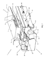
- FIG. 7 illustrates another orthogonal view of the aggregate-spreading device of FIG. 1 ;
- FIG. 8 illustrates an orthogonal view of a conveyor drive unit assembly of the invention
- FIG. 9 illustrates an orthogonal view of the skeletal frame for an aggregate-spreading machine with a single spreader assembly
- FIG. 10 illustrates an orthogonal view of the aggregate-spreading device equipped with a single spreader assembly
- FIG. 11 illustrates a bottom view of the aggregate-spreading device of FIG. 10 ;
- FIG. 12 illustrates a back view of the aggregate-spreading device of FIG. 10 ;
- FIG. 13 illustrates a front view of the aggregate-spreading device of FIG. 10 ;
- FIG. 14 illustrates a top view of the aggregate-spreading device of FIG. 10 ;
- FIG. 15 illustrates an orthogonal view of the aggregate-spreading device of FIG. 1 in operation while attached to a skid steer;
- FIG. 16 illustrates an orthogonal view of the aggregate-spreading device of FIG. 1 in operation while attached to a rear end of a dump truck.
- the present invention is directed to a device for spreading aggregate such as gravel on the side of the road.
- An effect of the present invention is to allow a road construction crew to widen or create a shoulder or road while minimizing the amount of time and labor required.
- One aspect of the invention is to provide an apparatus that is constructed on a skeletal frame and incorporates electronic motors and electronic actuators. Such an apparatus has the ability to spread aggregate all while being controlled with a manual controller that may be located remotely.
- the manual controller controls the electronics including electronic actuators and electronic motors to vary a conveyor speed, vary the conveyor's rotation direction, and control movement of the spreader assemblies.
- An aggregate-spreading device is disclosed with a first and a second spreader assembly.
- the aggregate-spreading device is built on a skeletal frame.
- a hopper, for receiving an aggregate from a vehicle such as a dump truck is attached to the skeletal frame by a single hopper support bar for receiving the aggregate.
- Aggregate is understood to include a multitude of construction materials including, but not limited to, gravel, sand, soil, stone, hot asphalt, crushed cement, wet cement, and any other material used to construct roads.
- a tailgate stop extends from the support bar for limiting the dump truck's tailgate from over-extending and spilling aggregate onto undesired locations.
- a tailgate stop prevents the tailgate of the dump truck from opening beyond a desired amount and assures that aggregate is only supplied into the hopper.
- the hopper is constructed of a front wall, a back wall, and a cutout wall on each side of the hopper.
- the cutout walls include a cutout.
- a conveyor drive unit assembly is attached to the skeletal frame at either end of the conveyor, or may be attached at both ends of the conveyor, by threaded rods that attach to insertion points. This allows the conveyor drive unit assembly to be positionable, varying the tension of the conveyor.
- the conveyor drive unit assembly drives the conveyor in a rotating motion.
- the conveyor rotates by wrapping around conveyor drive which is made up of a plurality of T-shaped extensions that converge on a single roller that is supported by a bearing on each end of the single roller.
- the conveyor drive is rotated by a conveyor motor.
- the conveyor motor may transfer rotating motion directly to the single roller with a chain that attaches to the single roller in between a first bearing plate and a second bearing plate.
- the conveyor rotates surrounding a path that includes a plurality of rollers that are supported on the skeletal frame by roller mounts.
- the conveyor motor may also be a reversible motor that rotates the conveyor, plurality of rollers, and conveyor drive in a first direction and may reverse rotation to rotate the conveyor in a second direction. This allows aggregate to be delivered to either side of the aggregate-spreading device.
- a conveyor shield protects the edges of the conveyor.
- a chain shield protects the chain from any foreign objects.
- a first spreader assembly attached to a first end of the skeletal frame may be extended to and from the skeletal frame for controlling how wide aggregate will be spread from the skeletal frame.
- a second spreader assembly attaches to a second end of the skeletal frame opposite the first end and also includes a variable extension distance from the skeletal frame.
- the aggregate-spreading device may be controlled by any electronic device, preferably a controller in communication with the conveyor motor, the first spreader assembly, and the second spreader assembly.
- the aggregate-spreading device may also be equipped with either hydraulics, electronic actuators, or a combination thereof for controlling the movement of the spreader assemblies.
- the controller may operate in a wireless fashion and be located inside a dump truck that supplies aggregate to the aggregate-spreading device, inside a vehicle such as a skid steer that pushes the aggregate-spreading device, or anywhere an operator may wish to be while controlling the device.
- the controller is preferably operated by a user with manual inputs and may be mounted inside the skid steer or dump truck or simply handheld.
- the controller may be operated to control the rotation of the conveyor to supply aggregate to the first spreader assembly when rotating in one direction and supply aggregate to the second spreader assembly when rotating in the opposite direction, control the conveyor rotation speed, and also control movement of the spreader assemblies.
- the controller controls the aggregate-spreading assemblies by communicating with a plurality of electronic actuators.
- the electronic actuators provide power to pistons that extend the aggregate-spreading assemblies to and from the skeletal frame and also provide an angular adjustment.
- each spreader assembly is equipped with a piston, chain, and angular adjustment guide.
- the first spreader assembly includes a first spreader plate, a first spreader extension connected to the first spreader plate at approximately a right angle, a first chain attaching an end of the spreader plate to the skeletal frame, a first piston, and an angular adjustment guide.
- Also included in the second spreader assembly is a second spreader plate, a second piston, a second chain, an angular adjust guide, and a second spreader extension.
- the conveyor which delivers the aggregate to either the first spreader assembly or the second spreader assembly depending on the inputs provided to the controller by an operator.
- the spreader assemblies may be moved in a manner placing the first or second spreader plate closer or further away from the skeletal frame by extending or retracting the piston with input to the controller, and the spreader assemblies may be adjusted with an angular adjustment.
- This angular adjustment allows the spreader assemblies to tilt in the vertical direction so that the first spreader plate or the second spreader plate is closer or further away from the ground.
- the angular adjustment guides provide a maximum and a minimum adjustment distance as well.
- the first and second chains are attached to the skeletal frame and may be attached to the first or second spreader plates to provide additional support under the weight of supplied aggregate and the weight of the extended spreader assemblies themselves.
- the aggregate-spreading device may be fastened to the front of a vehicle such as a skid steer but may optionally be fastened to any vehicle and pushed behind a dump truck.
- Contact rollers attached to the skeletal frame on the front side of the aggregate-spreading device are designed to allow contact with the rear wheels of the dump truck and rotate when in contact.
- the aggregate-spreading device may also be attached directly to the rear end of a dump truck by attaching the auxiliary mounting plate to any attachment point on the rear end of the dump truck, such as a trailer hitch.
- the aggregate-spreading device also has a set of wheels allowing it to roll on the road as it is suspended behind the dump truck or pushed by a skid steer. Attaching the aggregate-spreading device directly to the rear of a dump truck eliminates the need for an additional vehicle and also lowers the labor force required to widen roads and spread aggregate.
- the skeletal frame of the aggregate-spreading device is strengthened by attachment of a plurality of plates to form an exterior skin on the skeletal frame.
- the plates include, for example, a front plate and extension; however, any number of plates may be attached to the skeletal frame.
- the plurality of plates provide structural support to the skeletal frame, and because they may be removed and re-attached, they allow for simplified repairs, simplified assembly operations, and simplified maintenance operations as compared to other construction machines that do not include a skeletal frame and plate construction.
- a similar aggregate-spreading device is also disclosed, however, it is equipped with a single spreader assembly on a single end of the device.
- the device with a single spreader assembly functions identically to the device discussed above, but simply has a single spreader assembly. As there is only one spreader assembly, the conveyor only delivers aggregate to that side of the device.
- the hopper also includes one cutout wall with the cutout on the side of the device with the spreader assembly.
- the spreader assembly is similarly equipped with a spreader plate, spreader extension, piston, and chain, and operates identically to the spreader assemblies discussed above.
- an aggregate-spreading device 1 is disclosed.
- the aggregate-spreading device 1 is constructed on a skeletal frame 10 with a plurality of plates attached to the exterior of the skeletal frame 10 , including a front plate 33 and an extension 50 , however, any number of additional plates may also be attached to the skeletal frame for increased rigidity and protection from damage.
- a hopper support bar 12 is also attached to the skeletal frame 10 by a hopper support bar 12 , better seen in FIG. 2 , is a hopper 5 .
- the hopper 5 is constructed out of a back wall 7 , a front wall 6 , and cutout walls 9 .
- the cut out walls 9 each includes a cutout 4 .
- the hopper 5 is configured for receiving aggregate and delivering it to a conveyor 30 below.
- Aggregate is understood to include a multitude of construction materials including, but not limited to, top soil, wet concrete, hot asphalt, sand, gravel, crushed concrete, recycled materials, stone, and any other material used in road construction.
- a conveyor shield 32 guards the edge of the conveyor 30 and a chain shield 31 protects the conveyor's drive chain.
- the aggregate-spreading device 1 may be attached to the front of the vehicle, for example a skid steer 61 , and pushed from behind with the use of a universal mount 45 as shown in FIG. 15 . In this configuration, the skid steer pushes the aggregate-spreading device 1 behind the dump truck 59 that supplies aggregate to the hopper 5 .
- a pair of contact rollers 55 is designed to contact the rear wheels of the aggregate-supplying vehicle and to rotate along with the rear wheels of the vehicle.
- the auxiliary mounting plate 53 attached to the front of the aggregate-spreading device 1 may engage with the rear of the aggregate-supplying vehicle, for example a dump truck 59 , suspending the aggregate-spreading device 1 aggregate-supplying vehicle, as shown in FIG. 16 .
- This alternative configuration eliminates the need for an additional vehicle to push the aggregate-spreading device 1 .
- a pair of wheels 60 allows the aggregate-spreading device to roll along the ground as it moves; however, any number of wheels may be attached to the device for added support.
- the second spreader assembly 25 is also visible and is configured to spread aggregate that is supplied from the conveyor 30 .
- the second spreader assembly 25 includes a second spreader plate 26 , a second spreader extension 29 that is attached to the second spreader plate 26 at a right angle, and a second chain 28 .
- the second chain 28 is attached to the skeletal frame 10 on one end and the may be attached to the second spreader plate 26 at any other in order to provide additional support to the second spreader plate 26 under the load of aggregate.
- the aggregate-spreading device 1 is shown from the rear.
- the hopper 5 is attached to sleeve hopper support bar 12 on the skeletal frame 10 .
- a tailgate stop 11 Proximate to the hopper support bar 12 is a tailgate stop 11 which prevents a dump truck's tailgate from opening beyond a desired amount as it supplies aggregate to the hopper. This limits the aggregate to being supplied only to the hopper and not to the surrounding areas.
- Both spreader assemblies, first spreader assembly 20 , and second spreader assembly 25 are visible.
- First spreader assembly 20 is identical to the second spreader assembly 25 except it is attached to the opposite side of the skeletal frame 10 .
- the first spreader assembly also includes a first piston 22 that can extend and retract the first spreader plate 21 to and from the skeletal frame 10 .
- a first chain 23 is attached to the skeletal frame 10 and may be attached to the first spreader 21 anywhere in between the first end and the second end for supporting the weight of the first spreader assembly when extended.
- Second spreader assembly 25 also includes a second piston 27 that is configured to extend and retract the second spreader plate 26 to and from the skeletal frame 10 .
- Both spreader assemblies 20 , 25 may be adjusted to include an angular adjustment 19 that pivots the spreader assemblies 20 , 25 about a central axis of the aggregate-spreading device 1 , allowing the first spreader plate 21 and the second spreader plate 26 to have adjustable heights from the ground.
- the slope attachments 13 allow attachment of a ratcheting device from the slope attachment 13 to either spreader assembly 20 , 25 to reinforce the positioning of the angular adjustment 19 .
- An angular adjustment guide 47 on both the first spreader assembly 20 and the second spreader assembly 25 controls the maximum and minimum angular adjustment.
- the universal mount 45 is also shown and is configured to attach to a vehicle for pushing the aggregate-spreading device 1 behind a vehicle that supplies the hopper 5 with aggregate.
- the hopper 5 is suspended above the skeletal frame 10 by the hopper support bar 12 .
- the front plate 33 not only reinforces the skeletal frame 10 but also provides a mounting location for both contact rollers 55 and auxiliary mounting plate 53 .
- the first spreader assembly 20 and the second spreader assembly 25 receive aggregate delivered to the aggregate-spreading device 1 and are controlled to extend, retract, and adjust in an angular direction with the use of a controller 57 seen in FIGS. 15 and 16 .
- the controller 57 may be wired to the aggregate-spreading device 1 but is preferably a wireless controller, allowing the controller to be located in the aggregate-supplying vehicle or in the vehicle pushing the aggregate-spreading device 1 .
- the hopper 5 includes a cutout 4 on the cutout wall 9 .
- the cutout 4 may be covered or opened to assist aggregate to spill to the desired spreader assembly.
- a slope attachment 13 allows attachment of a ratcheting device from the slope attachment 13 to either spreader assembly for assisting in making the angular adjustment 19 discussed above.
- the hopper 5 is attached to the skeletal frame 10 by a single point by the hopper support bar 12 .
- the tailgate stop 11 is extendable and limits the motion of a dump truck's tailgate.
- FIG. 5 shows an overhead view of the aggregate-spreading device 1 .
- the hopper 5 is suspended directly over the conveyor 30 .
- the conveyor 30 is chain driven to rotate in both directions.
- FIG. 6 shows a bottom view of the aggregate-spreading device 1 .
- the rotation of the conveyor 30 is powered by a conveyor motor 56 .
- the conveyor motor 56 is directly controlled by the controller 57 . This allows the operator to control the rotational direction of the conveyor 30 from any location.
- the conveyor 30 is supported by and assisted in rotating with the help of a plurality of rollers 41 that are attached to the skeletal frame 10 on each end.
- the rollers 41 are preferably ball bearing rollers to minimize friction and assist the conveyor 30 in rotating.
- the rotation of the conveyor 30 is powered and made possible by a conveyor drive unit assembly 35 , shown in detail in FIG. 8 , located at each end of the conveyor 30 .
- the rollers 41 and conveyor motor 56 attach to the skeletal frame by interlocking with a plurality of roller mounts 43 , seen in FIG. 9 , that are located on the skeletal frame 10 at each end of the rollers 41 and conveyor motor 46 .
- the aggregate-spreading device 1 is equipped with a plurality of electronic actuators 54 for moving the first spreader assembly 20 and the second spreader assembly 25 .
- Electronic actuators 54 control the first piston 22 and the second piston 27 along with the angular adjustment 19 to allow an operator precise control over any movement of the spreader assemblies 20 , 25 with the use of the controller 57 .
- FIG. 7 shows an orthographic view of the aggregate-spreading device 1 .
- Both of the first spreader assembly 20 and the second spreader assembly 25 can be seen.
- Angular adjustment guides 47 prevent over adjustment in the angular direction of the first and second spreader assemblies 20 , 25 .
- a front plate support 34 acts as a truss and supports the skeletal frame 10 under the load of aggregate or when being pushed from behind or suspended from an aggregate spending vehicle. While only a single front plate support 34 is seen, there are many more front plate supports, as seen in FIG. 9 .
- the conveyor drive unit assembly 35 is shown.
- the conveyor drive unit assembly 35 is attached to the skeletal frame 10 with a pair of threaded rods 39 for securing the drive unit assembly to the skeletal frame 10 .
- the conveyor drive unit assembly 35 is attached to skeletal frame 10 on any side proximate to a spreader assembly.
- the conveyor drive unit assembly 35 includes a conveyor drive 40 that is made up of a plurality of T-shaped extensions that extend from a central axis of the conveyor drive 40 and converge on a single roller 48 to form a rotating drum.
- the single roller 48 has a bearing 36 on each end to assist in rotation.
- a first bearing plate 37 and a second bearing plate 38 on the ends of the single roller 48 assist in supporting the load of the conveyor drive 40 .
- a chain may be used to rotate the conveyor drive 40 .
- the chain interacts with a gear in between the first bearing plate 37 and the second bearing plate 38 that is attached to the single roller 48 .
- FIG. 9 shows an orthographic view of the skeletal frame according to one embodiment of the invention. While the skeletal frame disclosed in FIG. 9 is very similar to the skeletal frame of the aggregate-spreading device disclosed in FIGS. 1-7 above, it is equipped for a single spreader assembly 14 , shown in FIGS. 10-14 . The concept is identical to the skeletal frame of the dual spreader assembly design disclosed in FIGS. 1-7 . The only difference in the skeletal frame 10 design for the dual spreader assembly aggregate-spreading device is that the spreader attachment 3 as seen in FIG. 9 would be on both sides of the skeletal frame 10 , along with another angular adjustment guide 47 and electronic actuator 54 . As the skeletal frame 10 shown in FIG.
- the conveyor drive assembly mount 44 may be seen on the opposite side.
- the conveyor drive assembly mount 44 allows for simple attachment of the conveyor drive unit assembly 35 to the skeletal frame 10 .
- Mount bars 39 are inserted into the mount insertion point 42 for positive retention and location of the conveyor drive unit assembly 35 to the skeletal frame 10 .
- a plurality of front plate supports 34 functions as trusses to support the load on the skeletal frame 10 when the device is in use.
- the skeletal frame 10 also allows for easy repair and maintenance work to the aggregate-spreading device 1 as all the components may be removed from the skeletal frame 10 .
- the skeletal frame 10 also makes the aggregate-spreading device 1 much lighter in weight as compared to previous devices that did not incorporate a skeletal frame 10 .
- FIG. 10 shows an orthographic view of an aggregate-spreading device 1 that includes a single spreader assembly 14 .
- the side of the aggregate-spreading device 1 is exposed and other features may be seen.
- the conveyor drive unit assembly 35 can be seen along with a threaded rod 39 that is attached to a threaded rod insertion point 42 . While only a single conveyor drive unit assembly 35 is seen, all aggregate-spreading devices 1 optimally are equipped with a conveyor drive unit assembly 35 on each end of the conveyor 30 .
- a side plate 52 strengthens the skeletal frame 10 and prevents aggregate from falling off the conveyor 30 on the side of the aggregate-spreading device 1 that does not include a spreader assembly 14 .
- a back plate 51 and extension 50 also strengthen the skeletal frame 10 .
- the various plates strengthening the skeletal frame may be removed and reattached in order to assist maintenance, repair, and cleaning of the aggregate-spreading device 1 .
- the spreader assembly 14 may be extended to and from the skeletal frame 10 with the use of piston 16 .
- the piston 16 may also angularly adjust 19 the spreader assembly 14 exactly as is shown and discussed in FIG. 2 and above.
- An angular-adjustment guide 47 is equipped to prevent over adjusting when making angular adjustments.
- FIG. 11 a bottom view of the aggregate-spreading device 1 with a single spreader assembly 14 is shown.
- a plurality of rollers 41 assists the conveyor 30 in rotating.
- a conveyor motor 56 provides power to rotate the conveyor 30 preferably with the use of the chain attaching to the conveyor drive unit assembly 35 .
- An electronic actuator 54 powers the movements of the spreader assembly 14 just as disclosed in the dual spreader assembly embodiment above.
- Electronic actuator 54 is controlled by a controller 57 that is preferably wireless and is also in communication with the conveyor motor 56 to control all functions of the conveyor motor and movement of the spreader assembly 14 with manual input from the operator.
- the controller 57 may be located anywhere, an operator may manually control the functions of the aggregate-spreading device 1 from a vehicle pushing the device from the rear or, alternatively, for a vehicle supplying aggregate to the aggregate-spreading device 1 in the front.
- the aggregate spring device 1 may be attached to the vehicle in front of the device via auxiliary mounting plate 53 , suspending the aggregate-spreading device 1 from the rear of the vehicle.
- the aggregate-spreading device 1 may be attached to a vehicle pushing the device from the rear by attaching a vehicle to the universal mount 45 . This optional configuration allows the aggregate-spreading device 1 as disclosed in FIGS. 1-7 or in FIGS.
- the controller 57 may be located in the cabin of the dump truck 59 or in the skid steer 61 allowing the operator of either vehicle to operate the functions of the aggregate-spreading device 1 .
- a means for viewing is preferably used that enables the operator to see the aggregate coming out of the dump truck 59 and being supplied to any spreader assembly.
- the means for viewing may include a simple device such as a plurality of mirrors or a more sophisticated device such as video cameras mounted on the aggregate-spreading device 1 and monitors located inside the cabin of the respective vehicle.
- Such a configuration allows for a single person to operate the dump truck 59 and operate the aggregate-spreading device 1 when the aggregate-spreading device 1 is attached to the dump truck 59 as shown in FIG. 16 .
- FIG. 12 shows a rear side view of the aggregate-spreading device 1 that includes a single spreader assembly 14 .
- the conveyor drive unit assembly 35 , bearing 36 , threaded rod 39 , and threaded rod insertion point 42 are exposed on the opposite side of the skeletal frame 10 .
- the hopper 5 is attached to the skeletal frame 10 by the hopper support bar 12 .
- FIG. 13 discloses a front side view of the aggregate-spreading device 2 with a single spreader assembly 14 , just as with the dual spreader configuration of FIGS. 1-7 .
- the single spreader device includes a pair of contact rollers 55 attached to the front plate 33 .
- the contact rollers 55 are designed to contact the rear wheels of a dump truck 59 , as shown in FIG. 15 , when the device is pushed from the rear with attachment of a skid steer 61 via the auxiliary universal mount 45 .
- the wheels 60 allow the aggregate-spreading device 1 to roll on the ground as it is pushed by the skid steer 61 or when the device is suspended from the rear end of a dump truck as seen in FIG. 16 via the auxiliary mounting plate 53 .
- the hopper 5 receives aggregate from a dump truck 59 , as seen in FIGS. 15 and 16 , and is suspended above the conveyor 30 , as seen in FIG. 14 , by a single attachment point, the hopper support bar 12 .
- the spreader assembly 14 operates as discussed above.
- FIG. 14 A top side view of the aggregate-spreading device 1 with a single spreader assembly 14 is seen in FIG. 14 .
- the side wall 8 , front wall 6 , cutout wall 9 , and rear wall 7 are shown.
- Aggregate supplied to the hopper 5 is directed to fall directly on the conveyor 30 for delivery to the single spreader assembly 14 as the conveyor is rotated by the conveyor drive unit assembly 35 .
- the bearing 36 assists the conveyor drive unit assembly 35 in rotation and the threaded rod insertion point 42 secures the threaded rod 39 , seen in FIG. 8 , to the skeletal frame 10 thus allowing the conveyor drive unit assembly 35 to be positionable for adjusting the tension of the conveyor 30 .
- the universal mount 45 secured to the skeletal frame 10 and reinforced by the extension 50 , allows attachment of the aggregate-spreading device 1 to a vehicle such as a skid steer 61 , as seen in FIG. 15 .
- the aggregate-spreading device 1 may alternatively be secured to the rear side of a dump truck 59 with the auxiliary mounting plate 53 , as shown in FIG. 16 .
Abstract
Description
Claims (20)
Priority Applications (1)
| Application Number | Priority Date | Filing Date | Title |
|---|---|---|---|
| US13/597,933 US8403594B2 (en) | 2010-06-11 | 2012-08-29 | Aggregate-spreading device |
Applications Claiming Priority (2)
| Application Number | Priority Date | Filing Date | Title |
|---|---|---|---|
| US12/813,770 US8322947B2 (en) | 2010-06-11 | 2010-06-11 | Flexible skid steer attachment device |
| US13/597,933 US8403594B2 (en) | 2010-06-11 | 2012-08-29 | Aggregate-spreading device |
Related Parent Applications (1)
| Application Number | Title | Priority Date | Filing Date |
|---|---|---|---|
| US12/813,770 Division US8322947B2 (en) | 2010-06-11 | 2010-06-11 | Flexible skid steer attachment device |
Publications (2)
| Publication Number | Publication Date |
|---|---|
| US20130017017A1 US20130017017A1 (en) | 2013-01-17 |
| US8403594B2 true US8403594B2 (en) | 2013-03-26 |
Family
ID=45096347
Family Applications (3)
| Application Number | Title | Priority Date | Filing Date |
|---|---|---|---|
| US12/813,770 Active 2030-07-21 US8322947B2 (en) | 2010-06-11 | 2010-06-11 | Flexible skid steer attachment device |
| US13/597,933 Active US8403594B2 (en) | 2010-06-11 | 2012-08-29 | Aggregate-spreading device |
| US14/560,816 Active 2030-07-21 USRE46971E1 (en) | 2010-06-11 | 2014-12-04 | Flexible skid steer attachment device |
Family Applications Before (1)
| Application Number | Title | Priority Date | Filing Date |
|---|---|---|---|
| US12/813,770 Active 2030-07-21 US8322947B2 (en) | 2010-06-11 | 2010-06-11 | Flexible skid steer attachment device |
Family Applications After (1)
| Application Number | Title | Priority Date | Filing Date |
|---|---|---|---|
| US14/560,816 Active 2030-07-21 USRE46971E1 (en) | 2010-06-11 | 2014-12-04 | Flexible skid steer attachment device |
Country Status (2)
| Country | Link |
|---|---|
| US (3) | US8322947B2 (en) |
| CA (3) | CA2824966C (en) |
Cited By (5)
| Publication number | Priority date | Publication date | Assignee | Title |
|---|---|---|---|---|
| US9416499B2 (en) | 2009-12-31 | 2016-08-16 | Heatwurx, Inc. | System and method for sensing and managing pothole location and pothole characteristics |
| USRE46971E1 (en) * | 2010-06-11 | 2018-07-31 | Duane A. Neumann | Flexible skid steer attachment device |
| US10370801B2 (en) | 2015-05-19 | 2019-08-06 | Stabilcorp Pty Ltd | Paver |
| US11525223B2 (en) * | 2019-02-01 | 2022-12-13 | Road Widener Llc | Aggregate spreading device with spreader system |
| US11946208B2 (en) | 2021-02-23 | 2024-04-02 | Ligchine International Corporation | Swing boom concrete screeding apparatus |
Families Citing this family (19)
| Publication number | Priority date | Publication date | Assignee | Title |
|---|---|---|---|---|
| US20120093582A1 (en) * | 2010-10-19 | 2012-04-19 | Scott Wilcox | Asphalt distribution device |
| US9611622B2 (en) * | 2013-07-25 | 2017-04-04 | Kelvin R. Doherty | Excavating attachment with laterally pivotable working arm for excavating beneath a buried utility |
| TWI610465B (en) * | 2013-10-07 | 2018-01-01 | 晶元光電股份有限公司 | Light-emitting diode assembly and manufacturing method thereof |
| US9978724B2 (en) * | 2014-06-27 | 2018-05-22 | Bridgelux, Inc. | Red flip chip light emitting diode, package, and method of making the same |
| JP6995619B2 (en) * | 2014-08-21 | 2022-01-14 | シグニファイ ホールディング ビー ヴィ | Luminescent device |
| US9574321B1 (en) * | 2014-09-27 | 2017-02-21 | Danvil Danny Saulters | Ram that pushes soil from beneath buried pipe |
| US9677230B2 (en) * | 2015-10-07 | 2017-06-13 | Luke Terstriep | Wide swath offset concrete screed |
| US10427353B2 (en) * | 2016-05-13 | 2019-10-01 | Ricoh Company, Ltd. | Additive manufacturing using stimuli-responsive high-performance polymers |
| US10704224B1 (en) | 2016-05-31 | 2020-07-07 | Evan Hauer | Grading device for skid steer equipment |
| USD823903S1 (en) * | 2017-05-17 | 2018-07-24 | George Guilmette | Aggregate spreader |
| GB201800599D0 (en) * | 2018-01-15 | 2018-02-28 | Pasqualotto Robert | Blade accessory kit and method |
| US11560727B2 (en) | 2018-10-08 | 2023-01-24 | Ligchine International Corporation | Apparatus for screeding concrete |
| US11162232B2 (en) | 2018-10-08 | 2021-11-02 | Ligchine International Corporation | Drive system for screeding concrete |
| PL3757290T3 (en) * | 2019-06-26 | 2021-11-08 | Joseph Vögele AG | Longitudinal distribution assembly for a paver |
| CN111622051A (en) * | 2020-06-08 | 2020-09-04 | 北京享云智汇科技有限公司 | Even distributing device of stone bits after town road construction |
| CN111733671B (en) * | 2020-06-16 | 2022-07-26 | 新疆昌吉市政建设(集团)有限公司 | Equipment for shaping cement road shoulder |
| USD953379S1 (en) | 2021-01-14 | 2022-05-31 | Randy Benfer | Brush mover attachment |
| FI130477B (en) * | 2022-03-15 | 2023-09-25 | Reptail Oy | Road-construction device |
| CN115162109B (en) * | 2022-08-02 | 2023-04-18 | 郑州航空工业管理学院 | Asphalt laying device based on highway construction |
Citations (28)
| Publication number | Priority date | Publication date | Assignee | Title |
|---|---|---|---|---|
| US2953977A (en) * | 1957-05-22 | 1960-09-27 | Warren Harold | Adjustable telescoping spreader |
| US3108517A (en) * | 1956-12-10 | 1963-10-29 | Jack A Fingland | Distribution box |
| US3213769A (en) * | 1962-01-22 | 1965-10-26 | Smith John William | Machine for spreading and compacting surfacing material |
| US3482494A (en) * | 1968-01-30 | 1969-12-09 | Renner Co The | Asphalt paver |
| US3526173A (en) * | 1968-05-15 | 1970-09-01 | George Brandstetter & Sons Co | Machine and improvement therein for laying surfacing material such as asphalt or the like |
| US4102590A (en) * | 1977-11-14 | 1978-07-25 | Paving Products, Inc. | Pull type asphalt paver |
| US4789980A (en) * | 1986-08-18 | 1988-12-06 | American Telephone & Telegraph Company, At&T Bell Laboratories | Switching techniques for FDM communication systems |
| US4892155A (en) | 1978-12-06 | 1990-01-09 | Wanamaker Richard B | Leveling attachment for a skid-steer vehicle |
| US4936392A (en) | 1988-11-28 | 1990-06-26 | Kevin Kitchin | Road shoulder grading attachment |
| US5098252A (en) | 1991-02-04 | 1992-03-24 | Ford New Holland, Inc. | Skid steer loader adaptor |
| US5599135A (en) | 1995-06-08 | 1997-02-04 | Delaurenti; John | Asphalt spreader |
| US5701693A (en) | 1996-01-22 | 1997-12-30 | Edge Development, Inc. | Berm clearing attachment for road clearing vehicles |
| US5895173A (en) | 1996-07-26 | 1999-04-20 | E. D. Etnyre & Co. | Roadway paving apparatus |
| US6050744A (en) * | 1998-02-09 | 2000-04-18 | Binning; Burleigh | Path paver machine |
| US6089785A (en) * | 1997-09-10 | 2000-07-18 | Bergman; Douglas Jerome | Road service attachment for dump-truck |
| US6203244B1 (en) * | 1998-01-15 | 2001-03-20 | Van-Boh Systems, Inc. | Screeding apparatus |
| US6322287B1 (en) * | 2000-04-10 | 2001-11-27 | James E. Yelton | Aggregate grading machine |
| US6345931B1 (en) * | 1999-09-16 | 2002-02-12 | Dexter Capece | Aggregate material spreading mechanism |
| US6386822B1 (en) | 1999-12-15 | 2002-05-14 | Caterpillar S.A.R.L. | Side dump coupler assembly |
| US6560904B2 (en) | 2001-06-15 | 2003-05-13 | Pro-Tech Welding And Fabrication, Inc. | Compact material pusher with universal design and method of manufacture |
| US6619882B2 (en) | 2000-07-10 | 2003-09-16 | Rh Group Llc | Method and apparatus for sealing cracks in roads |
| US6702208B1 (en) | 2002-07-10 | 2004-03-09 | Sno-Way International, Inc. | Hopper spreader apparatus for dry, free flow materials |
| US7108450B2 (en) * | 2003-10-17 | 2006-09-19 | Semmaterials, L.P. | Portable drag box with automated shearing device |
| US7273111B2 (en) | 2003-02-20 | 2007-09-25 | Glen Johnson | Grading implement |
| US7540687B2 (en) | 2006-02-24 | 2009-06-02 | Neumann Duane A | Skid steer loader attachment for performing road widening and shouldering jobs |
| US20090194959A1 (en) | 2008-02-01 | 2009-08-06 | Mintie Technologies, Inc. | Mobile platform methods and system |
| US20100209190A1 (en) | 2009-02-16 | 2010-08-19 | Joseph Voegele Ag | Paving screed |
| US20110305551A1 (en) | 2010-06-11 | 2011-12-15 | Neumann Duane A | Flexible Skid Steer Attachment Device |
Family Cites Families (73)
| Publication number | Priority date | Publication date | Assignee | Title |
|---|---|---|---|---|
| US3122935A (en) * | 1964-03-03 | Conveyor belt pulley | ||
| USRE25151E (en) * | 1962-04-03 | Belt width | ||
| US1370815A (en) * | 1918-01-15 | 1921-03-08 | Bituconcrete Company Of Americ | Pavement and process of making the same |
| US1510051A (en) * | 1922-05-29 | 1924-09-30 | Forbes Byron | Belt conveyer |
| US1879232A (en) * | 1931-10-10 | 1932-09-27 | Ferdinand G Henry | Conveyer belt support |
| US2342863A (en) * | 1942-03-14 | 1944-02-29 | Rudolph F Hlavaty | Self-aligning pulley |
| US2588725A (en) * | 1947-07-26 | 1952-03-11 | Edgar Anspacher | Apparatus for producing rolls of upholsterer's felt of uniform length and weight |
| US2653700A (en) * | 1951-11-15 | 1953-09-29 | Goodman Mfg Co | Idler roller assembly for belt conveyers |
| US2797794A (en) * | 1952-07-22 | 1957-07-02 | Toledo Scale Co | Conveyor belt guide |
| US2727400A (en) * | 1952-07-28 | 1955-12-20 | United States Steel Corp | Apparatus for automatically centering a moving elongated object |
| US2728445A (en) * | 1954-03-31 | 1955-12-27 | Lewis C Erickson | Heavy duty conveyor belt drive |
| US2793875A (en) * | 1954-05-18 | 1957-05-28 | Yale & Towne Mfg Co | Caster wheel tilting mount for corner drive truck |
| US2786635A (en) * | 1955-03-29 | 1957-03-26 | Muraoka Rubber Reclaiming Co L | Apparatus for reclaiming rubber material |
| US2878926A (en) * | 1955-05-26 | 1959-03-24 | United States Borax Chem | Apparatus for removing adhering material from belt conveyors |
| US3016809A (en) * | 1956-11-29 | 1962-01-16 | Richard L Mcneill | Paving machine |
| US3015261A (en) * | 1958-04-25 | 1962-01-02 | Ulrich Mfg Co | Trench filling and shoulder spreading machine |
| US2971631A (en) * | 1958-12-19 | 1961-02-14 | Franklin P Gray | Swivel stacker |
| US3012992A (en) * | 1959-03-25 | 1961-12-12 | Mobay Chemical Corp | Polyurethane castings |
| US2966065A (en) * | 1959-06-19 | 1960-12-27 | Adamson Stephens Mfg Co | Belt conveyors |
| US3193086A (en) * | 1961-06-27 | 1965-07-06 | Rohm & Haas | Belt training in conveyor systems |
| US3127854A (en) * | 1961-07-12 | 1964-04-07 | Reisman & Sons Inc J | Oven conveyor system |
| US3233613A (en) * | 1961-12-15 | 1966-02-08 | Hauni Werke Koerber & Co Kg | Method and apparatus for reclaiming defective cigarette assemblies and the like |
| US3240320A (en) * | 1964-12-07 | 1966-03-15 | Consolidation Coal Co | Supporting means for endless conveyors |
| US3253698A (en) * | 1964-12-18 | 1966-05-31 | Joy Mfg Co | Material conveying apparatus |
| US3437192A (en) * | 1967-03-20 | 1969-04-08 | Supreme Augers Inc | Material distributing device |
| US3545599A (en) * | 1968-03-15 | 1970-12-08 | Barber Greene Co | Automatic belt centering method and apparatus |
| US3541934A (en) * | 1968-06-20 | 1970-11-24 | Ind Asphalt Inc | Shoulder building apparatus |
| US3650375A (en) * | 1969-05-05 | 1972-03-21 | Ermanco Inc | Drive for roller conveyors |
| US3687273A (en) * | 1970-11-05 | 1972-08-29 | Avant Ind | Transport belt alignment system |
| US3710927A (en) * | 1970-12-15 | 1973-01-16 | D Alsted | Belt aligning apparatus |
| US3719098A (en) * | 1971-03-22 | 1973-03-06 | Olin Corp | Pulley belt assembly |
| US3872686A (en) * | 1973-06-19 | 1975-03-25 | American Sterilizer Co | Refrigerator dietary module |
| US3997938A (en) * | 1975-08-25 | 1976-12-21 | Bliss & Laughlin Ind., Inc. | Dual wheel caster assembly |
| US4093252A (en) * | 1977-01-28 | 1978-06-06 | Charles A. Burrell | Scooter board |
| US4068969A (en) * | 1977-05-27 | 1978-01-17 | Roy Beach | Gutter attachment for asphalt spreader |
| US4230222A (en) * | 1979-01-22 | 1980-10-28 | Clark Philip G | Grain conveyor assembly |
| US4283810A (en) * | 1979-02-28 | 1981-08-18 | Herder N.V. | Dual wheel caster body structure |
| US4351084A (en) * | 1979-10-22 | 1982-09-28 | Stewart-Warner Corporation | Soft tread caster wheel and method of making same |
| US4369878A (en) * | 1980-11-04 | 1983-01-25 | Weldotron Corporation | Conveyor belt tracking |
| US4576391A (en) * | 1983-07-15 | 1986-03-18 | Michael Gerstner | Rollable pallet assembly and caster device |
| US4674626A (en) * | 1983-12-15 | 1987-06-23 | M. L. Eakes Co. | Leakproof endless belt conveyor |
| EP0232389A1 (en) * | 1985-08-15 | 1987-08-19 | MAYFIELD, Trevor, Keelan | Levelling machine |
| US4679662A (en) * | 1985-11-08 | 1987-07-14 | Nordskog Robert A | Lightweight aircraft furniture caster assembly having a notched braking plate engaged by a brake |
| US4793022A (en) * | 1986-03-04 | 1988-12-27 | Stewart-Warner Corporation | Tread protector for dual wheel caster |
| US5117885A (en) * | 1990-08-09 | 1992-06-02 | Unique Industries, Inc. | Heavy duty caster with replaceable tire |
| US5219063A (en) * | 1992-07-06 | 1993-06-15 | Wyatt Group, Inc. | Conveyor belt alignment maintenance device |
| US5511908A (en) * | 1994-04-18 | 1996-04-30 | The United States Of America As Represented By The Secretary Of The Navy | Mobile safety structure for containment and handling of hazardous materials |
| US5586604A (en) * | 1994-06-02 | 1996-12-24 | Postema; Leonard F. | Aerator |
| US5402874A (en) * | 1994-06-13 | 1995-04-04 | M Bar D Railcar Tech, Inc. | Mobile conveyor |
| US5902090A (en) * | 1996-05-24 | 1999-05-11 | Eta Industries | Cargo handling truck bed |
| USH1767H (en) * | 1996-06-11 | 1999-01-05 | The United States Of America As Represented By The Secretary Of The Army | Device to improve the mobility of towed howitzers |
| US6115882A (en) * | 1997-01-22 | 2000-09-12 | United Auto Systems Inc. | Caster with a shaped stem |
| US5980189A (en) * | 1998-02-13 | 1999-11-09 | United Farm Tools | Portable grain cart |
| US6220811B1 (en) * | 1998-08-20 | 2001-04-24 | Michael J. Bernecker | Apparatus and method for handling and transporting bales |
| AU6044999A (en) * | 1998-09-18 | 2000-04-10 | Asgco Manufacturing, Inc. | Conveyor belt trainer |
| US6569046B1 (en) * | 1998-10-23 | 2003-05-27 | The Goodyear Tire & Rubber Company | Belt wear detection system and method |
| US6315105B1 (en) * | 1999-06-22 | 2001-11-13 | Asgco Manufacturing, Inc. | Conveyor belt scraping apparatus |
| US6367177B1 (en) * | 1999-12-16 | 2002-04-09 | Richard Mullen | Trench restoration apparatus |
| US6390289B1 (en) * | 2000-02-04 | 2002-05-21 | Richard M. Hoggan | Conveyor belt alignment device |
| US6619881B1 (en) * | 2000-07-10 | 2003-09-16 | Rh Group Llc | Method and apparatus for sealing cracks in roads |
| US7482928B2 (en) * | 2001-12-28 | 2009-01-27 | Private Pallet Security Systems, Llc | Mini pallet-box moving container |
| US6786325B2 (en) * | 2002-01-30 | 2004-09-07 | Hewlett-Packard Development Company, L.P. | Guiding a flexible band |
| US7467708B2 (en) * | 2002-02-11 | 2008-12-23 | Dematic Corp. | Belt conveyor and method of converting a roller conveyor to a belt conveyor, and retrofit kit |
| US6655870B1 (en) * | 2002-05-15 | 2003-12-02 | Steven John Causie | Narrow gauge road paving apparatus |
| US6902320B2 (en) * | 2002-10-03 | 2005-06-07 | Analogic Corporation | Patient table with cantilevered radiolucent pallet |
| US20040173654A1 (en) * | 2003-03-04 | 2004-09-09 | Mcalister William | Cantilevered heavy duty hitch dolly |
| US7059467B2 (en) * | 2003-12-02 | 2006-06-13 | Mcdonald's Corporation | Conveyor belt assembly |
| US20080139979A1 (en) * | 2005-07-18 | 2008-06-12 | Juvent, Inc. | Vibrational therapy assembly adapted for removably mounting to a bed |
| US7546920B1 (en) * | 2006-09-25 | 2009-06-16 | Cannon Safe Inc. | Rifle travel case |
| US7296675B1 (en) * | 2006-12-12 | 2007-11-20 | Eriez Magnetics | Magnetic centering roller for reinforce conveyor belts |
| US20080277221A1 (en) * | 2007-05-03 | 2008-11-13 | Josefson Mark L | Case having casters |
| US8016311B1 (en) * | 2010-05-21 | 2011-09-13 | Tyler Hadzicki | Tricycle with front and rear steering |
| US8297879B1 (en) * | 2011-03-28 | 2012-10-30 | Miksue Enterpriz, LLC | Adjustable method and apparatus for laying, leveling and compacting road shoulders |
-
2010
- 2010-06-11 US US12/813,770 patent/US8322947B2/en active Active
-
2011
- 2011-02-28 CA CA2824966A patent/CA2824966C/en active Active
- 2011-02-28 CA CA2990253A patent/CA2990253C/en active Active
- 2011-02-28 CA CA2733030A patent/CA2733030C/en active Active
-
2012
- 2012-08-29 US US13/597,933 patent/US8403594B2/en active Active
-
2014
- 2014-12-04 US US14/560,816 patent/USRE46971E1/en active Active
Patent Citations (28)
| Publication number | Priority date | Publication date | Assignee | Title |
|---|---|---|---|---|
| US3108517A (en) * | 1956-12-10 | 1963-10-29 | Jack A Fingland | Distribution box |
| US2953977A (en) * | 1957-05-22 | 1960-09-27 | Warren Harold | Adjustable telescoping spreader |
| US3213769A (en) * | 1962-01-22 | 1965-10-26 | Smith John William | Machine for spreading and compacting surfacing material |
| US3482494A (en) * | 1968-01-30 | 1969-12-09 | Renner Co The | Asphalt paver |
| US3526173A (en) * | 1968-05-15 | 1970-09-01 | George Brandstetter & Sons Co | Machine and improvement therein for laying surfacing material such as asphalt or the like |
| US4102590A (en) * | 1977-11-14 | 1978-07-25 | Paving Products, Inc. | Pull type asphalt paver |
| US4892155A (en) | 1978-12-06 | 1990-01-09 | Wanamaker Richard B | Leveling attachment for a skid-steer vehicle |
| US4789980A (en) * | 1986-08-18 | 1988-12-06 | American Telephone & Telegraph Company, At&T Bell Laboratories | Switching techniques for FDM communication systems |
| US4936392A (en) | 1988-11-28 | 1990-06-26 | Kevin Kitchin | Road shoulder grading attachment |
| US5098252A (en) | 1991-02-04 | 1992-03-24 | Ford New Holland, Inc. | Skid steer loader adaptor |
| US5599135A (en) | 1995-06-08 | 1997-02-04 | Delaurenti; John | Asphalt spreader |
| US5701693A (en) | 1996-01-22 | 1997-12-30 | Edge Development, Inc. | Berm clearing attachment for road clearing vehicles |
| US5895173A (en) | 1996-07-26 | 1999-04-20 | E. D. Etnyre & Co. | Roadway paving apparatus |
| US6089785A (en) * | 1997-09-10 | 2000-07-18 | Bergman; Douglas Jerome | Road service attachment for dump-truck |
| US6203244B1 (en) * | 1998-01-15 | 2001-03-20 | Van-Boh Systems, Inc. | Screeding apparatus |
| US6050744A (en) * | 1998-02-09 | 2000-04-18 | Binning; Burleigh | Path paver machine |
| US6345931B1 (en) * | 1999-09-16 | 2002-02-12 | Dexter Capece | Aggregate material spreading mechanism |
| US6386822B1 (en) | 1999-12-15 | 2002-05-14 | Caterpillar S.A.R.L. | Side dump coupler assembly |
| US6322287B1 (en) * | 2000-04-10 | 2001-11-27 | James E. Yelton | Aggregate grading machine |
| US6619882B2 (en) | 2000-07-10 | 2003-09-16 | Rh Group Llc | Method and apparatus for sealing cracks in roads |
| US6560904B2 (en) | 2001-06-15 | 2003-05-13 | Pro-Tech Welding And Fabrication, Inc. | Compact material pusher with universal design and method of manufacture |
| US6702208B1 (en) | 2002-07-10 | 2004-03-09 | Sno-Way International, Inc. | Hopper spreader apparatus for dry, free flow materials |
| US7273111B2 (en) | 2003-02-20 | 2007-09-25 | Glen Johnson | Grading implement |
| US7108450B2 (en) * | 2003-10-17 | 2006-09-19 | Semmaterials, L.P. | Portable drag box with automated shearing device |
| US7540687B2 (en) | 2006-02-24 | 2009-06-02 | Neumann Duane A | Skid steer loader attachment for performing road widening and shouldering jobs |
| US20090194959A1 (en) | 2008-02-01 | 2009-08-06 | Mintie Technologies, Inc. | Mobile platform methods and system |
| US20100209190A1 (en) | 2009-02-16 | 2010-08-19 | Joseph Voegele Ag | Paving screed |
| US20110305551A1 (en) | 2010-06-11 | 2011-12-15 | Neumann Duane A | Flexible Skid Steer Attachment Device |
Non-Patent Citations (6)
| Title |
|---|
| http://www.lbperformancepaving.com/Home/Products/RoadWideners.aspx (as page appears Nov. 30, 2012). |
| http://www.midlandmachinery.com/ (as page appears Nov. 30, 2012). |
| http://www.weilerproducts.com/products/road-wideners (as page appears Nov. 30, 2012). |
| http://www.youtube.com/watch?v=-BBTQZCBoOg&feature=player-embedded (screen shot as page appears on Nov. 30, 2012)(video uploaded Feb. 19, 2009). |
| http://www.youtube.com/watch?v=-BBTQZCBoOg&feature=player—embedded (screen shot as page appears on Nov. 30, 2012)(video uploaded Feb. 19, 2009). |
| http://www.youtube.com/watch?v=mPSoX508bFQ (screen shot as page appears on Nov. 30, 2012)(Video uploaded Dec. 2, 2011). |
Cited By (6)
| Publication number | Priority date | Publication date | Assignee | Title |
|---|---|---|---|---|
| US9416499B2 (en) | 2009-12-31 | 2016-08-16 | Heatwurx, Inc. | System and method for sensing and managing pothole location and pothole characteristics |
| USRE46971E1 (en) * | 2010-06-11 | 2018-07-31 | Duane A. Neumann | Flexible skid steer attachment device |
| US10370801B2 (en) | 2015-05-19 | 2019-08-06 | Stabilcorp Pty Ltd | Paver |
| US11525223B2 (en) * | 2019-02-01 | 2022-12-13 | Road Widener Llc | Aggregate spreading device with spreader system |
| US11851828B2 (en) | 2019-02-01 | 2023-12-26 | Road Widener Llc | Aggregate spreading device with spreader system |
| US11946208B2 (en) | 2021-02-23 | 2024-04-02 | Ligchine International Corporation | Swing boom concrete screeding apparatus |
Also Published As
| Publication number | Publication date |
|---|---|
| CA2990253C (en) | 2020-12-29 |
| CA2733030A1 (en) | 2011-12-11 |
| US20130017017A1 (en) | 2013-01-17 |
| CA2990253A1 (en) | 2011-12-11 |
| US8322947B2 (en) | 2012-12-04 |
| CA2824966A1 (en) | 2011-12-11 |
| CA2824966C (en) | 2018-01-02 |
| USRE46971E1 (en) | 2018-07-31 |
| CA2733030C (en) | 2013-10-01 |
| US20110305551A1 (en) | 2011-12-15 |
Similar Documents
| Publication | Publication Date | Title |
|---|---|---|
| US8403594B2 (en) | Aggregate-spreading device | |
| US3377933A (en) | Road laying machine | |
| CA2899768C (en) | Adjustable width trail paver | |
| AU2002334922B2 (en) | Lightweight apparatus for screeding and vibrating uncured concrete surfaces | |
| US10208435B2 (en) | Attachment screed unit for a road paver and road paver having such an attachment screed unit | |
| US6227620B1 (en) | Forward mounted asphalt road mill apparatus | |
| FI87817B (en) | Arrangement for discharging bulk material | |
| US6725996B2 (en) | Mobile feeder and mounting device | |
| EP1256657B1 (en) | Machine for leveling materials on the ground | |
| US20110002736A1 (en) | Slip form paver | |
| US7284929B2 (en) | Paver and method for simultaneously casting several paving material layers | |
| EP4071300B1 (en) | Spreader system | |
| US9187868B2 (en) | Screed extension sliding support system | |
| CN108265602A (en) | Compact paver, operating platform and method for compact paver | |
| US10472779B2 (en) | Road finisher with liftable chassis | |
| US20090035110A1 (en) | Backfilling apparatus with dual telescopically positionable material dispensers | |
| US6830409B2 (en) | Concrete placing and screeding machine | |
| US3550511A (en) | Road carpeting machine | |
| US11661714B2 (en) | Boom attachment for a host vehicle | |
| JP2019143397A (en) | Pavement material feed mechanism for asphalt finisher | |
| AU2008201815A1 (en) | Concrete screed | |
| JP3547963B2 (en) | Construction, lighting and work machines | |
| WO1990002843A1 (en) | Material spreader | |
| FI130477B (en) | Road-construction device | |
| FI95949B (en) | flat Cable |
Legal Events
| Date | Code | Title | Description |
|---|---|---|---|
| STCF | Information on status: patent grant |
Free format text: PATENTED CASE |
|
| FPAY | Fee payment |
Year of fee payment: 4 |
|
| AS | Assignment |
Owner name: IXONIA BANK, WISCONSIN Free format text: SECURITY AGREEMENT;ASSIGNOR:ROAD WIDENER LLC;REEL/FRAME:047822/0908 Effective date: 20180912 |
|
| AS | Assignment |
Owner name: ROAD WIDENER LLC, WISCONSIN Free format text: ASSIGNMENT OF ASSIGNORS INTEREST;ASSIGNOR:NEUMANN, DUANE A.;REEL/FRAME:047068/0148 Effective date: 20180912 |
|
| MAFP | Maintenance fee payment |
Free format text: PAYMENT OF MAINTENANCE FEE, 8TH YR, SMALL ENTITY (ORIGINAL EVENT CODE: M2552); ENTITY STATUS OF PATENT OWNER: SMALL ENTITY Year of fee payment: 8 |
|
| AS | Assignment |
Owner name: ROAD WIDENER LLC, WISCONSIN Free format text: RELEASE BY SECURED PARTY;ASSIGNOR:IXONIA BANK;REEL/FRAME:058805/0390 Effective date: 20220127 |
|
| AS | Assignment |
Owner name: PNC BANK, NATIONAL ASSOCIATION, PENNSYLVANIA Free format text: SECURITY INTEREST;ASSIGNOR:ROAD WIDENER HOLDINGS, LLC;REEL/FRAME:058846/0405 Effective date: 20220131 |
|
| AS | Assignment |
Owner name: LIGCHINE INTERNATIONAL CORPORATION, WISCONSIN Free format text: CONFIRMATORY ASSIGNMENT;ASSIGNOR:ROAD WIDENER LLC;REEL/FRAME:066006/0216 Effective date: 20231101 |