US8303531B2 - Spray applicator with positionable spray tip - Google Patents
Spray applicator with positionable spray tip Download PDFInfo
- Publication number
- US8303531B2 US8303531B2 US12/369,069 US36906909A US8303531B2 US 8303531 B2 US8303531 B2 US 8303531B2 US 36906909 A US36906909 A US 36906909A US 8303531 B2 US8303531 B2 US 8303531B2
- Authority
- US
- United States
- Prior art keywords
- lumen tube
- lumen
- spray
- sheath
- outer sheath
- Prior art date
- Legal status (The legal status is an assumption and is not a legal conclusion. Google has not performed a legal analysis and makes no representation as to the accuracy of the status listed.)
- Expired - Fee Related, expires
Links
- 239000007921 spray Substances 0.000 title claims abstract description 59
- 239000007788 liquid Substances 0.000 claims abstract description 14
- 238000004891 communication Methods 0.000 claims abstract description 4
- 230000000694 effects Effects 0.000 claims description 2
- 229910001000 nickel titanium Inorganic materials 0.000 claims description 2
- HZEWFHLRYVTOIW-UHFFFAOYSA-N [Ti].[Ni] Chemical compound [Ti].[Ni] HZEWFHLRYVTOIW-UHFFFAOYSA-N 0.000 claims 1
- 230000007704 transition Effects 0.000 claims 1
- 239000000443 aerosol Substances 0.000 abstract description 9
- 238000005452 bending Methods 0.000 abstract description 2
- 239000007789 gas Substances 0.000 description 12
- 238000001356 surgical procedure Methods 0.000 description 5
- 230000000740 bleeding effect Effects 0.000 description 4
- 239000012530 fluid Substances 0.000 description 4
- 239000008280 blood Substances 0.000 description 2
- 210000004369 blood Anatomy 0.000 description 2
- 239000000203 mixture Substances 0.000 description 2
- 230000001225 therapeutic effect Effects 0.000 description 2
- 239000010963 304 stainless steel Substances 0.000 description 1
- 208000004550 Postoperative Pain Diseases 0.000 description 1
- 229910000589 SAE 304 stainless steel Inorganic materials 0.000 description 1
- FAPWRFPIFSIZLT-UHFFFAOYSA-M Sodium chloride Chemical compound [Na+].[Cl-] FAPWRFPIFSIZLT-UHFFFAOYSA-M 0.000 description 1
- 208000031737 Tissue Adhesions Diseases 0.000 description 1
- 230000001154 acute effect Effects 0.000 description 1
- 238000010276 construction Methods 0.000 description 1
- 238000012864 cross contamination Methods 0.000 description 1
- 230000009977 dual effect Effects 0.000 description 1
- 238000011010 flushing procedure Methods 0.000 description 1
- 238000009472 formulation Methods 0.000 description 1
- 208000015181 infectious disease Diseases 0.000 description 1
- 230000002262 irrigation Effects 0.000 description 1
- 238000003973 irrigation Methods 0.000 description 1
- 239000000463 material Substances 0.000 description 1
- 238000000034 method Methods 0.000 description 1
- 238000002324 minimally invasive surgery Methods 0.000 description 1
- HLXZNVUGXRDIFK-UHFFFAOYSA-N nickel titanium Chemical compound [Ti].[Ti].[Ti].[Ti].[Ti].[Ti].[Ti].[Ti].[Ti].[Ti].[Ti].[Ni].[Ni].[Ni].[Ni].[Ni].[Ni].[Ni].[Ni].[Ni].[Ni].[Ni].[Ni].[Ni].[Ni] HLXZNVUGXRDIFK-UHFFFAOYSA-N 0.000 description 1
- 230000000717 retained effect Effects 0.000 description 1
- 239000011780 sodium chloride Substances 0.000 description 1
- 238000005507 spraying Methods 0.000 description 1
- 239000008223 sterile water Substances 0.000 description 1
- 239000000126 substance Substances 0.000 description 1
- 230000005740 tumor formation Effects 0.000 description 1
- XLYOFNOQVPJJNP-UHFFFAOYSA-N water Chemical compound O XLYOFNOQVPJJNP-UHFFFAOYSA-N 0.000 description 1
Images


Classifications
-
- A—HUMAN NECESSITIES
- A61—MEDICAL OR VETERINARY SCIENCE; HYGIENE
- A61M—DEVICES FOR INTRODUCING MEDIA INTO, OR ONTO, THE BODY; DEVICES FOR TRANSDUCING BODY MEDIA OR FOR TAKING MEDIA FROM THE BODY; DEVICES FOR PRODUCING OR ENDING SLEEP OR STUPOR
- A61M31/00—Devices for introducing or retaining media, e.g. remedies, in cavities of the body
-
- A—HUMAN NECESSITIES
- A61—MEDICAL OR VETERINARY SCIENCE; HYGIENE
- A61M—DEVICES FOR INTRODUCING MEDIA INTO, OR ONTO, THE BODY; DEVICES FOR TRANSDUCING BODY MEDIA OR FOR TAKING MEDIA FROM THE BODY; DEVICES FOR PRODUCING OR ENDING SLEEP OR STUPOR
- A61M25/00—Catheters; Hollow probes
- A61M25/0021—Catheters; Hollow probes characterised by the form of the tubing
- A61M25/0023—Catheters; Hollow probes characterised by the form of the tubing by the form of the lumen, e.g. cross-section, variable diameter
- A61M25/0026—Multi-lumen catheters with stationary elements
- A61M2025/0036—Multi-lumen catheters with stationary elements with more than four lumina
-
- A—HUMAN NECESSITIES
- A61—MEDICAL OR VETERINARY SCIENCE; HYGIENE
- A61M—DEVICES FOR INTRODUCING MEDIA INTO, OR ONTO, THE BODY; DEVICES FOR TRANSDUCING BODY MEDIA OR FOR TAKING MEDIA FROM THE BODY; DEVICES FOR PRODUCING OR ENDING SLEEP OR STUPOR
- A61M25/00—Catheters; Hollow probes
- A61M25/0021—Catheters; Hollow probes characterised by the form of the tubing
- A61M25/0023—Catheters; Hollow probes characterised by the form of the tubing by the form of the lumen, e.g. cross-section, variable diameter
- A61M25/0026—Multi-lumen catheters with stationary elements
- A61M2025/004—Multi-lumen catheters with stationary elements characterized by lumina being arranged circumferentially
-
- A—HUMAN NECESSITIES
- A61—MEDICAL OR VETERINARY SCIENCE; HYGIENE
- A61M—DEVICES FOR INTRODUCING MEDIA INTO, OR ONTO, THE BODY; DEVICES FOR TRANSDUCING BODY MEDIA OR FOR TAKING MEDIA FROM THE BODY; DEVICES FOR PRODUCING OR ENDING SLEEP OR STUPOR
- A61M25/00—Catheters; Hollow probes
- A61M25/0067—Catheters; Hollow probes characterised by the distal end, e.g. tips
- A61M25/0068—Static characteristics of the catheter tip, e.g. shape, atraumatic tip, curved tip or tip structure
- A61M2025/0073—Tip designed for influencing the flow or the flow velocity of the fluid, e.g. inserts for twisted or vortex flow
-
- A—HUMAN NECESSITIES
- A61—MEDICAL OR VETERINARY SCIENCE; HYGIENE
- A61M—DEVICES FOR INTRODUCING MEDIA INTO, OR ONTO, THE BODY; DEVICES FOR TRANSDUCING BODY MEDIA OR FOR TAKING MEDIA FROM THE BODY; DEVICES FOR PRODUCING OR ENDING SLEEP OR STUPOR
- A61M25/00—Catheters; Hollow probes
- A61M25/0067—Catheters; Hollow probes characterised by the distal end, e.g. tips
- A61M25/0068—Static characteristics of the catheter tip, e.g. shape, atraumatic tip, curved tip or tip structure
- A61M25/0071—Multiple separate lumens
Definitions
- the present application relates to an applicator for applying a spray to a site on a patient's body. More particularly, the present invention relates to a spray applicator that can be manipulated to position a distal end in a selected position to deliver the spray to obstructed sites.
- Liquid spray applicators are utilized to deliver therapeutic aerosols, liquids and/or gas streams to anatomical surfaces within a surgical site of a patient.
- the surgical site may be artificially created in the body with lumen. It also may be desirable to deliver therapeutic aerosols to an open anatomical surface.
- the aerosol formulations may be delivered before a surgical procedure, after a surgical procedure, or during a surgical procedure.
- a problem with delivering substances to anatomical surfaces in a body cavity is the inability to easily and effectively deliver and also control delivery to all or a portion of the surgical site.
- the difficulties associated with spraying of liquids the inability to reach all areas of a surgical site, especially where bleeding can be an operative issue.
- a liquid is sprayed onto a surgical site to stop bleeding within a site.
- the bleeding may continue through the procedure and until a natural clot is formed which can result in the excessive loss of blood as well as cause difficulties during the surgical procedure.
- the present invention includes an apparatus for applying a spray to a selected site on a patient.
- the apparatus includes a sheath having a through bore extending from a first end to a second end.
- a flexible multi-lumen tube is secured within the sheath and has a distal portion that extends beyond the second end of the sheath.
- a malleable wire is positioned within at least the distal portion of the multi-lumen tube wherein manual force is exerted upon the distal portion to position the distal end in a selected position by bending the malleable wire.
- a housing is attached to the rigid outer sheath and has a plurality of ports for engaging a multi-tube syringe and a port for injecting a gas into the selected site wherein each port is in communication with at least one lumen.
- a spray nozzle is removably attached to the distal end of the multi-lumen tube wherein the at least one liquid and the gas are discharged from the multi-lumen tube and into the spray nozzle such that the aerosol exiting the spray nozzle is effective in treating the selected site.
- FIG. 1 is a perspective view of a spray applicator.
- FIG. 2 is a schematic view of the housing of the spray applicator.
- FIG. 3 is a schematic view of the distal end of the spray applicator.
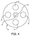
- FIG. 4 is a cross-sectional view of the multi-lumen tube of the spray applicator.
- FIG. 5 is a top view of another spray applicator.
- FIG. 6 is a plan view of the another spray applicator.
- FIG. 7 is top view of the distal end of the another spray in a substantially straight configuration.
- FIG. 8 is a top view of the distal end of the another spray applicator where the distal end is bent.
- FIG. 9 is a perspective view and a sectional view of another embodiment of the multi-lumen tube of the present invention.
- a spray applicator for applying an aerosol spray onto a surgical site is generally illustrated in FIG. 1 at 10 .
- the spray applicator 10 has a distal end that is movable to direct the aerosol spray into a selected site on or in a patient.
- the directional spray applicator 10 includes a housing 14 having parallel ports 16 , 18 and side-port 17 , the parallel ports 16 , 18 are configured for attaching to a dual chamber syringe (not shown) where the ports 16 , 18 can be utilized to transport one fluid or two fluids that are subsequently mixed together.
- the housing 14 includes passages 20 , 21 , 22 which connect to a multi-lumen tube 24 having separate lumens 26 for each of the different liquids and gases.
- the multi-lumen tube 24 also has lumens 28 for transferring a pressurized gas from the side-port 17 into a spray nozzle 30 .
- the gas can be supplied from a pressurized container via side-port 117 and passage 121 as illustrated in FIG. 6 or the gas can be supplied from a sterilized air system that is commonly available at medical treatment facilities.
- the spray nozzle is attached to a distal end 25 of the multi-lumen tube 24 .
- a swirling or tornadic activity is created which mixes the two fluids sufficiently together to form a mixture that is effective for a selected purpose, such as stopping unwanted bleeding within the surgical site.
- the pressurized gas forces the liquids from the spray nozzle 30 and onto a selected surface within a patient's body.
- the passages 20 , 22 within the housing 14 also include check valves (not shown) which prevent the gas from pressuring the liquid that are mixed together in the spray nozzle back into the syringe (not shown).
- a pre-shaped memory wire 32 such as nitinol, is positioned with a central lumen 34 within the multi-lumen tube 24 which causes a distal portion 25 of the tube 24 to have a curved configuration such that the spray nozzle 30 can be directed at different angles which allows the spray to be applied to surfaces within a surgical site.
- a typical diameter of the pre-shaped wire is 0.028 inches although other diameter wires are also contemplated.
- the pre-shaped memory wire 32 forces the distal end 25 of the multi-lumen tube 24 into a selected curved or bent configuration.
- the configuration of the distal portion 25 can be pre-determined by providing the memory wire with a pre-elected bend or curvature within the multi-lumen tube 24 .
- the multi-lumen tube 24 is typically encased within a rigid inner sheath 35 that extends from the housing 14 to proximate the distal end 25 of the tube 24 such that a segment of the multi-lumen tube 24 separates the distal end of the rigid inner sheath 35 and the spray nozzle 30 .
- the rigid inner sheath 35 maintains the encased portion of the multi-lumen tube 24 in a substantially straight configuration.
- a rigid outer sheath 36 is positioned over the rigid inner sheath 35 and has a length that is less than that of the rigid inner sheath 35 .
- the rigid outer sheath 36 slides along a length of the inner rigid sheath 35 such that when the rigid outer sheath 36 is extended toward the spray nozzle 30 , the rigidity of the outer sheath 36 straightens the pre-shaped memory wire 32 such that the spray nozzle 30 is substantially aligned with an axis 40 of the rigid inner sheath 35 .
- An external collar 37 is positioned on the rigid outer sheath 36 to provide a gripping surface for moving the rigid outer sheath 36 .
- the operator can manually move the rigid outer sheath 36 towards a proximal end 12 of the applicator 10 , thereby uncovering the distal portion 25 of the multi-lumen tube 24 .
- the memory wire 32 forces the distal portion 25 of the multi-lumen tube 24 and the spray nozzle 30 into a selected angular position.
- the outer sheath 36 can be retained in a selected position and the rigid inner sheath 35 can be further inserted into the surgical site to remove force from the distal portion 25 of the multi-lumen tube to allow the spray nozzle 30 to be positioned at a selected angular position.
- the memory wire 32 forces the distal portion 25 into another selected position based upon the shape of the memory wire 32 that is substantially perpendicular to the axis 40 of the rigid inner sheath 35 .
- the spray nozzle 30 is positioned at a more acute angle with respect to the axis 40 of the rigid inner sheath 35 .
- the inner sheath 35 also is rotatable within the outer sheath 36 , such that the spray nozzle 30 can be rotated 360° around the axis 40 to spray a larger area within the surgical site.
- a non-rotatable slidable engagement of the outer sheath 36 and the inner sheath 35 is also contemplated.
- another spray applicator 110 can also utilizes a malleable wire 132 within a multi-lumen tube 124 .
- a malleable wire is an annealed 304 stainless steel that has a 0.028 inch diameter.
- malleable is meant a wire that can be bent with manual force and retails a selected shape until a separate manual force is placed upon the wire.
- the applicator 110 includes a housing 114 having the same or similar configuration to that of housing 14 .
- the multi-lumen tube 124 is flexible and is positioned within a sheath 135 , which may be either rigid or flexible.
- a distal end 125 of the multi-lumen tube 124 extends from the sheath 135 and has a spray nozzle 130 attached to the distal end 125 as shown in FIG. 6 .
- the sheath 135 may extend to the spray nozzle 130 as shown in FIG. 5 provided the sheath 135 is flexible.
- the applicator 110 operates in a manner substantially the same as the applicator 10 . However, to position the spray nozzle 130 in a selected position, manual force is exerted upon the multi-lumen tube 124 and/or the sheath 135 to bend the malleable wire 132 .
- the malleable wire 132 retains the spray nozzle 130 in a selected position from a straight configuration in FIG. 7 to a bent or angular configuration in FIG. 8 such that a spray can be directed to a selected area in a surgical site.
- FIG. 9 Another configuration of a multi-lumen tube 224 is illustrated in FIG. 9 .
- the multi-lumen tube 224 includes arcuate cross sectional indentions 250 extending along at least a partial length of the tube 224 .
- the multi-lumen tube 224 is positioned within a sheath 135 .
- the perimeter edges 225 and an inner surface of the sheath 137 form lumens 257 and a hermetic seal between the lumens 257 to prevent cross-contamination of liquids and/or liquids and gases between the lumens 257 .
- Positioning lumens 257 at an exterior of the tube 224 prevents the cross-sectional area of the lumens 257 from being reduced as the tube 224 is bent and thereby ensures a more reliable delivery of the liquids and gases to the surgical site.
Abstract
Description
Claims (6)
Priority Applications (1)
| Application Number | Priority Date | Filing Date | Title |
|---|---|---|---|
| US12/369,069 US8303531B2 (en) | 2008-02-11 | 2009-02-11 | Spray applicator with positionable spray tip |
Applications Claiming Priority (2)
| Application Number | Priority Date | Filing Date | Title |
|---|---|---|---|
| US2755708P | 2008-02-11 | 2008-02-11 | |
| US12/369,069 US8303531B2 (en) | 2008-02-11 | 2009-02-11 | Spray applicator with positionable spray tip |
Publications (2)
| Publication Number | Publication Date |
|---|---|
| US20090199848A1 US20090199848A1 (en) | 2009-08-13 |
| US8303531B2 true US8303531B2 (en) | 2012-11-06 |
Family
ID=40937831
Family Applications (1)
| Application Number | Title | Priority Date | Filing Date |
|---|---|---|---|
| US12/369,069 Expired - Fee Related US8303531B2 (en) | 2008-02-11 | 2009-02-11 | Spray applicator with positionable spray tip |
Country Status (1)
| Country | Link |
|---|---|
| US (1) | US8303531B2 (en) |
Cited By (3)
| Publication number | Priority date | Publication date | Assignee | Title |
|---|---|---|---|---|
| WO2015176905A1 (en) | 2014-05-22 | 2015-11-26 | Medmix Systems Ag | Laparoscopic spray applicator and adapter |
| US20170216537A1 (en) * | 2014-08-15 | 2017-08-03 | Alesi Surgical Limited | Surgical spray instrument |
| US10952709B2 (en) | 2014-04-04 | 2021-03-23 | Hyperbranch Medical Technology, Inc. | Extended tip spray applicator for two-component surgical sealant, and methods of use thereof |
Families Citing this family (12)
| Publication number | Priority date | Publication date | Assignee | Title |
|---|---|---|---|---|
| US8210453B2 (en) | 2008-09-12 | 2012-07-03 | Confluent Surgical, Inc. | Spray applicator |
| CN102500019B (en) * | 2009-10-05 | 2013-08-14 | 乌日娜 | Atomization device for administration under laryngoscope |
| CH703974A1 (en) | 2010-10-15 | 2012-04-30 | Medmix Systems Ag | Medical spray head with pressure gas support. |
| WO2012145703A1 (en) * | 2011-04-20 | 2012-10-26 | Kinamed, Inc. | Shapeable passer for surgical cable or suture |
| CA2870391A1 (en) * | 2012-04-23 | 2013-10-31 | Chiesi Farmaceutici S.P.A. | Method and system for the administration of a pulmonary surfactant by atomization |
| US9174001B2 (en) | 2012-08-10 | 2015-11-03 | Nordson Corporation | Device and method for discharging a reactive liquid |
| TW201609206A (en) * | 2013-10-22 | 2016-03-16 | 奇希製藥公司 | Improved method and system for the administration of a pulmonary surfactant by atomization |
| US9101391B2 (en) | 2013-11-11 | 2015-08-11 | Cross Bay Medical, Inc. | Apparatus and methods for accessing and sealing bodily vessels and cavities |
| WO2017011539A2 (en) * | 2015-07-13 | 2017-01-19 | Cook Regentec Llc | Catheters and systems useful for delivery of material to the lung |
| EP3423133A4 (en) * | 2016-03-02 | 2019-11-06 | CrossBay Medical, Inc. | Method and apparatus of echogenic catheter systems |
| DE102018121513B4 (en) | 2018-09-04 | 2020-04-02 | Prof. Reymond & Hetzel GbR (vertretungsberechtigter Gesellschafter: Alexander Hetzel, 78667 Villingendorf) | Medical instrument for the directed introduction of a substance into a cavity of a body and tool therefor |
| CA3160029A1 (en) | 2019-10-09 | 2021-04-15 | Steven R. Bacich | Apparatus and method for everting catheter for iud delivery and placement in the uterine cavity |
Citations (7)
| Publication number | Priority date | Publication date | Assignee | Title |
|---|---|---|---|---|
| US4932942A (en) | 1987-01-09 | 1990-06-12 | Harald Maslanka | Injection equipment with a twin tubular needle for an endoscope |
| US4990140A (en) | 1989-11-13 | 1991-02-05 | Johnson & Johnson Medical, Inc. | Flexible spray tip for syringe |
| JPH05168714A (en) | 1991-12-25 | 1993-07-02 | Nissho Corp | Catheter intra-abdominally spraying medicinal liquid preparation |
| US5484408A (en) * | 1989-04-13 | 1996-01-16 | Scimed Life Systems, Inc. | Innerless catheter |
| US20050125002A1 (en) * | 2003-10-31 | 2005-06-09 | George Baran | System and method for manipulating a catheter for delivering a substance to a body cavity |
| US6974411B2 (en) | 2000-04-03 | 2005-12-13 | Neoguide Systems, Inc. | Endoscope with single step guiding apparatus |
| US7172552B2 (en) | 2000-01-27 | 2007-02-06 | Boston Scientific Scimed, Inc. | Catheter introducer system for exploration of body cavities |
-
2009
- 2009-02-11 US US12/369,069 patent/US8303531B2/en not_active Expired - Fee Related
Patent Citations (7)
| Publication number | Priority date | Publication date | Assignee | Title |
|---|---|---|---|---|
| US4932942A (en) | 1987-01-09 | 1990-06-12 | Harald Maslanka | Injection equipment with a twin tubular needle for an endoscope |
| US5484408A (en) * | 1989-04-13 | 1996-01-16 | Scimed Life Systems, Inc. | Innerless catheter |
| US4990140A (en) | 1989-11-13 | 1991-02-05 | Johnson & Johnson Medical, Inc. | Flexible spray tip for syringe |
| JPH05168714A (en) | 1991-12-25 | 1993-07-02 | Nissho Corp | Catheter intra-abdominally spraying medicinal liquid preparation |
| US7172552B2 (en) | 2000-01-27 | 2007-02-06 | Boston Scientific Scimed, Inc. | Catheter introducer system for exploration of body cavities |
| US6974411B2 (en) | 2000-04-03 | 2005-12-13 | Neoguide Systems, Inc. | Endoscope with single step guiding apparatus |
| US20050125002A1 (en) * | 2003-10-31 | 2005-06-09 | George Baran | System and method for manipulating a catheter for delivering a substance to a body cavity |
Cited By (4)
| Publication number | Priority date | Publication date | Assignee | Title |
|---|---|---|---|---|
| US10952709B2 (en) | 2014-04-04 | 2021-03-23 | Hyperbranch Medical Technology, Inc. | Extended tip spray applicator for two-component surgical sealant, and methods of use thereof |
| WO2015176905A1 (en) | 2014-05-22 | 2015-11-26 | Medmix Systems Ag | Laparoscopic spray applicator and adapter |
| US20170216537A1 (en) * | 2014-08-15 | 2017-08-03 | Alesi Surgical Limited | Surgical spray instrument |
| US10238818B2 (en) * | 2014-08-15 | 2019-03-26 | Alesi Surgical Limited | Surgical spray instrument |
Also Published As
| Publication number | Publication date |
|---|---|
| US20090199848A1 (en) | 2009-08-13 |
Similar Documents
| Publication | Publication Date | Title |
|---|---|---|
| US8303531B2 (en) | Spray applicator with positionable spray tip | |
| EP1680173B1 (en) | System for manipulating a catheter for delivering a substance to a body cavity | |
| US10456519B2 (en) | Apparatus and method for irrigating sinus cavity | |
| US8790301B2 (en) | Systems and methods for biofilm removal, including a biofilm removal endoscope for use therewith | |
| AU2009241564B2 (en) | Surgical instrument, system, and method for frontal sinus irrigation | |
| EP2770897B1 (en) | Multi-sectioned cannula with at least one lumen | |
| CN107073164A (en) | Range indicator for medicinal sprayer unit | |
| AU2016391075B2 (en) | Suction and irrigation device | |
| JP2014532476A5 (en) | ||
| EP2638969A2 (en) | Applicator spray nozzles with pressure relief | |
| JP6297494B2 (en) | Multi orifice spray head | |
| CA2966160C (en) | Fluid dispensing catheter | |
| US20220040398A1 (en) | Dual cannulated suction and delivery device | |
| KR20230066396A (en) | pharmaceutical delivery device |
Legal Events
| Date | Code | Title | Description |
|---|---|---|---|
| AS | Assignment |
Owner name: MICROMEDICS, INC., MINNESOTA Free format text: ASSIGNMENT OF ASSIGNORS INTEREST;ASSIGNOR:SHARRATT, TODD W.;REEL/FRAME:022242/0977 Effective date: 20090211 |
|
| AS | Assignment |
Owner name: NORDSON CORPORATION, OHIO Free format text: ASSIGNMENT OF ASSIGNORS INTEREST;ASSIGNOR:MICROMEDICS, INC.;REEL/FRAME:026081/0827 Effective date: 20110323 |
|
| FEPP | Fee payment procedure |
Free format text: PAYOR NUMBER ASSIGNED (ORIGINAL EVENT CODE: ASPN); ENTITY STATUS OF PATENT OWNER: LARGE ENTITY |
|
| REMI | Maintenance fee reminder mailed | ||
| LAPS | Lapse for failure to pay maintenance fees | ||
| STCH | Information on status: patent discontinuation |
Free format text: PATENT EXPIRED DUE TO NONPAYMENT OF MAINTENANCE FEES UNDER 37 CFR 1.362 |
|
| FP | Lapsed due to failure to pay maintenance fee |
Effective date: 20161106 |