US8099624B1 - Recovery mechanism for I/O module using out-of-band control path - Google Patents
Recovery mechanism for I/O module using out-of-band control path Download PDFInfo
- Publication number
- US8099624B1 US8099624B1 US12/557,441 US55744109A US8099624B1 US 8099624 B1 US8099624 B1 US 8099624B1 US 55744109 A US55744109 A US 55744109A US 8099624 B1 US8099624 B1 US 8099624B1
- Authority
- US
- United States
- Prior art keywords
- module
- data
- control command
- storage server
- storage
- Prior art date
- Legal status (The legal status is an assumption and is not a legal conclusion. Google has not performed a legal analysis and makes no representation as to the accuracy of the status listed.)
- Active, expires
Links
Images


Classifications
-
- G—PHYSICS
- G06—COMPUTING; CALCULATING OR COUNTING
- G06F—ELECTRIC DIGITAL DATA PROCESSING
- G06F11/00—Error detection; Error correction; Monitoring
- G06F11/07—Responding to the occurrence of a fault, e.g. fault tolerance
- G06F11/0703—Error or fault processing not based on redundancy, i.e. by taking additional measures to deal with the error or fault not making use of redundancy in operation, in hardware, or in data representation
- G06F11/0793—Remedial or corrective actions
-
- G—PHYSICS
- G06—COMPUTING; CALCULATING OR COUNTING
- G06F—ELECTRIC DIGITAL DATA PROCESSING
- G06F11/00—Error detection; Error correction; Monitoring
- G06F11/07—Responding to the occurrence of a fault, e.g. fault tolerance
- G06F11/0703—Error or fault processing not based on redundancy, i.e. by taking additional measures to deal with the error or fault not making use of redundancy in operation, in hardware, or in data representation
- G06F11/0706—Error or fault processing not based on redundancy, i.e. by taking additional measures to deal with the error or fault not making use of redundancy in operation, in hardware, or in data representation the processing taking place on a specific hardware platform or in a specific software environment
- G06F11/0727—Error or fault processing not based on redundancy, i.e. by taking additional measures to deal with the error or fault not making use of redundancy in operation, in hardware, or in data representation the processing taking place on a specific hardware platform or in a specific software environment in a storage system, e.g. in a DASD or network based storage system
-
- G—PHYSICS
- G06—COMPUTING; CALCULATING OR COUNTING
- G06F—ELECTRIC DIGITAL DATA PROCESSING
- G06F11/00—Error detection; Error correction; Monitoring
- G06F11/07—Responding to the occurrence of a fault, e.g. fault tolerance
- G06F11/08—Error detection or correction by redundancy in data representation, e.g. by using checking codes
- G06F11/10—Adding special bits or symbols to the coded information, e.g. parity check, casting out 9's or 11's
- G06F11/1076—Parity data used in redundant arrays of independent storages, e.g. in RAID systems
- G06F11/108—Parity data distribution in semiconductor storages, e.g. in SSD
Definitions
- This invention relates generally to recovering an I/O module in a storage system, and more particularly to improve the resiliency of the I/O module in the storage system using an out-of-band control path.
- Network-based storage systems exist today. These forms include network attached storage (NAS), storage area networks (SANs), and others.
- NAS network attached storage
- SANs storage area networks
- Network storage systems are commonly used for a variety of purposes, such as providing multiple users with access to shared data, backing up critical data (e.g., by data mirroring), and the like.
- a network-based storage system typically includes at least one storage server, which is a processing system configured to store and retrieve data on behalf of one or more client processing systems (“clients”).
- a storage server operates on behalf of one or more clients to store and manage shared files.
- the files may be stored in a storage subsystem that includes one or more arrays of mass storage devices, such as magnetic or optical disks or tapes, by using RAID (Redundant Array of Inexpensive Disks). Hence, the mass storage devices in each array may be organized into one or more separate RAID groups.
- a storage server provides clients with file-level access. Some storage servers may additionally provide block-level access.
- a client can send a request to a storage server to access data stored on disks in a storage subsystem.
- the storage server includes a storage adapter coupled to an I/O module in the storage subsystem that creates an in-band communications path, also known as a data path, to access the data stored on the disks.
- An I/O module can receive and process a request through the in-band path.
- An I/O module may be non-responsive to a request which can result in a time-out. There is not, however, a means for controlling a non-responsive I/O module independent of the in-band path.
- a storage system includes a storage server coupled to a storage subsystem having an I/O module coupled to a number of disks.
- the storage server includes a storage adapter coupled to an I/O module in the storage subsystem creating an in-band communication path, also known as a data path, to access data stored on the disks.
- the storage server sends a data command, such as a read command, to the I/O module in the storage subsystem through the in-band (data) path.
- the storage server further includes a network adapter coupled to the I/O module creating an out-of-band control path to control the I/O module.
- the storage server detects through the in-band path that the I/O module is non-responsive to the data command and automatically changes the behavior of the I/O module through the out-of-band control path to recover the non-responsive I/O module.
- the storage server sends a control command, such as a reset command, to the I/O module through the out-of-band control path to change the behavior of the I/O module (e.g., reset the I/O module) to recover the non-responsive I/O module.
- the storage server further determines through the in-band path whether the I/O module is non-responsive to the control command.
- the storage server further sends a different control command, such as a power cycle command, to the I/O module through the out-of-band control path. If the I/O module is responsive, the storage server obtains status data of the I/O module through the out-of-band control path. The storage server further outputs the I/O module status data to an administrator for analysis.
- a different control command such as a power cycle command
- FIG. 1 illustrates an embodiment of a networked storage system
- FIG. 2 illustrates another embodiment of a networked storage system
- FIG. 3 illustrates an embodiment of the hardware architecture for implementing an out-of-band control path from a storage server to an I/O module in a storage subsystem
- FIG. 4 illustrates an embodiment of a control architecture in a storage server for controlling an I/O module
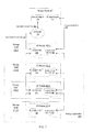
- FIG. 5 illustrates a flowchart of a method for automatically controlling an I/O module to be performed by a storage server according to one embodiment
- FIG. 6 illustrates a flowchart of a method for automatically controlling an I/O module to be performed by a storage server according to one embodiment
- FIG. 7 illustrates a flowchart of a method for automatically controlling an I/O module to be performed by a storage subsystem according to one embodiment.
- An in-band path also known as a data path, is a communications path to access data stored on disks in a storage subsystem.
- a storage server sends client requests to a storage subsystem through the in-band (data) path for accessing data stored on disks in the storage subsystem.
- the disks are coupled to an I/O module in the storage subsystem.
- the I/O module receives and processes a data request through the in-band path.
- An I/O module may be non-responsive to the request, which can result in a time-out.
- the control architecture of the present invention provides the ability to automatically change the behavior of a non-responsive I/O module to recover the non-responsive I/O module (e.g., by resetting or power cycling the non-responsive I/O module) through an out-of-band control path.
- An Out-of-Band Control Path (OOBCP) is a communications path, which is independent of the in-band (data) path, for controlling an I/O module.
- the control architecture further provides storage administrators the ability to access status data of the I/O module through the out-of-band control path for analysis.
- FIG. 1 shows a network storage system 100 according to some embodiments of the control architecture.
- FIG. 1 shows an example of a network environment in which a storage server 400 operates.
- the storage server 400 can be a file server in which the control architecture can be implemented.
- the control architecture can be applied in other types of storage systems, such as storage servers, which provide clients with either or both block-level access and file-level access to stored data, or processing systems other than storage servers, and network devices configured to provide storage services.
- the storage server 400 is coupled to a storage subsystem 200 which includes an array of mass storage devices 160 (e.g., disks), and to a set of storage client machines 110 (hereinafter simply “clients”) through a network 120 .
- the network 120 may be, for example, a local area network (LAN), a wide area network (WAN), a metropolitan area network (MAN), a wireless network, a global area network (GAN) such as the Internet, a Fibre Channel fabric, or the like, or a combination of any such types of networks.
- the network 120 can include any number of networking and computing devices such as wired and wireless devices 140 .
- Each of the clients 110 can be, for example, a conventional personal computer (PC), server-class computer, workstation, or the like.
- the storage server 400 and the storage subsystem 200 form a modular system in which one or more sets of mass storage devices 160 (disks 160 ), each in a separate chassis (“enclosure”), are connected to the storage server 400 in another chassis via network 130 .
- the network 130 can be, for example, a local area network (LAN), a wide area network (WAN), a metropolitan area network (MAN), a wireless network, a global area network (GAN) such as the Internet, a Fibre Channel fabric, or the like, or a combination of any such types of networks.
- the mass storage devices 160 in the storage subsystem 200 can be, for example, conventional magnetic disks, optical disks such as CD-ROM or DVD-based storage, magneto-optical (MO) storage, or any other type of non-volatile storage devices suitable for storing large quantities of data.
- the mass storage devices 160 are each a flash-based solid-state device (SSD), sometimes known as flash drives.
- SSD flash-based solid-state device
- the disks 160 can further be organized as a Redundant Array of Inexpensive Disks/Devices (RAID), whereby the storage server 400 accesses the disks 160 using one or more RAID protocols known in the art.
- RAID Redundant Array of Inexpensive Disks/Devices
- a storage server e.g., storage server 400
- non-volatile, solid-state NAND flash devices which are block-oriented devices having good (random) read performance, i.e., read operations to flash devices are substantially faster than write operations.
- Data stored on a flash device are accessed (e.g., via read and write operations) in units of pages, which in the present embodiment are 4 kB in size, although other page sizes (e.g., 2 kB) may also be used.
- the data is stored as stripes of blocks within the parity groups, wherein a stripe may constitute similarly located flash pages across the flash devices. For example, a stripe may span a first page 0 on flash device 0, a second page 0 on flash device 1, etc. across the entire parity group with parity being distributed among the pages of the devices.
- RAID group arrangements are possible, such as providing a RAID scheme wherein every predetermined (e.g., 8th) block in a file is a parity block.
- the enclosures for the disks 160 are herein referred to as “shelves,” “storage shelf,” or “storage shelves.”
- the storage server 400 is coupled to a number of the external storage shelves 210 - 1 to 210 - 3 .
- Each storage shelf 210 - 1 to 210 - 3 contains multiple disks 160 operated under control of the storage server 400 according to RAID protocols and includes at least one I/O module 450 - 1 A.
- the storage shelf 210 - 1 includes two I/O modules 450 - 1 A and 450 - 1 B.
- I/O module 450 - 1 B is a partner module to I/O module 450 - 1 A and I/O module 450 - 1 A is a partner module to I/O module 450 - 1 B.
- An I/O module 450 - 1 A, 450 - 1 B serves as a communications interface between the storage server 400 and the disks 160 in the storage shelf 210 - 1 .
- the disks 160 in the storage shelf 210 - 1 can be connected to the I/O module 450 - 1 by a standard Fibre Channel connection.
- the storage subsystem 200 is managed by the storage server 400 .
- the storage server 400 receives and responds to various read and write requests from the clients 110 , that are directed to data stored in, or to be stored in, the mass storage devices 160 in the storage subsystem 200 .
- the storage server 400 includes a storage adapter 403 coupled to the I/O modules 450 - 1 A, 450 - 1 B in the storage subsystem 200 creating an in-band (data) path 440 to access the data stored in, or to be stored in, the mass storage devices 160 .
- the storage adapter 403 is coupled to in-band (data) path hardware 480 on the I/O modules 450 - 1 A, 450 - 1 B to create the in-band path 440 .
- the storage server 400 also includes a network adapter 405 coupled to out-of-band control path (OOBCP) hardware 430 on the I/O modules 450 - 1 A, 450 - 1 B creating an out-of-band control path 425 to control the I/O modules 450 - 1 A, 450 - 1 B and to access status data (not shown) of the I/O modules 450 - 1 A, 450 - 1 B.
- OOBCP out-of-band control path
- the storage server 400 outputs I/O module status data to one or more clients 110 and wireless devices 140 .
- the storage server 400 also outputs I/O module status data to an output device 150 A,B (e.g., display unit, printer) coupled to the storage server 400 .
- the storage server 400 is locally coupled to an output device 150 A or communicates to an output device 150 B via network 120 .
- the storage server 400 can also be coupled through a switching fabric to other similar storage servers (not shown), which have their own local storage subsystems. In this way, all of the storage subsystems 200 can form a single storage pool, to which any client of any of the storage servers has access.
- FIG. 2 shows a simple networked storage system configuration characterized by a storage server 400 coupled to four external storage shelves 210 - 1 to 210 - 4 , illustratively, in a loop topology via network 130 .
- FC-AL Fibre Channel-Arbitrated Loop
- SAS Serial Attached Small Computer System Interface
- iSCSI Internet Small Computers Systems Interface
- each of the storage shelves 210 - 1 to 210 - 4 has the same construction.
- Each storage shelf 210 - 1 to 210 - 4 includes multiple disks and at least one I/O module 450 - 1 , which is connected between two adjacent storage shelves in the loop, or, depending on where the shelf is placed in the loop, is connected between an adjacent storage shelf 210 - 1 and the storage server 400 .
- I/O module 450 - 2 is connected between storage shelf 210 - 1 and storage shelf 210 - 3
- I/O module 450 - 1 is connected between storage shelf 210 - 2 and storage server 400 .
- each storage shelf 210 - 1 to 210 - 4 includes two I/O modules, such as I/O module 450 - 1 A in FIG. 1 and its partner I/O module 450 - 1 B.
- the storage server 400 includes a storage adapter 403 coupled to, for example, I/O module 450 - 1 in the storage subsystem 200 creating an in-band path 440 to access the data stored in the mass storage devices in storage shelf 210 - 1 .
- the storage adapter 403 couples to in-band (data) path hardware 480 on I/O module 450 - 1 to create the in-band path 440 .
- the in-band path 440 can be created using Serial Attached SCSI (SAS) cables.
- SAS Serial Attached SCSI
- the in-band path hardware 480 on storage shelf 210 - 1 can further be coupled to in-band path hardware 480 on another storage shelf 210 - 2 .
- the network adapter 405 on storage server 400 is coupled to OOBCP hardware 430 on I/O module 450 - 1 creating an out-of-band control path 425 to control the I/O module 450 - 1 and to access status data of the I/O module 450 - 1 .
- the OOBCP hardware 430 on the I/O module 450 - 1 can further be coupled to OOBCP hardware 430 on another storage shelf 210 - 2 .
- the network cabling (e.g., Ethernet cables) coupling the I/O modules and storage server 400 creates a complete network (e.g., Ethernet network) independent of the in-band path 440 . This independent network creates the out-of-band control path 425 for automatically controlling the I/O modules 450 - 1 to 450 - 4 .
- FIG. 3 is a high-level block diagram showing an example of the architecture for a storage server which implements an out-of-band control path mechanism for controlling an I/O module on a storage subsystem in a network storage system.
- the storage server includes one or more processors 310 and memory 315 connected via an interconnect 340 .
- Interconnect 340 represents any one or more separate physical buses, point to point connections, or both connected by appropriate bridges, adapters, or controllers.
- Interconnect 340 may include, for example, a system bus, a Peripheral Component Interconnect (PCI) bus, a HyperTransport or industry standard architecture (ISA) bus, a small computer system interface (SCSI) bus, a universal serial bus (USB), IIC (I2C) bus, or an Institute of Electrical and Electronics Engineers (IEEE) standard 1394 bus, sometimes referred to as “Firewire.”
- PCI Peripheral Component Interconnect
- ISA HyperTransport or industry standard architecture
- SCSI small computer system interface
- USB universal serial bus
- I2C IIC
- IEEE Institute of Electrical and Electronics Engineers
- Processor(s) 310 may include central processing units (CPUs) of storage server 400 and thus controls the overall operations of storage server 400 . In certain embodiments, processor(s) 310 accomplish this by executing firmware or software stored in memory 315 . Processor(s) 310 may be, or may include, one or more programmable general-purpose or special-purpose microprocessors, digital signal processors (DSPs), programmable controllers, application specific integrated circuits (ASICs), programmable logic devices (PLDs), or the like, or a combination of such devices.
- DSPs digital signal processors
- ASICs application specific integrated circuits
- PLDs programmable logic devices
- Memory 315 is, or includes, the main memory of storage server 400 .
- Memory 315 represents any form of random access memory (RAM), read-only memory (ROM), or the like.
- memory 315 may contain a set of computer-executed instructions which, when executed by processor(s) 310 , causes processor(s) 310 to perform operations to implement aspects of the present invention.
- the out-of-band control path mechanism resides in memory 315 enabling storage server 400 to control an I/O module through an out-of-band control path as further discussed herein.
- the out-of-band control mechanism may be implemented in computer-executable software, firmware, hardware or some combination thereof, and is discussed further in reference to FIG. 4 .
- Network adapter 327 communicates with remote devices, such as clients 110 over network 120 of FIG. 1 , to receive data access requests from the remote devices.
- Storage adapter 403 creates an in-band (data) path to a storage subsystem and allows processor(s) 310 to access mass storage devices (e.g., disks 160 in FIG. 1 ) in the storage subsystem.
- the storage adapter 403 can be, for example, a Fibre Channel adapter a SCSI adapter, for servicing client requests received via network adapter 327 .
- Network adapter 405 connects to processor(s) 310 through interconnect 340 .
- Network adapter 405 creates an out-of-band control path to a storage subsystem and provides the storage server the ability to communicate with I/O modules in the storage subsystem, such as I/O modules 450 - 1 to 450 - 4 in FIG. 2 .
- the network adapter 405 can be, for example, an Ethernet adapter or Fibre Channel adapter.
- the storage server may have a distributed architecture.
- the storage server may include a separate N-(“network”) module (not shown) and D-(“data”) module (not shown).
- the N-module is used to communicate with remote devices, such as clients 110 over network 120 of FIG. 1
- the D-module includes the file system functionality and is used to communicate with an associated storage subsystem.
- the N-module and D-module can communicate with each other using an internal protocol.
- One embodiment of this invention can be operative in that the D-module is coupled to an I/O module, such as I/O module 450 - 1 A in FIG.
- the Out-of-band Control Path Administrator e.g., OOBCPA 420 in FIG. 4 described in greater detail below
- the storage server can have an integrated architecture, where the network and data components are all contained in a single box, for example, as illustrated in FIG. 3 .
- FIG. 4 shows the administration of an out-of-band control path 425 implemented in a storage server 400 and the execution of control commands through the out-of-band control path 425 in storage subsystem 200 according to one embodiment.
- Storage server 400 illustrates an example of the storage operating system 401 for controlling the operations of the storage server 400 .
- the storage server 400 is a storage server product of NetApp, Inc., Sunnyvale, Calif., that uses the NetApp® Data ONTAPTM storage operating system.
- the storage operating system 401 and its constituent elements are preferably implemented in the form of software. However, in some embodiments, some or all of the elements of the operating system 401 may be implemented in the form of hardware (e.g., specially designed circuitry), or as a combination of hardware and software.
- the storage operating system 401 includes several modules, or “layers.”
- the storage operating system 401 includes a host bus adapter (HBA) layer 409 , and a SCSI Enclosure Service (SES) layer 407 that enables the storage server 400 to communicate with the storage shelf 210 - 1 for processing a client-initiated data command, such as a read or write request.
- the SES layer 407 tracks which I/O modules are coupled to the storage adapter 403 in the storage server 400 .
- the HBA layer 409 is the interface that passes data commands (e.g., read command, write command) from the storage server 400 to an I/O module 450 - 1 .
- the HBA layer 409 passes data commands through the storage adapter 403 .
- the HBA layer 409 receives a request from a client, such as client 110 in FIG. 1 , to access data stored on disks, such as disks 160 in FIG. 1 .
- the HBA layer 409 includes a command initiator 413 to send a data command to a data processor 465 on the I/O module 450 - 1 through in-band path 440 .
- the HBA layer 409 further includes an error detector 411 to detect whether the I/O module 450 - 1 is non-responsive to the data command sent by the command initiator 413 .
- the command initiator 413 and the error detector 411 can be implemented as hardware, computer-implemented software, firmware or a combination thereof.
- the command initiator 413 and the error detector 411 comprise instructions stored in memory 315 that cause processor 310 in FIG. 3 to perform the functions of the command initiator 413 and the error detector 411 .
- the storage server 400 includes an out-of-band control path administrator (“OOBCPA”) 420 to automatically recover the I/O module 450 - 1 .
- the OOBCPA 420 interfaces with the SES layer 407 and the HBA layer 409 of the operating system 401 .
- the error detector 411 of the HBA layer 409 sends a signal to the OOBCPA 420 indicating that an error has occurred (e.g., a timeout) and that an I/O module 450 - 1 is non-responsive to a data command.
- the signal includes data identifying the non-responsive I/O module.
- the command initiator 413 of the HBA layer 409 sends a control command to the OOBCPA 420 causing the data processor 460 on the identified I/O module 450 - 1 to change the behavior of the I/O module 450 - 1 in an attempt to recover the non-responsive I/O module.
- the command initiator 413 sends a reset command to the OOBCPA 420 causing the data processor 465 to reset the I/O module 450 - 1 .
- the command initiator 413 sends a power cycle command to the OOBCPA 420 causing the data processor 465 to power cycle the I/O module 450 - 1 .
- Each I/O module 450 - 1 includes a switch 431 coupling the I/O module 450 - 1 in the storage subsystem 200 to a network adapter 405 in the storage server 400 .
- the switch 431 is an Ethernet switch on-board the I/O module 450 - 1 .
- the switch 431 is coupled to the storage server 400 via Ethernet cabling creating an out-of-band control path 425 .
- the switch 431 uses networking technology other than Ethernet (e.g., fiber channel) to create a network coupling OOBCP processors (e.g., OOBCP processor 433 ) to the storage server 400 independent of the network coupling data processors (e.g., data processor 465 ) to the storage server 400 .
- the switch 431 can have an input port 410 -A and an output port 410 -B. In still other embodiments, the switch 431 can have more than two ports.
- the output port 410 -B is coupled to an input port on a switch of another I/O module (e.g., I/O module 450 - 2 on storage shelf 210 - 2 in FIG. 2 ).
- the input port 410 -A is coupled to a network adapter 405 in the storage server 400 .
- the OOBCPA 420 maintains data of all of the OOBCP processors coupled to the storage server 400 (e.g., OOBCP processors in storage shelves 210 - 1 to 210 - 4 in FIG. 2 ).
- the OOBCPA 420 maintains data 419 that maps each OOBCP processor to a corresponding port on an I/O module 450 - 1 .
- OOBCP processor 433 corresponds to port 1 ( 410 -A) on I/O module 450 - 1 .
- the mapping data 419 can be in the form of a mapping table, such as a routing table. In one embodiment, the mapping data 419 is stored in memory 315 on the storage server 400 .
- the OOBCP processor identifier 417 accesses the mapping data 419 to determine the port corresponding to the OOBCP processor on the non-responsive I/O module.
- the control command sender 415 sends a control command, such as a reset command, to the corresponding port 1 ( 410 -A) on the identified I/O module 450 - 1 through the out-of-band control path 425 .
- the OOBCP processor identifier 417 and the control command sender 415 can be implemented as hardware, computer-implemented software, firmware or a combination thereof.
- the OOBCP processor identifier 417 and the control command sender 415 comprise instructions stored in memory 315 that cause processor 310 in FIG. 3 to perform the functions of the OOBCP processor identifier 417 and the control command sender 415 .
- an I/O module 450 - 1 includes out-of-band control path (OOBCP) hardware 430 for controlling the I/O module 450 - 1 and in-band path hardware 480 for accessing data stored on disks (not shown) coupled to data processor 465 .
- the in-band path hardware 480 includes a data Complex Programmable Logic Device (data CPLD) 461 , data processor 465 , and memory 467 .
- the out-of-band control path hardware 430 includes a switch 431 , OOBCP processor 433 , and an OOBCP CPLD 435 .
- the input port 410 -A on the switch 431 receives a control command from the storage server 400 through the out-of-band control path 425 .
- the OOBCP processor 433 obtains the control command from the switch 431 and causes the data processor 465 to execute the control command for changing the behavior of the I/O module 450 - 1 , such as causing the I/O module to reset or power cycle.
- the OOBCP processor 433 causes the data processor 465 to change the behavior (e.g., reset, power cycle) of the I/O module 450 - 1 through the OOBCP CPLD 435 and the data CPLD 461 .
- the OOBCP CPLD 435 and the data CPLD 461 contain programmable logic to implement a specific design feature.
- the OOBCP CPLD 435 includes bit map memory 441 for programming the OOBCP CPLD 435 .
- the data CPLD 461 also includes bit map memory 463 for programming the data CPLD 461 .
- the OOBCP processor 433 programs the OOBCP CPLD 435 to program the data CPLD 461 .
- the OOBCP processor 433 programs the OOBCP CPLD 435 by setting one or more bits in the bit map memory 441 of the OOBCP CPLD 435 .
- the OOBCP CPLD 435 programs the data CPLD 461 to cause the data processor 465 to execute the control command.
- the OOBCP CPLD 435 programs the data CPLD 461 by setting one or more bits in the bit map memory 463 of the data CPLD 461 .
- control command may be a reset command and the OOBCP CPLD 435 sets one or more bits in bit map memory 463 programming the data CPLD 461 to cause the data processor 465 to reset the I/O module 450 - 1 .
- control command may be a power cycle command.
- the OOBCP CPLD 435 programs the data CPLD 461 to cause the data processor 465 to power cycle the I/O module 450 - 1 .
- the OOBCP hardware 430 includes memory 437 coupled to the OOBCP processor 433 to store data.
- the memory 437 stores status data 439 of the I/O module.
- the I/O module status data 439 includes post-data stored in the memory 437 after the behavior of the I/O module has been changed (e.g., the I/O module has been reset or power cycled). Examples of I/O module status data 439 include connection data, I/O module firmware version data, I/O module logs, voltage status data, I/O module core dump data, and SAS address data. In other embodiments, the I/O module status data can include less or more types of data.
- the in-band path hardware 480 includes memory 467 coupled to the data processor 465 to store data associated with the data processor 465 and data associated with the disks (e.g., disks 160 in FIG. 1 ) coupled to the data processor 465 .
- FIG. 5 illustrates a flowchart for a method 500 for automatically controlling an I/O module to be performed by a storage server, such as storage server 400 , according to one embodiment.
- controlling an I/O module include changing the behavior of an I/O module, such as resetting an I/O module, power cycling an I/O module, and obtaining status data of the I/O module.
- the method 500 sends a data command, such as a read command, to an I/O module in a storage subsystem to access data stored in disks.
- the method detects through an in-band path coupling the storage server to the I/O module that the I/O module is non-responsive to the data command.
- the method 500 detects that the I/O module is non-responsive to a data command by starting a time-out window when the data command is sent and detecting that no response was received from the I/O module during the time-out window.
- the method 500 detects that the I/O module is non-response to a data command by receiving an error message from the I/O module, such as an SMP error, SES error, or a drive error.
- the method 500 sends a control command through an out-of-band control path coupling the storage server to the I/O module, which is independent of the in-band path, to change the behavior of the I/O module.
- the method sends a reset command through the out-of-band control path to reset the I/O module.
- the method 500 stores data indicating that the control command was sent to the I/O module and what type of control command was sent to the I/O module.
- the data can be stored in memory, for example, memory 315 on the storage server 400 in FIG. 3 .
- FIG. 6 describes one embodiment of the storage server sending a control command through the out-of-band control path in greater detail below.
- the method determines whether the I/O module is responsive to the method 500 sending the control command (at block 505 ). If the I/O module is responsive, the method 500 obtains status data of the I/O module from the I/O module through the out-of-band control path at block 509 . The method queries an OOBCP processor on the I/O module for the status data stored in the memory coupled to the OOBCP processor.
- the I/O module status data includes post-data stored in the memory after the I/O module has been reset, such as connection data, I/O module firmware version data, I/O module logs, voltage status data, I/O module core dump data, and SAS address data.
- the I/O module status data can include less or more types of data.
- the method 500 sends the I/O module status data obtained from the memory on the I/O module to a device and the method completes.
- the storage server outputs the I/O module status data to an external device (e.g., a printer, a display, a computer, a wireless device, a PDA, etc.) accessible to a user (e.g., an administrator).
- a user e.g., an administrator
- a user can use the I/O module status data to analyze one or more I/O modules.
- the method 500 if the I/O module is still non-response (block 507 ) to the method 500 sending the control command (at block 505 ), the method 500 continues to block 513 to send a different control command through the OOBCP, such as a power cycle command that causes the I/O module to perform a hard reset.
- the method 500 stores data indicating that a different control command was sent to the I/O module and what type of different control command was sent to the I/O module.
- the data can be stored in memory, for example, memory 315 on the storage server 400 in FIG. 3 .
- the method 500 determines whether the I/O module is responsive to the different control command.
- the method 500 marks the I/O module as inoperative at block 517 , and the method completes. If the I/O module is responsive after sending the different control command at block 515 , the method obtains status data of the I/O module from the I/O module through the out-of-band control path at block 509 . At block 511 , the method 500 sends the I/O module status data obtained from the memory on the I/O module to a device and the method completes.
- the method issues a control command to change the behavior of (e.g., reset or power cycle) other I/O modules in the same domain as the non-responsive I/O module.
- the method 500 changes the behavior (e.g., reset, power cycle) of multiple I/O modules in the same domain to recover non-responsive I/O modules.
- a domain is a number of I/O modules that are coupled to the same storage adapter in an in-band path, such as storage adapter 403 in FIG. 4 .
- the method detects through the in-band path that a number of I/O modules are non-responsive to data commands. For example, the method detects that an error, such as an SMP error, SES error, or a drive error, has occurred on multiple I/O modules in the same domain and resets or power cycles the I/O modules that are in the domain.
- an error such as an SMP error, SES error, or a drive error
- FIG. 6 illustrates a flowchart for a method 600 for automatically controlling an I/O module to be performed by a storage server, such as storage server 400 , according to one embodiment.
- the method 600 obtains a Media Access Control (MAC) address of an OOBCP processor on each I/O module coupled to the storage server.
- MAC Media Access Control
- the I/O module sends the MAC address of its OOBCP processor to the storage server.
- the I/O module such as I/O module 450 - 1 A in FIG. 1
- a partner I/O module such as I/O module 450 - 1 B in FIG.
- the I/O module 450 - 1 A also sends the MAC address of the OOBCP processor of the partner I/O module 450 - 1 B.
- the MAC address data for each OOBCP processor coupled to the storage server is stored.
- the MAC address data is stored as a mapping table (routing table) in memory on the storage server.
- the SES layer of the storage server tracks the MAC address data.
- the method 600 determines an Internet Protocol (IP) address for each port on a switch on each I/O module coupled to the storage server.
- IP Internet Protocol
- the method monitors for incoming packet traffic from the ports. For example, the method sends a multicast packet requesting, from all of the I/O modules on the network, the IP address of each port. Each port sends a packet to the storage server including the IP address of the port and the MAC address of the OOBCP processor on the I/O module.
- the method 600 receives a packet from a port and checks the mapping table (MAC address table) stored at block 603 , to determine if the MAC address table contains the MAC address of the OOBCP processor in the received packet.
- mapping table MAC address table
- the method 600 ignores the packet. If the MAC address table does not contain the MAC address of the OOBCP processor, the method assigns the IP address in the received packet to the MAC address of the OOBCP processor in the MAC address table. At block 607 , the method 600 stores the assignment in the MAC address table to track that the IP address of this particular port on the I/O module corresponds to the MAC address of this particular OOBCP processor.
- the method 600 replaces the IP address already stored in the MAC address table with the IP address in the received packet if the IP address in the packet does not conflict with any IP address in the MAC address table.
- a port sends a packet to the storage server including a MAC address, a null IP address (e.g., IP address 0.0.0.0), and a flag in the packet that is set to indicate the IP address is to be assigned.
- the storage server assigns an IP address that is not being used and stores the assignment in the MAC address table at block 607 .
- the method 600 sends a data command, such as a read command, through an in-band path coupling the storage server to an I/O module to access data stored in disks coupled to the I/O module.
- a data command such as a read command
- the method detects through the in-band path that the I/O module is non-responsive to the data command. For example, the method encounters an SMP error, SES error, or a drive error to detect the I/O module is non-responsive to a data command.
- the method determines from the error message the MAC address of the OOBCP processor on the I/O module that is non-responsive.
- the method 600 determines the IP address of a port on the I/O module that corresponds to the MAC address by accessing the mapping table (MAC address table).
- the method sends a control command (e.g., a reset command, power cycle command) changing the behavior of the I/O module through an out-of-band control path coupling the storage server to the I/O module to recover the I/O module and the method completes.
- the method 600 changes the behavior of (e.g., resets or power cycles) multiple I/O modules that are in the same domain as the non-responsive I/O module to recover the non-responsive I/O module.
- FIG. 7 illustrates a flowchart for a method 700 for automatically controlling an I/O module to be performed by a storage subsystem, such as storage subsystem 200 , according to one embodiment.
- the method receives a control command, such as a reset command, from a storage server through an out-of-band control path.
- a control command such as a reset command
- a port on an I/O module in a storage shelf in the storage subsystem receives the control command.
- the method 700 determines whether the control command is addressed to the port receiving the control command.
- the control command includes the destination IP address of the destination port and information of the command type. For example, the information can indicate the command is a reset command or a power cycle command.
- the method determines whether the destination IP address included in the control command matches the IP address of the port receiving the control command. If the destination IP address does not match the IP address of the port receiving the command, the method 700 forwards the control command through an output port to another I/O module at block 705 , and the method finishes. For example, an input port on an I/O module, such as I/O module 450 - 3 in FIG. 2 , receives a signal (e.g., a reset command) addressed to an input port on another I/O module, such as I/O module 450 - 4 in FIG. 2 .
- a signal e.g., a reset command
- the method determines that the destination address in the reset command does not match the IP address of the port on I/O module 450 - 3 , and the method forwards the reset command through an output port on I/O module 450 - 3 to be received by an input port on I/O module 450 - 4 .
- the input port on I/O module 450 - 4 receives the reset command and determines that the destination IP address in the reset command matches its IP address.
- the signal can pass through a number of input ports and output ports on a number of I/O modules until the signal is received by the input port having an IP address that matches the destination IP address in the control command.
- the method 700 causes the command to execute at block 707 .
- an input port of a switch on an I/O module receives a reset command having a destination IP address that matches the IP address of the input port that receives the control command.
- the OOBCP processor on the I/O module obtains the reset command from the switch and programs an OOBCP CPLD to program a data CPLD on the I/O module.
- the OOBCP processor programs the OOBCP CPLD by setting one or more bits in the bit map memory of the OOBCP CPLD.
- the OOBCP CPLD programs the data CPLD to cause a data processor on the I/O module to execute the reset command.
- the OOBCP CPLD programs the data CPLD by setting one or more bits in the bit map memory of the data CPLD.
- the control command may be a power cycle command.
- the OOBCP CPLD programs the data CPLD to cause the data processor to power cycle the I/O module.
- the method 700 collects status data of the I/O module.
- I/O module status data include connection data, I/O module firmware version data, I/O module logs, voltage status data, I/O module core dump data, and SAS address data.
- the I/O module status data can include less or more types of data.
- the method stores the I/O module status data. In one embodiment, the method stores the status data in memory in the I/O module coupled to an OOBCP processor in the I/O module.
- the method 700 determines whether it receives a query through the out-of-band control path for the I/O module status data from, for example, the storage server.
- the method finishes. If the method receives a query for the status data, the method 700 sends the I/O module status data through the out-of-band control path to the storage server at block 715 and the method finishes.
- the methods 500 , 600 , and 700 can constitute one or more programs made up of computer-executable instructions. Describing the method with reference to the flowcharts in FIGS. 5-7 enables one skilled in the art to develop such programs, including such instructions to carry out the operations (acts) represented by logical blocks 500 until 517 , 600 until 617 , and 700 until 715 on suitably configured computers (the processor of the computer executing the instructions from computer-readable media).
- the computer-executable instructions can be written in a computer programming language or can be embodied in firmware logic or in hardware circuitry. If written in a programming language conforming to a recognized standard, such instructions can be executed on a variety of hardware platforms and for interface to a variety of operating systems.
- FIGS. 1-4 are intended to provide an overview of computer hardware and other operating components suitable for performing the methods of the invention described above, but is not intended to limit the applicable environments.
- One of skill in the art will immediately appreciate that the invention can be practiced with other computer system configurations.
- the invention can also be practiced in distributed computing environments where tasks are performed by remote processing devices that are linked through a communications network.
- memory as used herein is intended to encompass all volatile storage media, such as dynamic random access memory (DRAM) and static RAM (SRAM).
- Computer-executable instructions can be stored on non-volatile storage devices, such as magnetic hard disk, an optical disk, and are typically written, by a direct memory access process, into memory during execution of software by a processor.
- non-volatile storage devices such as magnetic hard disk, an optical disk, and are typically written, by a direct memory access process, into memory during execution of software by a processor.
- computer-readable storage medium includes any type of volatile or non-volatile storage device that is accessible by a processor.
Abstract
Description
Claims (24)
Priority Applications (1)
| Application Number | Priority Date | Filing Date | Title |
|---|---|---|---|
| US12/557,441 US8099624B1 (en) | 2009-09-10 | 2009-09-10 | Recovery mechanism for I/O module using out-of-band control path |
Applications Claiming Priority (1)
| Application Number | Priority Date | Filing Date | Title |
|---|---|---|---|
| US12/557,441 US8099624B1 (en) | 2009-09-10 | 2009-09-10 | Recovery mechanism for I/O module using out-of-band control path |
Publications (1)
| Publication Number | Publication Date |
|---|---|
| US8099624B1 true US8099624B1 (en) | 2012-01-17 |
Family
ID=45445185
Family Applications (1)
| Application Number | Title | Priority Date | Filing Date |
|---|---|---|---|
| US12/557,441 Active 2030-01-01 US8099624B1 (en) | 2009-09-10 | 2009-09-10 | Recovery mechanism for I/O module using out-of-band control path |
Country Status (1)
| Country | Link |
|---|---|
| US (1) | US8099624B1 (en) |
Cited By (16)
| Publication number | Priority date | Publication date | Assignee | Title |
|---|---|---|---|---|
| US20140019646A1 (en) * | 2012-07-12 | 2014-01-16 | International Business Machines Corporation | Service Channel For Connecting A Host Computer To Peripheral Devices |
| US20140082236A1 (en) * | 2012-09-14 | 2014-03-20 | Weijia Zhang | Systems and methods for intelligent system profile unique data management |
| US8832369B2 (en) | 2010-10-27 | 2014-09-09 | Dell Products, Lp | Systems and methods for remote raid configuration in an embedded environment |
| US8966026B2 (en) | 2009-09-30 | 2015-02-24 | Dell Products Lp | Systems and methods for extension of server management functions |
| US20150074250A1 (en) * | 2012-04-25 | 2015-03-12 | Jichuan Chang | Network management |
| WO2015112564A1 (en) * | 2014-01-21 | 2015-07-30 | Netapp, Inc. | In-band recovery mechanism for i/o modules in a data storage system |
| US9146812B2 (en) | 2012-02-03 | 2015-09-29 | Dell Products Lp | Systems and methods for out-of-band backup and restore of hardware profile information |
| US9280410B2 (en) | 2007-05-11 | 2016-03-08 | Kip Cr P1 Lp | Method and system for non-intrusive monitoring of library components |
| US9304700B2 (en) | 2013-04-18 | 2016-04-05 | Netapp, Inc. | Method and system for remotely controlling a storage shelf of a storage system |
| US9317358B2 (en) | 2009-12-16 | 2016-04-19 | Kip Cr P1 Lp | System and method for archive verification according to policies |
| US20170111238A1 (en) * | 2015-10-20 | 2017-04-20 | Hong Fu Jin Precision Industry (Shenzhen) Co., Ltd. | Management device |
| US9699056B2 (en) | 2008-02-04 | 2017-07-04 | Kip Cr P1 Lp | System and method of network diagnosis |
| US9866633B1 (en) * | 2009-09-25 | 2018-01-09 | Kip Cr P1 Lp | System and method for eliminating performance impact of information collection from media drives |
| US10379949B2 (en) | 2017-09-29 | 2019-08-13 | Apple Inc. | Techniques for managing parity information for data stored on a storage device |
| US11221786B2 (en) * | 2020-03-30 | 2022-01-11 | EMC IP Holding Company LLC | Fast recovery in recoverpoint using direct storage access |
| US20220374377A1 (en) * | 2021-05-20 | 2022-11-24 | Nordic Semiconductor Asa | Bus decoder |
Citations (18)
| Publication number | Priority date | Publication date | Assignee | Title |
|---|---|---|---|---|
| US5835566A (en) * | 1996-03-29 | 1998-11-10 | Telecom Technologies, Inc. | System and method for providing in-band and out-of-band testing of telecommunications network components |
| US5983366A (en) * | 1997-03-19 | 1999-11-09 | Optimay Corporation | Data processing system having monitoring of software activity |
| US6163815A (en) * | 1998-05-27 | 2000-12-19 | International Business Machines Corporation | Dynamic disablement of a transaction ordering in response to an error |
| US6263452B1 (en) * | 1989-12-22 | 2001-07-17 | Compaq Computer Corporation | Fault-tolerant computer system with online recovery and reintegration of redundant components |
| US20010039639A1 (en) * | 2000-03-27 | 2001-11-08 | Hiroshi Hama | Error detection and correction circuit |
| US6330690B1 (en) * | 1997-05-13 | 2001-12-11 | Micron Electronics, Inc. | Method of resetting a server |
| US20030229839A1 (en) * | 2002-06-08 | 2003-12-11 | Axiowave Networks, Inc. | Method of and apparatus for protecting against and correcting errors in data packet flow streams in closed ring sequential address generators and the like and in other data pack flow paths, without data flow stream interruption |
| US20050005196A1 (en) * | 2003-06-13 | 2005-01-06 | Evolium S.A.S. | Method of improving the interface efficiency in a communications network |
| US20050039070A1 (en) * | 2003-08-13 | 2005-02-17 | International Business Machines Corporation | System and method for analysis and filtering of signals in a telecommunications network |
| US20050278563A1 (en) * | 2004-06-09 | 2005-12-15 | Durham David M | Notifying remote administrator of platform integrity determination |
| US6983362B1 (en) * | 2000-05-20 | 2006-01-03 | Ciena Corporation | Configurable fault recovery policy for a computer system |
| US7155722B1 (en) * | 2001-07-10 | 2006-12-26 | Cisco Technology, Inc. | System and method for process load balancing in a multi-processor environment |
| US20080052394A1 (en) * | 2006-08-22 | 2008-02-28 | Bugenhagen Michael K | System and method for initiating diagnostics on a packet network node |
| US7401254B2 (en) * | 2003-04-23 | 2008-07-15 | Dot Hill Systems Corporation | Apparatus and method for a server deterministically killing a redundant server integrated within the same network storage appliance chassis |
| US20090201805A1 (en) * | 2008-02-10 | 2009-08-13 | Cisco Technology Inc. | Forward error correction based data recovery with path diversity |
| US7590892B2 (en) * | 2005-05-16 | 2009-09-15 | Texas Instruments Incorporated | Method and system of profiling real-time streaming channels |
| US7660913B2 (en) * | 2005-04-20 | 2010-02-09 | Intel Corporation | Out-of-band platform recovery |
| US7688796B2 (en) * | 2005-08-31 | 2010-03-30 | Interdigital Technology Corporation | Wireless communication method and apparatus for decoding enhanced dedicated channel absolute grant channel transmissions |
-
2009
- 2009-09-10 US US12/557,441 patent/US8099624B1/en active Active
Patent Citations (18)
| Publication number | Priority date | Publication date | Assignee | Title |
|---|---|---|---|---|
| US6263452B1 (en) * | 1989-12-22 | 2001-07-17 | Compaq Computer Corporation | Fault-tolerant computer system with online recovery and reintegration of redundant components |
| US5835566A (en) * | 1996-03-29 | 1998-11-10 | Telecom Technologies, Inc. | System and method for providing in-band and out-of-band testing of telecommunications network components |
| US5983366A (en) * | 1997-03-19 | 1999-11-09 | Optimay Corporation | Data processing system having monitoring of software activity |
| US6330690B1 (en) * | 1997-05-13 | 2001-12-11 | Micron Electronics, Inc. | Method of resetting a server |
| US6163815A (en) * | 1998-05-27 | 2000-12-19 | International Business Machines Corporation | Dynamic disablement of a transaction ordering in response to an error |
| US20010039639A1 (en) * | 2000-03-27 | 2001-11-08 | Hiroshi Hama | Error detection and correction circuit |
| US6983362B1 (en) * | 2000-05-20 | 2006-01-03 | Ciena Corporation | Configurable fault recovery policy for a computer system |
| US7155722B1 (en) * | 2001-07-10 | 2006-12-26 | Cisco Technology, Inc. | System and method for process load balancing in a multi-processor environment |
| US20030229839A1 (en) * | 2002-06-08 | 2003-12-11 | Axiowave Networks, Inc. | Method of and apparatus for protecting against and correcting errors in data packet flow streams in closed ring sequential address generators and the like and in other data pack flow paths, without data flow stream interruption |
| US7401254B2 (en) * | 2003-04-23 | 2008-07-15 | Dot Hill Systems Corporation | Apparatus and method for a server deterministically killing a redundant server integrated within the same network storage appliance chassis |
| US20050005196A1 (en) * | 2003-06-13 | 2005-01-06 | Evolium S.A.S. | Method of improving the interface efficiency in a communications network |
| US20050039070A1 (en) * | 2003-08-13 | 2005-02-17 | International Business Machines Corporation | System and method for analysis and filtering of signals in a telecommunications network |
| US20050278563A1 (en) * | 2004-06-09 | 2005-12-15 | Durham David M | Notifying remote administrator of platform integrity determination |
| US7660913B2 (en) * | 2005-04-20 | 2010-02-09 | Intel Corporation | Out-of-band platform recovery |
| US7590892B2 (en) * | 2005-05-16 | 2009-09-15 | Texas Instruments Incorporated | Method and system of profiling real-time streaming channels |
| US7688796B2 (en) * | 2005-08-31 | 2010-03-30 | Interdigital Technology Corporation | Wireless communication method and apparatus for decoding enhanced dedicated channel absolute grant channel transmissions |
| US20080052394A1 (en) * | 2006-08-22 | 2008-02-28 | Bugenhagen Michael K | System and method for initiating diagnostics on a packet network node |
| US20090201805A1 (en) * | 2008-02-10 | 2009-08-13 | Cisco Technology Inc. | Forward error correction based data recovery with path diversity |
Cited By (27)
| Publication number | Priority date | Publication date | Assignee | Title |
|---|---|---|---|---|
| US9280410B2 (en) | 2007-05-11 | 2016-03-08 | Kip Cr P1 Lp | Method and system for non-intrusive monitoring of library components |
| US9501348B2 (en) | 2007-05-11 | 2016-11-22 | Kip Cr P1 Lp | Method and system for monitoring of library components |
| US9699056B2 (en) | 2008-02-04 | 2017-07-04 | Kip Cr P1 Lp | System and method of network diagnosis |
| US9866633B1 (en) * | 2009-09-25 | 2018-01-09 | Kip Cr P1 Lp | System and method for eliminating performance impact of information collection from media drives |
| US8966026B2 (en) | 2009-09-30 | 2015-02-24 | Dell Products Lp | Systems and methods for extension of server management functions |
| US9864652B2 (en) | 2009-12-16 | 2018-01-09 | Kip Cr P1 Lp | System and method for archive verification according to policies |
| US9317358B2 (en) | 2009-12-16 | 2016-04-19 | Kip Cr P1 Lp | System and method for archive verification according to policies |
| US9442795B2 (en) | 2009-12-16 | 2016-09-13 | Kip Cr P1 Lp | System and method for archive verification using multiple attempts |
| US8832369B2 (en) | 2010-10-27 | 2014-09-09 | Dell Products, Lp | Systems and methods for remote raid configuration in an embedded environment |
| US9146812B2 (en) | 2012-02-03 | 2015-09-29 | Dell Products Lp | Systems and methods for out-of-band backup and restore of hardware profile information |
| US9354987B2 (en) | 2012-02-03 | 2016-05-31 | Dell Products Lp | Systems and methods for out-of-band backup and restore of hardware profile information |
| US20150074250A1 (en) * | 2012-04-25 | 2015-03-12 | Jichuan Chang | Network management |
| US10270652B2 (en) * | 2012-04-25 | 2019-04-23 | Hewlett Packard Enterprise Development Lp | Network management |
| US9003068B2 (en) * | 2012-07-12 | 2015-04-07 | International Business Machines Corporation | Service channel for connecting a host computer to peripheral devices |
| US20140019646A1 (en) * | 2012-07-12 | 2014-01-16 | International Business Machines Corporation | Service Channel For Connecting A Host Computer To Peripheral Devices |
| US20140082236A1 (en) * | 2012-09-14 | 2014-03-20 | Weijia Zhang | Systems and methods for intelligent system profile unique data management |
| US8838848B2 (en) * | 2012-09-14 | 2014-09-16 | Dell Products Lp | Systems and methods for intelligent system profile unique data management |
| US9304700B2 (en) | 2013-04-18 | 2016-04-05 | Netapp, Inc. | Method and system for remotely controlling a storage shelf of a storage system |
| US9152513B2 (en) * | 2014-01-21 | 2015-10-06 | Netapp, Inc. | In-band recovery mechanism for I/O modules in a data storage system |
| WO2015112564A1 (en) * | 2014-01-21 | 2015-07-30 | Netapp, Inc. | In-band recovery mechanism for i/o modules in a data storage system |
| US9836364B2 (en) * | 2014-01-21 | 2017-12-05 | Netapp, Inc. | In-band recovery mechanism for I/O modules in a data storage system |
| US20160019124A1 (en) * | 2014-01-21 | 2016-01-21 | Netapp, Inc. | In-band recovery mechanism for i/o modules in a data storage system |
| US20170111238A1 (en) * | 2015-10-20 | 2017-04-20 | Hong Fu Jin Precision Industry (Shenzhen) Co., Ltd. | Management device |
| US10003504B2 (en) * | 2015-10-20 | 2018-06-19 | Hongfujin Precision Electronics(Tianjin) Co., Ltd. | Management device |
| US10379949B2 (en) | 2017-09-29 | 2019-08-13 | Apple Inc. | Techniques for managing parity information for data stored on a storage device |
| US11221786B2 (en) * | 2020-03-30 | 2022-01-11 | EMC IP Holding Company LLC | Fast recovery in recoverpoint using direct storage access |
| US20220374377A1 (en) * | 2021-05-20 | 2022-11-24 | Nordic Semiconductor Asa | Bus decoder |
Similar Documents
| Publication | Publication Date | Title |
|---|---|---|
| US8099624B1 (en) | Recovery mechanism for I/O module using out-of-band control path | |
| US10282136B1 (en) | Storage system and control method thereof | |
| US8285747B1 (en) | Incorporation of client storage into a storage system | |
| US8219794B1 (en) | Non-disruptive firmware upgrade of a storage shelf | |
| US8095753B1 (en) | System and method for adding a disk to a cluster as a shared resource | |
| KR20190074194A (en) | Direct host access to storage device memory space | |
| US10462012B1 (en) | Seamless data migration to the cloud | |
| US20070294459A1 (en) | Apparatus for bridging a host to a SAN | |
| US11860791B2 (en) | Methods for managing input-output operations in zone translation layer architecture and devices thereof | |
| US8689044B2 (en) | SAS host controller cache tracking | |
| JP2010049502A (en) | Storage subsystem and storage system having the same | |
| US20130117767A1 (en) | Sas expander for communication between drivers | |
| JP2002318725A (en) | Disk array system | |
| US11861165B2 (en) | Object tiering in a distributed storage system | |
| US11531498B2 (en) | Peer storage device messaging over control bus | |
| US8060773B1 (en) | Systems and methods for managing sub-clusters within a multi-cluster computing system subsequent to a network-partition event | |
| US7725654B2 (en) | Affecting a caching algorithm used by a cache of storage system | |
| US11544205B2 (en) | Peer storage devices sharing host control data | |
| US10200462B2 (en) | Memory system including plurality of server nodes sharing storage array and operating method of memory system | |
| US10915405B2 (en) | Methods for handling storage element failures to reduce storage device failure rates and devices thereof | |
| US20100169589A1 (en) | Redundant storage system using dual-ported drives | |
| US20180365041A1 (en) | Method and device for virtual machine to access storage device in cloud computing management platform | |
| WO2023273803A1 (en) | Authentication method and apparatus, and storage system | |
| US20210311654A1 (en) | Distributed Storage System and Computer Program Product | |
| KR20230088215A (en) | Distributed storage system |
Legal Events
| Date | Code | Title | Description |
|---|---|---|---|
| AS | Assignment |
Owner name: NETAPP, INC., CALIFORNIA Free format text: ASSIGNMENT OF ASSIGNORS INTEREST;ASSIGNORS:SAXENA, MAYANK;KONG, GEORGE;BOOTH, WAYNE A.;AND OTHERS;SIGNING DATES FROM 20090909 TO 20090910;REEL/FRAME:023216/0378 |
|
| FEPP | Fee payment procedure |
Free format text: PAYOR NUMBER ASSIGNED (ORIGINAL EVENT CODE: ASPN); ENTITY STATUS OF PATENT OWNER: LARGE ENTITY |
|
| STCF | Information on status: patent grant |
Free format text: PATENTED CASE |
|
| AS | Assignment |
Owner name: NETAPP, INC., CALIFORNIA Free format text: CHANGE OF NAME;ASSIGNOR:NETWORK APPLIANCE, INC;REEL/FRAME:031978/0526 Effective date: 20080310 |
|
| FPAY | Fee payment |
Year of fee payment: 4 |
|
| MAFP | Maintenance fee payment |
Free format text: PAYMENT OF MAINTENANCE FEE, 8TH YEAR, LARGE ENTITY (ORIGINAL EVENT CODE: M1552); ENTITY STATUS OF PATENT OWNER: LARGE ENTITY Year of fee payment: 8 |
|
| MAFP | Maintenance fee payment |
Free format text: PAYMENT OF MAINTENANCE FEE, 12TH YEAR, LARGE ENTITY (ORIGINAL EVENT CODE: M1553); ENTITY STATUS OF PATENT OWNER: LARGE ENTITY Year of fee payment: 12 |