US8099166B2 - Implantable medical device with lead failure detection - Google Patents
Implantable medical device with lead failure detection Download PDFInfo
- Publication number
- US8099166B2 US8099166B2 US12/439,036 US43903609A US8099166B2 US 8099166 B2 US8099166 B2 US 8099166B2 US 43903609 A US43903609 A US 43903609A US 8099166 B2 US8099166 B2 US 8099166B2
- Authority
- US
- United States
- Prior art keywords
- make
- sensing unit
- heart
- ecg sensing
- cardiac potential
- Prior art date
- Legal status (The legal status is an assumption and is not a legal conclusion. Google has not performed a legal analysis and makes no representation as to the accuracy of the status listed.)
- Expired - Fee Related, expires
Links
- 238000001514 detection method Methods 0.000 title claims abstract description 31
- 230000004936 stimulating effect Effects 0.000 claims abstract description 27
- 230000000747 cardiac effect Effects 0.000 claims description 18
- 230000007547 defect Effects 0.000 claims description 9
- 230000036279 refractory period Effects 0.000 claims description 5
- 238000004891 communication Methods 0.000 claims description 4
- 230000002123 temporal effect Effects 0.000 claims 4
- 238000002513 implantation Methods 0.000 claims 2
- 238000001727 in vivo Methods 0.000 claims 2
- 230000003993 interaction Effects 0.000 claims 2
- 239000004020 conductor Substances 0.000 description 7
- 238000009413 insulation Methods 0.000 description 7
- 230000000638 stimulation Effects 0.000 description 6
- 238000010586 diagram Methods 0.000 description 5
- 238000000034 method Methods 0.000 description 5
- 208000030990 Impulse-control disease Diseases 0.000 description 4
- 208000037193 Device lead damage Diseases 0.000 description 3
- 238000005259 measurement Methods 0.000 description 3
- 208000009729 Ventricular Premature Complexes Diseases 0.000 description 2
- 238000012986 modification Methods 0.000 description 2
- 230000004048 modification Effects 0.000 description 2
- 238000000718 qrs complex Methods 0.000 description 2
- 238000002560 therapeutic procedure Methods 0.000 description 2
- 238000013459 approach Methods 0.000 description 1
- 238000010219 correlation analysis Methods 0.000 description 1
- 238000011161 development Methods 0.000 description 1
- 230000018109 developmental process Effects 0.000 description 1
- 238000011156 evaluation Methods 0.000 description 1
- 238000001914 filtration Methods 0.000 description 1
- 239000012530 fluid Substances 0.000 description 1
- 210000005003 heart tissue Anatomy 0.000 description 1
- 230000005764 inhibitory process Effects 0.000 description 1
- 230000000977 initiatory effect Effects 0.000 description 1
- 230000035515 penetration Effects 0.000 description 1
- 238000012545 processing Methods 0.000 description 1
- 230000008672 reprogramming Effects 0.000 description 1
- 230000033764 rhythmic process Effects 0.000 description 1
Images

Classifications
-
- A—HUMAN NECESSITIES
- A61—MEDICAL OR VETERINARY SCIENCE; HYGIENE
- A61B—DIAGNOSIS; SURGERY; IDENTIFICATION
- A61B5/00—Measuring for diagnostic purposes; Identification of persons
- A61B5/24—Detecting, measuring or recording bioelectric or biomagnetic signals of the body or parts thereof
- A61B5/25—Bioelectric electrodes therefor
- A61B5/276—Protection against electrode failure
-
- A—HUMAN NECESSITIES
- A61—MEDICAL OR VETERINARY SCIENCE; HYGIENE
- A61B—DIAGNOSIS; SURGERY; IDENTIFICATION
- A61B5/00—Measuring for diagnostic purposes; Identification of persons
- A61B5/24—Detecting, measuring or recording bioelectric or biomagnetic signals of the body or parts thereof
- A61B5/25—Bioelectric electrodes therefor
- A61B5/279—Bioelectric electrodes therefor specially adapted for particular uses
- A61B5/28—Bioelectric electrodes therefor specially adapted for particular uses for electrocardiography [ECG]
- A61B5/283—Invasive
-
- A—HUMAN NECESSITIES
- A61—MEDICAL OR VETERINARY SCIENCE; HYGIENE
- A61B—DIAGNOSIS; SURGERY; IDENTIFICATION
- A61B5/00—Measuring for diagnostic purposes; Identification of persons
- A61B5/68—Arrangements of detecting, measuring or recording means, e.g. sensors, in relation to patient
- A61B5/6846—Arrangements of detecting, measuring or recording means, e.g. sensors, in relation to patient specially adapted to be brought in contact with an internal body part, i.e. invasive
- A61B5/6885—Monitoring or controlling sensor contact pressure
-
- A—HUMAN NECESSITIES
- A61—MEDICAL OR VETERINARY SCIENCE; HYGIENE
- A61N—ELECTROTHERAPY; MAGNETOTHERAPY; RADIATION THERAPY; ULTRASOUND THERAPY
- A61N1/00—Electrotherapy; Circuits therefor
- A61N1/18—Applying electric currents by contact electrodes
- A61N1/32—Applying electric currents by contact electrodes alternating or intermittent currents
- A61N1/36—Applying electric currents by contact electrodes alternating or intermittent currents for stimulation
- A61N1/362—Heart stimulators
- A61N1/37—Monitoring; Protecting
-
- A—HUMAN NECESSITIES
- A61—MEDICAL OR VETERINARY SCIENCE; HYGIENE
- A61N—ELECTROTHERAPY; MAGNETOTHERAPY; RADIATION THERAPY; ULTRASOUND THERAPY
- A61N1/00—Electrotherapy; Circuits therefor
- A61N1/18—Applying electric currents by contact electrodes
- A61N1/32—Applying electric currents by contact electrodes alternating or intermittent currents
- A61N1/36—Applying electric currents by contact electrodes alternating or intermittent currents for stimulation
- A61N1/362—Heart stimulators
- A61N1/365—Heart stimulators controlled by a physiological parameter, e.g. heart potential
Definitions
- the present invention relates to an implantable heart stimulating device such as a pacemaker, defibrillator or cardioverter, having electrode leads having stimulation surfaces adapted to apply stimulation energy to heart tissue.
- an implantable heart stimulating device such as a pacemaker, defibrillator or cardioverter, having electrode leads having stimulation surfaces adapted to apply stimulation energy to heart tissue.
- make-break signals An early indication of lead insulation defects, broken/damaged lead conductors and loose set screws/improper lead connection may be provided by the intermittent occurrence of so-called make-break signals, which then may remain unrecognized for a longer period of time. Even extensive follow-up evaluation of a sporadic symptomatic patient often fails to disclose indications of an imminent lead or lead connector failure, since the make-break signals might only be prevailing in a certain, specific body position.
- Make-break signals may arise when:
- Make-break signals may cause:
- U.S. Pat. No. 5,558,098 relates to a method and apparatus for detecting lead sensing artefacts in cardiac electrograms, the sensing artefacts are caused by lead conductor fracture, lead insulation failure or connector port fluid penetration.
- the system includes at least two pairs of sensing electrodes which provide two distinct electrogram signals to the sensing and analysis circuitry of a pulse generator. Each signal is analyzed for heart rate. The rates are compared and if the rates detected are significantly different therapy is not delivered to the patient. In an alternative embodiment, the two signals are compared by performing a correlation analysis.
- a drawback of this known device is that extra hardware is required, e.g. in the form of extra sensing electrodes and means for connecting the electrodes to the measurement means, in order to perform the measurement.
- An object of the present invention is to provide an implantable heart stimulating device, provided with a detector to detect e.g. lead connector fractures or damages, that is easily implemented into a heart stimulating device and that does not require extra hardware.
- an implantable heart stimulating device has an ECG sensing system that receives heart potential signals from sensing electrodes at an electrode lead arranged in connection with a patient's heart.
- the ECG sensing system has a programmable make-break threshold, and the device further has a tunerthat defines a make-break detection period, and a counter that counts the number of times that the amplitude of the heart potential signal exceeds the programmable make-break threshold during the make-break detection period.
- the ECG obtained during the make-break detection period is stored in an ECG storage means.
- the stored ECG signal may then be further analyzed in order to determine if the indication of a lead defect is valid. This occasional occurrence of make-break signals could be identified, for example, at routine follow-ups by retrieving the internal device memory.
- the present invention provides a new triggering event for storing ECG-segments to be further analysed.
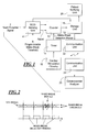
- FIG. 1 shows a schematic block diagram illustrating the heart stimulating device according to the present invention.
- FIG. 2 shows the present invention implemented on an ECG signal.
- FIG. 3 is a flow diagram illustrating the present invention.
- FIG. 1 shows a schematic block diagram illustrating the heart stimulating device according to the present invention.
- FIG. 1 shown an implantable heart stimulating device having an ECG sensing unit 4 adapted to receive heart potential signals 2 from sensing electrodes (not shown) arranged in connection with a patient's heart.
- the ECG sensing unit 4 includes amplifier means, filtering means and other signal processing means, which all are commonly used in implantable heart stimulating devices and therefore need not be further discussed herein.
- the ECG sensing unit 4 is provided with a programmable make-break threshold.
- the stimulating device further has a timer 14 adapted to generate a make-break detection period 12 , and a counter 10 .
- the counter 10 is adapted to count the number of times that the amplitude, preferably the absolute amplitude, of the heart potential signal exceeds the programmable make-break threshold during the make-break detection period. When the number of times is higher than a predetermined value, the counter 10 enables storage of the ECG obtained during the make-break detection period in an ECG storage unit 16 .
- the predetermined value is 3, 4 or 5, but any higher value may also
- the counter 10 and the timer 14 are preferably implemented in software.
- the make-break detection period is initiated when, and in parallel to, a refractory period, used in connection with normal heart stimulation procedures, is initiated by cardiac stimulating circuitry 18 .
- the make-break detection period may also be initiated by a premature ventricular contraction (PVC) or by another predefined intrinsic or stimulated heart event.
- PVC premature ventricular contraction
- the make-break detection period has a programmable length being a programmable percentage, between 20-100%, of the length of the escape interval used in connection with normal heart stimulation procedures by the cardiac stimulating circuitry 18 . If the detection period has a length of 100% of the escape interval the make-break signal detection is constantly activated, i.e. it enables detection of make-break signals during the entire heart cycle.
- the counter 10 is reset after each heart cycle by the ECG sensing unit 4 .
- the stored ECG may be analyzed, either by analysis circuitry or software (not shown) integrated in the medical device or in an external analyzer 20 in an external programming device , i.e., a “programmer”, in order to detect defects or damages of the electrode leads and/or electrode connections.
- a programmer through a communication session between a communication unit 22 in the implantable device and a communication unit 24 in the programmer, directly alerts the physician that a lead failure has been indicated.
- the implantable device may be provided with a patient notifying unit 26 adapted to notify the patient in case of detected anomalies.
- the notifying may be achieved by sound or by a generated vibration.
- FIG. 2 shows the present invention implemented based on an ECG signal.
- four heart cycles are shown by schematically illustrated QRS-complexes, either intrinsically initiated or stimulated by the heart stimulating device. In this case make-break detection periods are initiated when the QRS-complexes occur.
- make-break signals occur in the third heart cycle and in this specific example the absolute ECG signal exceed the make-break threshold at least nine times during the make-break detection period and if the predetermined value is e.g. four, the ECG signal during the third heart cycle will be stored.
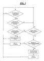
- FIG. 3 is a flow diagram schematically illustrating the present invention.
- the (absolute) ECG amplitude of the ECG-signal is compared to the programmable make-break threshold and if the amplitude is greater than the threshold it is determined, in the second box, whether the ECG-signal is measured within the make-break detection period. If within the period the count performed by the counter 10 is increased. If not within the detection period and the detection period has ended it is checked if the number of count is greater than a predetermined value. If it is not greater, the counter 10 is reset and the procedure returns to the first box for ECG amplitude measurement. If the number of counts during the detection period is greater than the predetermined value the ECG signal during the present heart cycle is stored in the storage unit 16 , for further analysis, and the counter 10 is reset.
- the physician has to decide if the electrode lead should be replaced or if any other procedures should be undertaken, e.g. reprogramming of the pacemaker.
- the present invention may naturally also be used to store ECG-signals having the erratic nature of a make-break signal, but not caused by e.g. an electrode damage, but instead caused by any heart event, e.g. R on T phenomenon or retrograde P-waves, for later analysis.
Abstract
Description
-
- The lead conductors make intermittent contact with each other due to an inner lead insulation defect/damage.
- The outer conductor makes intermittent contact with the pulse generator housing due to an outer insulation defect/damage (caused by the lead insulation being rubbed off against the pulse generator housing).
- The outer conductor makes intermittent contact with the outer conductor of another lead due to the fact that the leads have crossed each others in the pulse/ICD pocket and rubbed off each others insulations.
- The two ends of a broken lead conductor meet intermittently.
- A loose set screw.
- A lead connector pin not fully inserted into the pulse generator connector.
- The electrode(s) or outer insulation defects touches the electrodes of another lead inside the heart.
-
- Inhibition/triggering of pacemaker stimulation.
- Noise mode reversion with risk for T-wave stimulation.
- Triggering of inappropriate ICD therapy.
Claims (10)
Applications Claiming Priority (1)
| Application Number | Priority Date | Filing Date | Title |
|---|---|---|---|
| PCT/SE2006/000984 WO2008026969A1 (en) | 2006-08-28 | 2006-08-28 | Implantable heart stimulating device provided with means for obtaining an indication of a lead conductor fracture and a medical system comprising such a device |
Publications (2)
| Publication Number | Publication Date |
|---|---|
| US20100010558A1 US20100010558A1 (en) | 2010-01-14 |
| US8099166B2 true US8099166B2 (en) | 2012-01-17 |
Family
ID=39136159
Family Applications (1)
| Application Number | Title | Priority Date | Filing Date |
|---|---|---|---|
| US12/439,036 Expired - Fee Related US8099166B2 (en) | 2006-08-28 | 2006-08-28 | Implantable medical device with lead failure detection |
Country Status (3)
| Country | Link |
|---|---|
| US (1) | US8099166B2 (en) |
| EP (1) | EP2063957B1 (en) |
| WO (1) | WO2008026969A1 (en) |
Cited By (11)
| Publication number | Priority date | Publication date | Assignee | Title |
|---|---|---|---|---|
| US9199078B1 (en) | 2014-10-24 | 2015-12-01 | Medtronic, Inc. | Identifying lead problems using amplitudes of far-field cardiac events |
| US9302100B2 (en) | 2014-02-13 | 2016-04-05 | Medtronic, Inc. | Lead monitoring frequency based on lead and patient characteristics |
| US9399141B2 (en) | 2014-02-13 | 2016-07-26 | Medtronic, Inc. | Lead monitoring frequency based on lead and patient characteristics |
| US9409026B2 (en) | 2014-02-13 | 2016-08-09 | Medtronic, Inc. | Lead monitoring frequency based on lead and patient characteristics |
| US9440088B2 (en) | 2012-12-06 | 2016-09-13 | Cardiac Pacemakers, Inc. | Implanted lead analysis system and method |
| US9572990B2 (en) | 2012-07-11 | 2017-02-21 | Medtronic, Inc. | System and method for identifying lead dislodgement |
| US9764144B2 (en) | 2014-07-29 | 2017-09-19 | Cardiac Pacemakers, Inc. | Implanted lead analysis system and method |
| US9808170B2 (en) | 2013-03-15 | 2017-11-07 | Welch Allyn, Inc. | Electrode with charge-operated indicator |
| US9950155B2 (en) | 2013-03-15 | 2018-04-24 | Medtronic, Inc. | Identify insulation breach using electrograms |
| US10293155B2 (en) | 2013-03-15 | 2019-05-21 | Medtronic, Inc. | Identify insulation breach using electrograms |
| EP3542716A1 (en) | 2018-03-23 | 2019-09-25 | BIOTRONIK SE & Co. KG | Medical device and method for the evaluation of data regarding faults in an electrode lead |
Families Citing this family (3)
| Publication number | Priority date | Publication date | Assignee | Title |
|---|---|---|---|---|
| US8214054B2 (en) | 2009-04-07 | 2012-07-03 | Boston Scientific Neuromodulation Corporation | Systems and methods for coupling conductors to conductive contacts of electrical stimulation systems |
| JP6374708B2 (en) * | 2014-05-29 | 2018-08-15 | デクセリアルズ株式会社 | Ionic liquid, lubricant and magnetic recording medium |
| US20220370812A1 (en) * | 2020-01-05 | 2022-11-24 | Impulse Dynamics Nv | Lead condition testing in an implanted cardiac device |
Citations (6)
| Publication number | Priority date | Publication date | Assignee | Title |
|---|---|---|---|---|
| US5558098A (en) | 1995-11-02 | 1996-09-24 | Ventritex, Inc. | Method and apparatus for detecting lead sensing artifacts in cardiac electrograms |
| US5776168A (en) | 1996-04-03 | 1998-07-07 | Medtronic, Inc. | EGM recording system for implantable medical device |
| US5792205A (en) | 1996-10-21 | 1998-08-11 | Intermedics, Inc. | Cardiac pacemaker with bidirectional communication |
| US6236882B1 (en) | 1999-07-14 | 2001-05-22 | Medtronic, Inc. | Noise rejection for monitoring ECG's |
| US20030204215A1 (en) | 2002-04-29 | 2003-10-30 | Gunderson Bruce D. | Method and apparatus for identifying cardiac and non-cardiac oversensing using intracardiac electrograms |
| US20040162593A1 (en) | 2000-01-19 | 2004-08-19 | Medtronic, Inc. | Implantable lead functional status monitor and method |
-
2006
- 2006-08-28 EP EP06784118A patent/EP2063957B1/en not_active Not-in-force
- 2006-08-28 WO PCT/SE2006/000984 patent/WO2008026969A1/en active Application Filing
- 2006-08-28 US US12/439,036 patent/US8099166B2/en not_active Expired - Fee Related
Patent Citations (6)
| Publication number | Priority date | Publication date | Assignee | Title |
|---|---|---|---|---|
| US5558098A (en) | 1995-11-02 | 1996-09-24 | Ventritex, Inc. | Method and apparatus for detecting lead sensing artifacts in cardiac electrograms |
| US5776168A (en) | 1996-04-03 | 1998-07-07 | Medtronic, Inc. | EGM recording system for implantable medical device |
| US5792205A (en) | 1996-10-21 | 1998-08-11 | Intermedics, Inc. | Cardiac pacemaker with bidirectional communication |
| US6236882B1 (en) | 1999-07-14 | 2001-05-22 | Medtronic, Inc. | Noise rejection for monitoring ECG's |
| US20040162593A1 (en) | 2000-01-19 | 2004-08-19 | Medtronic, Inc. | Implantable lead functional status monitor and method |
| US20030204215A1 (en) | 2002-04-29 | 2003-10-30 | Gunderson Bruce D. | Method and apparatus for identifying cardiac and non-cardiac oversensing using intracardiac electrograms |
Non-Patent Citations (1)
| Title |
|---|
| Automatic Identification of Implantable Cardioverter-Defibrillator Lead Problems Using Intracardiac Electrograms, Gunderson et al., Computers in Cardiology, vol. 29 (2002) pp. 121-124. |
Cited By (13)
| Publication number | Priority date | Publication date | Assignee | Title |
|---|---|---|---|---|
| US9572990B2 (en) | 2012-07-11 | 2017-02-21 | Medtronic, Inc. | System and method for identifying lead dislodgement |
| US9440088B2 (en) | 2012-12-06 | 2016-09-13 | Cardiac Pacemakers, Inc. | Implanted lead analysis system and method |
| US9808170B2 (en) | 2013-03-15 | 2017-11-07 | Welch Allyn, Inc. | Electrode with charge-operated indicator |
| US11278728B2 (en) | 2013-03-15 | 2022-03-22 | Medtronic, Inc. | Identify insulation breach using electrograms |
| US10293155B2 (en) | 2013-03-15 | 2019-05-21 | Medtronic, Inc. | Identify insulation breach using electrograms |
| US9986930B2 (en) | 2013-03-15 | 2018-06-05 | Welch Allyn, Inc. | Electrode with charge-operated indicator |
| US9950155B2 (en) | 2013-03-15 | 2018-04-24 | Medtronic, Inc. | Identify insulation breach using electrograms |
| US9409026B2 (en) | 2014-02-13 | 2016-08-09 | Medtronic, Inc. | Lead monitoring frequency based on lead and patient characteristics |
| US9399141B2 (en) | 2014-02-13 | 2016-07-26 | Medtronic, Inc. | Lead monitoring frequency based on lead and patient characteristics |
| US9302100B2 (en) | 2014-02-13 | 2016-04-05 | Medtronic, Inc. | Lead monitoring frequency based on lead and patient characteristics |
| US9764144B2 (en) | 2014-07-29 | 2017-09-19 | Cardiac Pacemakers, Inc. | Implanted lead analysis system and method |
| US9199078B1 (en) | 2014-10-24 | 2015-12-01 | Medtronic, Inc. | Identifying lead problems using amplitudes of far-field cardiac events |
| EP3542716A1 (en) | 2018-03-23 | 2019-09-25 | BIOTRONIK SE & Co. KG | Medical device and method for the evaluation of data regarding faults in an electrode lead |
Also Published As
| Publication number | Publication date |
|---|---|
| EP2063957A1 (en) | 2009-06-03 |
| WO2008026969A1 (en) | 2008-03-06 |
| EP2063957B1 (en) | 2012-11-21 |
| EP2063957A4 (en) | 2010-06-16 |
| US20100010558A1 (en) | 2010-01-14 |
Similar Documents
| Publication | Publication Date | Title |
|---|---|---|
| US8099166B2 (en) | Implantable medical device with lead failure detection | |
| EP2125110B1 (en) | Gradually synchronized simultaneous atrial and ventricular pacing for cardiac rhythm discrimination | |
| US9675811B2 (en) | Display of temporally aligned heart information from separate implantable medical devices on an extracorporeal display | |
| US8626293B2 (en) | Method and system for identifying a potential lead failure in an implantable medical device | |
| US6937899B2 (en) | Ischemia detection | |
| EP1694407B1 (en) | Identifying lead-related conditions using impedance and oversensing criteria | |
| US7181268B2 (en) | Ischemia detection | |
| US7515961B2 (en) | Method and apparatus for dynamically monitoring, detecting and diagnosing lead conditions | |
| EP1423163B1 (en) | System for detecting myocardial ischemia | |
| US20150360041A1 (en) | Systems and methods for treating cardiac arrhythmias | |
| EP1590044B1 (en) | Automatic adjustment of capture test frequency | |
| US7966068B2 (en) | Detecting a lead fracture in an active implantable medical device for cardiac pacing resynchronization cardioversion and/or defibrillation | |
| US20220054835A1 (en) | Implantable system for stimulating a human or an animal heart | |
| EP2340083B1 (en) | Selective heart pacing | |
| US20050004607A1 (en) | Cardiac stimulating and detecting device, system and method for identifying far field signals |
Legal Events
| Date | Code | Title | Description |
|---|---|---|---|
| AS | Assignment |
Owner name: ST. JUDE MEDICAL AB, SWEDEN Free format text: ASSIGNMENT OF ASSIGNORS INTEREST;ASSIGNORS:SCHULLER, HANS;LINDGREN, ANDERS;REEL/FRAME:022316/0473;SIGNING DATES FROM 20090220 TO 20090223 Owner name: ST. JUDE MEDICAL AB, SWEDEN Free format text: ASSIGNMENT OF ASSIGNORS INTEREST;ASSIGNORS:SCHULLER, HANS;LINDGREN, ANDERS;SIGNING DATES FROM 20090220 TO 20090223;REEL/FRAME:022316/0473 |
|
| ZAAA | Notice of allowance and fees due |
Free format text: ORIGINAL CODE: NOA |
|
| ZAAB | Notice of allowance mailed |
Free format text: ORIGINAL CODE: MN/=. |
|
| STCF | Information on status: patent grant |
Free format text: PATENTED CASE |
|
| FPAY | Fee payment |
Year of fee payment: 4 |
|
| MAFP | Maintenance fee payment |
Free format text: PAYMENT OF MAINTENANCE FEE, 8TH YEAR, LARGE ENTITY (ORIGINAL EVENT CODE: M1552); ENTITY STATUS OF PATENT OWNER: LARGE ENTITY Year of fee payment: 8 |
|
| FEPP | Fee payment procedure |
Free format text: MAINTENANCE FEE REMINDER MAILED (ORIGINAL EVENT CODE: REM.); ENTITY STATUS OF PATENT OWNER: LARGE ENTITY |
|
| LAPS | Lapse for failure to pay maintenance fees |
Free format text: PATENT EXPIRED FOR FAILURE TO PAY MAINTENANCE FEES (ORIGINAL EVENT CODE: EXP.); ENTITY STATUS OF PATENT OWNER: LARGE ENTITY |
|
| STCH | Information on status: patent discontinuation |
Free format text: PATENT EXPIRED DUE TO NONPAYMENT OF MAINTENANCE FEES UNDER 37 CFR 1.362 |
|
| FP | Lapsed due to failure to pay maintenance fee |
Effective date: 20240117 |