US8093038B2 - Apparatus and method for encapsulating pancreatic cells - Google Patents
Apparatus and method for encapsulating pancreatic cells Download PDFInfo
- Publication number
- US8093038B2 US8093038B2 US11/901,448 US90144807A US8093038B2 US 8093038 B2 US8093038 B2 US 8093038B2 US 90144807 A US90144807 A US 90144807A US 8093038 B2 US8093038 B2 US 8093038B2
- Authority
- US
- United States
- Prior art keywords
- particle
- particles
- tube
- fluid layer
- withdrawal tube
- Prior art date
- Legal status (The legal status is an assumption and is not a legal conclusion. Google has not performed a legal analysis and makes no representation as to the accuracy of the status listed.)
- Expired - Fee Related, expires
Links
Images


Classifications
-
- C—CHEMISTRY; METALLURGY
- C12—BIOCHEMISTRY; BEER; SPIRITS; WINE; VINEGAR; MICROBIOLOGY; ENZYMOLOGY; MUTATION OR GENETIC ENGINEERING
- C12N—MICROORGANISMS OR ENZYMES; COMPOSITIONS THEREOF; PROPAGATING, PRESERVING, OR MAINTAINING MICROORGANISMS; MUTATION OR GENETIC ENGINEERING; CULTURE MEDIA
- C12N11/00—Carrier-bound or immobilised enzymes; Carrier-bound or immobilised microbial cells; Preparation thereof
- C12N11/02—Enzymes or microbial cells immobilised on or in an organic carrier
- C12N11/04—Enzymes or microbial cells immobilised on or in an organic carrier entrapped within the carrier, e.g. gel or hollow fibres
Definitions
- This invention relates generally to an apparatus and method for coating or encapsulating small particles, namely micro-sized particles and sub-micron particles, and, more particularly, to a device for encapsulation of living cells, e.g., pancreatic islet cells, intended for implantation into patients.
- pancreatic islets More than one million people in the U.S. suffer from Type I diabetes, a disease in which pancreatic islets are no longer able to control glucose levels in the blood. The expectancy and quality of life of these patients is greatly compromised by diabetic complications that include retinopathies, renal failure, and vascular disease.
- An alternate therapeutic modality to regular insulin injections is transplantation of pancreatic islets from transgenic (allotransplantation) or nontransgenic (xenotransplantation) organisms.
- transplanted islets are immunoisolated by enclosing them individually into microcapsules comprised of structurally stable, semipermeable membranes. The structural stability and selective permeability of the membrane ensures long-term viability and functionality of the islets.
- Encapsulation methods generally include droplet generation, emulsion formation, polyelectrolyte multilayering, and direct polymerization from a surface-adsorbed initiator. Encapsulation methods are often restricted in terms of chemical composition, uniformity and thickness of the membrane, polymerization schemes, and applied stress to pancreatic islets. There is a need for an improved method for encapsulating islet cells.
- a general object of the invention is to provide a cell encapsulation device with high yields of encapsulated pancreatic islets with long-term viability and functionality.
- the general object of the invention can be attained, at least in part, through an apparatus for coating micron-sized or sub-micron-sized particles.
- the coating apparatus includes an encapsulation chamber including therein a first fluid layer of water or an aqueous solution disposed on a second fluid layer of a fluid incompatible with the first layer.
- the coating apparatus includes a particle feed tube with a particle passage in combination with a feed tube opening at a discharge end of the feed tube. The feed tube opening is disposed in the first fluid layer.
- a particle withdrawal tube includes a first end in combination with the encapsulation chamber and is connected at a second end to a filtration device.
- the invention further comprehends an apparatus for coating micron-sized or sub-micron-sized particles.
- the coating apparatus includes an encapsulation chamber enclosing an aqueous fluid layer disposed on an oil fluid layer, and a particle feed device in combination with the encapsulation chamber by a particle feed tube.
- the particle feed tube includes a particle passage and a feed tube opening disposed in the aqueous fluid layer.
- the particle feed device includes a particle discharge channel having a particle discharge channel opening in combination with a first end of the particle passage.
- the particle feed device further includes a polymer solution injection channel adjacent the particle discharge channel and having an injection channel opening in combination with the first end of the particle passage.
- a particle withdrawal tube is connected at a first end to the encapsulation chamber and connected at a second end to a filtration device.
- a pump is in combination with the particle withdrawal tube.
- the invention still further comprehends a method of coating micron-sized or sub-micron-sized particles.
- the method includes: mixing the particles with a polymer precursor solution in a particle feed tube; discharging the particles and the polymer precursor solution from the particle feed tube into an aqueous first fluid layer in an encapsulation chamber, the aqueous first fluid layer disposed on a second fluid layer formed of a fluid incompatible with the aqueous first fluid layer; removing the particles and at least a portion of the polymer precursor solution from the encapsulation chamber through a particle withdrawal tube; and polymerizing a polymer precursor of the polymer precursor solution within the particle withdrawal tube to coat the particles with a polymer material.
- the mixing of the particles with a polymer precursor solution in the particle passage comprises hydrodynamically aligning the particles into a particle stream within the particle passage with at least one stream of the polymer precursor solution.
- removing the particles and at least a portion of the polymer precursor solution from the encapsulation chamber through a particle withdrawal tube comprises: placing an opening at an end of the particle withdrawal tube at a predetermined distance from an interface between the first fluid layer and the second fluid layer; drawing a stream of both the first fluid layer and the second fluid layer through the opening and into the particle withdrawal tube; and drawing the particles and the at least a portion of the polymer precursor solution through the opening and into the particle withdrawal tube.
- the polymerization of the polymer precursor of the polymer precursor solution within the particle withdrawal tube to coat the particles with the polymer material includes applying light from a laser to the particles and the at least a portion of the polymer precursor solution within the particle withdrawal tube.
- the device and method of this invention are particularly useful for encapsulation of pancreatic islet cells within a polymer film for implantation into patients suffering from Type I diabetes.
- the invention utilizes the method of selective withdrawal from a two-layer water-oil system for coating each islet with an aqueous polymeric coat. Islets together with an aqueous polymer solution are fed by the feed device that utilizes the principle of hydrodynamic focusing in order to ensure encapsulation of individual islets.
- the polymer in the aqueous coat is subsequently crosslinked by being exposed to laser light to produce structurally stable microcapsules of controllable thickness of the order of tens of microns.
- Encapsulated islets are removed from the encapsulation chamber by a valveless pump and recovered by filtration or centrifugation.
- the method and device of this invention ensure timely encapsulation of a number of islets, adequate for clinical trials, in microcapsules enclosed by semipermeable, hydrogel membranes of uniform thickness, that ensure long-term viability and functionality of the islets.
- FIG. 1 illustrates a coating apparatus according to one embodiment of this invention.
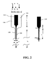
- FIG. 2 is a schematic of a feed device for use in the coating apparatus on FIG. 1 , according to one embodiment of this invention.
- FIGS. 3A-D illustrate features and operation of the pump for use in the coating apparatus on FIG. 1 , according to one embodiment of this invention.
- FIG. 4 illustrates the equilibrium position of the incompatible fluid interface, according to one embodiment of this invention.
- FIG. 5 illustrates the operation of a disk centrifuge for use in the coating apparatus on FIG. 1 , according to one embodiment of this invention.
- FIG. 6 illustrates a model of roll coating for determining a thickness of a encapsulating shell, according to one embodiment of this invention.
- FIG. 1 generally illustrates a coating apparatus 100 (not to scale) according to one embodiment of this invention for coating micron-sized or sub-micron-sized particles.
- the apparatus 100 includes an encapsulation chamber 102 with a first fluid layer 104 disposed on a second fluid layer 106 .
- the second fluid layer 106 includes a liquid that is incompatible with the first fluid layer 104 , thereby allowing the first fluid layer 104 to sit atop of the second fluid layer 106 .
- the first fluid layer 104 includes water or an aqueous solution.
- the second fluid layer 106 can include any liquid that in incompatible with, and thus separates from, water, such as an oil.
- the second fluid layer 106 includes a chlorinated hydrocarbon oil such as sold under the name PAROIL, available from Dover Chemical Corporation, Dover, Ohio.
- a particle feed device 110 is in combination with the encapsulation chamber 102 so as to introduce thereto the particles 112 to be coated.
- the particles 112 can be any particles, but the apparatus of this invention is particularly suited for coating micron-sized particles and smaller.
- the particles 112 are living cells or cell aggregates, and the invention will be described below with reference to pancreatic islet cells as the particles 112 .
- the particle feed device 110 shown in FIG. 1 includes a particle discharge channel 114 adjacent and between a first polymer solution injection channel 116 and a second polymer solution injection channel 118 .
- the particle discharge channel includes a particle discharge channel opening 120 through which the islet cells 112 enter a particle passage 134 of a particle feed tube 130 at a feed tube first end 132 .
- Each of the polymer solution injection channels 116 and 118 includes an injection channel opening 122 and 124 (respectively) in combination with the first end 132 and through which a polymer solution enters the particle passage 134 of the particle feed tube 130 .
- FIG. 2 is a schematic of the feed device 110 , which is desirably constructed of a plastic such as poly(methyl methacrylate) (PMMA) material.
- the islets 112 are injected from the central particle discharge channel 114 and focused hydrodynamically into an aligned single-islet-file stream through the particle passage 134 , constrained by polymer precursor solution flows from the two lateral injection channels 116 and 118 .
- the feed device of FIG. 2 follows principles discussed in Lee et al., “Hydrodynamic Focusing for a Micromachined Flow Cytometer,” Trans. ASME 123, 672 (2001), which are hereby incorporated by reference.
- the polymer solution used in the particle coating apparatus of this invention can be any suitable polymeric solution for coating the cells 112 .
- the polymeric solution includes a precursor of the polymer intended to coat the islet cells 112 .
- the aqueous polymeric solution for the coating material is contained in both the polymer solution injected through the injection channels 116 and 118 and in the aqueous first fluid layer 104 .
- suitable polymers or polymer precursors include PEG-based polymers, such as PEG-diacrylate.
- the particle feed tube 130 includes a feed tube opening 136 at a feed tube second end 138 that is opposite the first end 132 .
- the feed tube opening 136 is disposed in the aqueous first fluid layer 104 at a predetermined distance above a fluid interface 140 (e.g., a water-oil interface).
- a particle withdrawal tube 142 is in combination with the encapsulation chamber 102 and has a first end 144 disposed at a predetermined distance below the fluid interface 140 .
- An opposing second end 146 of the particle withdrawal tube 142 is connected to a filtration device 150 .
- a pump 152 is in combination with the particle withdrawal tube 142 upstream of the filtration device 150 .
- the first end 144 includes a withdrawal tube opening 148 disposed within the second fluid layer 106 .
- the pump 152 withdraws oil through the particle withdrawal tube 142 at a rate that defines the flow as laminar.
- the flow rate is controlled to secure hydrodynamic stresses levels much below the critical stress that proves to be damaging to the living cells of the islets 112 . If the withdrawal tube 142 is placed below the fluid interface 140 at a distance less than a critical distance, a thin spout 154 of the first fluid layer 104 is entrained with the oil. Islets 112 arriving at the fluid interface 140 , by design, exactly above the opening 148 of the withdrawal tube 142 , are drawn in the spout 154 and enter the withdrawal tube 142 .
- the islet 112 diameter is greater than a diameter of the spout 154 at the opening 148 , so that the balance of interfacial and viscous forces causes the spout 154 to break both above and below the entrained islet 112 .
- a thin layer of the aqueous polymeric solution surrounds the entrained islet 112 within the withdrawal tube 142 .
- the polymeric solution with the islets 112 flows as a string of circular cross section, along the axis of the withdrawal tube 142 , while the oil flows in the annulus between the tube wall and the lateral surface of the string.
- the islets 112 After the islets 112 have been entrained into the withdrawal tube 142 and coated with the polymer solution, the islets 112 are exposed to light from a light source 160 , such as, for example, 514 nm light of an argon-ion laser, that is in light discharge alignment with a portion of the withdrawal tube 142 .
- the light source 160 is used to polymerize the polymer precursor within the polymer solution to coat the islets 112 .
- the cell culture medium of islets 112 injected through particle discharge channel 114 and/or the polymer solution through injection channel 116 and/or 118 includes eosin-Y as a photoinitiator, 1-vinyl-2-pyrrolidinone as an accelerator and triethanolamine as a coinititiator for polymerization.
- the light excites eosin-Y and initiates free-radical polymerization to produce, for example, a poly(ethylene glycol) (PEG) hydrogel from a PEG-diacrylate precursor.
- PEG poly(ethylene glycol)
- the withdrawal tube 142 includes a coiled portion 156 which is used to provide sufficient time within the light beam for polymer crosslinking and hydrogel formation.
- the frictional pressure drop associated with the flow in the coiled part of the withdrawal tube is a function of the Dean number, which is nothing but the Reynolds number multiplied by the ratio of the tube-to-coil-curvature radii.
- the thickness of the resulting microcapsule shell enclosing an individual islet is controllable to within tens of a micron.
- the coating apparatus 100 of FIG. 1 also includes an oil reservoir 160 connected to the encapsulation chamber 102 by a pump 162 .
- a level sensor 164 measures the level of the second fluid layer 106 and the layer 106 is adjusted according to need to maintain the desired distance between the fluid interface 140 and the withdrawal tube 142 .
- FIGS. 3A-D illustrate features and operation of the pump 152 .
- the pump 152 is a valveless diffuser-nozzle pump that has no interior mechanical parts for transporting mammalian cells with minimal and preferably no damage.
- the pump 152 is used to generate a selective withdrawal flow and remove the encapsulated islets 112 from the encapsulation chamber 102 .
- the pump 152 is a diaphragm pump that uses two diffusers 170 and 172 as flow directing elements.
- the pump 152 is desirably made of a glassy plastic material (e.g., PMMA) with a flexible top portion 174 (e.g., poly(dimethyl acrylate) (PDMA)) over an internal fluid cavity.
- PMMA glassy plastic material
- PDMA poly(dimethyl acrylate)
- a piezoelectric (PZT) patch is bonded to the flexible top 174 of the pumping chamber, e.g., with epoxy resin, and is used in connection with applied AC voltage to set the three-layer (PZT-epoxy-PDMA) plate into vibration at a frequency, below the frequency of the natural frequency of the PDMA plate.
- the vibrating plate drives fluid flow, and at the same time, the fluid increases the resistance to the vibration (fluid flow and plate vibration are coupled). If the action of the fluid is negligible, the plate will vibrate at the same frequency as the piezoelectric (excitation) force for small amplitude vibrations.
- the pump cycle can be divided into a supply and a pump mode.
- the fluid cavity volume increases and a larger amount of the fluid flows into the cavity through the input element, i.e., diffuser 170 , than through the output element, i.e., diffuser 172 , which acts as a nozzle.
- the pump mode when the fluid cavity volume decreases, a larger amount of fluid flows out of the cavity through the output element 172 , which acts as a diffuser, than the input element 170 , which acts as a nozzle.
- the result for the complete pump cycle is that the net volume is transported from the input to the output side of the pump.
- valveless pump 152 The ability of the valveless pump 152 to direct the flow in a preferential direction is measured by the rectification efficiency
- rectification efficiency is, in turn, related to the efficiency of the nozzle-diffuser element, ⁇ , which is defined as the ratio of the total pressure loss coefficient in the nozzle direction to that for the flow in the diffusion direction,
- K n , t K d , t ( K n , en + K n ) ⁇ ( A a 2 / A b 2 ) + K n , ex K d , en + K d + K d , ex ⁇ ( A a 2 / A b 2 ) , where the subscripts “t”, “en”, “ex” refer to total, entrance and exit, respectively, and K d and K n are the frictional loss coefficients in the “body” of the diffuser and nozzle, respectively.
- the average flow rate through the pump 152 is given by
- the encapsulated islets 112 are recovered in filtration device 150 shown in FIG. 1 , for example, by mechanical filtration or centrifugation.
- High-retention filtration devices e.g., spin-filters, can be utilized.
- Centrifugation can also be utilized, especially if it is desirable to recover the encapsulated islets 112 in a cell culture medium for the survival of islet cells.
- a buffer (aqueous) medium is desirably fed to the centrifuge simultaneously with the encapsulated-islets-containing oil, such as into a disk centrifuge 200 shown in FIG. 5 .
- the feed solution F which includes the oil, water and islets, is introduced into the disk centrifuge 200 .
- the heavy phase H (oil) and light phase L (water) separate within the centrifuge and are pumped out, as indicated by the respective arrows.
- the encapsulated islets are then recovered in the cell culture medium, which comprises the light phase.
- a coating apparatus was constructed according to the following. All the parts of the coating apparatus, except for the top plate of the pumping chamber in the valveless pump, were made out of poly(methyl methacrylate) PMMA. The top plate of the pumping chamber was made out of poly(dimethyl acrylate).
- the particle feeding device for introducing, under hydrodynamic focusing, islets and precursor polymer solution was as shown in FIG. 2 , with design parameters given in Table 1.
- the encapsulation chamber had a square cross section with 12.5 cm sides, and contained two fluid layers. Each layer had a height of 24 cm, on top of each other.
- the upper layer was an aqueous solution containing the polymeric precursor.
- the lower layer was PAROIL-152 (density of 1.26 g/cm 3 ), from Dover Chemical Corporation.
- the feed tube of the particle feed device entered the aqueous layer and the feed tube opening was located at a distance of 7 mm above the water-oil interface.
- the islets having an average diameter of about 150 ⁇ m, were fed at the rate of one islet per second and reached a terminal velocity of about 700 ⁇ m/s at about 0.03 ⁇ m below the feed tube opening.
- the opening of the lower part of the feed tube acted as a flow source.
- an inlet opening of the withdrawal tube having a diameter of 7.9 mm, acted as a flow sink of strength imposed by the valveless pump.
- the flow problem becomes selective withdrawal from a viscous two-layer system, with fluids of different viscosity in each layer, a source in the top layer and a sink of equal strength in the bottom layer and at equal distance on each side from the fluid-fluid interface.
- Q c the dimensionless sink strength
- buoyancy and surface tension act as counteracting effects to the strain of the sink.
- a source is present in the upper layer, then the strain due to the source would be in such a direction as to augment the effects of the restoring forces (buoyancy and surface tension) and to stabilize the interfacial position.
- selective withdrawal occurs through a sink in the bottom layer, while a source in the upper layer feeds islets in a solution of polymer precursor.
- a fluid drop of radius a in extensional flow of strain E will deform if 4 ⁇ Ea/ ⁇ >0.65.
- the tip of the interfacial peak is expected to behave in a manner analogous to the fluid drop.
- the equivalent criterion for instability is 2Qa/[ ⁇ (1 ⁇ f(0)) 3 ]>0.65, where a scales with the radius of the tip.
- the same quantity determined by numerical solution is slightly different from the estimate of the asymptotic solution, the difference being entirely due to the O(Q 2 ) term.
- the upper-to-lower-fluid flux ratio, ⁇ is estimated to be equal to 0.46, which for the withdrawal rate of 0.3 cm 3 /s, results in average withdrawal velocities for the aqueous polymeric solution and the oil of 0.28 cm/s and 0.61 cm/s, respectively.
- the withdrawal tube began as a straight vertical tube and included a coiled tube of length 190 cm, helix diameter 2.5 cm, and coil pitch of 2.4 cm.
- the pressure drop in the coiled part of the withdrawal tube which is a function of the Dean number (i.e., Reynolds number multiplied by the square root of the ratio of the tube radius to the radius of curvature of the coil), was estimated to be 1.62 psi.
- a withdrawal rate of 0.3 cm 3 /s was imposed on the system by a valveless diffuser/nozzle pump.
- nozzle-diffuser elements of the pump electrical-mechanical coupling coefficient, d 31 , layer thickness, h, Young modulus, E, Poisson ratio, v, are given below, where subscripts p, b and pzt refer to PDMS, bonding material, and PZT layer, respectively.
- the nozzle-diffuser pump elements characteristics are given in Table 3.
- the volumetric amplitude, V o can be determined from the solution to the biharmonic equation for the deflection of the membrane.
- the deflection of the membrane is a function of the excitation (piezoelectric) force or the potential of the electric field applied.
- the desired flow rate of 0.3 cm 3 /s for this example was achieved with an AC electric field of potential 10V and a frequency of 90 Hz.
- N 1 ⁇ ⁇ ⁇ ⁇ U ⁇ ( H o R ) 1 / 2 , where ⁇ is the surface tension, ⁇ the viscosity of the fluid, U the average velocity of the fluid with regard to the roll (in this case particle), H o the minimum distance of the roll from the center of mass of fluid and R the radius of the roll (again, in this case particle).
- H o 551 ⁇ m
- N 1 1994
- the thickness of the coat of the pancreatic islets, of diameter 150 ⁇ m is estimated to be 42 ⁇ m.
- the invention provides a device and method for encapsulating particles, such as pancreatic islet cells for implants in patients with diabetes I.
- This device can be also used for coating other micron-size particles with a stable, crosslinked-polymer film of uniform and controllable thickness.
- it is particularly suitable for encapsulating living cells or cell aggregates, on an individual basis, i.e., one cell or one aggregate of cells per capsule.
- the obtained capsule shell is a stable, selectively permeable crosslinked-polymer membrane.
- selectively permeable crosslinked-polymer membrane means that there is a cut-off size for species diffusing through the membrane, which correlates with the crosslinking density.
- the capsule shell thus produced provides immunoprotection to the living cells, when implanted, and ensures passage of cell nutrients and cell products, e.g., insulin and waste, to and from the interior of the capsule, respectively.
Abstract
An apparatus and method for coating micron-sized or sub-micron-sized particles such as living cells. The coating apparatus includes an encapsulation chamber enclosing a two-layer water-oil system for coating each islet cell with an aqueous polymeric coat. Islets together with an aqueous polymer solution are fed by a feed device that utilizes the principle of hydrodynamic focusing in order to ensure encapsulation of individual islets. The polymer in the aqueous coat is subsequently crosslinked by being exposed to laser light to produce structurally stable microcapsules of controllable thickness of the order of tens of microns. Encapsulated islets are removed from the encapsulation chamber by a valveless pump and recovered by filtration or centrifugation.
Description
This invention relates generally to an apparatus and method for coating or encapsulating small particles, namely micro-sized particles and sub-micron particles, and, more particularly, to a device for encapsulation of living cells, e.g., pancreatic islet cells, intended for implantation into patients.
More than one million people in the U.S. suffer from Type I diabetes, a disease in which pancreatic islets are no longer able to control glucose levels in the blood. The expectancy and quality of life of these patients is greatly compromised by diabetic complications that include retinopathies, renal failure, and vascular disease. An alternate therapeutic modality to regular insulin injections is transplantation of pancreatic islets from transgenic (allotransplantation) or nontransgenic (xenotransplantation) organisms. To suppress rejection by the recipient's immune system, transplanted islets are immunoisolated by enclosing them individually into microcapsules comprised of structurally stable, semipermeable membranes. The structural stability and selective permeability of the membrane ensures long-term viability and functionality of the islets.
Current methods for encapsulation generally include droplet generation, emulsion formation, polyelectrolyte multilayering, and direct polymerization from a surface-adsorbed initiator. Encapsulation methods are often restricted in terms of chemical composition, uniformity and thickness of the membrane, polymerization schemes, and applied stress to pancreatic islets. There is a need for an improved method for encapsulating islet cells.
A general object of the invention is to provide a cell encapsulation device with high yields of encapsulated pancreatic islets with long-term viability and functionality.
The general object of the invention can be attained, at least in part, through an apparatus for coating micron-sized or sub-micron-sized particles. The coating apparatus includes an encapsulation chamber including therein a first fluid layer of water or an aqueous solution disposed on a second fluid layer of a fluid incompatible with the first layer. The coating apparatus includes a particle feed tube with a particle passage in combination with a feed tube opening at a discharge end of the feed tube. The feed tube opening is disposed in the first fluid layer. A particle withdrawal tube includes a first end in combination with the encapsulation chamber and is connected at a second end to a filtration device.
The invention further comprehends an apparatus for coating micron-sized or sub-micron-sized particles. The coating apparatus includes an encapsulation chamber enclosing an aqueous fluid layer disposed on an oil fluid layer, and a particle feed device in combination with the encapsulation chamber by a particle feed tube. The particle feed tube includes a particle passage and a feed tube opening disposed in the aqueous fluid layer. The particle feed device includes a particle discharge channel having a particle discharge channel opening in combination with a first end of the particle passage. The particle feed device further includes a polymer solution injection channel adjacent the particle discharge channel and having an injection channel opening in combination with the first end of the particle passage. A particle withdrawal tube is connected at a first end to the encapsulation chamber and connected at a second end to a filtration device. A pump is in combination with the particle withdrawal tube.
The invention still further comprehends a method of coating micron-sized or sub-micron-sized particles. The method includes: mixing the particles with a polymer precursor solution in a particle feed tube; discharging the particles and the polymer precursor solution from the particle feed tube into an aqueous first fluid layer in an encapsulation chamber, the aqueous first fluid layer disposed on a second fluid layer formed of a fluid incompatible with the aqueous first fluid layer; removing the particles and at least a portion of the polymer precursor solution from the encapsulation chamber through a particle withdrawal tube; and polymerizing a polymer precursor of the polymer precursor solution within the particle withdrawal tube to coat the particles with a polymer material. Desirably, the mixing of the particles with a polymer precursor solution in the particle passage comprises hydrodynamically aligning the particles into a particle stream within the particle passage with at least one stream of the polymer precursor solution.
In one embodiment, removing the particles and at least a portion of the polymer precursor solution from the encapsulation chamber through a particle withdrawal tube comprises: placing an opening at an end of the particle withdrawal tube at a predetermined distance from an interface between the first fluid layer and the second fluid layer; drawing a stream of both the first fluid layer and the second fluid layer through the opening and into the particle withdrawal tube; and drawing the particles and the at least a portion of the polymer precursor solution through the opening and into the particle withdrawal tube.
The polymerization of the polymer precursor of the polymer precursor solution within the particle withdrawal tube to coat the particles with the polymer material includes applying light from a laser to the particles and the at least a portion of the polymer precursor solution within the particle withdrawal tube.
The device and method of this invention are particularly useful for encapsulation of pancreatic islet cells within a polymer film for implantation into patients suffering from Type I diabetes. The invention utilizes the method of selective withdrawal from a two-layer water-oil system for coating each islet with an aqueous polymeric coat. Islets together with an aqueous polymer solution are fed by the feed device that utilizes the principle of hydrodynamic focusing in order to ensure encapsulation of individual islets. The polymer in the aqueous coat is subsequently crosslinked by being exposed to laser light to produce structurally stable microcapsules of controllable thickness of the order of tens of microns. Encapsulated islets are removed from the encapsulation chamber by a valveless pump and recovered by filtration or centrifugation. The method and device of this invention ensure timely encapsulation of a number of islets, adequate for clinical trials, in microcapsules enclosed by semipermeable, hydrogel membranes of uniform thickness, that ensure long-term viability and functionality of the islets.
Other objects and advantages will be apparent to those skilled in the art from the following detailed description taken in conjunction with the appended claims and drawings.
A particle feed device 110 is in combination with the encapsulation chamber 102 so as to introduce thereto the particles 112 to be coated. The particles 112 can be any particles, but the apparatus of this invention is particularly suited for coating micron-sized particles and smaller. In one embodiment of this invention, the particles 112 are living cells or cell aggregates, and the invention will be described below with reference to pancreatic islet cells as the particles 112.
The particle feed device 110 shown in FIG. 1 includes a particle discharge channel 114 adjacent and between a first polymer solution injection channel 116 and a second polymer solution injection channel 118. The particle discharge channel includes a particle discharge channel opening 120 through which the islet cells 112 enter a particle passage 134 of a particle feed tube 130 at a feed tube first end 132. Each of the polymer solution injection channels 116 and 118 includes an injection channel opening 122 and 124 (respectively) in combination with the first end 132 and through which a polymer solution enters the particle passage 134 of the particle feed tube 130.
The polymer solution used in the particle coating apparatus of this invention can be any suitable polymeric solution for coating the cells 112. Desirably, the polymeric solution includes a precursor of the polymer intended to coat the islet cells 112. In one embodiment of this invention the aqueous polymeric solution for the coating material is contained in both the polymer solution injected through the injection channels 116 and 118 and in the aqueous first fluid layer 104. Examples of suitable polymers or polymer precursors include PEG-based polymers, such as PEG-diacrylate.
Referring again to FIG. 1 , the particle feed tube 130 includes a feed tube opening 136 at a feed tube second end 138 that is opposite the first end 132. The feed tube opening 136 is disposed in the aqueous first fluid layer 104 at a predetermined distance above a fluid interface 140 (e.g., a water-oil interface).
A particle withdrawal tube 142 is in combination with the encapsulation chamber 102 and has a first end 144 disposed at a predetermined distance below the fluid interface 140. An opposing second end 146 of the particle withdrawal tube 142 is connected to a filtration device 150. A pump 152 is in combination with the particle withdrawal tube 142 upstream of the filtration device 150. The first end 144 includes a withdrawal tube opening 148 disposed within the second fluid layer 106.
The pump 152 withdraws oil through the particle withdrawal tube 142 at a rate that defines the flow as laminar. The flow rate is controlled to secure hydrodynamic stresses levels much below the critical stress that proves to be damaging to the living cells of the islets 112. If the withdrawal tube 142 is placed below the fluid interface 140 at a distance less than a critical distance, a thin spout 154 of the first fluid layer 104 is entrained with the oil. Islets 112 arriving at the fluid interface 140, by design, exactly above the opening 148 of the withdrawal tube 142, are drawn in the spout 154 and enter the withdrawal tube 142. Desirably, the islet 112 diameter is greater than a diameter of the spout 154 at the opening 148, so that the balance of interfacial and viscous forces causes the spout 154 to break both above and below the entrained islet 112. At this point, a thin layer of the aqueous polymeric solution surrounds the entrained islet 112 within the withdrawal tube 142. The polymeric solution with the islets 112 flows as a string of circular cross section, along the axis of the withdrawal tube 142, while the oil flows in the annulus between the tube wall and the lateral surface of the string.
After the islets 112 have been entrained into the withdrawal tube 142 and coated with the polymer solution, the islets 112 are exposed to light from a light source 160, such as, for example, 514 nm light of an argon-ion laser, that is in light discharge alignment with a portion of the withdrawal tube 142. The light source 160 is used to polymerize the polymer precursor within the polymer solution to coat the islets 112. In one embodiment of this invention the cell culture medium of islets 112 injected through particle discharge channel 114 and/or the polymer solution through injection channel 116 and/or 118 includes eosin-Y as a photoinitiator, 1-vinyl-2-pyrrolidinone as an accelerator and triethanolamine as a coinititiator for polymerization. The light excites eosin-Y and initiates free-radical polymerization to produce, for example, a poly(ethylene glycol) (PEG) hydrogel from a PEG-diacrylate precursor.
As shown in FIG. 1 , the withdrawal tube 142 includes a coiled portion 156 which is used to provide sufficient time within the light beam for polymer crosslinking and hydrogel formation. As will be appreciated, the frictional pressure drop associated with the flow in the coiled part of the withdrawal tube is a function of the Dean number, which is nothing but the Reynolds number multiplied by the ratio of the tube-to-coil-curvature radii. Using the apparatus of this invention, the thickness of the resulting microcapsule shell enclosing an individual islet is controllable to within tens of a micron.
The coating apparatus 100 of FIG. 1 also includes an oil reservoir 160 connected to the encapsulation chamber 102 by a pump 162. A level sensor 164 measures the level of the second fluid layer 106 and the layer 106 is adjusted according to need to maintain the desired distance between the fluid interface 140 and the withdrawal tube 142.
As shown in FIGS. 3C and 3D , the pump cycle can be divided into a supply and a pump mode. In the supply mode, the fluid cavity volume increases and a larger amount of the fluid flows into the cavity through the input element, i.e., diffuser 170, than through the output element, i.e., diffuser 172, which acts as a nozzle. In the pump mode, when the fluid cavity volume decreases, a larger amount of fluid flows out of the cavity through the output element 172, which acts as a diffuser, than the input element 170, which acts as a nozzle. The result for the complete pump cycle is that the net volume is transported from the input to the output side of the pump.
The ability of the valveless pump 152 to direct the flow in a preferential direction is measured by the rectification efficiency,
where the subscripts “+” and “−” refer to flow in the forward and backward directions. The rectification efficiency is, in turn, related to the efficiency of the nozzle-diffuser element, η, which is defined as the ratio of the total pressure loss coefficient in the nozzle direction to that for the flow in the diffusion direction,
where the subscripts “t”, “en”, “ex” refer to total, entrance and exit, respectively, and Kd and Kn are the frictional loss coefficients in the “body” of the diffuser and nozzle, respectively.
The average flow rate through the pump 152 is given by
where ω is the angular frequency of the applied electric field and Vo is volumetric amplitude of the three-layer membrane.
The encapsulated islets 112 are recovered in filtration device 150 shown in FIG. 1 , for example, by mechanical filtration or centrifugation. High-retention filtration devices, e.g., spin-filters, can be utilized. Centrifugation can also be utilized, especially if it is desirable to recover the encapsulated islets 112 in a cell culture medium for the survival of islet cells. In this case, a buffer (aqueous) medium is desirably fed to the centrifuge simultaneously with the encapsulated-islets-containing oil, such as into a disk centrifuge 200 shown in FIG. 5 . In FIG. 5 , the feed solution F, which includes the oil, water and islets, is introduced into the disk centrifuge 200. The heavy phase H (oil) and light phase L (water) separate within the centrifuge and are pumped out, as indicated by the respective arrows. The encapsulated islets are then recovered in the cell culture medium, which comprises the light phase.
The present invention is described in further detail in connection with the following example which illustrates or simulates various aspects involved in the practice of the invention. It is to be understood that all changes that come within the spirit of the invention are desired to be protected and thus the invention is not to be construed as limited by these examples.
A coating apparatus according to FIG. 1 was constructed according to the following. All the parts of the coating apparatus, except for the top plate of the pumping chamber in the valveless pump, were made out of poly(methyl methacrylate) PMMA. The top plate of the pumping chamber was made out of poly(dimethyl acrylate). The particle feeding device for introducing, under hydrodynamic focusing, islets and precursor polymer solution was as shown in FIG. 2 , with design parameters given in Table 1.
| TABLE 1 |
| Hydrodynamic-Focusing Feed Device |
| va | 0.28 | cm/s | ||
| v2 = ρgD2 2/32μ | 21.26 | cm/s | ||
| Da | 1.25 | mm | ||
| d | 0.15 | mm | ||
| Da/d | 8.35 | |||
| v1/v2 | 2.28 | |||
| do | 1.5 | mm | ||
| d/do | 0.10 | |||
| D1 = D2 = D3 | 2.63 | mm | ||
| Lf | 5.00 | mm | ||
| L1 | 29 | cm | ||
| L | 3.125 | mm | ||
| Le = 0.035DRe | 0.52 | cm | ||
| L = Le + 2 | 2.52 | cm | ||
| Lc | 40 | mm | ||
| Lm = Lc/2 | 20 | mm | ||
| v1 = v3 | 48.51 | cm/s | ||
| κ | 0.5 | |||
| Δp/ΔL | 16512.30 | g cm−2s−2 | ||
| 0.61 | psi/in | |||
| Δp | 0.60 | psi | ||
| ρgL | 2527.39 | g cm−1s−2 | ||
| 0.04 | psi | |||
| Δp + ρgL | 0.64 | psi | ||
| Re1,3 = D1,3 * (1 − κ)v1ρ/μ | 63.88 | <2000 ==> laminar | ||
The encapsulation chamber had a square cross section with 12.5 cm sides, and contained two fluid layers. Each layer had a height of 24 cm, on top of each other. The upper layer was an aqueous solution containing the polymeric precursor. The lower layer was PAROIL-152 (density of 1.26 g/cm3), from Dover Chemical Corporation.
The feed tube of the particle feed device entered the aqueous layer and the feed tube opening was located at a distance of 7 mm above the water-oil interface. The islets, having an average diameter of about 150 μm, were fed at the rate of one islet per second and reached a terminal velocity of about 700 μm/s at about 0.03 μm below the feed tube opening. The opening of the lower part of the feed tube acted as a flow source. At equal distance, i.e., 7 mm, below the water-oil interface, an inlet opening of the withdrawal tube, having a diameter of 7.9 mm, acted as a flow sink of strength imposed by the valveless pump. Thus, the flow problem becomes selective withdrawal from a viscous two-layer system, with fluids of different viscosity in each layer, a source in the top layer and a sink of equal strength in the bottom layer and at equal distance on each side from the fluid-fluid interface.
The dimensionless sink strength, Q=qμ/(ρ−g′h4), where μ is the viscosity, ρ− the density of the lower layer, h the distance of the sink from the interface, and g′=g(ρ−−ρ+)/ρ+, correlates with the capillary number, Γ=γ/(ρ−g′h2). There is a critical value of the dimensionless sink strength, Qc, such that for Q>Qc, the interface is expected to be drawn into the sink and both fluids to be withdrawn. This analysis is correct for small disturbances of the interface toward the sink. Sufficiently large disturbances toward the sink will lead to simultaneous withdrawal, even if Q<Qc. For the coating apparatus presented herein, Qc=0.54 and Q=0.10 and, since Q<Qc, subcritical equilibrium prevails.
If the interface is disturbed toward the sink, buoyancy and surface tension act as counteracting effects to the strain of the sink. When a source, is present in the upper layer, then the strain due to the source would be in such a direction as to augment the effects of the restoring forces (buoyancy and surface tension) and to stabilize the interfacial position. In the coating apparatus presented here, selective withdrawal occurs through a sink in the bottom layer, while a source in the upper layer feeds islets in a solution of polymer precursor.
A fluid drop of radius a in extensional flow of strain E will deform if 4πEa/Γ>0.65. In the selective withdrawal problem there is a stagnation point and extensional flow at the peak (0, f(0)) of any subcritical interfacial equilibrium. The tip of the interfacial peak is expected to behave in a manner analogous to the fluid drop. The equivalent criterion for instability is 2Qa/[Γ(1−f(0))3]>0.65, where a scales with the radius of the tip. This analysis applied to the coating device provides an estimate of the withdrawal tube diameter of approximately 8.0 mm (7.9 mm was used).
The equilibrium position of the interface, z=f(r), shown in FIG. 4 , can be approximated asymptotically as f˜Qf1+Q2f2+O(Q3), with f1=(2−r2)/[π(1+r2)5/2]. The same quantity determined by numerical solution is slightly different from the estimate of the asymptotic solution, the difference being entirely due to the O(Q2) term. The upper-to-lower-fluid flux ratio, φ, is estimated to be equal to 0.46, which for the withdrawal rate of 0.3 cm3/s, results in average withdrawal velocities for the aqueous polymeric solution and the oil of 0.28 cm/s and 0.61 cm/s, respectively.
The withdrawal tube began as a straight vertical tube and included a coiled tube of length 190 cm, helix diameter 2.5 cm, and coil pitch of 2.4 cm. The pressure drop in the coiled part of the withdrawal tube, which is a function of the Dean number (i.e., Reynolds number multiplied by the square root of the ratio of the tube radius to the radius of curvature of the coil), was estimated to be 1.62 psi. A withdrawal rate of 0.3 cm3/s was imposed on the system by a valveless diffuser/nozzle pump.
The characteristics of the nozzle-diffuser elements of the pump, electrical-mechanical coupling coefficient, d31, layer thickness, h, Young modulus, E, Poisson ratio, v, are given below, where subscripts p, b and pzt refer to PDMS, bonding material, and PZT layer, respectively. With these properties, the resonance (natural) frequency of the pump actuator was estimated to be f1=850 Hz.
| TABLE 2 |
| Characteristics of nozzle-diffuser pump elements |
| d31 | 4.71E−10 | m V−1 | ||
| hp | 0.50 | mm | ||
| hb | 0.02 | mm | ||
| hpzt | 0.20 | mm | ||
| Ep | 4.9E+08 | Pa | ||
| Eb | 5.2E+09 | Pa | ||
| Epzt | 1.6E+11 | Pa | ||
| νp | 0.38 | |||
| νb | 0.30 | |||
| νpzt | 0.30 | |||
The diffuser and rectification efficiencies, η and ε, respectively, reach optimum values, for the desired withdrawal rate, when the length to diameter ratio of the diffuser, l/da, becomes equal to 25. The nozzle-diffuser pump elements characteristics are given in Table 3.
| TABLE 3 |
| Nozzle-diffuser element characteristics and flow rates |
| θ | 2.50° | ||
| l/da | 25.00 | ||
| da | 2.50 mm | ||
| db | 7.96 mm | ||
| l | 62.50 mm | ||
| Kd,en | 0.05 | ||
| Kd,ex | 1.00 | ||
| Kn,en | 0.40 mm | ||
| Kn,ex | 1.00 | ||
| Kd | 2017.23 | ||
| η | 7.85 | ||
| ε | 0.47 | ||
| Q+ | 0.30 cm3/s | ||
| Q− | 0.11 cm3/s | ||
| Q++ Q− | 0.41 cm3/s | ||
The volumetric amplitude, Vo, can be determined from the solution to the biharmonic equation for the deflection of the membrane. The deflection of the membrane, in turn, is a function of the excitation (piezoelectric) force or the potential of the electric field applied. The desired flow rate of 0.3 cm3/s for this example was achieved with an AC electric field of potential 10V and a frequency of 90 Hz.
In evaluating the thickness of the obtained shell encapsulating the islets of this example, a model of roll coating as shown in FIG. 6 was utilized. For a viscous Newtonian fluid, the dimensionless thickness of the coating film is determined from an integral equation that contains the capillary number
where γ is the surface tension, μ the viscosity of the fluid, U the average velocity of the fluid with regard to the roll (in this case particle), Ho the minimum distance of the roll from the center of mass of fluid and R the radius of the roll (again, in this case particle). Using the aforementioned model, Ho=551 μm, N1=1994 and the thickness of the coat of the pancreatic islets, of
Thus, the invention provides a device and method for encapsulating particles, such as pancreatic islet cells for implants in patients with diabetes I. This device can be also used for coating other micron-size particles with a stable, crosslinked-polymer film of uniform and controllable thickness. However, it is particularly suitable for encapsulating living cells or cell aggregates, on an individual basis, i.e., one cell or one aggregate of cells per capsule. The obtained capsule shell is a stable, selectively permeable crosslinked-polymer membrane. Here, selectively permeable crosslinked-polymer membrane means that there is a cut-off size for species diffusing through the membrane, which correlates with the crosslinking density. The capsule shell thus produced provides immunoprotection to the living cells, when implanted, and ensures passage of cell nutrients and cell products, e.g., insulin and waste, to and from the interior of the capsule, respectively.
The invention illustratively disclosed herein suitably may be practiced in the absence of any element, part, step, component, or ingredient which is not specifically disclosed herein.
While in the foregoing detailed description this invention has been described in relation to certain preferred embodiments thereof, and many details have been set forth for purposes of illustration, it will be apparent to those skilled in the art that the invention is susceptible to additional embodiments and that certain of the details described herein can be varied considerably without departing from the basic principles of the invention.
Claims (19)
1. An apparatus for coating micron-sized or sub-micron-sized particles, comprising:
an encapsulation chamber including a first fluid layer of either water or an aqueous solution, the first fluid layer disposed on a second fluid layer of a fluid incompatible with the first layer;
a particle feed tube including a particle passage in combination with a feed tube opening at a discharge end of the particle feed tube, the feed tube opening disposed in the first fluid layer;
a particle feed device in communication with an end of the particle passage opposite the feed tube opening, the particle feed device comprising a particle discharge channel having a particle discharge channel opening in combination with the end of the particle passage, and a polymer solution injection channel having an injection channel opening in combination with the end of the particle passage;
a particle withdrawal tube including a first end in combination with the encapsulation chamber and connected at a second end to a filtration device; and
a valveless pump connected to the particle withdrawal tube between the first end and the second end.
2. The apparatus of claim 1 , wherein the particles comprise living cells or cell aggregates.
3. The apparatus of claim 1 , wherein the first fluid layer comprises an aqueous polymeric solution.
4. The apparatus of claim 3 , wherein the fluid incompatible with the first layer comprises an oil.
5. The apparatus of claim 1 , wherein the injection channel introduces a polymer precursor solution into the particle passage that hydrodynamically aligns the particles in the particle passage.
6. The apparatus of claim 1 , further comprising a second polymer solution injection channel having a second injection channel opening in communication with the end of the particle passage.
7. The apparatus of claim 1 , wherein the pump comprises a valveless diffuser-nozzle pump.
8. The apparatus of claim 1 , wherein the particle withdrawal tube has a withdrawal tube opening at the first end and disposed within the second fluid layer.
9. The apparatus of claim 1 , wherein the particle withdrawal tube comprises a coiled tube portion.
10. The apparatus of claim 1 , further comprising a laser in light discharge alignment with a portion of the particle withdrawal tube.
11. A method of coating micron-sized or sub-micron-sized particles using the apparatus of claim 1 , the method comprising:
mixing the particles with a polymer precursor solution in the particle feed tube;
discharging the particles and the polymer precursor solution from the particle feed tube into an aqueous first fluid layer in the encapsulation chamber, the aqueous first fluid layer disposed on the second fluid layer formed of the fluid incompatible with the aqueous first fluid layer;
removing the particles and at least a portion of the polymer precursor solution from the encapsulation chamber through the particle withdrawal tube; and
polymerizing a polymer precursor of the polymer precursor solution within the particle withdrawal tube to coat the particles with a polymer material.
12. The method of claim 11 , wherein mixing the particles with the polymer precursor solution in the particle passage comprises hydrodynamically aligning the particles into a particle stream within the particle passage with at least one stream of the polymer precursor solution.
13. The method of claim 11 , wherein removing the particles and at least a portion of the polymer precursor solution from the encapsulation chamber through a particle withdrawal tube comprises:
placing an opening at an end of the particle withdrawal tube at a predetermined distance from an interface between the first fluid layer and the second fluid layer;
drawing a stream of both the first fluid layer and the second fluid layer through the opening and into the particle withdrawal tube; and
drawing the particles and the at least a portion of the polymer precursor solution through the opening and into the particle withdrawal tube.
14. The method of claim 11 , wherein polymerizing the polymer precursor of the polymer precursor solution within the particle withdrawal tube to coat the particles with the polymer material comprises applying light from a laser to the particles and the at least a portion of the polymer precursor solution within the particle withdrawal tube.
15. An apparatus for coating micron-sized or sub-micron-sized particles, comprising:
an encapsulation chamber enclosing an aqueous fluid layer disposed on an oil fluid layer;
a continuous particle feed device in combination with the encapsulation chamber by a particle feed tube including a particle passage and a feed tube opening disposed in the aqueous fluid layer;
the particle feed device including a particle discharge channel having a particle discharge channel opening in combination with a first end of the particle passage, the particle feed device further including two polymer solution injection channels adjacent the particle discharge channel and each having an injection channel opening in combination with the first end of the particle passage;
a particle withdrawal tube connected at a first end to the encapsulation chamber and connected at a second end to a filtration device; and
a valveless pump connected to the particle withdrawal tube between the first end and the second end.
16. The apparatus of claim 15 , wherein the polymer solution injection channel introduces a polymeric precursor into the particle passage to hydrodynamically align the particles in the particle passage.
17. The apparatus of claim 15 , wherein the oil comprises a chlorinated hydrocarbon oil.
18. The apparatus of claim 15 , wherein the particle withdrawal tube comprises a coiled tube portion.
19. The apparatus of claim 15 , further comprising a laser in light discharge alignment with a portion of the particle withdrawal tube.
Priority Applications (1)
| Application Number | Priority Date | Filing Date | Title |
|---|---|---|---|
| US11/901,448 US8093038B2 (en) | 2007-09-17 | 2007-09-17 | Apparatus and method for encapsulating pancreatic cells |
Applications Claiming Priority (1)
| Application Number | Priority Date | Filing Date | Title |
|---|---|---|---|
| US11/901,448 US8093038B2 (en) | 2007-09-17 | 2007-09-17 | Apparatus and method for encapsulating pancreatic cells |
Publications (2)
| Publication Number | Publication Date |
|---|---|
| US20090075359A1 US20090075359A1 (en) | 2009-03-19 |
| US8093038B2 true US8093038B2 (en) | 2012-01-10 |
Family
ID=40454916
Family Applications (1)
| Application Number | Title | Priority Date | Filing Date |
|---|---|---|---|
| US11/901,448 Expired - Fee Related US8093038B2 (en) | 2007-09-17 | 2007-09-17 | Apparatus and method for encapsulating pancreatic cells |
Country Status (1)
| Country | Link |
|---|---|
| US (1) | US8093038B2 (en) |
Cited By (3)
| Publication number | Priority date | Publication date | Assignee | Title |
|---|---|---|---|---|
| US8758323B2 (en) | 2009-07-30 | 2014-06-24 | Tandem Diabetes Care, Inc. | Infusion pump system with disposable cartridge having pressure venting and pressure feedback |
| US9962486B2 (en) | 2013-03-14 | 2018-05-08 | Tandem Diabetes Care, Inc. | System and method for detecting occlusions in an infusion pump |
| US10258736B2 (en) | 2012-05-17 | 2019-04-16 | Tandem Diabetes Care, Inc. | Systems including vial adapter for fluid transfer |
Citations (27)
| Publication number | Priority date | Publication date | Assignee | Title |
|---|---|---|---|---|
| US5188837A (en) | 1989-11-13 | 1993-02-23 | Nova Pharmaceutical Corporation | Lipsopheres for controlled delivery of substances |
| US5871767A (en) | 1991-04-25 | 1999-02-16 | Brown University Research Foundation | Methods for treatment or prevention of neurodegenerative conditions using immunoisolatory implantable vehicles with a biocompatible jacket and a biocompatible matrix core |
| US5932460A (en) | 1993-06-23 | 1999-08-03 | Brown University Research Foundation | Method and apparatus for sealing implantable, membrane encapsulation devices containing living cells |
| US6022500A (en) | 1995-09-27 | 2000-02-08 | The United States Of America As Represented By The Secretary Of The Army | Polymer encapsulation and polymer microsphere composites |
| WO2001049407A1 (en) | 2000-01-07 | 2001-07-12 | Separex (Societe Anonyme) | Method for collecting and encapsulating fine particles |
| US6277258B1 (en) | 1998-05-06 | 2001-08-21 | Washington State University Research Foundation | Device and method for focusing solutes in an electric field gradient |
| WO2002005944A1 (en) | 2000-07-19 | 2002-01-24 | Separex | Method for encapsulating fine solid particles in the form of microcapsules |
| US20020058332A1 (en) | 2000-09-15 | 2002-05-16 | California Institute Of Technology | Microfabricated crossflow devices and methods |
| WO2002047665A2 (en) | 2000-12-07 | 2002-06-20 | President And Fellows Of Harvard College | Methods and compositions for encapsulating active agents |
| US20020127144A1 (en) | 2001-03-08 | 2002-09-12 | Mehta Shailesh P. | Device for analyzing particles and method of use |
| US6537829B1 (en) | 1992-09-14 | 2003-03-25 | Sri International | Up-converting reporters for biological and other assays using laser excitation techniques |
| US6558952B1 (en) | 1992-12-14 | 2003-05-06 | Waratah Pharmaceuticals, Inc. | Treatment for diabetes |
| US6558665B1 (en) | 1999-05-18 | 2003-05-06 | Arch Development Corporation | Encapsulating particles with coatings that conform to size and shape of the particles |
| US6632446B1 (en) | 1992-04-20 | 2003-10-14 | The Board Of Regents, University Of Texas System | Coating substrates by polymerizing macromers having free radical-polymerizable substituents |
| WO2004002225A1 (en) | 2002-06-28 | 2004-01-08 | Rhodianyl | System for encapsulating active principles, method for providing same and uses |
| US6783964B2 (en) | 1999-03-22 | 2004-08-31 | Duke University | Microencapsulated pancreatic islet cells |
| US6911227B2 (en) | 1990-10-15 | 2005-06-28 | Novocell, Inc. | Gels for encapsulation of biological materials |
| US20050214522A1 (en) | 2002-03-25 | 2005-09-29 | Sumitomo Metal Mining Co., Ltd. | Process for producing noble-metal type fine-particle dispersion, coating liquid for forming transparent conductive layer, transparent conductive layered structure and display device |
| US6993383B2 (en) | 2001-05-24 | 2006-01-31 | Mirabel Medical Systems Ltd. | Anomaly detection based on signal variations |
| US7022313B2 (en) | 1999-02-03 | 2006-04-04 | Powderject Research Ltd. | Hydrogel particle formulation |
| US20060127365A1 (en) | 2002-05-31 | 2006-06-15 | Victor Nurcombe | Method of cell therapy using fused cell hybrids |
| US7079244B2 (en) | 2002-11-18 | 2006-07-18 | International Remote Imaging Systems, Inc. | Particle analyzer with specimen tube in-line mixer |
| US7128931B2 (en) | 2003-10-17 | 2006-10-31 | Francois Leblond | Semi-permeable microcapsule with covalently linked layers and method for producing same |
| US20060268260A1 (en) | 2005-05-31 | 2006-11-30 | Nanyang Technological University | Cell analysis using laser with external cavity |
| WO2007019845A2 (en) | 2005-08-19 | 2007-02-22 | Magforce Nanotechnologies Ag | Method for encapsulating therapeutic substances in cells |
| US7186559B2 (en) | 2001-08-22 | 2007-03-06 | Maxcyte, Inc. | Apparatus and method for electroporation of biological samples |
| US20070074182A1 (en) | 2005-04-29 | 2007-03-29 | Usa As Represented By The Administrator Of The National Aeronautics And Space Administration | Systems, methods and apparatus for modeling, specifying and deploying policies in autonomous and autonomic systems using agent-oriented software engineering |
-
2007
- 2007-09-17 US US11/901,448 patent/US8093038B2/en not_active Expired - Fee Related
Patent Citations (27)
| Publication number | Priority date | Publication date | Assignee | Title |
|---|---|---|---|---|
| US5188837A (en) | 1989-11-13 | 1993-02-23 | Nova Pharmaceutical Corporation | Lipsopheres for controlled delivery of substances |
| US6911227B2 (en) | 1990-10-15 | 2005-06-28 | Novocell, Inc. | Gels for encapsulation of biological materials |
| US5871767A (en) | 1991-04-25 | 1999-02-16 | Brown University Research Foundation | Methods for treatment or prevention of neurodegenerative conditions using immunoisolatory implantable vehicles with a biocompatible jacket and a biocompatible matrix core |
| US6632446B1 (en) | 1992-04-20 | 2003-10-14 | The Board Of Regents, University Of Texas System | Coating substrates by polymerizing macromers having free radical-polymerizable substituents |
| US6537829B1 (en) | 1992-09-14 | 2003-03-25 | Sri International | Up-converting reporters for biological and other assays using laser excitation techniques |
| US6558952B1 (en) | 1992-12-14 | 2003-05-06 | Waratah Pharmaceuticals, Inc. | Treatment for diabetes |
| US5932460A (en) | 1993-06-23 | 1999-08-03 | Brown University Research Foundation | Method and apparatus for sealing implantable, membrane encapsulation devices containing living cells |
| US6022500A (en) | 1995-09-27 | 2000-02-08 | The United States Of America As Represented By The Secretary Of The Army | Polymer encapsulation and polymer microsphere composites |
| US6277258B1 (en) | 1998-05-06 | 2001-08-21 | Washington State University Research Foundation | Device and method for focusing solutes in an electric field gradient |
| US7022313B2 (en) | 1999-02-03 | 2006-04-04 | Powderject Research Ltd. | Hydrogel particle formulation |
| US6783964B2 (en) | 1999-03-22 | 2004-08-31 | Duke University | Microencapsulated pancreatic islet cells |
| US6558665B1 (en) | 1999-05-18 | 2003-05-06 | Arch Development Corporation | Encapsulating particles with coatings that conform to size and shape of the particles |
| WO2001049407A1 (en) | 2000-01-07 | 2001-07-12 | Separex (Societe Anonyme) | Method for collecting and encapsulating fine particles |
| WO2002005944A1 (en) | 2000-07-19 | 2002-01-24 | Separex | Method for encapsulating fine solid particles in the form of microcapsules |
| US20020058332A1 (en) | 2000-09-15 | 2002-05-16 | California Institute Of Technology | Microfabricated crossflow devices and methods |
| WO2002047665A2 (en) | 2000-12-07 | 2002-06-20 | President And Fellows Of Harvard College | Methods and compositions for encapsulating active agents |
| US20020127144A1 (en) | 2001-03-08 | 2002-09-12 | Mehta Shailesh P. | Device for analyzing particles and method of use |
| US6993383B2 (en) | 2001-05-24 | 2006-01-31 | Mirabel Medical Systems Ltd. | Anomaly detection based on signal variations |
| US7186559B2 (en) | 2001-08-22 | 2007-03-06 | Maxcyte, Inc. | Apparatus and method for electroporation of biological samples |
| US20050214522A1 (en) | 2002-03-25 | 2005-09-29 | Sumitomo Metal Mining Co., Ltd. | Process for producing noble-metal type fine-particle dispersion, coating liquid for forming transparent conductive layer, transparent conductive layered structure and display device |
| US20060127365A1 (en) | 2002-05-31 | 2006-06-15 | Victor Nurcombe | Method of cell therapy using fused cell hybrids |
| WO2004002225A1 (en) | 2002-06-28 | 2004-01-08 | Rhodianyl | System for encapsulating active principles, method for providing same and uses |
| US7079244B2 (en) | 2002-11-18 | 2006-07-18 | International Remote Imaging Systems, Inc. | Particle analyzer with specimen tube in-line mixer |
| US7128931B2 (en) | 2003-10-17 | 2006-10-31 | Francois Leblond | Semi-permeable microcapsule with covalently linked layers and method for producing same |
| US20070074182A1 (en) | 2005-04-29 | 2007-03-29 | Usa As Represented By The Administrator Of The National Aeronautics And Space Administration | Systems, methods and apparatus for modeling, specifying and deploying policies in autonomous and autonomic systems using agent-oriented software engineering |
| US20060268260A1 (en) | 2005-05-31 | 2006-11-30 | Nanyang Technological University | Cell analysis using laser with external cavity |
| WO2007019845A2 (en) | 2005-08-19 | 2007-02-22 | Magforce Nanotechnologies Ag | Method for encapsulating therapeutic substances in cells |
Non-Patent Citations (18)
| Title |
|---|
| Back, L.H., et al., Estimated Flow Resistance Increase in a Spiral Human Coronary Artery Segment, Journal of Biomechanical Engineering, 2000, vol. 122, pp. 675-680. |
| Cohen, I. et al., Using Selective Withdrawal to Coat Microparticles, Science, 2001, vol. 292, pp. 265-267. |
| Fan, B., et al., Simulation of a piezoelectrically actuated valveless micropump, Smart Materials and Structures, 2005, vol. 14, pp. 400-405. |
| Gerlach, T., Microdiffusers as dynamic passive valves for micropump applications, Sensors and Actuators A, 1998, vol. 69, pp. 181-191. |
| Greener, Y., et al., A Theory of Roll Coating of Viscous and Viscoelastic Fluids, Polymer Engineering and Science, 1975, vol. 15, pp. 1-10. |
| Hatziavramidis, D., et al., Hydrodynamic analysis of pancreatic islet micro-encapsulation by selective withdrawal, Engineering Analysis with Boundary Elements, 2008, vol. 32, pp. 11-20. |
| Kizilel, S., et al., Sequential formation of covalently bonded hydrogel multilayers through surface initiated photopolymerization, Biomaterials, 2006, vol. 27, pp. 1209-1215. |
| Lee, G.B., et al., Hydrodynamic Focusing for a Micromachined Flow Cytometer, Transactions of the ASME, 2001, vol. 123, pp. 672-679. |
| Li., S. et al., Analytical analysis of a circular PZT actuator for valveless micropumps, Sensors and Actuators A, 2003, vol. 104, pp. 151-161. |
| Lister, J.R., Selective withdrawal from a viscous two-layer system, J. Fluid Mech., 1989, vol. 198, pp. 231-254. |
| Olsson, A., et al., A numerical design study of the valveless diffuser pump using a lumped-mass model, J. Micromech. Microeng., 1999, vol. 9, pp. 34-44. |
| Olsson, A., et al., Diffuser-element design investigation for valve-less pumps, Sensors and Actuators A, 1996, vol. 57, pp. 137-143. |
| Pan, L.S., et al., Analytical solutions for the dynamic analysis of a valveless micropump-a fluid-membrane coupling study, Sensors and Actuators A, 2001, vol. 93, pp. 173-181. |
| Rallison, J.M. et al., A numerical study of the deformation and burst of a viscous drop in an extensional flow, J. Fluid Mech., 1978, vol. 89, pp. 191-200. |
| Utada, A.S., et al., Monodisperse Double Emulsions Generated from a Microcapillary Device, Science, 2005, vol. 308, pp. 537-541. |
| Voisard, D., et al., Potential of Cell Retention Techniques for Large-Scale High-Density Perfusion Culture of Suspended Mammalian Cells, Biotech. Bioengineering, 2003, vol. 82, pp. 751-765. |
| Wyman, J.L., et al., Immunoisolating Pancreatic Islets by Encapsulation with Selective Withdrawal, Small-Journal.com, 2007, vol. 3, No. 4, pp. 683-690. |
| Yamahata, C., et al., Pumping of mammalian cells with a nozzle-diffuser micropump, Lab Chip, 2005, vol. 5, pp. 1083-1088. |
Cited By (7)
| Publication number | Priority date | Publication date | Assignee | Title |
|---|---|---|---|---|
| US8758323B2 (en) | 2009-07-30 | 2014-06-24 | Tandem Diabetes Care, Inc. | Infusion pump system with disposable cartridge having pressure venting and pressure feedback |
| US8926561B2 (en) | 2009-07-30 | 2015-01-06 | Tandem Diabetes Care, Inc. | Infusion pump system with disposable cartridge having pressure venting and pressure feedback |
| US9211377B2 (en) | 2009-07-30 | 2015-12-15 | Tandem Diabetes Care, Inc. | Infusion pump system with disposable cartridge having pressure venting and pressure feedback |
| US11135362B2 (en) | 2009-07-30 | 2021-10-05 | Tandem Diabetes Care, Inc. | Infusion pump systems and methods |
| US11285263B2 (en) | 2009-07-30 | 2022-03-29 | Tandem Diabetes Care, Inc. | Infusion pump systems and methods |
| US10258736B2 (en) | 2012-05-17 | 2019-04-16 | Tandem Diabetes Care, Inc. | Systems including vial adapter for fluid transfer |
| US9962486B2 (en) | 2013-03-14 | 2018-05-08 | Tandem Diabetes Care, Inc. | System and method for detecting occlusions in an infusion pump |
Also Published As
| Publication number | Publication date |
|---|---|
| US20090075359A1 (en) | 2009-03-19 |
Similar Documents
| Publication | Publication Date | Title |
|---|---|---|
| US8263023B2 (en) | Microfluidic system and method for sorting cell clusters and for the continuous encapsulation thereof following sorting thereof | |
| EP3500662B1 (en) | High-throughput system and method for the temporary permeabilization of cells | |
| US7704728B2 (en) | Microfluidic gravity pump with constant flow rate | |
| Gentile et al. | The margination propensity of spherical particles for vascular targeting in the microcirculation | |
| US7759111B2 (en) | Cell encapsulation microfluidic device | |
| US8093038B2 (en) | Apparatus and method for encapsulating pancreatic cells | |
| KR20160142883A (en) | Fluidic devices, systems, and methods for encapsulating and partitioning reagents, and applications of same | |
| JP2008535644A (en) | Method and apparatus for the formation of multiple emulsions | |
| JPWO2009148088A1 (en) | Hollow fiber membrane module with covered membrane outer periphery | |
| CN113333040B (en) | Micro-fluidic device for converging high-integration-degree micro-nano particles by utilizing oscillatory flow | |
| US20080248575A1 (en) | Drug and Gene Delivery by Polymer Nanonozzle and Nanotip Cell Patch | |
| US20240084236A1 (en) | Method and Apparatus for High Throughput High Efficiency Transfection of Cells | |
| EP1641411A1 (en) | Integrated microfluidic sperm isolation and insemination device | |
| Zhu et al. | On-demand generation of double emulsions based on interface shearing for controlled ultrasound activation | |
| Jambon-Puillet et al. | Drops floating on granular rafts: a tool for liquid transport and delivery | |
| Liu et al. | Rapid, simple, and inexpensive spatial patterning of wettability in microfluidic devices for double emulsion generation | |
| Cai et al. | Controllable fabrication of functional microhelices with droplet microfluidics | |
| Belling et al. | Lipid-bicelle-coated microfluidics for intracellular delivery with reduced fouling | |
| EP2119775B1 (en) | Microfluid device, system and method for controlled encapsulation of particles or clusters of particles | |
| US20070009668A1 (en) | Microencapsulation of particles in a polymer solution by selective withdrawal through a high viscosity low density fluid and subsequent crosslinking | |
| Han et al. | Effect of Flow Rates on Generation of Monodisperse Clay–Poly (N-isopropylacrylamide) Embolic Microspheres Using Hydrodynamic Focusing Microfluidic Device | |
| JP5919676B2 (en) | Driving method of liquid jet head | |
| Zhang et al. | Rapid monodisperse microencapsulation of single cells | |
| KR20220046348A (en) | Method for intracellular delivery via droplet deformation and chip for the same | |
| JP2024516408A (en) | Cell culture device for culturing three-dimensional cell aggregates and cell culture method using the same |
Legal Events
| Date | Code | Title | Description |
|---|---|---|---|
| AS | Assignment |
Owner name: ILLINOIS INSTITUTE OF TECHNOLOGY, ILLINOIS Free format text: ASSIGNMENT OF ASSIGNORS INTEREST;ASSIGNOR:HATZIAVRAMIDIS, DIMITRI T.;REEL/FRAME:020190/0621 Effective date: 20071023 |
|
| REMI | Maintenance fee reminder mailed | ||
| LAPS | Lapse for failure to pay maintenance fees | ||
| STCH | Information on status: patent discontinuation |
Free format text: PATENT EXPIRED DUE TO NONPAYMENT OF MAINTENANCE FEES UNDER 37 CFR 1.362 |
|
| FP | Lapsed due to failure to pay maintenance fee |
Effective date: 20160110 |