US8060192B2 - Method and system for detecting T-wave alternans - Google Patents
Method and system for detecting T-wave alternans Download PDFInfo
- Publication number
- US8060192B2 US8060192B2 US12/332,095 US33209508A US8060192B2 US 8060192 B2 US8060192 B2 US 8060192B2 US 33209508 A US33209508 A US 33209508A US 8060192 B2 US8060192 B2 US 8060192B2
- Authority
- US
- United States
- Prior art keywords
- measurement
- ldtwa
- obtaining
- sdtwa
- differential limit
- Prior art date
- Legal status (The legal status is an assumption and is not a legal conclusion. Google has not performed a legal analysis and makes no representation as to the accuracy of the status listed.)
- Active, expires
Links
Images


Classifications
-
- A—HUMAN NECESSITIES
- A61—MEDICAL OR VETERINARY SCIENCE; HYGIENE
- A61B—DIAGNOSIS; SURGERY; IDENTIFICATION
- A61B5/00—Measuring for diagnostic purposes; Identification of persons
- A61B5/24—Detecting, measuring or recording bioelectric or biomagnetic signals of the body or parts thereof
- A61B5/316—Modalities, i.e. specific diagnostic methods
- A61B5/318—Heart-related electrical modalities, e.g. electrocardiography [ECG]
- A61B5/346—Analysis of electrocardiograms
- A61B5/349—Detecting specific parameters of the electrocardiograph cycle
Definitions
- This disclosure relates to method and system for detecting T-wave alternans.
- An electrocardiogram (ECG) of a single heartbeat is commonly referred to as a PQRST complex.
- the PQRST complex includes a P-wave that corresponds to activity in the atria, a QRS complex that represents the electrical activation of the ventricles, and a T-wave that represents the electrical recovery or recharge phase of the ventricles.
- the PQRST complex also includes an ST segment connecting the QRS complex and the T-wave.
- T-wave alternans (TWA) is an electrophysiological phenomenon that is evident in the ECG as an alternating pattern of ST segment and/or T-wave morphologies on successive beats.
- TWA is an indicator of cardiac electrical instability.
- One problem is that it is difficult to identify and measure the specific TWA morphological patterns that are most indicative of cardiac electrical instability.
- a method includes obtaining a short duration T-wave alternans (TWA) measurement, obtaining a long duration TWA measurement, and obtaining a cardiac electrical instability assessment based on both the short duration TWA measurement and the long duration TWA measurement.
- TWA T-wave alternans
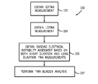
- a method in another embodiment, includes obtaining a short duration TWA differential measurement, and obtaining a long duration TWA differential measurement. The method also includes eliminating any data exceeding a first high differential limit from the long duration TWA measurement. Cardiac electrical instability is diagnosed if the short duration TWA differential measurement exceeds a second high differential limit or if the long duration TWA differential measurement exceeds a low differential limit. The method also includes performing a TWA burden analysis in order to obtain a degree of concern assessment.
- a system in yet another embodiment, includes a plurality of sensors; and a processor operatively connected to the plurality of sensors.
- the processor is configured to generate a cardiac electrical instability assessment based on a short duration TWA measurement and a long duration TWA measurement.
- FIG. 1 is a schematic illustration of a cardiac diagnostic/monitoring system operatively connected to a patient via a twelve lead system in accordance with an embodiment
- FIG. 2 is a PQRST complex of an electrocardiogram in accordance with an embodiment
- FIG. 3 shows two consecutive PQRST complexes that have been superimposed in accordance with an embodiment
- FIG. 4 is a flow chart in accordance with an embodiment
- FIG. 5 is a flow chart in accordance with an embodiment
- FIG. 6 is a flow chart in accordance with an embodiment
- FIG. 7 is a flow chart in accordance with an embodiment.
- a schematically represented cardiac diagnostic/monitoring system 6 is adapted measure an electrical signal generated by a patient's heart.
- the cardiac diagnostic/monitoring system 6 can be coupled to the patient 12 by an array of sensors or transducers.
- the array of sensors include a right arm electrode RA; a left arm electrode LA; chest electrodes V 1 , V 2 , V 3 , V 4 , V 5 and V 6 ; a right leg electrode RL; and a left electrode leg LL for acquiring a standard twelve lead, ten-electrode electrocardiogram (ECG) signal.
- ECG electrocardiogram
- the twelve ECG leads include leads I, II, V 1 , V 2 , V 3 , V 4 , V 5 and V 6 which are acquired directly from the patient leads, and leads III, aVR, aVL and aVF which are derived using Einthoven's law.
- the cardiac diagnostic/monitoring system 6 comprises a processor 8 configured to generate a patient diagnosis based on the measured cardiac electrical signals as will be described in detail hereinafter.
- an electrocardiogram (ECG) of a single heartbeat typically referred to as a PQRST complex is shown.
- the portion of the PQRST complex defined between reference points 14 and 16 is defined as the P-wave, and corresponds to activity in the atria.
- the portion of the PQRST complex defined between reference points 18 and 20 is defined as the QRS complex, and represents the electrical activation of the ventricles.
- the portion of the PQRST complex defined between reference points 22 and 24 is defined as the T-wave, and represents the electrical recovery or recharge phase of the ventricles.
- the portion of the PQRST complex defined between reference points 20 and 22 is defined as the ST segment.
- the portion of the PQRST complex defined between reference points 20 and 24 comprising both the ST segment and the T-wave will hereinafter be referred to as the ST-T segment.
- T-wave alternans is an electrophysiological phenomenon that is evident in the ECG as an alternating pattern of ST-T segment morphologies on consecutive beats.
- TWA T-wave alternans
- TWA is measured as the maximum differential between the ST-T segment of the PQRST complex 30 and the ST-T segment of the PQRST complex 32 .
- differential refers to the difference between two or more data points and is typically measured in microvolts.
- the TWA measurement for the consecutive PQRST complexes 30 , 32 may be defined as 5.0 microvolts. This TWA measurement can be compared with previously acquired research or test data in order to identify cardiac electrical instability.
- a user can identify specific portions of the PQRST complex 30 and the PQRST complex 32 to be evaluated.
- TWA is measured as the maximum differential between the PQRST complex 30 and the PQRST complex 32 as measured in the identified portions of the respective complexes 30 and 32 .
- the identified portions of the complexes 30 and 32 may comprise a specific point or a range of points to be evaluated.
- TWA tissue-to-emetic electrowetting
- Some methods for measuring TWA are more capable of identifying cardiac electrical instability than others.
- a clinical study comprising 681 patients was conducted and the method 100 (shown in FIG. 4 ) was validated. The clinical study will now be described in more detail.
- a first subset of patients with cardiac electrical instability is identifiable with a short duration high differential TWA measurement
- a second generally distinct subset of patients with cardiac electrical instability is identifiable with a long duration low differential TWA measurement.
- the method 100 assesses cardiac electrical instability based on two distinct TWA measurements in order to identify the greatest percentage of patients with cardiac electrical instability.
- a short duration TWA (SDTWA) measurement is a TWA measurement derived from 16 or fewer consecutive heartbeats
- a long duration TWA (LDTWA) measurement is a TWA measurement derived from 64 or more consecutive heartbeats.
- the term high differential should be defined to include differentials in excess of 40 microvolts, and the term low differential should be defined to include differentials below 10 microvolts. It will be appreciated by those skilled in the art that SDTWA is sometimes referred to as non-sustained TWA, and LDTWA is sometimes referred to as sustained TWA.
- the method 100 comprises steps 102 - 107 .
- one or more of the steps 102 - 107 may be performed by the processor 8 of the cardiac diagnostic/monitoring system 6 (shown in FIG. 1 ).
- a SDTWA measurement is obtained.
- a LDTWA measurement is obtained.
- a cardiac electrical instability assessment is obtained based on both the SDTWA measurement of step 102 and the LDTWA measurement of step 104 .
- a TWA burden analysis is performed. Having briefly described each step of the method 100 , the individual steps 102 - 107 will now be described in more detail.
- step 102 of the method 100 (shown in FIG. 4 ) will now be described in accordance with an embodiment.
- step 102 comprises steps 110 - 116 .
- one or more of the steps 110 - 116 may be performed by the processor 8 of the cardiac diagnostic/monitoring system 6 (shown in FIG. 1 ). It should be appreciated that the steps 110 - 116 need not necessarily be performed in the order shown.
- PQRST complex data pertaining to a plurality of sequential heartbeats is bifurcated into even beat data and odd beat data.
- a predetermined portion of the even beat data is extracted and averaged to produce an even beat average.
- the ST-T segments are extracted from the even beat data and are thereafter averaged.
- a predetermined portion of the odd beat data is extracted and averaged to produce an odd beat average.
- the ST-T segments are extracted from the odd beat data and are thereafter averaged.
- the even beat averages are compared with the odd beat averages. According to one embodiment, the step 116 comparison includes identifying the maximum difference between the even beat averages and the odd beat averages.
- step 104 of the method 100 (shown in FIG. 4 ) will now be described in accordance with an embodiment.
- step 104 comprises steps 108 - 116 .
- one or more of the steps 108 - 116 may be performed by the processor 8 of the cardiac diagnostic/monitoring system 6 (shown in FIG. 1 ). It should be appreciated that the steps 108 - 116 need not necessarily be performed in the order shown.
- Step 108 is an optional step that may be implemented to filter out or otherwise eliminate high differential data from the LDTWA measurement.
- the filtration may be performed in a variety of known ways such as with a low-pass filter or with an algorithm adapted to digitally eliminate any data exceeding a predefined high differential limit before the LDTWA measurement is performed.
- the process of filtering out the high differential data from the LDTWA measurement prevents this data from introducing imprecision into the LDTWA measurement. In other words, if the high differential data is not filtered, it could skew the resultant LDTWA measurement and yield an imprecise or misleading result.
- step 106 of the method 100 (shown in FIG. 4 ) will now be described in accordance with an embodiment.
- step 106 comprises steps 120 - 124 .
- one or more of the steps 120 - 124 may be performed by the processor 8 of the cardiac diagnostic/monitoring system 6 (shown in FIG. 1 ).
- step 120 it is determined if the SDTWA measurement obtained at step 102 (shown in FIG. 5 ) exceeds a predetermined high differential limit. According to one embodiment, step 120 determines if the SDTWA measurement exceeds 60 microvolts. At step 120 , it is also determined if the LDTWA measurement obtained at step 104 (shown in FIG. 6 ) exceeds a low differential limit. According to one embodiment, step 120 determines if the LDTWA measurement exceeds 5 microvolts. If, at step 120 , the SDTWA measurement exceeds the high differential limit or the LDTWA measurement exceeds the low differential limit, the algorithm proceeds to step 122 at which the patient is positively diagnosed for cardiac electrical instability. If, at step 120 , the SDTWA measurement does not exceed the high differential limit and the LDTWA measurement does not exceed the low differential limit, the algorithm proceeds to step 124 at which the patient is negatively diagnosed for cardiac electrical instability.
- step 107 of the method 100 will now be described in more detail.
- the TWA burden analysis of step 107 is optional and is adapted to provide a quantitative assessment along with each cardiac electrical instability diagnosis.
- the TWA burden analysis provides a degree of concern assessment that is intended to convey the seriousness of a given cardiac electrical instability diagnosis.
- the TWA burden analysis of step 107 may be performed by calculating the number of times the SDTWA measurement of step 102 exceeds a first predefined threshold (e.g., 60 microvolts); and the number of times the LDTWA measurement of step 104 exceeds a second predefined threshold (e.g., 5 microvolts).
- a first predefined threshold e.g. 60 microvolts
- a second predefined threshold e.g. 5 microvolts
- a second patient does not exceeds the 60 microvolt threshold during a SDTWA measurement and exceeds the 5 microvolt threshold one time during a LDTWA measurement. Both patients would receive a positive diagnosis for cardiac electrical instability at step 106 described in detail hereinabove with FIG. 7 ; however, the first patient would also receive a TWA burden analysis of five indicating a greater degree of concern as compared to the second patient having a TWA burden analysis of one.
- the TWA burden analysis of step 107 may be performed by measuring the duration or amount of time during which the SDTWA measurement of step 102 exceeds a first predefined threshold (e.g., 60 microvolts); and the amount of time during which the LDTWA measurement of step 104 exceeds a second predefined threshold (e.g., 5 microvolts).
- a first predefined threshold e.g. 60 microvolts
- a second predefined threshold e.g., 5 microvolts
- a second patient does not exceeds the 60 microvolt threshold during a SDTWA measurement and exceeds the 5 microvolt threshold for a period of one second during a LDTWA measurement. Both patients would receive a positive diagnosis for cardiac electrical instability at step 106 described in detail hereinabove with FIG. 7 ; however, the first patient would also receive a TWA burden analysis of five seconds indicating a greater degree of concern as compared to the second patient having a TWA burden analysis of one second.
Abstract
Description
Claims (21)
Priority Applications (1)
| Application Number | Priority Date | Filing Date | Title |
|---|---|---|---|
| US12/332,095 US8060192B2 (en) | 2008-12-10 | 2008-12-10 | Method and system for detecting T-wave alternans |
Applications Claiming Priority (1)
| Application Number | Priority Date | Filing Date | Title |
|---|---|---|---|
| US12/332,095 US8060192B2 (en) | 2008-12-10 | 2008-12-10 | Method and system for detecting T-wave alternans |
Publications (2)
| Publication Number | Publication Date |
|---|---|
| US20100145207A1 US20100145207A1 (en) | 2010-06-10 |
| US8060192B2 true US8060192B2 (en) | 2011-11-15 |
Family
ID=42231875
Family Applications (1)
| Application Number | Title | Priority Date | Filing Date |
|---|---|---|---|
| US12/332,095 Active 2029-11-01 US8060192B2 (en) | 2008-12-10 | 2008-12-10 | Method and system for detecting T-wave alternans |
Country Status (1)
| Country | Link |
|---|---|
| US (1) | US8060192B2 (en) |
Citations (14)
| Publication number | Priority date | Publication date | Assignee | Title |
|---|---|---|---|---|
| US5570696A (en) | 1994-01-26 | 1996-11-05 | Cambridge Heart, Inc. | Method and apparatus for assessing myocardial electrical stability |
| US5704365A (en) | 1994-11-14 | 1998-01-06 | Cambridge Heart, Inc. | Using related signals to reduce ECG noise |
| US5891045A (en) | 1996-07-17 | 1999-04-06 | Cambridge Heart, Inc. | Method and system for obtaining a localized cardiac measure |
| US5935082A (en) | 1995-01-26 | 1999-08-10 | Cambridge Heart, Inc. | Assessing cardiac electrical stability |
| US6169919B1 (en) | 1999-05-06 | 2001-01-02 | Beth Israel Deaconess Medical Center, Inc. | System and method for quantifying alternation in an electrocardiogram signal |
| US6453191B2 (en) | 2000-02-18 | 2002-09-17 | Cambridge Heart, Inc. | Automated interpretation of T-wave alternans results |
| US6668189B2 (en) | 2001-10-05 | 2003-12-23 | Ge Medical Systems Information Technologies, Inc. | Method and system for measuring T-wave alternans by alignment of alternating median beats to a cubic spline |
| US6735466B1 (en) | 1999-09-29 | 2004-05-11 | Cambridge Heart, Inc. | Analytical signal method for analysis of T-wave alternans |
| US6823213B1 (en) * | 2000-04-28 | 2004-11-23 | Medtronic, Inc. | Implantable medical device and method using integrated T-wave alternans analyzer |
| US7027857B2 (en) | 2003-02-14 | 2006-04-11 | The General Electric Company | Method and system for improved measurement of T-wave alternans |
| US7050846B2 (en) * | 1999-10-01 | 2006-05-23 | Cardiac Pacemakers, Inc. | Cardiac rhythm management system with arrhythmia prediction and prevention |
| US20060116596A1 (en) * | 2004-12-01 | 2006-06-01 | Xiaohong Zhou | Method and apparatus for detection and monitoring of T-wave alternans |
| US7221976B2 (en) * | 2003-06-10 | 2007-05-22 | Jean Philippe Couderc | Analysis of the alternans cycle to cycle and/or the variability of the ventricular repolarization wave in an ECG signal |
| US20090192398A1 (en) * | 2007-10-12 | 2009-07-30 | Xiaohong Zhou | Method and apparatus for monitoring t-wave alternans |
-
2008
- 2008-12-10 US US12/332,095 patent/US8060192B2/en active Active
Patent Citations (15)
| Publication number | Priority date | Publication date | Assignee | Title |
|---|---|---|---|---|
| US5713367A (en) | 1994-01-26 | 1998-02-03 | Cambridge Heart, Inc. | Measuring and assessing cardiac electrical stability |
| US5570696A (en) | 1994-01-26 | 1996-11-05 | Cambridge Heart, Inc. | Method and apparatus for assessing myocardial electrical stability |
| US5704365A (en) | 1994-11-14 | 1998-01-06 | Cambridge Heart, Inc. | Using related signals to reduce ECG noise |
| US5935082A (en) | 1995-01-26 | 1999-08-10 | Cambridge Heart, Inc. | Assessing cardiac electrical stability |
| US5891045A (en) | 1996-07-17 | 1999-04-06 | Cambridge Heart, Inc. | Method and system for obtaining a localized cardiac measure |
| US6169919B1 (en) | 1999-05-06 | 2001-01-02 | Beth Israel Deaconess Medical Center, Inc. | System and method for quantifying alternation in an electrocardiogram signal |
| US6735466B1 (en) | 1999-09-29 | 2004-05-11 | Cambridge Heart, Inc. | Analytical signal method for analysis of T-wave alternans |
| US7050846B2 (en) * | 1999-10-01 | 2006-05-23 | Cardiac Pacemakers, Inc. | Cardiac rhythm management system with arrhythmia prediction and prevention |
| US6453191B2 (en) | 2000-02-18 | 2002-09-17 | Cambridge Heart, Inc. | Automated interpretation of T-wave alternans results |
| US6823213B1 (en) * | 2000-04-28 | 2004-11-23 | Medtronic, Inc. | Implantable medical device and method using integrated T-wave alternans analyzer |
| US6668189B2 (en) | 2001-10-05 | 2003-12-23 | Ge Medical Systems Information Technologies, Inc. | Method and system for measuring T-wave alternans by alignment of alternating median beats to a cubic spline |
| US7027857B2 (en) | 2003-02-14 | 2006-04-11 | The General Electric Company | Method and system for improved measurement of T-wave alternans |
| US7221976B2 (en) * | 2003-06-10 | 2007-05-22 | Jean Philippe Couderc | Analysis of the alternans cycle to cycle and/or the variability of the ventricular repolarization wave in an ECG signal |
| US20060116596A1 (en) * | 2004-12-01 | 2006-06-01 | Xiaohong Zhou | Method and apparatus for detection and monitoring of T-wave alternans |
| US20090192398A1 (en) * | 2007-10-12 | 2009-07-30 | Xiaohong Zhou | Method and apparatus for monitoring t-wave alternans |
Also Published As
| Publication number | Publication date |
|---|---|
| US20100145207A1 (en) | 2010-06-10 |
Similar Documents
| Publication | Publication Date | Title |
|---|---|---|
| CN107072545B (en) | Electrocardiogram data analysis method and system for rapid diagnosis | |
| US8024030B2 (en) | System and method for analyzing an electrocardiogram signal | |
| US9693704B2 (en) | RMS electrocardiography system and method | |
| US6607480B1 (en) | Evaluation system for obtaining diagnostic information from the signals and data of medical sensor systems | |
| WO2009077915A1 (en) | Automated identification of culprit coronary artery using anatomically oriented ecg data display | |
| WO2009088627A1 (en) | System, method and device for predicting sudden cardiac death risk | |
| JP2013517083A (en) | Identification of the causal coronary artery using anatomically oriented ECG data from the expanded lead set | |
| JP2010535570A (en) | Automatic identification of the responsible coronary artery | |
| Berbari et al. | An introduction to high-resolution ECG recordings of cardiac late potentials | |
| US20180125384A1 (en) | Data processing apparatus for assessing a condition of a myocardium | |
| RU2598049C2 (en) | Automated identification of location of occlusion in infarct-related coronary artery | |
| EP1219236A2 (en) | System and method for detecting new left branch bundle block for accelerating treatment of acute myocardial infarction | |
| US4987901A (en) | Method and apparatus for selecting a physiologically standardized sensor of a multi-sensor electrocardiogram sensor set | |
| CN107530020A (en) | Method and system for the heart ischemia detection based on ECG | |
| JP3137900B2 (en) | Apparatus for collecting and processing electrocardiogram signals | |
| Matveev et al. | Possibilities of signal-averaged orthogonal and vector electrocardiography for locating and size evaluation of acute myocardial infarction with ST-elevation | |
| US20040162498A1 (en) | Method and system for improved measurement of T-wave alternans | |
| US8060192B2 (en) | Method and system for detecting T-wave alternans | |
| Lázaro et al. | Feasibility of long-term daily life electrocardiogram monitoring based on a wearable armband device | |
| Sbrollini et al. | Athria: a new adaptive threshold identification algorithm for electrocardiographic p waves | |
| González et al. | A spatial study of the ST segment | |
| Al Touma et al. | Detection of cardiovascular abnormalities through 5-lead system algorithm | |
| Kot et al. | Analysis of the Biological Signal for Automated Diagnostics | |
| Guzmán et al. | Diagnosis of non-type I Brugada syndrome patients by vectorcardiographic measurements | |
| Sánchez-Carballo et al. | Single Reference Segmentation to Estimate T-Wave Alternans |
Legal Events
| Date | Code | Title | Description |
|---|---|---|---|
| AS | Assignment |
Owner name: GENERAL ELECTRIC COMPANY,NEW YORK Free format text: ASSIGNMENT OF ASSIGNORS INTEREST;ASSIGNORS:ROWLANDSON, GORDON IAN;KAISER, WILLI;XUE, JOEL QUIZHEN;SIGNING DATES FROM 20081125 TO 20081126;REEL/FRAME:022004/0418 Owner name: GENERAL ELECTRIC COMPANY, NEW YORK Free format text: ASSIGNMENT OF ASSIGNORS INTEREST;ASSIGNORS:ROWLANDSON, GORDON IAN;KAISER, WILLI;XUE, JOEL QUIZHEN;SIGNING DATES FROM 20081125 TO 20081126;REEL/FRAME:022004/0418 |
|
| STCF | Information on status: patent grant |
Free format text: PATENTED CASE |
|
| CC | Certificate of correction | ||
| FPAY | Fee payment |
Year of fee payment: 4 |
|
| MAFP | Maintenance fee payment |
Free format text: PAYMENT OF MAINTENANCE FEE, 8TH YEAR, LARGE ENTITY (ORIGINAL EVENT CODE: M1552); ENTITY STATUS OF PATENT OWNER: LARGE ENTITY Year of fee payment: 8 |
|
| MAFP | Maintenance fee payment |
Free format text: PAYMENT OF MAINTENANCE FEE, 12TH YEAR, LARGE ENTITY (ORIGINAL EVENT CODE: M1553); ENTITY STATUS OF PATENT OWNER: LARGE ENTITY Year of fee payment: 12 |