US7913788B1 - Integrated energy storage and rear suspension assembly - Google Patents
Integrated energy storage and rear suspension assembly Download PDFInfo
- Publication number
- US7913788B1 US7913788B1 US12/702,527 US70252710A US7913788B1 US 7913788 B1 US7913788 B1 US 7913788B1 US 70252710 A US70252710 A US 70252710A US 7913788 B1 US7913788 B1 US 7913788B1
- Authority
- US
- United States
- Prior art keywords
- cross member
- face sheet
- assembly
- sandwich panel
- vehicle
- Prior art date
- Legal status (The legal status is an assumption and is not a legal conclusion. Google has not performed a legal analysis and makes no representation as to the accuracy of the status listed.)
- Expired - Fee Related
Links
Images


Classifications
-
- B—PERFORMING OPERATIONS; TRANSPORTING
- B60—VEHICLES IN GENERAL
- B60K—ARRANGEMENT OR MOUNTING OF PROPULSION UNITS OR OF TRANSMISSIONS IN VEHICLES; ARRANGEMENT OR MOUNTING OF PLURAL DIVERSE PRIME-MOVERS IN VEHICLES; AUXILIARY DRIVES FOR VEHICLES; INSTRUMENTATION OR DASHBOARDS FOR VEHICLES; ARRANGEMENTS IN CONNECTION WITH COOLING, AIR INTAKE, GAS EXHAUST OR FUEL SUPPLY OF PROPULSION UNITS IN VEHICLES
- B60K1/00—Arrangement or mounting of electrical propulsion units
- B60K1/04—Arrangement or mounting of electrical propulsion units of the electric storage means for propulsion
-
- B—PERFORMING OPERATIONS; TRANSPORTING
- B60—VEHICLES IN GENERAL
- B60K—ARRANGEMENT OR MOUNTING OF PROPULSION UNITS OR OF TRANSMISSIONS IN VEHICLES; ARRANGEMENT OR MOUNTING OF PLURAL DIVERSE PRIME-MOVERS IN VEHICLES; AUXILIARY DRIVES FOR VEHICLES; INSTRUMENTATION OR DASHBOARDS FOR VEHICLES; ARRANGEMENTS IN CONNECTION WITH COOLING, AIR INTAKE, GAS EXHAUST OR FUEL SUPPLY OF PROPULSION UNITS IN VEHICLES
- B60K15/00—Arrangement in connection with fuel supply of combustion engines or other fuel consuming energy converters, e.g. fuel cells; Mounting or construction of fuel tanks
- B60K15/03—Fuel tanks
- B60K15/063—Arrangement of tanks
-
- B—PERFORMING OPERATIONS; TRANSPORTING
- B60—VEHICLES IN GENERAL
- B60L—PROPULSION OF ELECTRICALLY-PROPELLED VEHICLES; SUPPLYING ELECTRIC POWER FOR AUXILIARY EQUIPMENT OF ELECTRICALLY-PROPELLED VEHICLES; ELECTRODYNAMIC BRAKE SYSTEMS FOR VEHICLES IN GENERAL; MAGNETIC SUSPENSION OR LEVITATION FOR VEHICLES; MONITORING OPERATING VARIABLES OF ELECTRICALLY-PROPELLED VEHICLES; ELECTRIC SAFETY DEVICES FOR ELECTRICALLY-PROPELLED VEHICLES
- B60L50/00—Electric propulsion with power supplied within the vehicle
- B60L50/50—Electric propulsion with power supplied within the vehicle using propulsion power supplied by batteries or fuel cells
- B60L50/60—Electric propulsion with power supplied within the vehicle using propulsion power supplied by batteries or fuel cells using power supplied by batteries
- B60L50/61—Electric propulsion with power supplied within the vehicle using propulsion power supplied by batteries or fuel cells using power supplied by batteries by batteries charged by engine-driven generators, e.g. series hybrid electric vehicles
-
- B—PERFORMING OPERATIONS; TRANSPORTING
- B60—VEHICLES IN GENERAL
- B60L—PROPULSION OF ELECTRICALLY-PROPELLED VEHICLES; SUPPLYING ELECTRIC POWER FOR AUXILIARY EQUIPMENT OF ELECTRICALLY-PROPELLED VEHICLES; ELECTRODYNAMIC BRAKE SYSTEMS FOR VEHICLES IN GENERAL; MAGNETIC SUSPENSION OR LEVITATION FOR VEHICLES; MONITORING OPERATING VARIABLES OF ELECTRICALLY-PROPELLED VEHICLES; ELECTRIC SAFETY DEVICES FOR ELECTRICALLY-PROPELLED VEHICLES
- B60L50/00—Electric propulsion with power supplied within the vehicle
- B60L50/50—Electric propulsion with power supplied within the vehicle using propulsion power supplied by batteries or fuel cells
- B60L50/60—Electric propulsion with power supplied within the vehicle using propulsion power supplied by batteries or fuel cells using power supplied by batteries
- B60L50/66—Arrangements of batteries
-
- B—PERFORMING OPERATIONS; TRANSPORTING
- B60—VEHICLES IN GENERAL
- B60K—ARRANGEMENT OR MOUNTING OF PROPULSION UNITS OR OF TRANSMISSIONS IN VEHICLES; ARRANGEMENT OR MOUNTING OF PLURAL DIVERSE PRIME-MOVERS IN VEHICLES; AUXILIARY DRIVES FOR VEHICLES; INSTRUMENTATION OR DASHBOARDS FOR VEHICLES; ARRANGEMENTS IN CONNECTION WITH COOLING, AIR INTAKE, GAS EXHAUST OR FUEL SUPPLY OF PROPULSION UNITS IN VEHICLES
- B60K1/00—Arrangement or mounting of electrical propulsion units
- B60K1/04—Arrangement or mounting of electrical propulsion units of the electric storage means for propulsion
- B60K2001/0405—Arrangement or mounting of electrical propulsion units of the electric storage means for propulsion characterised by their position
- B60K2001/0438—Arrangement under the floor
-
- B—PERFORMING OPERATIONS; TRANSPORTING
- B60—VEHICLES IN GENERAL
- B60K—ARRANGEMENT OR MOUNTING OF PROPULSION UNITS OR OF TRANSMISSIONS IN VEHICLES; ARRANGEMENT OR MOUNTING OF PLURAL DIVERSE PRIME-MOVERS IN VEHICLES; AUXILIARY DRIVES FOR VEHICLES; INSTRUMENTATION OR DASHBOARDS FOR VEHICLES; ARRANGEMENTS IN CONNECTION WITH COOLING, AIR INTAKE, GAS EXHAUST OR FUEL SUPPLY OF PROPULSION UNITS IN VEHICLES
- B60K1/00—Arrangement or mounting of electrical propulsion units
- B60K1/04—Arrangement or mounting of electrical propulsion units of the electric storage means for propulsion
- B60K2001/0455—Removal or replacement of the energy storages
- B60K2001/0472—Removal or replacement of the energy storages from below
-
- B—PERFORMING OPERATIONS; TRANSPORTING
- B60—VEHICLES IN GENERAL
- B60K—ARRANGEMENT OR MOUNTING OF PROPULSION UNITS OR OF TRANSMISSIONS IN VEHICLES; ARRANGEMENT OR MOUNTING OF PLURAL DIVERSE PRIME-MOVERS IN VEHICLES; AUXILIARY DRIVES FOR VEHICLES; INSTRUMENTATION OR DASHBOARDS FOR VEHICLES; ARRANGEMENTS IN CONNECTION WITH COOLING, AIR INTAKE, GAS EXHAUST OR FUEL SUPPLY OF PROPULSION UNITS IN VEHICLES
- B60K15/00—Arrangement in connection with fuel supply of combustion engines or other fuel consuming energy converters, e.g. fuel cells; Mounting or construction of fuel tanks
- B60K15/03—Fuel tanks
- B60K15/063—Arrangement of tanks
- B60K2015/0638—Arrangement of tanks the fuel tank is arranged in the rear of the vehicle
-
- Y—GENERAL TAGGING OF NEW TECHNOLOGICAL DEVELOPMENTS; GENERAL TAGGING OF CROSS-SECTIONAL TECHNOLOGIES SPANNING OVER SEVERAL SECTIONS OF THE IPC; TECHNICAL SUBJECTS COVERED BY FORMER USPC CROSS-REFERENCE ART COLLECTIONS [XRACs] AND DIGESTS
- Y02—TECHNOLOGIES OR APPLICATIONS FOR MITIGATION OR ADAPTATION AGAINST CLIMATE CHANGE
- Y02T—CLIMATE CHANGE MITIGATION TECHNOLOGIES RELATED TO TRANSPORTATION
- Y02T10/00—Road transport of goods or passengers
- Y02T10/60—Other road transportation technologies with climate change mitigation effect
- Y02T10/62—Hybrid vehicles
-
- Y—GENERAL TAGGING OF NEW TECHNOLOGICAL DEVELOPMENTS; GENERAL TAGGING OF CROSS-SECTIONAL TECHNOLOGIES SPANNING OVER SEVERAL SECTIONS OF THE IPC; TECHNICAL SUBJECTS COVERED BY FORMER USPC CROSS-REFERENCE ART COLLECTIONS [XRACs] AND DIGESTS
- Y02—TECHNOLOGIES OR APPLICATIONS FOR MITIGATION OR ADAPTATION AGAINST CLIMATE CHANGE
- Y02T—CLIMATE CHANGE MITIGATION TECHNOLOGIES RELATED TO TRANSPORTATION
- Y02T10/00—Road transport of goods or passengers
- Y02T10/60—Other road transportation technologies with climate change mitigation effect
- Y02T10/70—Energy storage systems for electromobility, e.g. batteries
-
- Y—GENERAL TAGGING OF NEW TECHNOLOGICAL DEVELOPMENTS; GENERAL TAGGING OF CROSS-SECTIONAL TECHNOLOGIES SPANNING OVER SEVERAL SECTIONS OF THE IPC; TECHNICAL SUBJECTS COVERED BY FORMER USPC CROSS-REFERENCE ART COLLECTIONS [XRACs] AND DIGESTS
- Y02—TECHNOLOGIES OR APPLICATIONS FOR MITIGATION OR ADAPTATION AGAINST CLIMATE CHANGE
- Y02T—CLIMATE CHANGE MITIGATION TECHNOLOGIES RELATED TO TRANSPORTATION
- Y02T10/00—Road transport of goods or passengers
- Y02T10/60—Other road transportation technologies with climate change mitigation effect
- Y02T10/7072—Electromobility specific charging systems or methods for batteries, ultracapacitors, supercapacitors or double-layer capacitors
Definitions
- the present invention relates generally to hybrid electric vehicles and more particularly to systems for mounting energy storage assemblies into the vehicle.
- hybrid vehicles that is vehicles that employ more than one source of energy to operate.
- a common type of hybrid vehicle is the hybrid electric vehicle that includes a propulsion motor and an internal combustion engine.
- additional systems and assemblies must be packaged in the vehicle as compared to a conventional vehicle.
- these systems are packaged in the vehicle in a compact, light weight, cost effective, and easy to assemble manner.
- An embodiment contemplates an integrated energy storage and rear suspension assembly for use with a vehicle having a body including a rear body cavity and an adjacent forward body cavity, with the rear and forward body cavities located between a pair of frame rails.
- the assembly includes a rear fuel tank/suspension module, a battery support assembly and a structural joining plate.
- the rear fuel tank/suspension module includes a rear sandwich panel, a fuel tank assembly mounted on the rear sandwich panel, a rear cross member mounted on and extending laterally across a rear edge of the rear sandwich panel, a front cross member mounted on and extending laterally across a front edge of the rear sandwich panel, and a pair of lower control arms, each mounted to and extending from opposed ends of the rear cross member and the front cross member, with the rear fuel tank/suspension module sliding into the rear body cavity.
- the battery support assembly includes a propulsion battery mounted on a front sandwich plate, the front sandwich plate having an upper face sheet adjacent to the propulsion battery, a lower face sheet spaced from the upper face sheet and a core connecting the upper face sheet to the lower face sheet, with the lower face sheet having a smooth lower surface, and with the battery support assembly sliding into the forward body cavity.
- the structural joining plate connects to and secures a rear edge of the front sandwich panel to the front edge of the rear sandwich panel.
- an advantage of an embodiment is that the integrated energy storage and rear suspension assembly has a relatively low mass for its structural support capabilities, and provides for efficient packaging of the energy storage assemblies into the vehicle body. Moreover, this assembly has efficient aerodynamic performance since it presents a smooth, flush surface with the underside of the vehicle body. In addition, this assembly is relatively easy to assemble to the vehicle and allows for ease of removal for servicing.
- the cored, sandwich material used for the front and rear sandwich panels contribute to providing these advantages in mounting and supporting the propulsion battery and fuel tank assembly, while also providing increased body stiffness. The sandwich panels may also provide additional protection during side and rear vehicle impacts.
- a portion of the rear suspension is supported by the integrated energy storage and rear suspension assembly, further improving overall packaging efficiency of this assembly in the vehicle body.
- FIG. 1 is a perspective view looking down on an integrated energy storage and rear suspension assembly.
- FIG. 2 is a perspective view looking up at the assembly of FIG. 1 .
- FIG. 3 is a schematic, section view of a front sandwich panel.
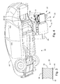
- FIG. 4 is a perspective view looking up at a portion of a vehicle, with the integrated energy storage and rear suspension assembly shown before assembly to the vehicle body.
- FIG. 5 is a perspective view similar to FIG. 4 , but illustrating the rear fuel tank/suspension module mounted to the vehicle body and the battery/support assembly ready for assembly.
- FIG. 6 is a perspective view similar to FIG. 4 , but illustrating the integrated energy storage and rear suspension assembly assembled to the vehicle body.
- the assembly 20 includes a battery support assembly 22 and a rear fuel tank/suspension module 24 .
- the battery support assembly 22 includes a propulsion battery pack 26 (a portion of which is shown), which is mounted on a front sandwich panel 28 .
- the battery pack 26 stores energy for driving an electric motor (not shown).
- the rear fuel tank/support module 24 includes a fuel tank assembly 30 that is mounted on a rear sandwich panel 32 .
- a rear cross member 34 is also mounted to the rear sandwich panel 32 just behind the fuel tank assembly 30 and extends across the width of the panel 32 .
- a front cross member 36 mounts to the rear sandwich panel 32 between the fuel tank assembly 30 and the propulsion battery pack 26 and also extends across the width of the panel 32 .
- a pair of lower control arms 38 extend laterally outward from the rear and front cross members 34 , 36 .
- Each lower control arm 38 includes a front flange 40 that flexibly mounts to the front cross member 36 and a rear flange 42 that flexibly mounts to the rear cross member 34 .
- the lower control arms 38 are part of the rear suspension of the vehicle.
- a structural joining plate 44 connects between a bottom face 46 of the front sandwich panel 28 and a bottom face 48 of the rear sandwich panel 32 .
- the joining plate 44 secures and structurally holds the two panels together.
- the bottom of the joining plate 44 , as well as the bottom faces 46 , 48 of the panels 28 , 32 are preferably flat and smooth to reduce aerodynamic drag on the vehicle.
- FIG. 3 illustrates a cross section through a portion of the front sandwich panel 28 .
- the construction of the rear sandwich panel 32 can be essentially the same as the front and so will not be shown in more detail.
- the front sandwich panel 28 includes an upper face sheet 50 , which may be made of steel or other high strength material, a lower face sheet 52 , which may be made of steel or other high strength material, and a core 54 connecting the upper face sheet 50 to the lower face sheet 52 .
- the core 54 preferably has a low density in order to minimize the weight and may be, for example, a foam core, a urethane mid-density foam, a Kevlar honeycomb, an aluminum honeycomb or balsa wood.
- This arrangement of the higher strength upper and lower face sheets 50 , 52 with a light weight core provides a high strength to weight ratio, a compact support structure, smooth bottom face 46 for good aerodynamic properties, and allows the structure to handle bending, shear and torsion loads introduced into the energy storage and rear suspension assembly 20 .
- the energy storage systems are supported in vertical bending, side and rear impact loads are accounted for, rear suspension loads are supported, and global body loads are accounted for while minimizing the overall mass.
- FIGS. 4-6 illustrate a portion of the assembly process for installing the integrated energy storage and rear suspension assembly 20 into a body 58 of a vehicle 60 .
- the body includes a rear cavity 59 sized to receive the fuel tank/suspension module 24 and a forward cavity 61 sized to receive the battery support assembly 22 .
- the battery support assembly 22 and the fuel tank/suspension module 24 are each assembled. While the two are shown together in FIG. 4 , that is just for illustrative purposes.
- the fuel tank/rear suspension module 24 is lifted into the body 58 from below, as is shown in FIG. 5 .
- the front cross member 36 and the rear cross member 34 are secured to the body 58 , which may include securing them to a pair of longitudinally extending frame rails 62 and laterally extending suspension cross member 66 (the cross member 66 visible in FIG. 4 ).
- the fuel tank assembly 30 as well as the lower control arms are now securely affixed to the vehicle 60 .
- the front sandwich panel 28 may be secured to the frame rails 62 , a laterally extending forward cross-car structural member 68 and the suspension cross member 66 (the members 66 , 68 visible in FIG. 4 ).
- the front sandwich panel 28 may be mounted to the body 58 using, for example, bolts and removable sealer/adhesive. This will seal the propulsion battery pack from the elements, while still allowing it to be removed for service.
- the structural joining plate 44 is then mounted to the front and rear composite panels 28 , 32 at the suspension cross member 66 to secure the two panels 28 , 32 together.
Abstract
Description
Claims (17)
Priority Applications (2)
| Application Number | Priority Date | Filing Date | Title |
|---|---|---|---|
| US12/702,527 US7913788B1 (en) | 2010-02-09 | 2010-02-09 | Integrated energy storage and rear suspension assembly |
| DE102011009987.5A DE102011009987B4 (en) | 2010-02-09 | 2011-02-01 | Integrated energy storage and rear suspension assembly and vehicle |
Applications Claiming Priority (1)
| Application Number | Priority Date | Filing Date | Title |
|---|---|---|---|
| US12/702,527 US7913788B1 (en) | 2010-02-09 | 2010-02-09 | Integrated energy storage and rear suspension assembly |
Publications (1)
| Publication Number | Publication Date |
|---|---|
| US7913788B1 true US7913788B1 (en) | 2011-03-29 |
Family
ID=43769773
Family Applications (1)
| Application Number | Title | Priority Date | Filing Date |
|---|---|---|---|
| US12/702,527 Expired - Fee Related US7913788B1 (en) | 2010-02-09 | 2010-02-09 | Integrated energy storage and rear suspension assembly |
Country Status (2)
| Country | Link |
|---|---|
| US (1) | US7913788B1 (en) |
| DE (1) | DE102011009987B4 (en) |
Cited By (46)
| Publication number | Priority date | Publication date | Assignee | Title |
|---|---|---|---|---|
| US20100307848A1 (en) * | 2009-06-09 | 2010-12-09 | Fuji Jukogyo Kabushiki Kaisha | Battery mounting structure for vehicle |
| US20110168461A1 (en) * | 2010-01-14 | 2011-07-14 | Dr. Ing. H.C.F. Porsche Aktiengesellschaft | Battery system and motor vehicle |
| US20110240386A1 (en) * | 2010-04-05 | 2011-10-06 | Coda Automotive, Inc. | Electric vehicle with structurally integrated components |
| US20110253467A1 (en) * | 2010-04-16 | 2011-10-20 | Liebherr-Hydraulikbagger Gmbh | Construction Machine or Transfer Apparatus |
| US20120043147A1 (en) * | 2010-08-20 | 2012-02-23 | GM Global Technology Operations LLC | Energy storage arrangement in the floor area of a vehicle |
| CN102490593A (en) * | 2011-12-08 | 2012-06-13 | 南京大学 | Hydrogen fuel cell electric vehicle |
| US20130057025A1 (en) * | 2009-10-06 | 2013-03-07 | Renault S.A.S. | Impact protection device for an underbody-mounted member of a motor vehicle |
| WO2013041937A1 (en) * | 2011-09-20 | 2013-03-28 | Toyota Jidosha Kabushiki Kaisha | Vehicular battery mounting structure |
| US20130333962A1 (en) * | 2011-05-19 | 2013-12-19 | Lg Chem, Ltd. | Battery pack with high structural reliability |
| CN103619623A (en) * | 2011-06-20 | 2014-03-05 | 株式会社丰田自动织机 | Vehicle battery unit installation apparatus |
| US20140191498A1 (en) * | 2013-01-09 | 2014-07-10 | Erin Marie SHIPP | Truck fuel tank system for improved crashworthiness |
| FR3001185A1 (en) * | 2013-01-24 | 2014-07-25 | Courb | Terrestrial vehicle i.e. light electric car, has sealing packing interposed between floor and part of upper edge such that floor, frame, and sealing packing contribute to form watertight bell that caps electrical supply unit |
| US8950536B2 (en) | 2011-12-21 | 2015-02-10 | Ford Global Technologies, Llc | Modular battery assembly support and seals |
| US20160114672A1 (en) * | 2014-10-23 | 2016-04-28 | Mitsubishi Jidosha Kogyo Kabushiki Kaisha | Arrangement structure of canister in vehicle |
| US9381798B2 (en) | 2010-01-14 | 2016-07-05 | Dr. Ing. H.C.F. Porsche Aktiengesellschaft | Battery system and motor vehicle |
| DE102015205413A1 (en) | 2015-03-25 | 2016-09-29 | Deutsches Zentrum für Luft- und Raumfahrt e.V. | Carrying structure and vehicle |
| US9511657B2 (en) | 2011-09-08 | 2016-12-06 | GM Global Technology Operations LLC | Replaceable battery module for an electric vehicle |
| US20170149035A1 (en) * | 2015-03-16 | 2017-05-25 | Thunder Power Hong Kong Ltd. | Battery pack of electric vehicle, electric vehicle chassis and method for replacing battery modules |
| US9758030B2 (en) | 2016-02-09 | 2017-09-12 | NextEv USA, Inc. | Replaceable battery assembly having a latching mechanism |
| US9937781B1 (en) | 2016-12-19 | 2018-04-10 | GM Global Technology Operations LLC | Battery pack mounting architecture with shear plate for electric drive motor vehicles |
| US9963028B1 (en) | 2017-02-21 | 2018-05-08 | Ford Global Technologies, Llc | Battery support structure for electrified vehicle |
| US10000328B1 (en) | 2017-05-11 | 2018-06-19 | Robson Forensic, Inc. | Vehicle fuel tank for improved crashworthiness |
| US10017037B2 (en) * | 2016-02-09 | 2018-07-10 | Nio Usa, Inc. | Vehicle having a battery pack directly attached to the cross rails of a frame structure |
| CN109004132A (en) * | 2018-07-26 | 2018-12-14 | 北京博简复才技术咨询有限公司 | A method of battery pack is improved using composite sandwich plate structure |
| DE102018200329A1 (en) | 2018-01-11 | 2019-07-11 | Ford Global Technologies, Llc | Chassis device of an electrically driven motor vehicle |
| US10461383B2 (en) | 2017-08-07 | 2019-10-29 | Ford Global Technologies, Llc | Battery enclosure having a composite structure with a coolant channel |
| US10549620B2 (en) * | 2016-09-07 | 2020-02-04 | Thunder Power Electric Vehicle Limited | Profiles in the floor section |
| CN111051104A (en) * | 2017-11-09 | 2020-04-21 | 宝马股份公司 | Method for integrating a high-voltage accumulator into a support structure of a motor vehicle, and motor vehicle |
| US10787203B2 (en) | 2018-01-03 | 2020-09-29 | Ford Global Technologies, Llc | Hybrid energy storage and delivery devices for hybrid electric vehicles |
| US20210078399A1 (en) * | 2018-06-14 | 2021-03-18 | Daniel REMON RODRIGUEZ | Energy storage system for vehicles |
| US11046192B2 (en) * | 2017-12-31 | 2021-06-29 | Hyliion Inc. | Electric vehicle energy store with fuel tank form factor and mounting configuration |
| JP2021109593A (en) * | 2020-01-14 | 2021-08-02 | トヨタ自動車株式会社 | Vehicle rear structure of electric vehicle |
| US11121427B1 (en) | 2019-01-25 | 2021-09-14 | Julian Enrique Bustamante Laparra | Stabilizing electric battery system for vehicles |
| WO2021185632A1 (en) * | 2020-03-19 | 2021-09-23 | Mubea Carbo Tech Gmbh | Protecting member for a battery structure of an electric vehicle |
| US11155149B2 (en) | 2019-08-08 | 2021-10-26 | Hyundai Motor Company | Battery and fuel tank arrangement structure of hybrid vehicle |
| US11161400B2 (en) * | 2018-07-18 | 2021-11-02 | Toyota Jidosha Kabushiki Kaisha | Vehicle rear structure |
| US11214137B2 (en) * | 2017-01-04 | 2022-01-04 | Shape Corp. | Vehicle battery tray structure with nodal modularity |
| US11267326B2 (en) * | 2019-06-28 | 2022-03-08 | Toyota Jidosha Kabushiki Kaisha | Vehicle lower-part structure |
| US11292325B2 (en) * | 2017-05-30 | 2022-04-05 | Flet Gmbh | Electric car |
| US11352062B2 (en) | 2012-12-21 | 2022-06-07 | Dr. Ing. H. C. F. Porsche Ag | Subframe for holding an electric energy accumulator in a motor vehicle |
| EP4063160A1 (en) * | 2021-03-22 | 2022-09-28 | Suzuki Motor Corporation | Lower cover structure for a vehicle |
| CN115214333A (en) * | 2022-03-31 | 2022-10-21 | 长城汽车股份有限公司 | Middle structure of lower vehicle body and vehicle |
| US20230031771A1 (en) * | 2021-07-29 | 2023-02-02 | Ford Global Technologies, Llc | Support structures for vehicle underbody mounted battery packs |
| US11597577B2 (en) | 2017-05-11 | 2023-03-07 | Robson Forensic, Inc. | Vehicle fuel tank for improved crashworthiness |
| DE102022111424B3 (en) | 2022-05-09 | 2023-06-22 | Dr. Ing. H.C. F. Porsche Aktiengesellschaft | Middle floor module for a motor vehicle, corresponding motor vehicle and method for the production thereof |
| US11780314B2 (en) | 2019-07-23 | 2023-10-10 | Hyundai Motor Company | Hybrid vehicle having improved arrangement structure |
Families Citing this family (7)
| Publication number | Priority date | Publication date | Assignee | Title |
|---|---|---|---|---|
| DE102011000482B4 (en) * | 2011-02-03 | 2023-09-28 | Dr. Ing. H.C. F. Porsche Aktiengesellschaft | motor vehicle |
| DE102012010897C5 (en) | 2012-06-01 | 2017-08-03 | Volkswagen Aktiengesellschaft | Battery box and vehicle comprising a battery box |
| DE102012112966A1 (en) * | 2012-12-21 | 2014-06-26 | Dr. Ing. H.C. F. Porsche Aktiengesellschaft | Subframe for receiving an electrical energy storage in a motor vehicle |
| DE102017007408B4 (en) * | 2017-08-04 | 2021-12-09 | Audi Ag | Motor vehicle with a memory device and memory device for a motor vehicle |
| DE102018222459A1 (en) | 2018-12-20 | 2020-06-25 | Audi Ag | Method for providing a battery arrangement for a motor vehicle and motor vehicle |
| DE102019101377A1 (en) * | 2019-01-21 | 2020-07-23 | Bayerische Motoren Werke Aktiengesellschaft | Axle carrier of a two-track vehicle with a shear field formed by an extruded profile |
| CN111038588B (en) * | 2019-12-27 | 2021-08-20 | 长城汽车股份有限公司 | Rear auxiliary frame assembly |
Citations (45)
| Publication number | Priority date | Publication date | Assignee | Title |
|---|---|---|---|---|
| US4593786A (en) * | 1982-05-03 | 1986-06-10 | John Tate | Self-contained power supply and support therefor |
| US5392873A (en) * | 1992-01-22 | 1995-02-28 | Honda Giken Kogyo Kabushiki Kaisha | Structure for securing batteries used in an electric vehicle |
| US5501289A (en) * | 1993-01-22 | 1996-03-26 | Nissan Motor Co., Ltd. | Floor structure of electric vehicle |
| US5516599A (en) * | 1992-09-15 | 1996-05-14 | Electric Fuel (E.F.L.) Ltd. | Means for storage and transportation of electric fuel |
| US5518272A (en) * | 1993-12-28 | 1996-05-21 | Honda Giken Kogyo Kabushiki Kaisha | Fuel bomb mounting structure for automobile |
| US5702125A (en) * | 1994-08-17 | 1997-12-30 | Honda Giken Kogyo Kabushiki Kaisha | Arrangement of disposition of canister in vehicle |
| US5924734A (en) * | 1996-05-09 | 1999-07-20 | Honda Giken Kogyo Kabushiki Kaisha | Fuel cylinder mounting structure in motorcar |
| US5948298A (en) * | 1996-04-26 | 1999-09-07 | Ford Global Technologies, Inc. | Battery heating system |
| US5992885A (en) * | 1996-05-09 | 1999-11-30 | Honda Giken Kogyo Kabushiki Kaisha | Fuel cylinder mounting structure in motorcar |
| US5997040A (en) * | 1996-04-26 | 1999-12-07 | Honda Giken Kogyo Kabushiki Kaisha | Fuel cylinder mounting structure in motorcar |
| US6188574B1 (en) * | 1998-07-21 | 2001-02-13 | Honda Giken Kogyo Kabushiki Kaisha | Cooling structure for electric vehicle |
| US6227322B1 (en) * | 1997-12-08 | 2001-05-08 | Nissan Motor Co., Ltd. | Electric vehicle structure |
| US20030042057A1 (en) * | 2001-08-31 | 2003-03-06 | Honda Giken Kogyo Kabushiki Kaisha | Vehicle body rear part structure |
| US20030089540A1 (en) * | 2001-11-15 | 2003-05-15 | Honda Giken Kogyo Kabushiki Kaisha | Structure for mounting box for containing high-voltage electrical equipment on vehicle |
| US20030098191A1 (en) * | 2001-11-28 | 2003-05-29 | Honda Giken Kogyo Kabushiki Kaisha | Vibration-proof structure for metallic electrical packaging case |
| US6598691B2 (en) * | 1997-12-18 | 2003-07-29 | Honda Giken Kogyo Kabushiki Kaisha | Electric vehicle |
| US20030189334A1 (en) * | 2002-04-08 | 2003-10-09 | Honda Giken Kogyo Kabushiki Kaisha | Vehicle body structure |
| US20040108677A1 (en) * | 2002-11-20 | 2004-06-10 | Honda Motor Co., Ltd. | Suspension arm mounting structure |
| US6824168B2 (en) * | 2001-08-28 | 2004-11-30 | Honda Giken Kogyo Kabushiki Kaisha | Vehicle body rear part structure |
| US20050161935A1 (en) * | 2004-01-22 | 2005-07-28 | Honda Motor Co., Ltd. | Gaseous fuel vehicle rear structure |
| US20050173170A1 (en) * | 2004-01-22 | 2005-08-11 | Honda Motor Co., Ltd. | Vehicle mounting structure for fuel cell |
| US6953099B2 (en) * | 2002-07-02 | 2005-10-11 | Honda Giken Kogyo Kabushiki Kaisha | Body structure of fuel cell vehicle |
| US7004274B2 (en) * | 2002-03-29 | 2006-02-28 | Honda Giken Kogyo Kabushiki Kaisha | Installation structure of battery unit |
| US7040432B2 (en) * | 2002-11-11 | 2006-05-09 | Honda Motor Co., Ltd. | Wire and pipe-laying structure for fuel cell vehicle |
| US7051825B2 (en) * | 2003-05-21 | 2006-05-30 | Honda Motor Co., Ltd. | Structure for installing high-voltage equipment component to vehicle |
| US7063355B2 (en) * | 2003-02-12 | 2006-06-20 | Nissan Motor Co., Ltd. | Mount structure for fuel tank |
| US7144039B2 (en) * | 2002-11-11 | 2006-12-05 | Honda Motor Co., Ltd. | Vehicle front body structure |
| US20060289224A1 (en) * | 2005-06-28 | 2006-12-28 | Honda Motor Co., Ltd. | Vehicle body structure |
| US20070051549A1 (en) * | 2003-09-29 | 2007-03-08 | Nissan Motor Co., Ltd. | Structure and method for mounting drive motor |
| US20070137907A1 (en) * | 2003-03-05 | 2007-06-21 | Ford Motor Company | Vehicle and energy producing and storage system for a vehicle |
| US7331611B2 (en) * | 2004-06-30 | 2008-02-19 | Mazda Motor Corporation | Underbody structure of vehicle |
| US7484766B2 (en) * | 2005-10-24 | 2009-02-03 | Yamaha Hatsudoki Kabushiki Kaisha | Fuel tank assembly and straddle-type vehicle having the same |
| US7503585B2 (en) * | 2004-09-08 | 2009-03-17 | Nissan Motor Co., Ltd. | Rear vehicle structure |
| US20090120703A1 (en) * | 2005-09-08 | 2009-05-14 | Shuuichi Nagata | Structure for mounting power supply device in vehicle |
| US20090145676A1 (en) * | 2007-12-05 | 2009-06-11 | Seiichi Takasaki | Electric vehicle |
| US20090152034A1 (en) * | 2007-12-14 | 2009-06-18 | Seiichi Takasaki | Battery unit mounting structure for electric vehicle |
| US7556110B2 (en) * | 2005-09-22 | 2009-07-07 | Honda Motor Co., Ltd. | Vehicle mounted with electric storage apparatus |
| US20090236162A1 (en) * | 2007-09-28 | 2009-09-24 | Mitsubishi Jidosha Kogyo Kabushiki Kaisha | Battery case for electric vehicle |
| US20090242299A1 (en) * | 2007-09-28 | 2009-10-01 | Mitsubishi Jidosha Kogyo Kabushiki Kaisha | Electric vehicle |
| US20100071979A1 (en) * | 2008-09-19 | 2010-03-25 | Yoav Heichal | Electric Vehicle Battery System |
| US20100170735A1 (en) * | 2006-09-19 | 2010-07-08 | Yoshiyuki Nakamura | Power source device |
| US7758075B2 (en) * | 2006-04-19 | 2010-07-20 | Honda Motor Co., Ltd. | Supporting structure for fuel tank and automobile assembling method |
| US7770679B2 (en) * | 2004-11-30 | 2010-08-10 | Honda Motor Co., Ltd. | Installation structure of release pipe in fuel cell vehicle and fuel gas vehicle |
| US20100307848A1 (en) * | 2009-06-09 | 2010-12-09 | Fuji Jukogyo Kabushiki Kaisha | Battery mounting structure for vehicle |
| US20110000729A1 (en) * | 2009-07-06 | 2011-01-06 | Gm Global Technology Operations, Inc. | Floor structure for a motor vehicle |
Family Cites Families (3)
| Publication number | Priority date | Publication date | Assignee | Title |
|---|---|---|---|---|
| US6099042A (en) | 1997-12-05 | 2000-08-08 | Ford Global Technologies, Inc. | Fuel tank support |
| JPH11180164A (en) | 1997-12-24 | 1999-07-06 | Honda Motor Co Ltd | Battery supporting structure in electric vehicle |
| JP2003146087A (en) | 2001-08-31 | 2003-05-21 | Honda Motor Co Ltd | Fuel cell system box |
-
2010
- 2010-02-09 US US12/702,527 patent/US7913788B1/en not_active Expired - Fee Related
-
2011
- 2011-02-01 DE DE102011009987.5A patent/DE102011009987B4/en not_active Expired - Fee Related
Patent Citations (56)
| Publication number | Priority date | Publication date | Assignee | Title |
|---|---|---|---|---|
| US4593786A (en) * | 1982-05-03 | 1986-06-10 | John Tate | Self-contained power supply and support therefor |
| US5392873A (en) * | 1992-01-22 | 1995-02-28 | Honda Giken Kogyo Kabushiki Kaisha | Structure for securing batteries used in an electric vehicle |
| US5516599A (en) * | 1992-09-15 | 1996-05-14 | Electric Fuel (E.F.L.) Ltd. | Means for storage and transportation of electric fuel |
| US5501289A (en) * | 1993-01-22 | 1996-03-26 | Nissan Motor Co., Ltd. | Floor structure of electric vehicle |
| US5518272A (en) * | 1993-12-28 | 1996-05-21 | Honda Giken Kogyo Kabushiki Kaisha | Fuel bomb mounting structure for automobile |
| US5702125A (en) * | 1994-08-17 | 1997-12-30 | Honda Giken Kogyo Kabushiki Kaisha | Arrangement of disposition of canister in vehicle |
| US5997040A (en) * | 1996-04-26 | 1999-12-07 | Honda Giken Kogyo Kabushiki Kaisha | Fuel cylinder mounting structure in motorcar |
| US5948298A (en) * | 1996-04-26 | 1999-09-07 | Ford Global Technologies, Inc. | Battery heating system |
| US5992885A (en) * | 1996-05-09 | 1999-11-30 | Honda Giken Kogyo Kabushiki Kaisha | Fuel cylinder mounting structure in motorcar |
| US5924734A (en) * | 1996-05-09 | 1999-07-20 | Honda Giken Kogyo Kabushiki Kaisha | Fuel cylinder mounting structure in motorcar |
| US6227322B1 (en) * | 1997-12-08 | 2001-05-08 | Nissan Motor Co., Ltd. | Electric vehicle structure |
| US6598691B2 (en) * | 1997-12-18 | 2003-07-29 | Honda Giken Kogyo Kabushiki Kaisha | Electric vehicle |
| US6188574B1 (en) * | 1998-07-21 | 2001-02-13 | Honda Giken Kogyo Kabushiki Kaisha | Cooling structure for electric vehicle |
| US6824168B2 (en) * | 2001-08-28 | 2004-11-30 | Honda Giken Kogyo Kabushiki Kaisha | Vehicle body rear part structure |
| US20030042057A1 (en) * | 2001-08-31 | 2003-03-06 | Honda Giken Kogyo Kabushiki Kaisha | Vehicle body rear part structure |
| US6672620B2 (en) * | 2001-08-31 | 2004-01-06 | Honda Giken Kogyo Kabushiki Kaisha | Vehicle body rear part structure |
| US20030089540A1 (en) * | 2001-11-15 | 2003-05-15 | Honda Giken Kogyo Kabushiki Kaisha | Structure for mounting box for containing high-voltage electrical equipment on vehicle |
| US20030098191A1 (en) * | 2001-11-28 | 2003-05-29 | Honda Giken Kogyo Kabushiki Kaisha | Vibration-proof structure for metallic electrical packaging case |
| US7004274B2 (en) * | 2002-03-29 | 2006-02-28 | Honda Giken Kogyo Kabushiki Kaisha | Installation structure of battery unit |
| US20030189334A1 (en) * | 2002-04-08 | 2003-10-09 | Honda Giken Kogyo Kabushiki Kaisha | Vehicle body structure |
| US6983945B2 (en) * | 2002-04-08 | 2006-01-10 | Honda Giken Kogyo Kabushiki Kaisha | Vehicle body structure |
| US6953099B2 (en) * | 2002-07-02 | 2005-10-11 | Honda Giken Kogyo Kabushiki Kaisha | Body structure of fuel cell vehicle |
| US7144039B2 (en) * | 2002-11-11 | 2006-12-05 | Honda Motor Co., Ltd. | Vehicle front body structure |
| US7040432B2 (en) * | 2002-11-11 | 2006-05-09 | Honda Motor Co., Ltd. | Wire and pipe-laying structure for fuel cell vehicle |
| US20040108677A1 (en) * | 2002-11-20 | 2004-06-10 | Honda Motor Co., Ltd. | Suspension arm mounting structure |
| US7063355B2 (en) * | 2003-02-12 | 2006-06-20 | Nissan Motor Co., Ltd. | Mount structure for fuel tank |
| US20060197332A1 (en) * | 2003-02-12 | 2006-09-07 | Nissan Motor Co., Ltd. | Mount structure for fuel tank |
| US7458611B2 (en) * | 2003-02-12 | 2008-12-02 | Nissan Motor Co., Ltd. | Mount structure for fuel tank |
| US20070137907A1 (en) * | 2003-03-05 | 2007-06-21 | Ford Motor Company | Vehicle and energy producing and storage system for a vehicle |
| US7556113B2 (en) * | 2003-03-05 | 2009-07-07 | Ford Motor Company | Vehicle and energy producing and storage system for a vehicle |
| US7051825B2 (en) * | 2003-05-21 | 2006-05-30 | Honda Motor Co., Ltd. | Structure for installing high-voltage equipment component to vehicle |
| US20070051549A1 (en) * | 2003-09-29 | 2007-03-08 | Nissan Motor Co., Ltd. | Structure and method for mounting drive motor |
| US20050161935A1 (en) * | 2004-01-22 | 2005-07-28 | Honda Motor Co., Ltd. | Gaseous fuel vehicle rear structure |
| US7264277B2 (en) * | 2004-01-22 | 2007-09-04 | Honda Motor Co., Ltd. | Gaseous fuel vehicle rear structure |
| US20050173170A1 (en) * | 2004-01-22 | 2005-08-11 | Honda Motor Co., Ltd. | Vehicle mounting structure for fuel cell |
| US7533748B2 (en) * | 2004-01-22 | 2009-05-19 | Honda Motor Co., Ltd. | Vehicle mounting structure for fuel cell |
| US7331611B2 (en) * | 2004-06-30 | 2008-02-19 | Mazda Motor Corporation | Underbody structure of vehicle |
| US7690686B2 (en) * | 2004-09-08 | 2010-04-06 | Nissan Motor Co., Ltd. | Rear vehicle structure |
| US7503585B2 (en) * | 2004-09-08 | 2009-03-17 | Nissan Motor Co., Ltd. | Rear vehicle structure |
| US7770679B2 (en) * | 2004-11-30 | 2010-08-10 | Honda Motor Co., Ltd. | Installation structure of release pipe in fuel cell vehicle and fuel gas vehicle |
| US7614473B2 (en) * | 2005-06-28 | 2009-11-10 | Honda Motor Co., Ltd. | Vehicle body structure |
| US20060289224A1 (en) * | 2005-06-28 | 2006-12-28 | Honda Motor Co., Ltd. | Vehicle body structure |
| US20090120703A1 (en) * | 2005-09-08 | 2009-05-14 | Shuuichi Nagata | Structure for mounting power supply device in vehicle |
| US7556110B2 (en) * | 2005-09-22 | 2009-07-07 | Honda Motor Co., Ltd. | Vehicle mounted with electric storage apparatus |
| US7484766B2 (en) * | 2005-10-24 | 2009-02-03 | Yamaha Hatsudoki Kabushiki Kaisha | Fuel tank assembly and straddle-type vehicle having the same |
| US7758075B2 (en) * | 2006-04-19 | 2010-07-20 | Honda Motor Co., Ltd. | Supporting structure for fuel tank and automobile assembling method |
| US20100170735A1 (en) * | 2006-09-19 | 2010-07-08 | Yoshiyuki Nakamura | Power source device |
| US20090242299A1 (en) * | 2007-09-28 | 2009-10-01 | Mitsubishi Jidosha Kogyo Kabushiki Kaisha | Electric vehicle |
| US20090236162A1 (en) * | 2007-09-28 | 2009-09-24 | Mitsubishi Jidosha Kogyo Kabushiki Kaisha | Battery case for electric vehicle |
| US7654352B2 (en) * | 2007-12-05 | 2010-02-02 | Mitsubishi Jidosha Kogyo Kabushiki Kaisha | Electric vehicle |
| US20090145676A1 (en) * | 2007-12-05 | 2009-06-11 | Seiichi Takasaki | Electric vehicle |
| US7610978B2 (en) * | 2007-12-14 | 2009-11-03 | Mitsubishi Jidosha Kogyo Kabushiki Kaisha | Battery unit mounting structure for electric vehicle |
| US20090152034A1 (en) * | 2007-12-14 | 2009-06-18 | Seiichi Takasaki | Battery unit mounting structure for electric vehicle |
| US20100071979A1 (en) * | 2008-09-19 | 2010-03-25 | Yoav Heichal | Electric Vehicle Battery System |
| US20100307848A1 (en) * | 2009-06-09 | 2010-12-09 | Fuji Jukogyo Kabushiki Kaisha | Battery mounting structure for vehicle |
| US20110000729A1 (en) * | 2009-07-06 | 2011-01-06 | Gm Global Technology Operations, Inc. | Floor structure for a motor vehicle |
Cited By (73)
| Publication number | Priority date | Publication date | Assignee | Title |
|---|---|---|---|---|
| US8210301B2 (en) * | 2009-06-09 | 2012-07-03 | Fuji Jukogyo Kabushiki Kaisha | Battery mounting structure for vehicle |
| US20100307848A1 (en) * | 2009-06-09 | 2010-12-09 | Fuji Jukogyo Kabushiki Kaisha | Battery mounting structure for vehicle |
| US8657350B2 (en) * | 2009-10-06 | 2014-02-25 | Renault S.A.S. | Impact protection device for an underbody-mounted member of a motor vehicle |
| US20130057025A1 (en) * | 2009-10-06 | 2013-03-07 | Renault S.A.S. | Impact protection device for an underbody-mounted member of a motor vehicle |
| US9381798B2 (en) | 2010-01-14 | 2016-07-05 | Dr. Ing. H.C.F. Porsche Aktiengesellschaft | Battery system and motor vehicle |
| US20110168461A1 (en) * | 2010-01-14 | 2011-07-14 | Dr. Ing. H.C.F. Porsche Aktiengesellschaft | Battery system and motor vehicle |
| US20110240386A1 (en) * | 2010-04-05 | 2011-10-06 | Coda Automotive, Inc. | Electric vehicle with structurally integrated components |
| US20110253467A1 (en) * | 2010-04-16 | 2011-10-20 | Liebherr-Hydraulikbagger Gmbh | Construction Machine or Transfer Apparatus |
| US8657057B2 (en) * | 2010-04-16 | 2014-02-25 | Liebherr-Hydraulikbagger Gmbh | Construction machine or transfer apparatus |
| US8469129B2 (en) * | 2010-08-20 | 2013-06-25 | GM Global Technology Operations LLC | Energy storage arrangement in the floor area of a vehicle |
| US20120043147A1 (en) * | 2010-08-20 | 2012-02-23 | GM Global Technology Operations LLC | Energy storage arrangement in the floor area of a vehicle |
| US20130333962A1 (en) * | 2011-05-19 | 2013-12-19 | Lg Chem, Ltd. | Battery pack with high structural reliability |
| US8708080B2 (en) * | 2011-05-19 | 2014-04-29 | Lg Chem, Ltd. | Battery pack with high structural reliability |
| CN103619623B (en) * | 2011-06-20 | 2016-04-20 | 株式会社丰田自动织机 | Vehicle battery unit erecting device |
| CN103619623A (en) * | 2011-06-20 | 2014-03-05 | 株式会社丰田自动织机 | Vehicle battery unit installation apparatus |
| US9573453B2 (en) | 2011-06-20 | 2017-02-21 | Kabushiki Kaisha Toyota Jidoshokki | Vehicle battery unit installation apparatus |
| US9511657B2 (en) | 2011-09-08 | 2016-12-06 | GM Global Technology Operations LLC | Replaceable battery module for an electric vehicle |
| CN103813919A (en) * | 2011-09-20 | 2014-05-21 | 丰田自动车株式会社 | Vehicular battery mounting structure |
| WO2013041937A1 (en) * | 2011-09-20 | 2013-03-28 | Toyota Jidosha Kabushiki Kaisha | Vehicular battery mounting structure |
| CN103813919B (en) * | 2011-09-20 | 2016-08-24 | 丰田自动车株式会社 | Vehicular battery mounting structure |
| CN102490593A (en) * | 2011-12-08 | 2012-06-13 | 南京大学 | Hydrogen fuel cell electric vehicle |
| US8950536B2 (en) | 2011-12-21 | 2015-02-10 | Ford Global Technologies, Llc | Modular battery assembly support and seals |
| US11352062B2 (en) | 2012-12-21 | 2022-06-07 | Dr. Ing. H. C. F. Porsche Ag | Subframe for holding an electric energy accumulator in a motor vehicle |
| US9321346B2 (en) * | 2013-01-09 | 2016-04-26 | Erin Marie SHIPP | Truck fuel tank system for improved crashworthiness |
| US9809113B2 (en) | 2013-01-09 | 2017-11-07 | Robson Forensic, Inc. | Vehicle fuel tank system for improved crashworthiness |
| US9809114B2 (en) | 2013-01-09 | 2017-11-07 | Robson Forensic, Inc. | Vehicle fuel tank system for improved crashworthiness |
| US20140191498A1 (en) * | 2013-01-09 | 2014-07-10 | Erin Marie SHIPP | Truck fuel tank system for improved crashworthiness |
| FR3001185A1 (en) * | 2013-01-24 | 2014-07-25 | Courb | Terrestrial vehicle i.e. light electric car, has sealing packing interposed between floor and part of upper edge such that floor, frame, and sealing packing contribute to form watertight bell that caps electrical supply unit |
| US20160114672A1 (en) * | 2014-10-23 | 2016-04-28 | Mitsubishi Jidosha Kogyo Kabushiki Kaisha | Arrangement structure of canister in vehicle |
| US10106030B2 (en) * | 2014-10-23 | 2018-10-23 | Mitsubishi Jidosha Kogyo Kabushiki Kaisha | Arrangement structure of canister in vehicle |
| US9755202B2 (en) * | 2015-03-16 | 2017-09-05 | Thunder Power New Energy Vehicle Development Company Limited | Battery pack of electric vehicle, electric vehicle chassis and method for replacing battery modules |
| US20170149035A1 (en) * | 2015-03-16 | 2017-05-25 | Thunder Power Hong Kong Ltd. | Battery pack of electric vehicle, electric vehicle chassis and method for replacing battery modules |
| US10044012B2 (en) * | 2015-03-16 | 2018-08-07 | Thunder Power New Energy Vehicle Development Company Limited | Battery pack of electric vehicle, electric vehicle chassis and method for replacing battery modules |
| US9991484B2 (en) | 2015-03-16 | 2018-06-05 | Thunder Power New Energy Vehicle Development Company Limited | Battery pack of electric vehicle, electric vehicle chassis and method for replacing battery modules |
| DE102015205413A1 (en) | 2015-03-25 | 2016-09-29 | Deutsches Zentrum für Luft- und Raumfahrt e.V. | Carrying structure and vehicle |
| DE102015205413B4 (en) | 2015-03-25 | 2018-08-30 | Deutsches Zentrum für Luft- und Raumfahrt e.V. | Carrying structure and vehicle |
| US10017037B2 (en) * | 2016-02-09 | 2018-07-10 | Nio Usa, Inc. | Vehicle having a battery pack directly attached to the cross rails of a frame structure |
| US10160344B2 (en) | 2016-02-09 | 2018-12-25 | Nio Nextev Limited | Modular battery assembly |
| US9758030B2 (en) | 2016-02-09 | 2017-09-12 | NextEv USA, Inc. | Replaceable battery assembly having a latching mechanism |
| US10144307B2 (en) | 2016-02-09 | 2018-12-04 | Nio Nextev Limited | Systems and methods for replacing a vehicle battery |
| US9937818B2 (en) * | 2016-02-09 | 2018-04-10 | Nio Usa, Inc. | Vehicle having a rigid frame structure for receiving a replaceable battery pack |
| US10549620B2 (en) * | 2016-09-07 | 2020-02-04 | Thunder Power Electric Vehicle Limited | Profiles in the floor section |
| US9937781B1 (en) | 2016-12-19 | 2018-04-10 | GM Global Technology Operations LLC | Battery pack mounting architecture with shear plate for electric drive motor vehicles |
| US11214137B2 (en) * | 2017-01-04 | 2022-01-04 | Shape Corp. | Vehicle battery tray structure with nodal modularity |
| US9963028B1 (en) | 2017-02-21 | 2018-05-08 | Ford Global Technologies, Llc | Battery support structure for electrified vehicle |
| US10000328B1 (en) | 2017-05-11 | 2018-06-19 | Robson Forensic, Inc. | Vehicle fuel tank for improved crashworthiness |
| US10343833B2 (en) | 2017-05-11 | 2019-07-09 | Robson Forensic, Inc. | Vehicle fuel tank for improved crashworthiness |
| US11597577B2 (en) | 2017-05-11 | 2023-03-07 | Robson Forensic, Inc. | Vehicle fuel tank for improved crashworthiness |
| US11292325B2 (en) * | 2017-05-30 | 2022-04-05 | Flet Gmbh | Electric car |
| US10461383B2 (en) | 2017-08-07 | 2019-10-29 | Ford Global Technologies, Llc | Battery enclosure having a composite structure with a coolant channel |
| US11186159B2 (en) | 2017-11-09 | 2021-11-30 | Bayerische Motoren Werke Aktiengesellschaft | Method for integrating a high-voltage accumulator into a support structure of a motor vehicle, and motor vehicle |
| CN111051104A (en) * | 2017-11-09 | 2020-04-21 | 宝马股份公司 | Method for integrating a high-voltage accumulator into a support structure of a motor vehicle, and motor vehicle |
| US11046192B2 (en) * | 2017-12-31 | 2021-06-29 | Hyliion Inc. | Electric vehicle energy store with fuel tank form factor and mounting configuration |
| US10787203B2 (en) | 2018-01-03 | 2020-09-29 | Ford Global Technologies, Llc | Hybrid energy storage and delivery devices for hybrid electric vehicles |
| DE102018200329B4 (en) | 2018-01-11 | 2022-03-31 | Ford Global Technologies, Llc | Chassis device of an electrically driven motor vehicle |
| US11008040B2 (en) | 2018-01-11 | 2021-05-18 | Ford Global Technologies, Llc | Vehicle chassis for an electrically powered vehicle |
| DE102018200329A1 (en) | 2018-01-11 | 2019-07-11 | Ford Global Technologies, Llc | Chassis device of an electrically driven motor vehicle |
| US11679659B2 (en) * | 2018-06-14 | 2023-06-20 | Daniel REMON RODRIGUEZ | Energy storage system for vehicles |
| US20210078399A1 (en) * | 2018-06-14 | 2021-03-18 | Daniel REMON RODRIGUEZ | Energy storage system for vehicles |
| US11161400B2 (en) * | 2018-07-18 | 2021-11-02 | Toyota Jidosha Kabushiki Kaisha | Vehicle rear structure |
| CN109004132A (en) * | 2018-07-26 | 2018-12-14 | 北京博简复才技术咨询有限公司 | A method of battery pack is improved using composite sandwich plate structure |
| US11121427B1 (en) | 2019-01-25 | 2021-09-14 | Julian Enrique Bustamante Laparra | Stabilizing electric battery system for vehicles |
| US11267326B2 (en) * | 2019-06-28 | 2022-03-08 | Toyota Jidosha Kabushiki Kaisha | Vehicle lower-part structure |
| US11780314B2 (en) | 2019-07-23 | 2023-10-10 | Hyundai Motor Company | Hybrid vehicle having improved arrangement structure |
| US11155149B2 (en) | 2019-08-08 | 2021-10-26 | Hyundai Motor Company | Battery and fuel tank arrangement structure of hybrid vehicle |
| JP2021109593A (en) * | 2020-01-14 | 2021-08-02 | トヨタ自動車株式会社 | Vehicle rear structure of electric vehicle |
| WO2021185632A1 (en) * | 2020-03-19 | 2021-09-23 | Mubea Carbo Tech Gmbh | Protecting member for a battery structure of an electric vehicle |
| EP4063160A1 (en) * | 2021-03-22 | 2022-09-28 | Suzuki Motor Corporation | Lower cover structure for a vehicle |
| US20230031771A1 (en) * | 2021-07-29 | 2023-02-02 | Ford Global Technologies, Llc | Support structures for vehicle underbody mounted battery packs |
| US11904675B2 (en) * | 2021-07-29 | 2024-02-20 | Ford Global Technologies, Llc | Support structures for vehicle underbody mounted battery packs |
| CN115214333A (en) * | 2022-03-31 | 2022-10-21 | 长城汽车股份有限公司 | Middle structure of lower vehicle body and vehicle |
| CN115214333B (en) * | 2022-03-31 | 2024-01-12 | 长城汽车股份有限公司 | Middle structure of lower car body and car |
| DE102022111424B3 (en) | 2022-05-09 | 2023-06-22 | Dr. Ing. H.C. F. Porsche Aktiengesellschaft | Middle floor module for a motor vehicle, corresponding motor vehicle and method for the production thereof |
Also Published As
| Publication number | Publication date |
|---|---|
| DE102011009987B4 (en) | 2018-06-07 |
| DE102011009987A1 (en) | 2011-08-11 |
Similar Documents
| Publication | Publication Date | Title |
|---|---|---|
| US7913788B1 (en) | Integrated energy storage and rear suspension assembly | |
| CN108202590B (en) | Battery pack mounting architecture with shear plate for electric vehicle | |
| US9358869B2 (en) | Elements for reinforcement against external stresses for a power supply battery | |
| US9783233B2 (en) | Composite land vehicle frame | |
| RU2540049C2 (en) | Vehicle with energy accumulation zone | |
| US10266206B2 (en) | Chassis for light vehicle, and vehicle provided with such a chassis | |
| US10179609B2 (en) | Arrangement of a rear axle module on a vehicle body, and a rear axle module for such an arrangement and a two-axle, two-track vehicle which is at least partially driveable by means of an electric motor and has such an arrangement | |
| JP5710762B2 (en) | Chassis with raised box case for fixing passenger seats | |
| CN113103678B (en) | Impact protection structure with layered honeycomb and corrugated design and method of making same | |
| US9630488B2 (en) | Vehicle | |
| US20060289224A1 (en) | Vehicle body structure | |
| US20060061081A1 (en) | Compressed gas tank carrier assembly | |
| CN105658459B (en) | The carring method of fuel-cell vehicle and fuel cell unit | |
| CN102555751A (en) | Vehicle with structural battery pack | |
| CN112937682B (en) | Structural reinforcement of electric vehicle | |
| US20110148089A1 (en) | Car body for a motor vehicle | |
| US20180370467A1 (en) | Battery pack mounting assembly | |
| CN103253120A (en) | Vehicle rear structure | |
| JP2022064661A (en) | vehicle | |
| WO2020003836A1 (en) | Vehicular battery pack supporting device | |
| JP2011111124A (en) | Rear structure of vehicle | |
| KR20130033000A (en) | Sub frame mounting structure of hybrid-electric vehicle | |
| CN106335354A (en) | Battery pack mounting apparatus of hybrid electric vehicle | |
| US20240014495A1 (en) | Battery mounting structure for vehicle | |
| US20230312045A1 (en) | Structural monocoque for a motorcycle |
Legal Events
| Date | Code | Title | Description |
|---|---|---|---|
| AS | Assignment |
Owner name: GM GLOBAL TECHNOLOGY OPERATIONS, INC., MICHIGAN Free format text: ASSIGNMENT OF ASSIGNORS INTEREST;ASSIGNORS:BRYER, GILES D.;BALGAARD, STEVEN P.;STIBICH, ANNE M.;AND OTHERS;SIGNING DATES FROM 20100114 TO 20100128;REEL/FRAME:023916/0018 |
|
| AS | Assignment |
Owner name: WILMINGTON TRUST COMPANY, DELAWARE Free format text: SECURITY AGREEMENT;ASSIGNOR:GM GLOBAL TECHNOLOGY OPERATIONS, INC.;REEL/FRAME:025327/0156 Effective date: 20101027 |
|
| AS | Assignment |
Owner name: GM GLOBAL TECHNOLOGY OPERATIONS LLC, MICHIGAN Free format text: CHANGE OF NAME;ASSIGNOR:GM GLOBAL TECHNOLOGY OPERATIONS, INC.;REEL/FRAME:025781/0333 Effective date: 20101202 |
|
| STCF | Information on status: patent grant |
Free format text: PATENTED CASE |
|
| FPAY | Fee payment |
Year of fee payment: 4 |
|
| AS | Assignment |
Owner name: GM GLOBAL TECHNOLOGY OPERATIONS LLC, MICHIGAN Free format text: RELEASE BY SECURED PARTY;ASSIGNOR:WILMINGTON TRUST COMPANY;REEL/FRAME:034287/0001 Effective date: 20141017 |
|
| FEPP | Fee payment procedure |
Free format text: MAINTENANCE FEE REMINDER MAILED (ORIGINAL EVENT CODE: REM.); ENTITY STATUS OF PATENT OWNER: LARGE ENTITY |
|
| LAPS | Lapse for failure to pay maintenance fees |
Free format text: PATENT EXPIRED FOR FAILURE TO PAY MAINTENANCE FEES (ORIGINAL EVENT CODE: EXP.); ENTITY STATUS OF PATENT OWNER: LARGE ENTITY |
|
| STCH | Information on status: patent discontinuation |
Free format text: PATENT EXPIRED DUE TO NONPAYMENT OF MAINTENANCE FEES UNDER 37 CFR 1.362 |
|
| FP | Lapsed due to failure to pay maintenance fee |
Effective date: 20190329 |