US7840331B2 - Travel support system and travel support method - Google Patents
Travel support system and travel support method Download PDFInfo
- Publication number
- US7840331B2 US7840331B2 US12/095,102 US9510207A US7840331B2 US 7840331 B2 US7840331 B2 US 7840331B2 US 9510207 A US9510207 A US 9510207A US 7840331 B2 US7840331 B2 US 7840331B2
- Authority
- US
- United States
- Prior art keywords
- vehicle
- information
- detecting unit
- holding
- destination
- Prior art date
- Legal status (The legal status is an assumption and is not a legal conclusion. Google has not performed a legal analysis and makes no representation as to the accuracy of the status listed.)
- Expired - Fee Related, expires
Links
Images


Classifications
-
- G—PHYSICS
- G01—MEASURING; TESTING
- G01C—MEASURING DISTANCES, LEVELS OR BEARINGS; SURVEYING; NAVIGATION; GYROSCOPIC INSTRUMENTS; PHOTOGRAMMETRY OR VIDEOGRAMMETRY
- G01C21/00—Navigation; Navigational instruments not provided for in groups G01C1/00 - G01C19/00
- G01C21/26—Navigation; Navigational instruments not provided for in groups G01C1/00 - G01C19/00 specially adapted for navigation in a road network
-
- G—PHYSICS
- G08—SIGNALLING
- G08G—TRAFFIC CONTROL SYSTEMS
- G08G1/00—Traffic control systems for road vehicles
- G08G1/16—Anti-collision systems
- G08G1/164—Centralised systems, e.g. external to vehicles
Definitions
- the present invention relates to a travel support system which supports safety traveling of vehicles through communication between a large number of vehicles, the travel support system notifies information about a non-equipped vehicle which is not equipped with a communication module.
- the present invention particularly relates to a travel support system including a mobile terminal such as a car navigation system (hereinafter, a car navigation).
- vehicle-to-vehicle communication techniques A large number of systems for supporting safety traveling in which vehicles communicate with each other about their positions and movements, or vehicle-to-vehicle communication systems have been disclosed.
- vehicles equipped with a communication module hereinafter, referred to as an equipped vehicle
- the vehicle-to-vehicle communication technique is unavailable for a vehicle equipped with no communication module (hereinafter, referred to as a non-equipped vehicle).
- a non-equipped vehicle there is a system for avoiding a collision with a non-equipped vehicle.
- a vehicle equipped with a communication module recognizes a non-equipped vehicle by using a camera mounted on the equipped vehicle, and then makes a notification to an oncoming vehicle ready to turn to the right at an intersection (Patent Reference 1).
- the equipped vehicle since the equipped vehicle is notified that the non-equipped vehicle is present at the intersection, the equipped vehicle can know the presence of the non-equipped vehicle, such as a motorbike hidden behind an oncoming vehicle traveling straight head through the intersection. This can avoid a collision which may occur when a vehicle turns to the right.
- Patent Reference 1 Japanese Unexamined Patent Application Publication No. 2004-295178.
- Patent Reference 2 Japanese Unexamined Patent Application Publication No. 2006-185136.
- Patent Reference 1 there is a problem as to whether the equipped vehicle notified of the presence of the non-equipped vehicle keeps holding the notified non-equipped vehicle information.
- the non-equipped vehicle information is not always useful for the further travel of the notified equipped vehicle.
- Patent Document 2 in the case where the equipped vehicles have no external recognition unit such as a vehicle-mounted camera, the estimate is made that the non-equipped vehicle is present in the same moving direction, only based on predetermined conditions. This estimate lacks reliability.
- the travel support system supports traveling of a vehicle through communication between the vehicles, and includes: an equipped-vehicle detecting unit that detects presence and a position of an equipped vehicle equipped with a communication module for communicating with an other vehicle; a non-equipped-vehicle detecting unit that detects presence and a position of a non-equipped vehicle that is not equipped with a communication module for communicating with an other vehicle; an information-holding vehicle identifying unit that identifies an information-holding vehicle that is the equipped vehicle and that is to hold non-equipped-vehicle information including the position of the non-equipped vehicle, based on the position of the equipped vehicle detected by the equipped-vehicle detecting unit and the position of the non-equipped vehicle detected by the non-equipped-vehicle detecting unit; a non-equipped-vehicle information providing unit that provides the non-equipped-vehicle information for the information-holding vehicle identified by the information-holding vehicle identifying unit; and a communicating unit that holds the non-equipped-
- the present invention can be implemented not only as an apparatus, but also as a method using processing units included in the apparatus as steps, as a program causing a computer to execute such steps, as a computer-readable recording medium that stores the program, such as a CD-ROM, and as information, data, or a signal representing the program.
- a computer-readable recording medium that stores the program, such as a CD-ROM, and as information, data, or a signal representing the program.
- Such information, data, or a signal may also be distributed via a communication network, such as the Internet.
- the equipped vehicle notified of the non-equipped vehicle information further provides the non-equipped vehicle information held by the equipped vehicle, to another equipped vehicle.
- the presence of the non-equipped vehicle can be notified to a larger number of equipped vehicles. This can avoid a collision between each equipped vehicle and the non-equipped vehicle.
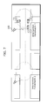
- FIG. 1 is a block diagram showing a configuration of a travel support system according to a first embodiment of the present invention
- FIG. 2 shows an image of an intersection recognized by a roadside apparatus
- FIG. 3 shows an exemplary image of Intersection Hanamachi 1 recognized by an image recognition unit
- FIG. 4 shows an example in which the position of each moving object is calculated from pixels recognized with the bottom left corner of the figure as the origin point, the horizontal axis as the X coordinate, and the vertical axis as the Y coordinate;
- FIGS. 5( a ) to ( c ) shows movement information of each vehicle detected by the roadside apparatus
- FIGS. 6( a ) to ( c ) shows the identification of the information-holding vehicle by using a matching degree of destinations
- FIG. 7 shows the provision of the non-equipped vehicle information
- FIG. 8 illustrates a notification of non-equipped vehicle information
- FIG. 9 shows an exemplary screen of a car navigation system included in a vehicle 4 ;
- FIGS. 10( a ) and ( b ) shows the non-equipped vehicle information provided from the information-holding vehicle, and then received by a non-equipped-vehicle information receiving unit;
- FIG. 11 shows an exemplary notification of non-equipped vehicle information
- FIG. 12 is a flow chart showing an exemplary operation of the entire travel support system according to the first embodiment
- FIG. 13 is a flow chart showing an exemplary non-equipped vehicle determination operation to be made by the non-equipped-vehicle determining unit 102 in Step 103 of FIG. 12 ;
- FIG. 14 is a flow chart showing an exemplary operation of the destination matching degree determining unit 103 in Step 105 of FIG. 12 ;
- FIG. 15 is a flow chart showing an exemplary operation of the equipped vehicle to be performed when the equipped vehicle receives the information regarding the non-equipped vehicle whose destination matches the destination of the equipped vehicle, from a non-equipped-vehicle information providing unit;
- FIG. 16 shows an exemplary minimum configuration of the travel support system according to the first embodiment
- FIG. 17 shows an exemplary positional relation between the equipped vehicle which receives the non-equipped vehicle information and the non-equipped vehicle, at an intersection, in terms of driving lanes;
- FIG. 18 shows an example in which the information-holding vehicle for holding the non-equipped vehicle information is identified by using turn signal information
- FIG. 19 is a block diagram showing the configuration of a travel support system according to the second embodiment, in which a matching degree of destinations is determined by using movement histories to identify an information-holding vehicle;
- FIG. 20 illustrates the movement histories stored in a vehicle movement history storing unit
- FIG. 21 shows an example in which detected position information is converted into a node sequence
- FIGS. 22( a ) to ( c ) shows exemplary movement histories stored in the vehicle movement history storing unit as a node sequence
- FIG. 23 shows an exemplary image of Intersection Hanamachi 1 recognized by the image recognition unit
- FIG. 24( a ) to ( c ) shows exemplary position information of the detected equipped and non-equipped vehicles
- FIG. 25 shows the destination of each vehicle predicted by a destination predicting unit
- FIG. 26 is a flow chart showing an exemplary operation of the entire travel support system according to the second embodiment.
- FIG. 27 is a flow chart showing an exemplary non-equipped vehicle determination operation to be made by the non-equipped-vehicle determining unit 102 in Step 103 of FIG. 26 ;
- FIG. 28 is a flow chart showing an exemplary operation of a destination matching degree determining unit in Step 105 of FIG. 26 ;
- FIG. 29 is a flow chart showing an exemplary operation of the equipped vehicle to be performed when the equipped vehicle receives the information regarding the non-equipped vehicle whose destination matches the destination of the equipped vehicle, from the non-equipped-vehicle information providing unit;
- FIG. 30 shows an exemplary image of Intersection Hanamachi 1 , recognized by the image recognition unit
- FIG. 31 shows an exemplary event at which the information-holding vehicle traveling to the destination different from the destination of the non-equipped vehicle shown by the non-equipped vehicle information, deletes unnecessary non-equipped vehicle information
- FIG. 32 is a block diagram showing the configuration of a travel support system according to a modified example 2 of the second embodiment
- FIG. 33 shows an example in which the information-holding vehicle provides the non-equipped vehicle information to another equipped vehicle to notify the presence of the non-equipped vehicle;
- FIG. 34 shows an example in which the non-equipped vehicle information received from the information-holding vehicle is displayed by an equipped vehicle
- FIG. 35 is a block diagram showing an exemplary hardware structure of a car navigation device included in a moving object capable of performing vehicle-to-vehicle communication according to the present invention.
- FIG. 36 is a block diagram showing the configuration of a moving object capable of performing the same process as the roadside apparatus according to the present invention.
- FIG. 1 is a block diagram showing a system configuration according to the first embodiment. Hereinafter, a description is given first for each constituent element, and then for operational flows according to the present invention.
- a roadside apparatus 100 placed on an intersection or a road includes: an image recognition unit 101 ; a non-equipped-vehicle determining unit 102 ; a destination matching degree determining unit 103 ; an information-holding vehicle identifying unit 104 ; a non-equipped-vehicle information providing unit 105 ; and a vehicle movement information detecting unit 106 .
- a roadside apparatus is provided at a predetermined intersection or roadside, as an intersection or traffic surveillance system (N system) and the like.
- N system intersection or traffic surveillance system
- Such a roadside apparatus has a function of transmitting and receiving information in communication networks or in the form of an image.
- a set of the image recognition unit 101 , the non-equipped-vehicle determining unit 102 , and the vehicle movement information detecting unit 106 shows one of the examples of an equipped-vehicle detecting unit which detects the presence and the position of a vehicle equipped with a communication module for communicating with another vehicle, and a non-equipped-vehicle detecting unit which detects the presence and the position of a vehicle that is not equipped with a communication module for communicating with another vehicle.
- the equipped-vehicle detecting unit further detects the moving direction of the equipped vehicle.
- the non-equipped-vehicle detecting unit includes: the image recognition unit 101 which obtains moving images and extracts vehicle images from the obtained moving images by recognizing moving objects in the moving images; the vehicle movement information detecting unit 106 which detects the movement information of a vehicle by communicating with the communication module included in the vehicle and obtaining position information of the vehicle from the vehicle including the communication module; and the non-equipped-vehicle determining unit 102 which determines, as the non-equipped vehicle, a vehicle with which the vehicle movement information detecting unit cannot communicate, from among the vehicles of the vehicle images extracted by the image recognition unit.
- the image recognition unit 101 identifies the position of the vehicle from the coordinates of the extracted vehicles in the moving image.
- the non-equipped-vehicle determining unit 102 further excludes one of the vehicles included in the position information detected by the vehicle movement information detecting unit 106 from among the vehicles extracted by the image recognition unit 101 , by checking the position of each vehicle identified by the image recognition unit 101 with the position information obtained by the vehicle movement information detecting unit 106 .
- the non-equipped-vehicle determining unit 102 determines a remaining one or more of the vehicles after the exclusion as the non-equipped vehicle.
- the roadside apparatus placed on an intersection or a road includes the image recognition unit 101 , the non-equipped-vehicle determining unit 102 , and the vehicle movement information detecting unit 106 , as examples of the equipped-vehicle detecting unit and the non-equipped-vehicle detecting unit; the information-holding vehicle identifying unit 104 as an example of the information-holding vehicle identifying unit; and the non-equipped-vehicle information providing unit 105 as an example of the non-equipped-vehicle information providing unit.
- the image recognition unit 101 included in the roadside apparatus 100 recognizes an image of an intersection or a route, using a camera or the like.
- FIG. 2 shows an image of an intersection recognized by the roadside apparatus.
- the roadside apparatus 100 is placed at Intersection Hanamachi 1 .
- the roadside apparatus 100 includes an intersection camera as the image recognition unit 101 .
- the roadside apparatus 100 recognizes a predetermined range as an image, for example, a range of the intersection shown by a dotted circle.
- FIG. 3 shows an exemplary image of Intersection Hanamachi 1 recognized by the image recognition unit 101 .
- the image recognition unit 101 extracts vehicle images from the moving images.
- the image recognition unit 101 can extract the moving images by obtaining a difference between the different image positions recognized in a predetermined sampling period. For example, in FIG. 3 , a vehicle 1 is recognized at a position of 1 A at a given point in time, and the vehicle 1 is then recognized at a position of 1 B at the next point in time.
- the vehicle 1 can be extracted as a moving image.
- a vehicle 2 and a vehicle 3 are extracted as moving images based on the difference between the different image positions recognized similarly.
- the position information of each extracted moving image is also calculated. Since the roadside apparatus has a predetermined reference point such as the position where the roadside apparatus is placed, the position information of each recognized moving object can be calculated based on the reference point.
- FIG. 4 shows an example in which the position of each moving object is calculated from pixels recognized with the bottom left corner of the figure as the origin point, the horizontal axis as the X coordinate, and the vertical axis as the Y coordinate.
- the image to be recognized has coordinates of (E135.30.00, N35.10.00); (E135.30.00, N35.12.00); (E135.31.00, N35.12.00); and (E135.31.00, N35.10.00), at the four corners of the image.
- the position of each moving object can be calculated. For example, as shown in FIG. 4 , the position of each moving object is calculated from the recognized pixels with the bottom left corner of the figure as the origin point, the horizontal axis as the X coordinate, and the vertical axis as the Y coordinate. In this example, based on the bottom left coordinates (0, 0) corresponding to the coordinates (E135.30.00, N35.10.00), the coordinates of the vehicle 1 is calculated as (10, 10) and the position of the vehicle 1 as (E135.30.10, N35.11.10). Similarly, the position of each vehicle is calculated.
- the position of the vehicle 2 is at the coordinates (E135.30.13, N35.11.15), and the position of the vehicle 3 is at the coordinates (E135.30.15, N35.11.10). Furthermore, based on a sampling period to be detected and a difference between different image positions, the speed and the moving direction of each moving object can be calculated.
- the vehicle 1 has coordinates of (E135.30.11, N35.11.10) at the position of 1 A, and then has the coordinates of (E135.30.10, N35.11.10) at the position of 1 B after 0.5 second. Since the distance between 1 A and 1 B is equal to one second east longitude, the roadside apparatus calculates that the vehicle 1 travels approximately at a speed of 50 km an hour in the west direction.
- this calculation is performed by roughly converting one second east longitude to 25 m.
- the roadside apparatus calculates that the vehicle 2 travels at a speed of 40 km an hour in the north direction, and the vehicle 3 at a speed of 50 km an hour in the west direction.
- the vehicle movement information detecting unit 106 detects the position information of each vehicle.
- vehicles include a unit which detects their own current position by a GPS such as a car navigation system. Furthermore, in vehicle-to-vehicle communication, the vehicles transmit the detected position information therebetween, so as to avoid occurrence of a head-on collision, and to merge with other traffic safely.
- each vehicle transmits its movement information and the like to a roadside apparatus placed on an intersection or along a route so that the server of the roadside apparatus can use the movement information as information regarding traffic congestion. Also in the first embodiment, the roadside apparatus detects the movement information of each vehicle.
- FIGS. 5( a )-( c ) show the movement information of each vehicle detected by the roadside apparatus 100 .
- FIG. 5( a ) shows an example of the position information of equipped vehicles detected by the roadside apparatus in communication networks.
- the movement information detected from the vehicle 1 includes “ 001 ” as a vehicle ID; (E135.30.10, N35.11.10) as position information; “west” as a moving direction; and “50 km/h” as a speed.
- the movement information detected from the vehicle 2 includes “ 002 ” as a vehicle ID; (E135.30.13, N35.11.10) as position information; “north” as a moving direction; and “40 km/h” as a speed.
- FIG. 5( b ) shows exemplary position information of each vehicle detected by the roadside apparatus 100 by image recognition.
- vehicle-to-vehicle communication and communication with the roadside apparatus are established through a module, it is impossible to communicate with a vehicle having no communication module (non-equipped vehicle). Therefore, for example, even when a given vehicle has a system for making a notification to avoid occurrence of a head-on collision with another vehicle recognized in vehicle-to-vehicle communication, the system-equipped vehicle cannot recognize a vehicle in the case where the vehicle is a non-equipped vehicle. This increases the collision risk with a non-equipped vehicle. Accordingly, it is an object of the first embodiment to avoid such a collision risk by identifying a non-equipped vehicle so that an equipped vehicle holds the non-equipped vehicle information.
- the non-equipped-vehicle determining unit 102 determines whether or not a given vehicle is a non-equipped vehicle having no communication module, from images recognized by the image recognition unit 101 , and from the position information of each vehicle detected by the vehicle movement information detecting unit 106 .
- FIGS. 5( a )-( c ) illustrate the determination to be made whether or not a given vehicle is a non-equipped vehicle.
- the vehicle movement information detecting unit 106 has detected the movement information of each vehicle.
- the image recognition unit 101 has recognized each moving object, the position, the moving speed, and the moving direction of the moving object.
- the non-equipped-vehicle determining unit 102 determines that a given vehicle is a non-equipped vehicle. For example, the position (E135.30.10, N35.11.10), the moving direction “west”, and the speed “50 km/h” included in the movement information of the vehicle 1 detected by the vehicle movement information detecting unit 106 (see FIG.
- the vehicle having the recognition ID “ 101 ” can be identified as the vehicle 1 .
- the position (E135.30.13, N35.11.10), the moving direction “north”, and the speed “40 km/h” included in the movement information of the vehicle 2 see FIG.
- FIG. 5( a ) shows exemplary position information of the vehicle identified as a non-equipped vehicle.
- the information of the vehicle recognized as the vehicle having the recognition ID “ 103 ” shown in FIG. 5( b ) is not detected by the vehicle movement information detecting unit 106 . Therefore, the vehicle is identified as a non-equipped vehicle equipped with no communication module (see FIG.
- each vehicle is identified when matching is found in terms of position and speed.
- a positional or speed error may appear in image recognition, and the position detected by a GPS or the like may also have an error. Therefore, each vehicle can be identified by applying a predetermined threshold level to the vehicle, not limited to matching.
- a conventional technique of associating the moving object obtained by image-recognition with the position information detected by another means is known, and the description thereof is omitted here.
- the information-holding vehicle identifying unit 104 is an exemplary information-holding vehicle identifying unit which identifies an information-holding vehicle from the equipped vehicles detected by the equipped-vehicle detecting unit, based on the positions of the equipped vehicles detected by the equipped-vehicle detecting unit and the position of the non-equipped vehicle detected by the non-equipped-vehicle detecting unit.
- the information-holding vehicle is an equipped vehicle for holding the non-equipped vehicle information including the information regarding the position of the non-equipped vehicle.
- the information-holding vehicle identifying unit 104 identifies the vehicle for holding the information regarding the non-equipped vehicle determined by the non-equipped-vehicle determining unit 102 (hereinafter, referred to as an “information-holding vehicle).
- the destination matching degree determining unit 103 is an exemplary destination matching degree determining unit which determines the matching degree of destinations between each equipped vehicle and a non-equipped vehicle, based on the position of the equipped vehicle detected by the equipped-vehicle detecting unit and the position of the non-equipped vehicle detected by the non-equipped-vehicle detecting unit.
- the information-holding vehicle identifying unit identifies the equipped vehicle which is determined by the destination matching degree determining unit to have a high matching degree of destinations with the non-equipped vehicle, as the information-holding vehicle.
- the destination matching degree determining unit determines that the equipped vehicle and the non-equipped vehicle match each other at a high degree in terms of destination in the case where the moving direction of the equipped vehicle detected by the equipped-vehicle detecting unit matches with the moving direction of the non-equipped vehicle detected by the non-equipped-vehicle detecting unit. Furthermore, the destination matching degree determining unit determines the matching degree between the destinations of the equipped vehicle and the non-equipped vehicle predicted by the destination predicting unit. In the first embodiment, for example, the destination matching degree determining unit 103 determines a matching degree of movement between the non-equipped vehicle and each equipped vehicle, based on the movement information recognized by the image recognition unit 101 . The destination matching degree determining unit 103 then identifies the vehicle for holding the non-equipped vehicle information, based on the determined matching degree of destinations.
- FIGS. 6( a )-( c ) show the identification of the information-holding vehicle by using the matching degree of destinations.
- FIG. 6( a ) shows exemplary position information of equipped vehicles. In this case, as described above, the positions, the moving directions, and the speeds of the vehicle 1 and the vehicle 2 have been identified.
- FIG. 6( b ) shows exemplary position information of the vehicle identified as a non-equipped vehicle. At the same time, the position, the moving direction, and the speed of the vehicle identified as a non-equipped vehicle (hereinafter, referred to as a vehicle 3 ) have also been recognized.
- the destination matching degree determining unit 103 determines the matching degree of destinations between the non-equipped vehicle and each vehicle. Referring to FIGS.
- the moving direction “west” and the speed “50 km/h” of the non-equipped vehicle are different from the moving direction “north” and the speed “40 km/h” of the vehicle 2 .
- the vehicle 2 tries to hold the information of the vehicle 3 as a non-equipped vehicle in this case, the vehicles are parted from each other due to their different moving directions. Therefore, the vehicle 2 is not suitable as the information-holding vehicle.
- the vehicle 1 has a matching moving direction of “west” and a matching speed “50 km/h” with those of the vehicle 3 .
- the movements of the vehicles are similar to each other. Therefore, in this example, the vehicle 1 is identified as the information-holding vehicle.
- the non-equipped-vehicle information providing unit 105 is an exemplary non-equipped-vehicle information providing unit which provides the non-equipped vehicle information to the information-holding vehicle identified by the information-holding vehicle identifying unit.
- the non-equipped-vehicle information providing unit 105 provides the non-equipped vehicle information to the vehicle identified as an equipped vehicle.
- FIG. 7 shows the provision of the non-equipped vehicle information.
- the non-equipped vehicle information regarding the vehicle 3 is provided to the vehicle 1 identified as the information-holding vehicle by the roadside apparatus 100 .
- the non-equipped vehicle information includes, for example, the position of the non-equipped vehicle relative to the information-holding vehicle, and the moving speed thereof.
- 6( c ) shows exemplary non-equipped vehicle information as the information regarding the non-equipped vehicle.
- the non-equipped-vehicle information providing unit 105 thus provides the information regarding the vehicle 3 identified as the non-equipped vehicle, to the vehicle 1 as the information-holding vehicle.
- an equipped vehicle (moving object) 200 has been identified as the information-holding vehicle.
- the equipped vehicle 200 includes: a non-equipped-vehicle information receiving unit 201 ; a vehicle movement information detecting unit 203 ; and a non-equipped-vehicle information notifying unit 202 .
- the equipped vehicle 200 makes a notification about the non-equipped vehicle information.
- the non-equipped-vehicle information receiving unit 201 is an exemplary communication unit included in the information-holding vehicle.
- the non-equipped-vehicle information receiving unit 201 holds the non-equipped vehicle information provided by the non-equipped-vehicle information providing unit, as well as provides the holding non-equipped vehicle information to another equipped vehicle through the communication module thereof.
- the non-equipped-vehicle information receiving unit 201 receives the non-equipped vehicle information.
- the vehicle movement information detecting unit 203 as the aforementioned vehicle movement information detecting unit 106 , is a vehicle-to-vehicle module employed for communicating about the position information detected by the GPS or the like included in each vehicle, so as to avoid occurrence of a head-on collision.
- the non-equipped-vehicle information notifying unit 202 makes a notification about the received non-equipped vehicle information, based on the position of the other vehicle detected by the vehicle movement information detecting unit 203 .
- a description is given with reference to the drawings.
- FIG. 8 illustrates a notification of non-equipped vehicle information.
- the vehicle 1 is traveling through Intersection Hanamachi 1 to the west.
- a vehicle 4 is traveling through Intersection Urabana 2 to the north.
- Intersection Urabana 2 is so blind that the vehicles cannot know that the vehicles are approaching each other.
- the vehicle movement information detecting unit 203 as a communication module which allows this vehicle-to-vehicle communication, communicates about each other's position information, so as to avoid occurrence of a head-on collision.
- FIG. 9 shows an exemplary screen of the car navigation system included in the vehicle 4 .
- the vehicle 4 which is positioned close to Intersection Urabana 2 , is notified that a vehicle is approaching, based on the movement information of the vehicle 1 detected by the vehicle movement information detecting unit 203 .
- This allows the user of the vehicle 4 to know that the vehicle 1 is approaching.
- the user cannot recognize the vehicle 3 , which is a non-equipped vehicle positioned in the rear of the vehicle'.
- the non-equipped-vehicle information notifying unit 202 notifies the non-equipped vehicle information to avoid such a collision.
- FIGS. 10( a ) and ( b ) show the non-equipped vehicle information which is provided from the vehicle 1 that is the information-holding vehicle and is received by the non-equipped-vehicle information receiving unit 201 .
- the equipped vehicle 4 receives non-equipped vehicle information as shown in FIG. 10( b ).
- the non-equipped vehicle information includes the recognition ID “ 103 ”, the relative position “125 meters backward”, and the speed “50 km/h”.
- the non-equipped-vehicle information notifying unit 202 notifies the non-equipped vehicle information thus obtained.
- FIG. 11 shows an exemplary notification of non-equipped vehicle information.
- FIG. 11 is different from FIG. 9 in that the notification is made that non-equipped vehicles are approaching 250 meters backward, in addition to the information that the vehicle 1 is approaching.
- the user can know not only that a vehicle is approaching, but also that a non-equipped vehicle is present around the equipped vehicle. This allows safety traveling of a vehicle.
- a non-equipped vehicle can be detected with a high degree of precision. Furthermore, a collision can be avoided over a wide range, regardless of the presence or absence of any camera-mounted vehicle.
- FIG. 12 is a flow chart showing an exemplary operation of the entire travel support system according to the first embodiment.
- FIG. 13 is a flow chart showing an exemplary non-equipped vehicle determination operation to be made by the non-equipped-vehicle determining unit 102 in Step 103 of FIG. 12 .
- FIG. 14 is a flow chart showing an exemplary operation of the destination matching degree determining unit 103 in Step 105 of FIG. 12 .
- 15 is a flow chart showing an exemplary operation of the equipped vehicle 200 to be performed when the equipped vehicle 200 receives the information regarding the non-equipped vehicle whose destination matches the destination of the equipped vehicle 200 , from the non-equipped-vehicle information providing unit 105 .
- the image recognition unit 101 recognizes images (Step S 101 ).
- the vehicle movement information detecting unit 106 communicates with the communication module included in each equipped vehicle, to detect the position information of the vehicle, from the vehicle including the communication module (Step S 102 ).
- the non-equipped-vehicle determining unit 102 determines a non-equipped vehicle (Step S 103 ).
- Step S 201 vehicle images are extracted from the image information.
- the position information of the extracted vehicle images is calculated (Step S 202 ).
- Step S 203 the position information detected by the vehicle movement information detecting unit 106 is referred to (Step S 203 ).
- a determination is made whether or not any moving object of which position has not been detected is present, specifically, whether or not any non-equipped vehicle is present (Step S 204 ). When no such moving object is present (Step S 204 : No), this means that no non-equipped vehicle is present.
- the operation returns to the main flow.
- Step S 204 Yes
- the moving object is determined as a non-equipped vehicle (Step S 205 ). The operation then returns to the main flow.
- Step S 104 When any non-equipped vehicle is present (Step S 104 : Yes), the operation moves on to Step S 105 .
- Step S 104 When no non-equipped vehicle is present (Step S 104 : No), the operation returns to Step S 101 to repeat the steps of vehicle detection to non-equipped vehicle determination (Step S 101 to Step S 104 ).
- Step S 104 the destination matching degree determining unit 103 determines the matching degree of destinations between the non-equipped vehicle and the equipped vehicle.
- Step S 301 the movement information of one of the vehicles recognized in the image information is referred to.
- the moving directions of the non-equipped vehicle and the equipped vehicle are compared to determine whether or not the moving directions match each other (Step S 302 ).
- Step S 302 Yes
- the operation moves on to Step S 303 .
- Step S 306 the operation moves on to Step S 306 .
- Step S 303 a determination is made whether or not the moving speed of the equipped vehicle is within a predetermined range.
- Step S 303 When the moving speed is within the predetermined range (Step S 303 : Yes), the operation moves on to Step S 304 . When the moving speed is beyond the range, the operation moves on to Step S 306 .
- Step S 304 a determination is made whether or not the position of the equipped vehicle is within a predetermined range (Step S 304 ).
- Step S 304 When the position is within the predetermined range (Step S 304 : Yes), the operation moves on to Step S 305 .
- Step S 306 When beyond the range, the operation moves on to Step S 306 .
- the equipped vehicle is identified as a candidate for the information-holding vehicle (Step S 305 ).
- Step S 306 a determination is made whether or not any other vehicle which has not been determined yet is left.
- Step S 306 Yes
- the operation returns to Step S 301 to determine the undetermined vehicle.
- Step S 306 No
- one of the equipped vehicles, of which position is the closest to the position of the non-equipped vehicle among the candidates for the information-holding vehicle is identified as the information-holding vehicle (Step S 307 ). The operation then returns to the main flow.
- the information-holding vehicle identifying unit 104 identifies the vehicle identified in the above flow, as an information-holding vehicle (Step S 106 ).
- the non-equipped vehicle information is provided to the information-holding vehicle (Step S 107 ).
- the non-equipped-vehicle information receiving unit 201 in the equipped vehicle 200 which has been identified as the information-holding vehicle receives the non-equipped vehicle information as shown in FIG. 1 (Step S 401 ).
- the vehicle movement information detecting unit 203 detects position information of another equipped vehicle in vehicle-to-vehicle communication (Step S 402 ).
- the non-equipped-vehicle information notifying unit 202 notifies the non-equipped vehicle information to the user (Step S 403 ).
- FIG. 16 shows an exemplary minimum configuration of the travel support system according to the first embodiment.
- a non-equipped vehicle is detected based on the images recognized by the image recognition unit 101 and the vehicle position information detected by the vehicle movement information detecting unit 106 .
- the first embodiment is not limited to such a case.
- a non-equipped vehicle can be detected by detecting moving objects using a sensor such as a millimeter-wave sensor as a speed detector. Therefore, the system according to the first embodiment can be achieved by the system constituent elements shown in FIG. 16 .
- a non-equipped-vehicle detecting unit 111 is an exemplary non-equipped-vehicle detecting unit which detects the presence and the position of a non-equipped vehicle equipped with no communication module for communicating with another vehicle.
- the non-equipped-vehicle detecting unit 111 detects a non-equipped vehicle equipped with no communication module for communication.
- the non-equipped-vehicle detecting unit further detects the moving direction of the non-equipped vehicle.
- An equipped-vehicle detecting unit 112 is an exemplary equipped-vehicle detecting unit which detects the presence and the position of an equipped vehicle equipped with a communication module for communicating with another vehicle.
- the equipped-vehicle detecting unit 112 detects an equipped vehicle equipped with the communication module for the communication.
- An information-holding vehicle identifying unit 113 identifies a vehicle for holding the information of the non-equipped vehicle, from among equipped vehicles, based on the position of the non-equipped vehicle and the position of the equipped vehicle.
- a non-equipped-vehicle information providing unit 105 provides the information of the non-equipped vehicle to the vehicle identified by the information-holding vehicle identifying unit 113 .
- a communicating unit 115 provides the information of the non-equipped vehicle, held by the information-holding vehicle, to another equipped vehicle equipped with the communication module, in communication networks.
- the image recognition unit 101 shown in FIG. 1 corresponds to the non-equipped-vehicle detecting unit 111 included in the roadside apparatus.
- the vehicle movement information detecting unit 106 corresponds to the equipped-vehicle detecting unit 112 .
- a set of the destination matching degree determining unit 103 and the information-holding vehicle identifying unit 104 corresponds to the information-holding vehicle identifying unit 113 .
- a set of the non-equipped-vehicle information receiving unit 201 , the vehicle movement information detecting unit 203 , and the non-equipped-vehicle information notifying unit 202 , included in each equipped vehicle, corresponds to a communicating unit 205 .
- the communicating unit 205 holds the non-equipped vehicle information provided by the non-equipped-vehicle information providing unit.
- the communicating unit 205 also provides the holding non-equipped vehicle information to another equipped vehicle through the communication module.
- the vehicle whose moving direction is the same as that of the non-equipped vehicle is identified as the information-holding vehicle for receiving the non-equipped vehicle information. This is because the vehicle whose moving direction is the same as that of the non-equipped vehicle is likely to follow the non-equipped vehicle.
- the vehicle having the same moving direction is identified as the information-holding vehicle so that the non-equipped vehicle information is provided to the information-holding vehicle different from the non-equipped vehicle. This can avoid a collision and the like.
- the information-holding vehicle whose moving direction is the same moving direction but also the information-holding vehicle traveling in the same driving lane as the non-equipped vehicle, can be identified as the information-holding vehicle.
- the equipped-vehicle detecting unit 112 as an exemplary equipped-vehicle detecting unit, further detects the driving lane of the road on which each equipped vehicle is traveling.
- the non-equipped-vehicle detecting unit 111 as an exemplary non-equipped-vehicle detecting unit, further detects the driving lane of the road on which the non-equipped vehicle is traveling.
- the destination matching degree determining unit 103 determines that the equipped vehicle and the non-equipped vehicle match each other at a high degree in terms of destination.
- FIG. 17 shows an exemplary positional relation between the equipped vehicle which receives the non-equipped vehicle information and the non-equipped vehicle, at an intersection, in terms of driving lanes.
- FIG. 17 shows the intersection “Intersection Hanamachi 5 ”. Intersection Hanamachi 5 has two driving lanes each way.
- the lane closer to the roadside is for straight-ahead vehicles.
- the center driving lane is for right-turning vehicles.
- the non-equipped-vehicle detecting unit 111 has detected the vehicle 3 as a non-equipped vehicle.
- the equipped-vehicle detecting unit 112 has detected the vehicle 1 and the vehicle 2 as equipped vehicles.
- the driving lane information is employed so that the information-holding vehicle identifying unit 113 identifies an information-holding vehicle for holding the non-equipped vehicle information, from among the equipped vehicles.
- the vehicle 3 that is the non-equipped vehicle is traveling on the straight-ahead driving lane.
- the vehicle 1 is similarly traveling on the straight-ahead driving lane.
- the vehicle 2 is traveling on the right-turning driving lane.
- the information-holding vehicle identifying unit 113 identifies the vehicle 1 as the information-holding vehicle. This is because the vehicles traveling the same lane are likely to travel in the same direction.
- the information-holding vehicle can be identified based on the driving lanes, in such a manner.
- the information-holding vehicle can be identified by detecting a turn signal given by a direction indicator.
- the non-equipped-vehicle detecting unit 111 as the exemplary equipped-vehicle detecting unit further detects a turn signal given by a direction indicator included in each equipped vehicle.
- the non-equipped-vehicle detecting unit 111 as the non-equipped-vehicle detecting unit further detects a turn signal given by a direction indicator included in the non-equipped vehicle.
- the destination matching degree determining unit 103 as the exemplary destination matching degree determining unit determines that the matching degree between the destination of the equipped vehicle and the destination of the non-equipped vehicle is high.
- FIG. 18 shows an example in which the information-holding vehicle for holding the non-equipped vehicle information is identified by using the turn signal information.
- FIG. 18 shows the intersection “Intersection Hanamachi 1 ”.
- the non-equipped-vehicle detecting unit 111 has detected the vehicle 3 as a non-equipped vehicle.
- the equipped-vehicle detecting unit 112 has detected the vehicle 1 and the vehicle 2 as equipped vehicles.
- the information-holding vehicle identifying unit 113 employs the turn signal information to identify an information-holding vehicle for holding the non-equipped vehicle information, from among the equipped vehicles.
- FIG. 18 shows the intersection “Intersection Hanamachi 1 ”.
- the non-equipped-vehicle detecting unit 111 has detected the vehicle 3 as a non-equipped vehicle.
- the equipped-vehicle detecting unit 112 has detected the vehicle 1 and the vehicle 2 as equipped vehicles.
- the information-holding vehicle identifying unit 113 employs the turn signal information to identify an information-holding vehicle for holding the non-equipped vehicle information, from among the equipped
- the vehicle 1 flashes neither its right-turning signal nor left-turning turn signal because the vehicle 1 is traveling straight ahead.
- the vehicle 2 flashes its right-turning signal for turning to the right.
- the vehicle 3 as the non-equipped vehicle as the vehicle 1 , flashes neither its right-turning signals nor left-turning turn signals. In other words, the vehicle 3 is likely to travel straight ahead.
- the information-holding vehicle identifying unit 113 identifies the vehicle 1 as the information-holding vehicle. By employing the turn signal information, the moving directions of each vehicle can be identified. By employing the turn signal information, the information-holding vehicle can also be identified.
- the non-equipped-vehicle detecting unit 111 and the equipped-vehicle detecting unit 112 can detect change in brightness caused by light or flash relatively easily in image recognition by employing a camera or the like. Since each vehicle generally employs turn signals to indicate where the vehicle goes next, the non-equipped vehicle information can be provided more accurately by employing the turn signal information to identify the information-holding vehicle. Furthermore, since turn signals flash at nighttime, in contrast to head lamp indicators on at all times, the moving direction of each vehicle can be identified by detecting their flashing lights. This allows the information-holding vehicle to be identified.
- the roadside apparatus placed on an intersection or the like can recognize equipped and non-equipped vehicles over a wide range. Furthermore, the roadside apparatus can recognize the moving directions of the equipped and non-equipped vehicles by following their driving lanes and turn signals. Based on this recognition result, the travel support system can identify the most suitable one for the information-holding vehicle, from among the equipped vehicles, so that the non-equipped vehicle information is provided thereto.
- the information includes not only the non-equipped vehicle information according to the first embodiment, but also information exchanged with a pedestrian such as a child on a crosswalk. Therefore, excessive information exchange is favorably avoided.
- the presence of the non-equipped vehicle is notified not to all the surrounding vehicles, but to the specific vehicle as shown in the first embodiment, so that excessive information exchange is avoided, thereby preventing a collision appropriately.
- the vehicle whose destination matches with the destination of the non-equipped vehicle is identified as the information-holding vehicle.
- the non-equipped vehicle information is provided to the information-holding vehicle.
- a description is given for a method of predicting the destination of each vehicle by using the movement history thereof so as to identify the information-holding vehicle, and then providing the non-equipped vehicle information to the information-holding vehicle.
- FIG. 19 shows a system configuration according to the second embodiment.
- a vehicle movement history storing unit 107 and a destination predicting unit 108 are further included.
- the constituent elements shown in the first embodiment have the same numbers also in the second embodiment, and their description is omitted here.
- the vehicle movement history storing unit 107 is an exemplary movement history storing unit which stores the movement histories of equipped and non-equipped vehicles, based on the position of each equipped vehicle detected by the equipped-vehicle detecting unit, and based on the position of the non-equipped vehicle detected by the non-equipped-vehicle detecting unit.
- the vehicle movement history storing unit 107 stores the position information of each vehicle detected by the vehicle movement information detecting unit 106 as the movement history of the vehicle.
- the position information detected from each vehicle indicates which route the vehicle has passed through, how much time has been required for passing through the route, and the like.
- the movement history through a predetermined route is provided to a roadside apparatus or the like so that the time required for passing through the route is calculated accurately.
- This can provide more accurate traffic information or the like to another vehicle.
- the user can search a past transit across the user's own movement history, can make a route setting to be affected by the past transit route, for example.
- the movement history stored for each user is affected by the user's behavior pattern.
- the user's future destination can be predicted.
- their general future destinations and the like can be predicted, when the users pass through a specific route.
- the destination predicting unit 108 is an exemplary destination predicting unit which predicts the destinations of equipped and non-equipped vehicles, based on the movement histories of the equipped and non-equipped vehicles stored in the movement history storing unit.
- the destination predicting unit 108 predicts the destination of each vehicle based on the movement histories stored in the vehicle movement history storing unit 107 .
- FIG. 20 illustrates the movement histories stored in the vehicle movement history storing unit 107 .
- the GPS or the like included in each vehicle generally detects latitude-longitude information at a predetermined interval (for example, one second), based on the user movement.
- a predetermined interval for example, one second
- position information is detected.
- the detected position information is shows by white circles.
- the position information is stored by converting into a node sequence in which intersections or the like are employed as nodes.
- FIG. 21 shows an example in which detected position information is converted into a node sequence.
- a user has turned to the right at Intersection Hanamachi 1 to travel straight ahead, and then just has passed through Intersection Hanamachi 2 . The movement of the user is followed so that position information is detected.
- map information which is included in a car navigation system or the like, employs intersections and facilities as nodes.
- the map information generally includes road network information constructed by linkages which connects one node with another. Each node or linkage in the road network information has a unique ID. For example, the ID of Intersection Hanamachi 1 is “N (node) 100 ”, and the ID of Intersection Hanamachi 2 is “N 101 ”.
- the detected position information is converted into nodes by matching.
- This node sequence is stored as movement histories.
- the history ID “ 001 ” is converted into “N 100 ⁇ N 101 ”, and then stored as a movement history.
- FIGS. 22( a )-( c ) show exemplary movement histories stored in the vehicle movement history storing unit 107 as a node sequence.
- the history ID “ 001 ” has a transit history that the vehicle corresponding to the history ID “ 001 ” starts from the starting point “N 201 ”, via the routes “N 202 ”, “N 203 ”, and the like, and then reaches the destination “N 220 ”.
- the destination predicting unit 108 predicts a future destination, based on the movement histories stored in the vehicle movement history storing unit 107 and the current transits detected by the vehicle movement information detecting unit 106 .
- the vehicle movement history storing unit 107 stores the movement histories as shown above.
- a given vehicle currently traveling, has started from “N 201 ” and passed through “N 202 ”, “N 203 ”, “N 204 ”, “N 205 ”, and “N 206 ”, as shown in FIG. 22( b ).
- the destination predicting unit 108 searches for a matching route across the movement histories stored in the vehicle movement history storing unit 107 to predict a subsequent destination.
- the transit up to the current time shown in FIG. 22( b ) matches with the transit having the history ID “ 001 ”.
- a prediction can be made that the vehicle corresponding to the history ID “ 001 ” will pass through “N 207 ”, “N 208 ”, “N 209 ”, and “N 210 ”, and finally reach the destination “N 220 ”.
- the information-holding vehicle identifying unit 104 identifies the information-holding vehicle for holding the non-equipped vehicle information.
- the destination matching degree determining unit 103 determines a matching degree of destinations to identify the information-holding vehicle.
- a matching degree of destinations is determined to identify the information-holding vehicle.
- FIG. 23 shows an exemplary image of Intersection Hanamachi 1 recognized by the image recognition unit 101 .
- FIG. 23 shows an image of Intersection Hanamachi 1 .
- a vehicle 1 , a vehicle 2 , and a vehicle 3 are extracted as moving images.
- the positions of the moving objects are: (E135.30.10, N35.11.10); (E135.30.13, N35.11.10); and (E135.30.15, N35.11.10).
- the fact that the moving objects are traveling from the east to the west along Intersection Hanamachi 1 is obtained by calculation, as the moving directions of the moving objects.
- the vehicle movement information detecting unit 106 detects the position information transmitted from each vehicle.
- FIG. 24( a )-( c ) show an exemplary the position information of the detected equipped and non-equipped vehicles.
- FIG. 24( a ) shows exemplary position information transmitted from the vehicle 1 and the vehicle 2 that are equipped vehicles.
- FIG. 24( b ) shows exemplary position information of the vehicle 1 , and the vehicle 2 , and the vehicle 3 , detected by the image recognition unit 101 by image processing.
- FIG. 24( c ) shows exemplary position information of the detected non-equipped vehicle.
- the position information detected from the vehicle 1 includes: “ 001 ” as a vehicle ID; (E135.30.10, N35.11.10) as a position; “west” as a moving direction, and “50 km/h” as a speed.
- the position information detected from the vehicle 2 includes: “ 002 ” as a vehicle ID; (E135.30.13, N35.11.10) as a position; “west” as a moving direction; and “50 km/h” as a speed.
- the difference is obtained, between the position detected by the vehicle movement information detecting unit 106 and the position information shown in FIG. 24( b ) image-recognized by the image recognition unit 101 .
- a destination matching degree is employed so that the destination matching degree determining unit 103 identifies the information-holding vehicle.
- the moving direction of the vehicle 3 that is a non-equipped vehicle (hereinafter, referred to as a “non-equipped vehicle 3 ”) is west. Since the moving directions of the vehicle 1 and the vehicle 2 match each other, the vehicle 1 and the vehicle 2 become candidates for the information-holding vehicle. Furthermore, the vehicle 2 of which position is the closest to the position of the non-equipped vehicle 3 , is identified as the information-holding vehicle, for example.
- the movement of each vehicle cannot be accurately predicted only based on the movement thus recognized by the roadside apparatus. Therefore, the vehicle 2 is sometimes inappropriate as the information-holding vehicle. For example, in FIG.
- a destination matching degree is further determined by using the destinations predicted by the destination predicting unit 108 .
- FIG. 25 shows the destination of each vehicle predicted by the destination predicting unit 108 .
- the destinations of the vehicle 1 and the vehicle 2 are predicted based on the movement history of each vehicle, as described above. For example, a destination prediction is made that the vehicle 1 may pass through Intersection Hanamachi 1 , and then travel straight ahead through Intersection Urabana 2 toward Intersection Hanamachi 3 .
- another destination prediction is made based on movement history of the vehicle 2 , that the vehicle 2 may pass through Intersection Hanamachi 1 , and then turn to the right at Intersection Urabana 2 toward Intersection Urabana 4 .
- the vehicle 3 since the vehicle 3 is a non-equipped vehicle having no communication module, the vehicle 3 can neither store its movement history, nor predict its destination accurately based on the history. Therefore, the destination of the non-equipped vehicle 3 can only be estimated, not predicted. For example, an estimate is made that the vehicle 3 may travel ahead through Intersection Hanamachi 1 .
- a general destination can be predicted by employing frequency or the like, so that the predicted destination is employed as the destination of the non-equipped vehicle for estimate.
- the destination matching degree determining unit 103 calculates the destination matching degree between the predicted and estimated destinations.
- the information-holding vehicle identifying unit 104 identifies the information-holding vehicle.
- the non-equipped vehicle 3 may travel straight ahead up to Intersection Hanamachi 3 by estimate, while the vehicle 2 turns to the right at Intersection Hanamachi 2 .
- the transit of the non-equipped vehicle 3 matches the transit of the vehicle 1 up to Intersection Hanamachi 3 . Therefore, the vehicle 1 is identified as the information-holding vehicle.
- the vehicle 2 turning to the right at Intersection Hanamachi 2 , travels away from the non-equipped vehicle. This means that the vehicle 2 does not need to hold the information about the presence of the non-equipped vehicle any longer.
- FIG. 26 is a flow chart showing an exemplary operation of the entire travel support system according to the second embodiment.
- FIG. 27 is a flow chart showing an exemplary non-equipped vehicle determination operation to be made by the non-equipped-vehicle determining unit 102 in Step 103 of FIG. 26 .
- FIG. 28 is a flow chart showing an exemplary operation of the destination matching degree determining unit 103 in Step 105 of FIG. 26 .
- 29 is a flow chart showing an exemplary operation of the equipped vehicle 200 to be performed when the equipped vehicle 200 receives the information regarding the non-equipped vehicle whose destination matches the destination of the equipped vehicle 200 , from the non-equipped-vehicle information providing unit 105 .
- the image recognition unit 101 recognizes images (Step S 101 ).
- the vehicle movement information detecting unit 106 detects the position information of each vehicle (Step S 102 ).
- the non-equipped-vehicle determining unit 102 determines a non-equipped vehicle (Step S 103 ).
- Step S 201 vehicle images are extracted from the image information.
- the position information of the extracted vehicle images is calculated (Step S 202 ).
- Step S 203 the position information detected by the vehicle movement information detecting unit 106 is referred to (Step S 203 ).
- a determination is made whether or not any moving object of which position information has not been detected is present (Step S 204 ). When no such moving object is present (Step S 204 : No), this means that no non-equipped vehicle is present.
- the operation returns to the main flow.
- Step S 204 Yes
- the moving object is determined as a non-equipped vehicle (Step S 205 ). The operation then returns to the main flow.
- Step S 104 when any non-equipped vehicle is present (Step S 104 : Yes), the operation moves on to Step S 105 .
- Step S 104 When no non-equipped vehicle is present (Step S 104 : No), the operation returns to Step S 101 to repeat the steps of vehicle detection to non-equipped vehicle determination (Step S 101 to Step S 104 ).
- Step S 104 When any non-equipped vehicle is present (Step S 104 : Yes), the vehicle movement information detecting unit 106 detects the position information of the vehicle (Step S 501 ). The vehicle movement history storing unit 107 then stores the detected position information (Step S 502 ). Next, the movement history is referred to (Step S 503 ). The destination predicting unit 108 predicts the destination of the vehicle (Step S 504 ).
- the destination matching degree determining unit 103 determines the matching degree of destinations (Step S 505 ).
- each vehicle having a vehicle-to-vehicle communication module can predict the future destination of the vehicle, based on the detected position information and movement history thereof. For example, as shown in FIG. 25 , a prediction is made that the equipped vehicle 1 may travel straight ahead through Intersection Hanamachi 1 , toward Intersection Urabana 2 and Intersection Hanamachi 3 . Another prediction is made that the equipped vehicle 2 may turn to the right at Intersection Hanamachi 2 . On the other hand, an estimate is made that the non-equipped vehicle 3 may travel straight ahead up to Intersection Hanamachi 3 . These predicted and estimated destinations are referred to so that the matching degree of destinations is determined. The information-holding vehicle is thus identified.
- Step S 601 first the predicted and estimated destinations are referred to (Step S 601 ).
- a determination is made whether or not the moving direction of one equipped vehicle matches the moving direction of the non-equipped vehicle (Step S 602 ).
- Step S 602 Yes
- the operation moves on to Step S 603 .
- Step S 606 When the moving directions match (Step S 602 : Yes), next, a determination is made whether or not the moving speed of the equipped vehicle is within a predetermined range (Step S 603 ).
- Step S 603 determines the moving speed of the equipped vehicle is within a predetermined range.
- Step S 606 When the moving speed is beyond the range, the operation moves on to Step S 606 .
- Step S 603 a determination is made whether or not the position of the equipped vehicle is within a predetermined range (Step S 604 ).
- Step S 605 When the position is within the predetermined range (Step S 604 : Yes), the operation moves on to Step S 605 .
- Step S 606 When beyond the range, the operation moves on to Step S 606 .
- the equipped vehicle is identified as a candidate for the information-holding vehicle (Step S 605 ).
- Step S 606 a determination is made whether or not any other vehicle which has not been determined yet is left.
- Step S 606 Yes
- the operation returns to Step S 601 to determine the undetermined vehicle.
- Step S 607 one of the equipped vehicles, of which position is the closest to the position of the non-equipped vehicle among the candidates for the information-holding vehicle, is identified as the information-holding vehicle (Step S 607 ). The operation then returns to the main flow.
- the vehicle 2 turns to the right at Intersection Hanamachi 2 .
- the transit of the non-equipped vehicle 3 matches the transit of the vehicle 1 up to Intersection Hanamachi 3 . Therefore, the vehicle 1 is identified as the information-holding vehicle.
- the vehicle 2 turning to the right at Intersection Hanamachi 2 , travels away from the non-equipped vehicle. This means that the vehicle 2 does not need to hold the information about the presence of the non-equipped vehicle any longer.
- the vehicle 2 can also be identified as the information-holding vehicle. In this case, the non-equipped vehicle is deleted at the point when the vehicle 2 turns to the right or left.
- the vehicle identified in the above flow is identified by the information-holding vehicle identifying unit 104 as the information-holding vehicle (Step S 106 ).
- the non-equipped vehicle information is provided to the information-holding vehicle (Step S 107 ).
- the non-equipped-vehicle information receiving unit 201 receives the non-equipped vehicle information (Step S 401 ).
- the vehicle movement information detecting unit 203 detects position information of another equipped vehicle (Step S 402 ).
- the non-equipped-vehicle information notifying unit 202 notifies the non-equipped vehicle information (Step S 403 ).
- FIG. 30 shows an exemplary image of Intersection Hanamachi 1 recognized by the image recognition unit 101 .
- FIG. 30 shows vehicle routes at Intersection Hanamachi 1 and the like.
- the three vehicles are detected at Intersection Hanamachi 1 : a vehicle 1 , a vehicle 2 , and a vehicle 3 .
- the non-equipped-vehicle determining unit 102 determines that the vehicle 3 is a non-equipped vehicle. Furthermore, the destination predicting unit 108 predicts that the vehicle 1 may travel straight ahead through Intersection Hanamachi 1 , Intersection Urabana 2 and Intersection Urabana 3 . On the other hand, a prediction is made that the vehicle 2 may turn to the right at Intersection Urabana 2 toward Intersection Urabana 4 . In addition, an estimate is made that the vehicle 3 may travel straight ahead. In the forgoing embodiments, the vehicle 1 is identified as the information-holding vehicle because the destination of the vehicle 1 matches the destination of the vehicle 3 estimated to travel straight ahead. However, the destination of the non-equipped vehicle which is equipped with no communication module can only be estimated.
- the non-equipped vehicle destination is not always estimated accurately.
- the vehicle 3 possibly turns to the right at Intersection Urabana 2 .
- the equipped vehicles which travel to each destination are identifies as information-holding vehicles.
- the vehicles 1 and 2 are identified as the information-holding vehicles.
- the vehicle 2 is also identified as the information-holding vehicle so as to hold the non-equipped vehicle information. This can avoid a collision with another vehicle.
- the destination predicting unit 108 predicts the destinations of vehicles which approach the different destinations.
- the destination predicting unit 108 provides the non-equipped vehicle information to the vehicles.
- a destination difference determining unit which determines whether or not vehicles approach different destinations or the like can be provided separately to identify the information-holding vehicle.
- the non-equipped vehicle information is simply provided to the vehicles which approach different destinations, the amount of information becomes enormous, thereby possibly losing the information reliability.
- identification cannot be made whether the non-equipped vehicle 3 may travel straight ahead through Intersection Urabana 2 , or turn to the right at Intersection Urabana 2 . Therefore, the information of the non-equipped vehicle 3 is notified to the vehicles whose predicted destinations are different, such as the vehicle 1 predicted to travel straight ahead through Intersection Urabana 2 and the vehicle 2 predicted to turn to the right at Intersection Urabana 2 . Since the vehicle 3 actually travels in either one of the directions, the piece of non-equipped vehicle information corresponding to the other direction becomes unnecessary.
- this example describes the case which employs two vehicles, whose destinations are different.
- the non-equipped vehicle information is notified to all these vehicles, the information is carried to all the destinations.
- the risk of a collision with a non-equipped vehicle unable to carry out vehicle-to-vehicle communication is high.
- the unnecessary piece of non-equipped vehicle information has to be deleted or modified.
- the roadside apparatus placed on the next intersection or the like modifies or deletes the unnecessary non-equipped vehicle information, so as to prevent the unnecessary piece of non-equipped vehicle information from affecting the whole non-equipped vehicle information, thereby maintaining the reliability of the information.
- FIG. 31 shows an exemplary event at which the information-holding vehicle traveling to the destination different from the destination of the non-equipped vehicle indicated by the non-equipped vehicle information, deletes the unnecessary non-equipped vehicle information.
- the vehicle movement information detecting unit 203 is an exemplary event detecting unit which detects an event at which the non-equipped vehicle information held by the information-holding vehicle is deleted.
- a set of the non-equipped-vehicle information receiving unit 201 and the non-equipped-vehicle information notifying unit 202 shows one of the examples of an information deletion unit which deletes the non-equipped vehicle information held by the information-holding vehicle when the vehicle movement information detecting unit 203 as the exemplary event detecting unit, detects the event.
- the vehicle movement information detecting unit 203 as the event detecting unit detects the point of time as the event, when the information-holding vehicle reaches an intersection after the non-equipped-vehicle information providing unit, provides the non-equipped vehicle information to the information-holding vehicles.
- FIG. 31 shows transit routes through Intersection Hanamachi 1 and the like.
- the vehicle 1 and the vehicle 2 whose destinations are different from each other, are identified as information-holding vehicles.
- the information of the non-equipped vehicle 3 is provided to the vehicle 1 and the vehicle 2 .
- the vehicle 1 , the vehicle 2 , and the non-equipped vehicle 3 then keep traveling for a while.
- the vehicle 1 passes through Intersection Hanamachi 1 and Intersection Urabana 2 , and then reaches Intersection Hanamachi 3 .
- the vehicle 2 passes through Intersection Hanamachi 1 , turns to the right at Intersection Urabana 2 , and travels straight ahead through Intersection Urabana 4 .
- the non-equipped vehicle 3 travels straight ahead and reaches Intersection Hanamachi 3 .
- the vehicle 1 and the vehicle 2 holds the non-equipped vehicle information.
- the vehicle 3 is not present in a rearward position of the vehicle 2 when the vehicle 2 reaches Intersection Urabana 4 .
- the vehicle 2 deletes the non-equipped vehicle information.
- the vehicle 3 is present in a rearward position of the vehicle 1 when the vehicle 1 reaches Intersection Hanamachi 3 . Therefore, the vehicle 1 once again holds the non-equipped vehicle information which the vehicle 1 has held so far.
- the distance and the like between the vehicle 1 and the vehicle 3 possibly change in the meantime, the distance and the like have to be modified.
- the information about the appearance of the non-equipped vehicle (referred to as appearance information) can be detected to make a notification.
- the matching degree of destinations is determined to identify the information-holding vehicle for holding the information indicating the presence of the non-equipped vehicle, thereby supporting safety traveling.
- vehicle-to-vehicle communication for example, functions including the function of avoiding the collision with a vehicle appearing from a dead angle, are performed through vehicle-to-vehicle communication.
- these functions are performed only between vehicles equipped with a vehicle-to-vehicle communication module. This does not mean that a collision with a vehicle having no communication module (referred to as a non-equipped vehicle in the present invention) can be avoided.
- the vehicle for holding the non-equipped vehicle information is identified (referred to as an information-holding vehicle) so that the non-equipped vehicle information is notified through the information-holding vehicle. This can avoid a collision with the non-equipped vehicle.
- the non-equipped vehicle Furthermore, not only the presence of the non-equipped vehicle, but also the non-equipped vehicle appearance information, are detected. By notifying the appearance information, the equipped vehicle can grasp movement of the non-equipped vehicle more easily, thereby avoiding the collision particularly effectively.
- the drawings a description is given with reference to the drawings.
- FIG. 32 is a block diagram showing the configuration of the travel support system according to the modified example 2 of the second embodiment.
- an appearance information detecting unit 109 is provided.
- the appearance information detecting unit 109 is an exemplary appearance information detecting unit which generates appearance information based on the moving image obtained by the image recognition unit 101 .
- the appearance information indicates the apparent characteristics of the non-equipped vehicle.
- the appearance information detecting unit 109 detects the vehicle appearance characteristics such as body color, size, and model.
- the non-equipped-vehicle information providing unit 105 is an exemplary non-equipped-vehicle information providing unit.
- the non-equipped-vehicle information providing unit 105 provides the appearance information generated by the appearance information detecting unit, to the information-holding vehicle, as the non-equipped vehicle information.
- the appearance information detecting unit 109 is an exemplary appearance information detecting unit.
- the appearance information detecting unit 109 generates the appearance information from at least one of the body color, the shape, the size, and the model of the non-equipped vehicle, based on the moving image.
- FIG. 33 shows an example in which the information-holding vehicle provides the non-equipped vehicle information to another equipped vehicle to notify the presence of the non-equipped vehicle.
- the roadside apparatus 100 detects an equipped vehicle 1 and an equipped vehicle 2 .
- the roadside apparatus 100 also detects a vehicle 3 as a non-equipped vehicle.
- the roadside apparatus 100 notifies the vehicles 1 and 2 that the non-equipped vehicle is present. As described above, through the vehicle 1 and the vehicle 2 , a collision between an equipped vehicle 4 and the non-equipped vehicle indicated by the non-equipped vehicle information can be avoided.
- FIG. 34 shows an example in which the non-equipped vehicle information received from the information-holding vehicle is displayed by the equipped vehicle.
- FIG. 34 shows a display screen of the vehicle 4 .
- the vehicle 1 , the vehicle 2 , and the vehicle 3 are approaching, and the vehicle 3 is a non-equipped vehicle.
- GPS position information may have an error.
- the position of each vehicle and the position of the real non-equipped vehicle do not always match each other.
- the non-equipped vehicle 3 may actually be positioned in a rearward position of the equipped vehicle 1 , and in a frontward position of the equipped vehicle 2 .
- the vehicle 4 cannot communicate with the non-equipped vehicle through vehicle-to-vehicle communication. In this case, the vehicle 4 intends to travel straight ahead after the non-equipped vehicle passes through.
- the real problem is that the vehicle 4 cannot determine which vehicle is a non-equipped vehicle.
- the appearance information detecting unit 109 can detect the vehicle appearance characteristics to make a notification together with the appearance characteristics. Furthermore, since a difficulty is found in recognizing the body color of each vehicle, characteristics recognizable even at nighttime such as the shape and the number of the head lamps can be employed as the appearance characteristics.
- a gradation or mosaic may be applied to specific portions corresponding to the number plate and the face of each person riding in the non-equipped vehicle. This application is performed from the viewpoint of the protection of the privacy of each person who rides in a non-equipped vehicle.
- FIG. 35 is a block diagram showing an exemplary hardware structure of a car navigation device included in the moving object capable of performing vehicle-to-vehicle communication according to the present invention.
- a car navigation device 350 includes: a speaker 351 ; an input unit 352 ; a display unit 353 ; an external memory 354 ; a GPS 355 ; a ROM (Read Only Memory) 356 ; a CPU (Central Processing Unit, or processor) 357 ; a RAM (Random Access Memory) 358 ; a communicating unit 359 ; a bus 360 ; and an imaging unit 361 .
- the speaker 351 outputs synthetic voice to provide guidance on the use of the input unit 352 for setting a destination, current position information, and the like.
- the input unit 352 which includes a touch panel and operation buttons, allows the user to input a search keyword and to set a destination therethrough.
- the display unit 353 which includes a liquid crystal display, displays the route to the set destination, information about the predicted destination of another vehicle, and the like.
- the external memory 354 is a bulk memory such as a hard disk, a DVD, or an IC card.
- the external memory 354 stores map information, movement histories, and the like.
- the external memory 354 further stores a program to be loaded into the RAM 358 for execution after the car navigation device 350 is started.
- the GPS 355 obtains the current position (latitude and longitude) of a moving object by using an electric wave from a GPS satellite.
- the ROM 356 is a nonvolatile, read-only, semiconductor memory.
- the ROM 356 stores a program such as a program for starting the car navigation device 350 .
- the CPU 357 executes the programs stored in the ROM 356 and the RAM 358 , so as to implement each unit in the moving object shown in the block diagram of FIG. 1 , FIG. 16 , FIG. 19 , FIG. 32 , and FIG. 36 to be described later, and to implement not shown each unit in the car navigation device 350 .
- the RAM 358 is a volatile semiconductor memory that can write and read data.
- the RAM 358 provides a work area by supplying the loaded program to the CPU 357 after the car navigation device 350 is started, as well as by holding data during processing in CPU 357 .
- the communicating unit 359 serves as a communicating unit for vehicle-to-vehicle communication, using the non-equipped-vehicle information receiving unit 201 , the non-equipped-vehicle information notifying unit 202 shown in FIG. 1 and FIG. 16 , and the non-equipped-vehicle information providing unit 105 shown in FIG. 36 .
- the communicating unit 359 also serves as a communicating unit using the Vehicle Information and Communication System (VICS). The communicating unit 359 then transmits and receives data via infrared communication, local wireless communication, or the like.
- VICS Vehicle Information and Communication System
- the bus 360 is a parallel data transmission line included in the car navigation device 350 , which allows data transmission between units.
- the imaging unit 361 is a wide-angle camera or an all-around camera mounted on the moving object. The imaging unit 361 captures images of a vehicle around the camera-mounted moving object.
- the roadside apparatus 100 includes an intersection camera.
- the vehicle images captured by the camera are recognized by the image recognition unit 101 .
- Whether or not each vehicle is an equipped vehicle is determined by determining whether or not the recognized each vehicle position and the position information received through vehicle-to-vehicle communication match each other.
- the present invention is not limited to this case.
- a vehicle equipped with a vehicle-to-vehicle communication module, including a camera can perform the same function as the roadside apparatus 100 .
- FIG. 36 is a block diagram showing the configuration of a moving object capable of performing the same process as the roadside apparatus shown in FIG. 1 .
- the non-equipped-vehicle determining unit 102 determines whether or not the position of each moving object recognized by the image recognition unit 101 , and the position information detected by the vehicle movement information detecting unit 106 as a vehicle-to-vehicle communication module, match each other. When no match is found, the non-equipped-vehicle determining unit 102 determines that the moving object is a non-equipped vehicle. When a match is found, the non-equipped-vehicle determining unit 102 determines that the moving object is an equipped vehicle.
- the destination matching degree determining unit 103 determines the matching degree of destinations between each moving object determined as an equipped vehicle and the moving object determined as a non-equipped vehicle.
- the information-holding vehicle identifying unit 104 identifies the equipped vehicle having the largest matching degree with the destination of the non-equipped vehicle as the information-holding vehicle.
- the non-equipped-vehicle information providing unit 105 provides the non-equipped vehicle information to the identified information-holding vehicle.
- the vehicle movement information detecting unit 106 is an exemplary communicating unit which communicates with the communication module mounted in each vehicle.
- the vehicle movement information detecting unit 106 is a vehicle-to-vehicle communication module which communicates with another moving object to notify the position information of the moving object to the other moving object.
- a set of the image recognition unit 101 , the non-equipped-vehicle determining unit 102 , the destination matching degree determining unit 103 , the information-holding vehicle identifying unit 104 and the non-equipped-vehicle information providing unit 105 shows one of the examples of a processor which detects the presence and position of the equipped vehicle equipped with the communication module for communicating with another vehicle, and the presence and position the non-equipped vehicle equipped with no communication module, by using the communicating unit and the imaging unit; the exemplary processor which identifies an information-holding vehicle which is the equipped vehicle for holding non-equipped vehicle information including the information about the non-equipped vehicle position, from the detected equipped vehicles, based on the positions of the detected equipped and non-equipped vehicles; and the exemplary processor which provides the non-equipped vehicle information to the identified information-holding vehicle through the communicating unit.
- Each functional block shown in the block diagrams ( FIG. 1 , FIG. 16 , FIG. 19 , FIG. 32 , FIG. 36 , and the like) is generally implemented as a large-scale integrated (LSI) circuit.
- LSI large-scale integrated
- Each functional block may be implemented on a single chip. Alternatively, all the functional blocks or some thereof may be implemented in the form of a single chip.
- the functional blocks except memory may be implemented in the form of a single chip.
- LSI LSI
- it may also be referred to as an IC, system LSI, super LSI, and ultra-LSI, depending on the degree of integration.
- the technique for implementation as an integrated circuit is not limited to an LSI.
- Implementation through a purpose-built circuit or a general-purpose processor is also possible. It is also possible to employ a Field Programmable Gate Array (FPGA) which can be programmed, and a reconfigurable processor in which connections and settings of circuit cells within an LSI can be reconfigured, even after manufacturing the LSI.
- FPGA Field Programmable Gate Array
- the present invention is useful as a system which provides information about a collision which may occur between vehicles.
- the system is included in a car navigation device or a mobile terminal.
- the system identifies an information-holding vehicle for holding non-equipped vehicle information to notify the non-equipped vehicle information through the information-holding vehicle. This can avoid a collision with another vehicle.
- the present invention can thus be used as a vehicle collision information notifying system.
Abstract
Description
- 100 Roadside apparatus
- 101 Image recognition unit
- 102 Non-equipped-vehicle determining unit
- 103 Destination matching degree determining unit
- 104 Information-holding vehicle identifying unit
- 105 Non-equipped-vehicle information providing unit
- 106 Vehicle movement information detecting unit
- 107 Vehicle movement history storing unit
- 108 Destination predicting unit
- 109 Appearance information detecting unit
- 111 Non-equipped-vehicle detecting unit
- 112 Equipped-vehicle detecting unit
- 113 Information-holding vehicle identifying unit
- 115 Communicating unit
- 120 Camera
- 200 Equipped vehicle (moving object)
- 201 Non-equipped-vehicle information receiving unit
- 202 Non-equipped-vehicle information notifying unit
- 203 Vehicle movement information detecting unit
- 205 Communicating unit
- 350 Car navigation device
- 351 Speaker
- 352 Input unit
- 353 Display unit
- 354 External memory
- 355 GPS
- 356 ROM
- 357 CPU
- 358 RAM
- 359 Communicating unit
- 360 Bus
- 361 Imaging unit
Claims (8)
Applications Claiming Priority (3)
| Application Number | Priority Date | Filing Date | Title |
|---|---|---|---|
| JP2006-299538 | 2006-11-02 | ||
| JP2006299538 | 2006-11-02 | ||
| PCT/JP2007/071188 WO2008053912A1 (en) | 2006-11-02 | 2007-10-31 | Travel support system and travel support method |
Publications (2)
| Publication Number | Publication Date |
|---|---|
| US20090248284A1 US20090248284A1 (en) | 2009-10-01 |
| US7840331B2 true US7840331B2 (en) | 2010-11-23 |
Family
ID=39344253
Family Applications (1)
| Application Number | Title | Priority Date | Filing Date |
|---|---|---|---|
| US12/095,102 Expired - Fee Related US7840331B2 (en) | 2006-11-02 | 2007-10-31 | Travel support system and travel support method |
Country Status (3)
| Country | Link |
|---|---|
| US (1) | US7840331B2 (en) |
| JP (1) | JP4138868B2 (en) |
| WO (1) | WO2008053912A1 (en) |
Cited By (11)
| Publication number | Priority date | Publication date | Assignee | Title |
|---|---|---|---|---|
| US8520695B1 (en) | 2012-04-24 | 2013-08-27 | Zetta Research and Development LLC—ForC Series | Time-slot-based system and method of inter-vehicle communication |
| US8831879B2 (en) | 2012-06-22 | 2014-09-09 | Google Inc. | Presenting information for a current location or time |
| US9002636B2 (en) | 2012-06-22 | 2015-04-07 | Google Inc. | Contextual traffic or transit alerts |
| US9049564B2 (en) * | 2013-02-04 | 2015-06-02 | Zf Friedrichshafen Ag | Vehicle broadcasting system |
| US9253753B2 (en) | 2012-04-24 | 2016-02-02 | Zetta Research And Development Llc-Forc Series | Vehicle-to-vehicle safety transceiver using time slots |
| US9503516B2 (en) | 2014-08-06 | 2016-11-22 | Google Technology Holdings LLC | Context-based contact notification |
| US20170291603A1 (en) * | 2014-08-11 | 2017-10-12 | Nissan Motor Co., Ltd. | Travel Control Device and Method for Vehicle |
| US10068477B2 (en) | 2016-04-29 | 2018-09-04 | Ford Global Technologies, Llc | System and method for detecting and communicating slipping of non-connected vehicles |
| US20190057600A1 (en) * | 2017-08-17 | 2019-02-21 | Panasonic Intellectual Property Management Co., Ltd. | Investigation assist device, investigation assist method and investigation assist system |
| US10302448B2 (en) * | 2015-05-20 | 2019-05-28 | Shuichi Toyama | Automobile periphery information display system |
| US11008003B2 (en) * | 2016-07-21 | 2021-05-18 | Psa Automobiles Sa | Device for making safe a stationary vehicle in the presence of a risk of collision from the rear |
Families Citing this family (25)
| Publication number | Priority date | Publication date | Assignee | Title |
|---|---|---|---|---|
| JP4254844B2 (en) | 2006-11-01 | 2009-04-15 | トヨタ自動車株式会社 | Travel control plan evaluation device |
| JP4371137B2 (en) * | 2006-11-10 | 2009-11-25 | トヨタ自動車株式会社 | Automatic operation control device |
| JP4525670B2 (en) * | 2006-11-20 | 2010-08-18 | トヨタ自動車株式会社 | Travel control plan generation system |
| US8340894B2 (en) * | 2009-10-08 | 2012-12-25 | Honda Motor Co., Ltd. | Method of dynamic intersection mapping |
| US8878927B2 (en) * | 2010-10-28 | 2014-11-04 | Raytheon Company | Method and apparatus for generating infrastructure-based basic safety message data |
| WO2013101045A1 (en) * | 2011-12-29 | 2013-07-04 | Intel Corporation | Navigation systems and associated methods |
| WO2014171061A1 (en) * | 2013-04-19 | 2014-10-23 | パナソニック インテレクチュアル プロパティ コーポレーション オブ アメリカ | Camera control device, camera control method, and camera control system |
| DE102013217434A1 (en) | 2013-09-02 | 2015-03-05 | Bayerische Motoren Werke Aktiengesellschaft | overtaking |
| US20150166059A1 (en) * | 2013-12-18 | 2015-06-18 | Automotive Research & Testing Center | Autonomous vehicle driving support system and autonomous driving method performed by the same |
| JP6169544B2 (en) * | 2014-09-05 | 2017-07-26 | 本田技研工業株式会社 | Driving support control device |
| US10266168B2 (en) * | 2015-08-06 | 2019-04-23 | Ford Global Technologies, Llc | System and method for predictive road sensing to minimize transient electrical load issues |
| KR102547441B1 (en) * | 2015-11-09 | 2023-06-26 | 삼성전자주식회사 | Apparatus and method for transmission of message between vehicle to vehicle |
| JP6558239B2 (en) * | 2015-12-22 | 2019-08-14 | アイシン・エィ・ダブリュ株式会社 | Automatic driving support system, automatic driving support method, and computer program |
| US10013881B2 (en) * | 2016-01-08 | 2018-07-03 | Ford Global Technologies | System and method for virtual transformation of standard or non-connected vehicles |
| US9959763B2 (en) * | 2016-01-08 | 2018-05-01 | Ford Global Technologies, Llc | System and method for coordinating V2X and standard vehicles |
| EP3913598A1 (en) * | 2016-06-23 | 2021-11-24 | Telefonaktiebolaget LM Ericsson (publ) | Methods identifying vehicles and related systems, controllers, and vehicles |
| US10262539B2 (en) | 2016-12-15 | 2019-04-16 | Ford Global Technologies, Llc | Inter-vehicle warnings |
| JPWO2018135630A1 (en) * | 2017-01-20 | 2019-11-07 | ナブテスコオートモーティブ株式会社 | Convoy travel vehicle group and convoy travel method |
| JP6865087B2 (en) * | 2017-03-30 | 2021-04-28 | 三菱重工業株式会社 | Vehicle control devices, positioning systems, control methods and programs |
| EP3416151A1 (en) * | 2017-06-15 | 2018-12-19 | Veoneer Sweden AB | Detection of non-v2v vehicles |
| US10803746B2 (en) * | 2017-11-28 | 2020-10-13 | Honda Motor Co., Ltd. | System and method for providing an infrastructure based safety alert associated with at least one roadway |
| JP6602418B1 (en) * | 2018-05-09 | 2019-11-06 | 三菱電機株式会社 | Vehicle motion prediction device and vehicle motion prediction method |
| JP2021524087A (en) * | 2018-05-16 | 2021-09-09 | ノートラフィック リミテッド | Systems and methods for using V2X and sensor data |
| KR102181032B1 (en) * | 2019-04-23 | 2020-11-19 | (주)닥터소프트 | Real time road traffic information providing server and operation method thereof |
| WO2022230144A1 (en) * | 2021-04-28 | 2022-11-03 | 日本電信電話株式会社 | Tabulation device, tabulation method, and tabulation program |
Citations (17)
| Publication number | Priority date | Publication date | Assignee | Title |
|---|---|---|---|---|
| US5875183A (en) * | 1996-01-10 | 1999-02-23 | Oki Electric Industry Co., Ltd. | Mobile communication system |
| US6707378B2 (en) * | 2002-06-25 | 2004-03-16 | Ford Global Technologies, Llc | Inter-vehicle wireless communication and warning system |
| US20040096084A1 (en) * | 2002-11-19 | 2004-05-20 | Sumitomo Electric Industries, Ltd. | Image processing system using rotatable surveillance camera |
| JP2004157032A (en) | 2002-11-07 | 2004-06-03 | Nissan Motor Co Ltd | Pathway guiding device |
| US20040193372A1 (en) * | 2003-03-25 | 2004-09-30 | Macneille Perry Robinson | Relative positioning for vehicles using gps enhanced with bluetooth range finding |
| JP2004295178A (en) | 2003-03-25 | 2004-10-21 | Nissan Diesel Motor Co Ltd | Information-providing device for vehicles in intersection |
| US20050225457A1 (en) * | 2004-04-09 | 2005-10-13 | Denso Corporation | Vehicle-to-vehicle communication device and method of controlling the same |
| JP2005285135A (en) | 2005-04-11 | 2005-10-13 | Toyota Motor Corp | Vehicle control apparatus |
| JP2006048285A (en) | 2004-08-03 | 2006-02-16 | Nissan Motor Co Ltd | Traveling supporting device, method, system and program |
| US20060122750A1 (en) * | 2004-12-07 | 2006-06-08 | Choi Yeon J | Telematics equipment having preference extraction function |
| JP2006153463A (en) | 2004-11-25 | 2006-06-15 | Hitachi Software Eng Co Ltd | Car navigation system |
| JP2006185136A (en) | 2004-12-27 | 2006-07-13 | Nissan Motor Co Ltd | Travel supporting device for vehicle |
| US20060235597A1 (en) * | 2005-03-03 | 2006-10-19 | Aisin Aw Co., Ltd. | Driving support method and device |
| JP2006293491A (en) | 2005-04-06 | 2006-10-26 | Toyota Motor Corp | Traffic condition collection apparatus, information center and traffic condition collection system |
| US20070054685A1 (en) * | 2005-09-07 | 2007-03-08 | Kellum Carroll C | Vehicle-to-vehicle communication |
| US20070100537A1 (en) * | 2005-10-28 | 2007-05-03 | Parikh Jayendra S | System for and method of updating traffic data using probe vehicles having exterior sensors |
| US7613327B2 (en) * | 1997-04-02 | 2009-11-03 | Gentex Corporation | Vehicle automatic exterior light control |
-
2007
- 2007-10-31 WO PCT/JP2007/071188 patent/WO2008053912A1/en active Application Filing
- 2007-10-31 JP JP2008512633A patent/JP4138868B2/en not_active Expired - Fee Related
- 2007-10-31 US US12/095,102 patent/US7840331B2/en not_active Expired - Fee Related
Patent Citations (17)
| Publication number | Priority date | Publication date | Assignee | Title |
|---|---|---|---|---|
| US5875183A (en) * | 1996-01-10 | 1999-02-23 | Oki Electric Industry Co., Ltd. | Mobile communication system |
| US7613327B2 (en) * | 1997-04-02 | 2009-11-03 | Gentex Corporation | Vehicle automatic exterior light control |
| US6707378B2 (en) * | 2002-06-25 | 2004-03-16 | Ford Global Technologies, Llc | Inter-vehicle wireless communication and warning system |
| JP2004157032A (en) | 2002-11-07 | 2004-06-03 | Nissan Motor Co Ltd | Pathway guiding device |
| US20040096084A1 (en) * | 2002-11-19 | 2004-05-20 | Sumitomo Electric Industries, Ltd. | Image processing system using rotatable surveillance camera |
| US20040193372A1 (en) * | 2003-03-25 | 2004-09-30 | Macneille Perry Robinson | Relative positioning for vehicles using gps enhanced with bluetooth range finding |
| JP2004295178A (en) | 2003-03-25 | 2004-10-21 | Nissan Diesel Motor Co Ltd | Information-providing device for vehicles in intersection |
| US20050225457A1 (en) * | 2004-04-09 | 2005-10-13 | Denso Corporation | Vehicle-to-vehicle communication device and method of controlling the same |
| JP2006048285A (en) | 2004-08-03 | 2006-02-16 | Nissan Motor Co Ltd | Traveling supporting device, method, system and program |
| JP2006153463A (en) | 2004-11-25 | 2006-06-15 | Hitachi Software Eng Co Ltd | Car navigation system |
| US20060122750A1 (en) * | 2004-12-07 | 2006-06-08 | Choi Yeon J | Telematics equipment having preference extraction function |
| JP2006185136A (en) | 2004-12-27 | 2006-07-13 | Nissan Motor Co Ltd | Travel supporting device for vehicle |
| US20060235597A1 (en) * | 2005-03-03 | 2006-10-19 | Aisin Aw Co., Ltd. | Driving support method and device |
| JP2006293491A (en) | 2005-04-06 | 2006-10-26 | Toyota Motor Corp | Traffic condition collection apparatus, information center and traffic condition collection system |
| JP2005285135A (en) | 2005-04-11 | 2005-10-13 | Toyota Motor Corp | Vehicle control apparatus |
| US20070054685A1 (en) * | 2005-09-07 | 2007-03-08 | Kellum Carroll C | Vehicle-to-vehicle communication |
| US20070100537A1 (en) * | 2005-10-28 | 2007-05-03 | Parikh Jayendra S | System for and method of updating traffic data using probe vehicles having exterior sensors |
Non-Patent Citations (1)
| Title |
|---|
| International Search Report issued Feb. 5, 2008 in the International (PCT) Application of which the present application is the U.S. National Stage. |
Cited By (23)
| Publication number | Priority date | Publication date | Assignee | Title |
|---|---|---|---|---|
| US9031089B2 (en) | 2012-04-24 | 2015-05-12 | Zetta Research and Development, LLC, Forc Seri | Operational efficiency in a vehicle-to-vehicle communications system |
| US20150131637A1 (en) * | 2012-04-24 | 2015-05-14 | Zetta Research and Development, LLC - ForC Series | V2v system with a hybrid physical layer |
| US8520695B1 (en) | 2012-04-24 | 2013-08-27 | Zetta Research and Development LLC—ForC Series | Time-slot-based system and method of inter-vehicle communication |
| US9253753B2 (en) | 2012-04-24 | 2016-02-02 | Zetta Research And Development Llc-Forc Series | Vehicle-to-vehicle safety transceiver using time slots |
| US9552727B2 (en) * | 2012-04-24 | 2017-01-24 | Zetta Research and Development LLC—ForC Series | V2V system with a hybrid physical layer |
| US10168155B2 (en) | 2012-06-22 | 2019-01-01 | Google Llc | Presenting information for a current location or time |
| US8831879B2 (en) | 2012-06-22 | 2014-09-09 | Google Inc. | Presenting information for a current location or time |
| US9002636B2 (en) | 2012-06-22 | 2015-04-07 | Google Inc. | Contextual traffic or transit alerts |
| US9146114B2 (en) | 2012-06-22 | 2015-09-29 | Google Inc. | Presenting information for a current location or time |
| US11765543B2 (en) | 2012-06-22 | 2023-09-19 | Google Llc | Presenting information for a current location or time |
| US9587947B2 (en) | 2012-06-22 | 2017-03-07 | Google Inc. | Presenting information for a current location or time |
| US10996057B2 (en) | 2012-06-22 | 2021-05-04 | Google Llc | Presenting information for a current location or time |
| US9049564B2 (en) * | 2013-02-04 | 2015-06-02 | Zf Friedrichshafen Ag | Vehicle broadcasting system |
| US9503516B2 (en) | 2014-08-06 | 2016-11-22 | Google Technology Holdings LLC | Context-based contact notification |
| US9862382B2 (en) * | 2014-08-11 | 2018-01-09 | Nissan Motor Co., Ltd. | Travel control device and method for vehicle |
| US20170291603A1 (en) * | 2014-08-11 | 2017-10-12 | Nissan Motor Co., Ltd. | Travel Control Device and Method for Vehicle |
| US10302448B2 (en) * | 2015-05-20 | 2019-05-28 | Shuichi Toyama | Automobile periphery information display system |
| US10068477B2 (en) | 2016-04-29 | 2018-09-04 | Ford Global Technologies, Llc | System and method for detecting and communicating slipping of non-connected vehicles |
| US11008003B2 (en) * | 2016-07-21 | 2021-05-18 | Psa Automobiles Sa | Device for making safe a stationary vehicle in the presence of a risk of collision from the rear |
| US20190057600A1 (en) * | 2017-08-17 | 2019-02-21 | Panasonic Intellectual Property Management Co., Ltd. | Investigation assist device, investigation assist method and investigation assist system |
| US10467897B2 (en) | 2017-08-17 | 2019-11-05 | Panasonic Intellectual Property Management Co., Ltd. | Investigation assist system and investigation assist method |
| US10475337B2 (en) * | 2017-08-17 | 2019-11-12 | Panasonic Intellectual Property Management Co., Ltd. | Investigation assist device, investigation assist method and investigation assist system |
| US10636300B2 (en) | 2017-08-17 | 2020-04-28 | Panasonic I-Pro Sensing Solutions Co., Ltd. | Investigation assist device, investigation assist method and investigation assist system |
Also Published As
| Publication number | Publication date |
|---|---|
| JPWO2008053912A1 (en) | 2010-02-25 |
| JP4138868B2 (en) | 2008-08-27 |
| US20090248284A1 (en) | 2009-10-01 |
| WO2008053912A1 (en) | 2008-05-08 |
Similar Documents
| Publication | Publication Date | Title |
|---|---|---|
| US7840331B2 (en) | Travel support system and travel support method | |
| RU2699716C1 (en) | Method of detecting objects and object detection device | |
| EP2253936B1 (en) | Current position determining device and current position determining nethod | |
| US11205342B2 (en) | Traffic information processing device | |
| US20220013008A1 (en) | System and method for using v2x and sensor data | |
| JP2022535351A (en) | System and method for vehicle navigation | |
| WO2021053393A1 (en) | Systems and methods for monitoring traffic lane congestion | |
| KR20200127218A (en) | Sparse map for autonomous vehicle navigation | |
| JP4984152B2 (en) | Image recognition system, server device, and image recognition device | |
| JP2006208223A (en) | Vehicle position recognition device and vehicle position recognition method | |
| JP2011013039A (en) | Lane determination device and navigation system | |
| JP2012078226A (en) | Driving support device for vehicle | |
| JP2006327314A (en) | Light distribution control system and method | |
| JP4677981B2 (en) | Own vehicle position identification method and own vehicle position identification device | |
| JP2021099793A (en) | Intelligent traffic control system and control method for the same | |
| JP7123154B2 (en) | Driving support method and driving support device | |
| JP2023106536A (en) | System for vehicle navigation based on image analysis | |
| WO2021116752A1 (en) | Systems and methods for selectively decelerating a vehicle | |
| JP2007241468A (en) | Lane change detection device | |
| JP2007034920A (en) | Intersection recognition system and intersection recognizing method | |
| JP2010139478A (en) | Navigation device | |
| EP4083957A1 (en) | Navigation system with traffic state detection mechanism and method of operation thereof | |
| US20230024799A1 (en) | Method, system and computer program product for the automated locating of a vehicle | |
| JP7449206B2 (en) | Communication control device, vehicle, program, and communication control method | |
| JP7203902B2 (en) | CONTROL DEVICE, MOVING OBJECT, CONTROL METHOD AND PROGRAM |
Legal Events
| Date | Code | Title | Description |
|---|---|---|---|
| AS | Assignment |
Owner name: MATSUSHITA ELECTRIC INDUSTRIAL CO., LTD., JAPAN Free format text: ASSIGNMENT OF ASSIGNORS INTEREST;ASSIGNORS:YOSHIOKA, MOTOTAKA;OZAWA, JUN;REEL/FRAME:021498/0933 Effective date: 20080515 |
|
| AS | Assignment |
Owner name: PANASONIC CORPORATION, JAPAN Free format text: CHANGE OF NAME;ASSIGNOR:MATSUSHITA ELECTRIC INDUSTRIAL CO., LTD.;REEL/FRAME:021832/0215 Effective date: 20081001 Owner name: PANASONIC CORPORATION,JAPAN Free format text: CHANGE OF NAME;ASSIGNOR:MATSUSHITA ELECTRIC INDUSTRIAL CO., LTD.;REEL/FRAME:021832/0215 Effective date: 20081001 |
|
| FEPP | Fee payment procedure |
Free format text: PAYOR NUMBER ASSIGNED (ORIGINAL EVENT CODE: ASPN); ENTITY STATUS OF PATENT OWNER: LARGE ENTITY |
|
| AS | Assignment |
Owner name: GODO KAISHA IP BRIDGE 1, JAPAN Free format text: ASSIGNMENT OF ASSIGNORS INTEREST;ASSIGNOR:PANASONIC CORPORATION (FORMERLY MATSUSHITA ELECTRIC INDUSTRIAL CO., LTD.);REEL/FRAME:032209/0630 Effective date: 20131203 |
|
| FPAY | Fee payment |
Year of fee payment: 4 |
|
| FEPP | Fee payment procedure |
Free format text: MAINTENANCE FEE REMINDER MAILED (ORIGINAL EVENT CODE: REM.) |
|
| LAPS | Lapse for failure to pay maintenance fees |
Free format text: PATENT EXPIRED FOR FAILURE TO PAY MAINTENANCE FEES (ORIGINAL EVENT CODE: EXP.); ENTITY STATUS OF PATENT OWNER: LARGE ENTITY |
|
| STCH | Information on status: patent discontinuation |
Free format text: PATENT EXPIRED DUE TO NONPAYMENT OF MAINTENANCE FEES UNDER 37 CFR 1.362 |
|
| FP | Lapsed due to failure to pay maintenance fee |
Effective date: 20181123 |