US7837425B2 - Transportation apparatus and drive mechanism - Google Patents
Transportation apparatus and drive mechanism Download PDFInfo
- Publication number
- US7837425B2 US7837425B2 US10/564,618 US56461804A US7837425B2 US 7837425 B2 US7837425 B2 US 7837425B2 US 56461804 A US56461804 A US 56461804A US 7837425 B2 US7837425 B2 US 7837425B2
- Authority
- US
- United States
- Prior art keywords
- arm
- driving
- rotary
- link
- light
- Prior art date
- Legal status (The legal status is an assumption and is not a legal conclusion. Google has not performed a legal analysis and makes no representation as to the accuracy of the status listed.)
- Active, expires
Links
Images


Classifications
-
- H—ELECTRICITY
- H01—ELECTRIC ELEMENTS
- H01L—SEMICONDUCTOR DEVICES NOT COVERED BY CLASS H10
- H01L21/00—Processes or apparatus adapted for the manufacture or treatment of semiconductor or solid state devices or of parts thereof
- H01L21/67—Apparatus specially adapted for handling semiconductor or electric solid state devices during manufacture or treatment thereof; Apparatus specially adapted for handling wafers during manufacture or treatment of semiconductor or electric solid state devices or components ; Apparatus not specifically provided for elsewhere
- H01L21/677—Apparatus specially adapted for handling semiconductor or electric solid state devices during manufacture or treatment thereof; Apparatus specially adapted for handling wafers during manufacture or treatment of semiconductor or electric solid state devices or components ; Apparatus not specifically provided for elsewhere for conveying, e.g. between different workstations
- H01L21/67739—Apparatus specially adapted for handling semiconductor or electric solid state devices during manufacture or treatment thereof; Apparatus specially adapted for handling wafers during manufacture or treatment of semiconductor or electric solid state devices or components ; Apparatus not specifically provided for elsewhere for conveying, e.g. between different workstations into and out of processing chamber
- H01L21/67742—Mechanical parts of transfer devices
-
- H—ELECTRICITY
- H01—ELECTRIC ELEMENTS
- H01L—SEMICONDUCTOR DEVICES NOT COVERED BY CLASS H10
- H01L21/00—Processes or apparatus adapted for the manufacture or treatment of semiconductor or solid state devices or of parts thereof
- H01L21/67—Apparatus specially adapted for handling semiconductor or electric solid state devices during manufacture or treatment thereof; Apparatus specially adapted for handling wafers during manufacture or treatment of semiconductor or electric solid state devices or components ; Apparatus not specifically provided for elsewhere
- H01L21/68—Apparatus specially adapted for handling semiconductor or electric solid state devices during manufacture or treatment thereof; Apparatus specially adapted for handling wafers during manufacture or treatment of semiconductor or electric solid state devices or components ; Apparatus not specifically provided for elsewhere for positioning, orientation or alignment
-
- B—PERFORMING OPERATIONS; TRANSPORTING
- B25—HAND TOOLS; PORTABLE POWER-DRIVEN TOOLS; MANIPULATORS
- B25J—MANIPULATORS; CHAMBERS PROVIDED WITH MANIPULATION DEVICES
- B25J13/00—Controls for manipulators
- B25J13/08—Controls for manipulators by means of sensing devices, e.g. viewing or touching devices
-
- B—PERFORMING OPERATIONS; TRANSPORTING
- B25—HAND TOOLS; PORTABLE POWER-DRIVEN TOOLS; MANIPULATORS
- B25J—MANIPULATORS; CHAMBERS PROVIDED WITH MANIPULATION DEVICES
- B25J9/00—Programme-controlled manipulators
- B25J9/02—Programme-controlled manipulators characterised by movement of the arms, e.g. cartesian coordinate type
- B25J9/04—Programme-controlled manipulators characterised by movement of the arms, e.g. cartesian coordinate type by rotating at least one arm, excluding the head movement itself, e.g. cylindrical coordinate type or polar coordinate type
- B25J9/041—Cylindrical coordinate type
- B25J9/042—Cylindrical coordinate type comprising an articulated arm
-
- B—PERFORMING OPERATIONS; TRANSPORTING
- B25—HAND TOOLS; PORTABLE POWER-DRIVEN TOOLS; MANIPULATORS
- B25J—MANIPULATORS; CHAMBERS PROVIDED WITH MANIPULATION DEVICES
- B25J9/00—Programme-controlled manipulators
- B25J9/06—Programme-controlled manipulators characterised by multi-articulated arms
-
- B—PERFORMING OPERATIONS; TRANSPORTING
- B25—HAND TOOLS; PORTABLE POWER-DRIVEN TOOLS; MANIPULATORS
- B25J—MANIPULATORS; CHAMBERS PROVIDED WITH MANIPULATION DEVICES
- B25J9/00—Programme-controlled manipulators
- B25J9/10—Programme-controlled manipulators characterised by positioning means for manipulator elements
- B25J9/106—Programme-controlled manipulators characterised by positioning means for manipulator elements with articulated links
- B25J9/1065—Programme-controlled manipulators characterised by positioning means for manipulator elements with articulated links with parallelograms
- B25J9/107—Programme-controlled manipulators characterised by positioning means for manipulator elements with articulated links with parallelograms of the froglegs type
-
- H—ELECTRICITY
- H01—ELECTRIC ELEMENTS
- H01L—SEMICONDUCTOR DEVICES NOT COVERED BY CLASS H10
- H01L21/00—Processes or apparatus adapted for the manufacture or treatment of semiconductor or solid state devices or of parts thereof
- H01L21/67—Apparatus specially adapted for handling semiconductor or electric solid state devices during manufacture or treatment thereof; Apparatus specially adapted for handling wafers during manufacture or treatment of semiconductor or electric solid state devices or components ; Apparatus not specifically provided for elsewhere
- H01L21/683—Apparatus specially adapted for handling semiconductor or electric solid state devices during manufacture or treatment thereof; Apparatus specially adapted for handling wafers during manufacture or treatment of semiconductor or electric solid state devices or components ; Apparatus not specifically provided for elsewhere for supporting or gripping
- H01L21/687—Apparatus specially adapted for handling semiconductor or electric solid state devices during manufacture or treatment thereof; Apparatus specially adapted for handling wafers during manufacture or treatment of semiconductor or electric solid state devices or components ; Apparatus not specifically provided for elsewhere for supporting or gripping using mechanical means, e.g. chucks, clamps or pinches
- H01L21/68707—Apparatus specially adapted for handling semiconductor or electric solid state devices during manufacture or treatment thereof; Apparatus specially adapted for handling wafers during manufacture or treatment of semiconductor or electric solid state devices or components ; Apparatus not specifically provided for elsewhere for supporting or gripping using mechanical means, e.g. chucks, clamps or pinches the wafers being placed on a robot blade, or gripped by a gripper for conveyance
-
- Y—GENERAL TAGGING OF NEW TECHNOLOGICAL DEVELOPMENTS; GENERAL TAGGING OF CROSS-SECTIONAL TECHNOLOGIES SPANNING OVER SEVERAL SECTIONS OF THE IPC; TECHNICAL SUBJECTS COVERED BY FORMER USPC CROSS-REFERENCE ART COLLECTIONS [XRACs] AND DIGESTS
- Y10—TECHNICAL SUBJECTS COVERED BY FORMER USPC
- Y10T—TECHNICAL SUBJECTS COVERED BY FORMER US CLASSIFICATION
- Y10T74/00—Machine element or mechanism
- Y10T74/20—Control lever and linkage systems
- Y10T74/20207—Multiple controlling elements for single controlled element
- Y10T74/20305—Robotic arm
Definitions
- the present invention relates to a transfer apparatus and driving mechanism and, more particularly, to a transfer apparatus and driving mechanism which are used in a semiconductor processing system.
- Semiconductor processes refer to various types of processes performed to form a semiconductor layer, insulating layer, conductive layer, and the like on a target substrate such as a wafer or a glass substrate, e.g., an LCD (Liquid crystal display) or FPD (Flat Panel Display) with a predetermined pattern to manufacture on the target substrate a semiconductor device or a structure including a wiring, electrode, and the like to be connected to the semiconductor device.
- LCD Liquid crystal display
- FPD Felat Panel Display
- the target substrate such as a semiconductor wafer is transferred.
- the wafer is transferred through a clean atmosphere under atmospheric pressure or vacuum pressure and loaded into a process chamber. Further, the wafer is inversely unloaded from the process chamber and transferred to a predetermined location.
- a transfer apparatus to transfer the semiconductor wafer is disclosed in, e.g., the following patent documents 1 to 4.
- FIG. 33 is a perspective view showing an example of a conventional transfer apparatus of the same type as that of the apparatuses disclosed in patent documents 1 and 3.
- a transfer apparatus 2 has an arm 8 obtained by coupling a proximal end arm 4 and intermediate arm 6 , so that it can bend and stretch.
- a pick arm 10 is pivotally attached to the distal end of the arm 8 .
- Pick portions 10 A and 10 B are formed at the two ends of the pick arm 10 .
- the entire arm 8 can rotate integrally.
- the driving force is transmitted by a pulley incorporated in the arm 8 and a coupling belt to retreat or advance the pick arm 10 in a predetermined direction.
- Two motors (not shown) are disposed in a motor source 12 which drives the transfer apparatus 2 .
- the first motor rotates the entire arm 8 as described above to face it in a desired direction.
- the second motor bends or stretches the arm 8 as described above.
- semiconductor wafers W in the process chamber can be exchanged in the following manner. More specifically, first, one pick of the pick arm 10 , e.g., the pick portion 10 A, is emptied, and an unprocessed wafer W is held by the other pick portion 10 B. Subsequently, the arm 8 is bent or stretched to unload a processed wafer W from the process chamber. Then, the empty pick portion 10 A is advanced into the process chamber to receive the processed wafer W. The pick portion 10 A is then retreated to unload the processed wafer W from the process chamber.
- the pick arm 10 e.g., the pick portion 10 A
- the entire arm is rotated through 180° to direct the pick portion 10 B which holds the unprocessed wafer W toward the process chamber.
- the arm 8 is then bent or stretched again to load the unprocessed wafer into the process chamber.
- the pick portion 10 B is advanced to load the unprocessed wafer held by the pick portion 10 B into the process chamber.
- the emptied pick portion 10 B is retreated, thus completing the transfer operation.
- patent documents 2 and 4 disclose other types of transfer apparatuses.
- a pair of picks each for holding a wafer are arranged not in one horizontal plane but to overlap vertically, unlike in patent documents 1 and 3, and are set to face the same direction.
- Three motors are used as a driving source to pivot the entire apparatus and advance and retreat the respective picks.
- a transfer apparatus for a target substrate comprising
- first and second flexible arm mechanisms attached to the rotary base and configured to bend and stretch, each of the first and second arm mechanisms comprising a proximal end arm, an intermediate arm, and a pick which are pivotally coupled to each other sequentially from the rotary base, and the picks being disposed to support the target substrate,
- a link mechanism coupled to the proximal end arms of the first and second arm mechanisms to drive the first and second arm mechanisms
- a first driving source configured to rotatably drive the rotary base
- a second driving source configured to drive the link mechanism so as to bend or stretch the first and second arm mechanisms.
- a driving mechanism having a function of detecting a rotational position, comprising
- a light-transmitting window disposed on the inner driving shaft so as to receive reflected light from the detection pattern
- a reflection member configured to reflect the light passing through the light-transmitting window in an axial direction of the inner driving shaft
- a position detector configured to obtain a positional relationship in a rotational direction between the inner and outer driving shafts based on an output from the light-receiving portion.
- the driving mechanism according to the second aspect can be incorporated as the driving mechanism of the transfer apparatus according to the first aspect.
- FIG. 1 is a plan view showing a state of a transfer apparatus according to a first embodiment of the present invention wherein two arm mechanisms are contracted;
- FIG. 2 is a plan view showing a state of the transfer apparatus shown in FIG. 1 wherein one arm mechanism is extended;
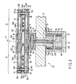
- FIG. 3 is a sectional view showing the transfer apparatus shown in FIG. 1 ;
- FIG. 4 is a sectional view showing the internal structure of a rotary base in the transfer apparatus shown in FIG. 1 ;
- FIG. 5 is a perspective view showing a state of a transfer apparatus according to a second embodiment of the present invention wherein two arm mechanisms are contracted;
- FIG. 6 is a plan view showing a state of the transfer apparatus shown in FIG. 5 wherein one arm mechanism is extended;
- FIG. 7 is a partially cutaway view showing the transfer apparatus shown in FIG. 5 ;
- FIGS. 8A to 8D are views schematically showing a series of operating states of the transfer apparatus shown in FIG. 5 ;
- FIG. 9 is a plan view showing a state of a transfer apparatus according to a third embodiment of the present invention wherein two arm mechanisms are contracted;
- FIG. 10 is a plan view showing a state of the transfer apparatus shown in FIG. 9 wherein one arm mechanism is extended;
- FIG. 11 is a partially cutaway view mainly showing the link mechanism portion of the transfer apparatus shown in FIG. 9 ;
- FIG. 12 is a plan view showing a state of a transfer apparatus according to a fourth embodiment of the present invention wherein two arm mechanisms are contracted;
- FIG. 13 is a side view showing the transfer apparatus shown in FIG. 12 ;
- FIG. 14 is a plan view showing a state of the transfer apparatus shown in FIG. 12 wherein one arm mechanism is extended;
- FIG. 15 is a plan view showing a state of a transfer apparatus according to a fifth embodiment of the present invention wherein one arm mechanism is extended;
- FIG. 16 is a partially cutaway view of the transfer apparatus shown in FIG. 15 to explain the coupled state of a linear motor, used as the second driving source, with a link mechanism;
- FIG. 17 is a plan view showing a state of a transfer apparatus according to a sixth embodiment of the present invention wherein two arm mechanisms are contracted;
- FIG. 18 is a plan view showing a state of the transfer apparatus shown in FIG. 17 wherein one arm mechanism is extended;
- FIG. 19 is a partially cutaway view showing the transfer apparatus shown in FIG. 17 ;
- FIGS. 20A to 20G are views schematically showing a series of operating states of the transfer apparatus shown in FIG. 17 ;
- FIG. 21 is a plan view showing a state of a transfer apparatus according to a seventh embodiment of the present invention wherein two arm mechanisms are contracted;
- FIG. 22 is a plan view showing a state of a transfer apparatus according to an eighth embodiment of the present invention wherein two arm mechanisms are contracted;
- FIG. 23 is a perspective view showing a state of the transfer apparatus shown in FIG. 22 wherein one arm mechanism is extended;
- FIGS. 24A to 24E are views schematically showing a series of operating states of the transfer apparatus shown in FIG. 12 ;
- FIG. 25 is a graph showing the results of a comparative experiment of apparatuses according to the seventh and eighth embodiments which are formed with the same specifications except for a link mechanism;
- FIG. 26 is an enlarged sectional view showing a driving mechanism according to an embodiment of the present invention.
- FIG. 27 is a view for explaining the positional relationship between a detection pattern and a reflection member, which is a main part of the driving mechanism shown in FIG. 26 ;
- FIG. 28 is a plan view showing a state wherein the detection pattern shown in FIG. 27 is linearly developed
- FIG. 29 is a perspective view showing a case wherein an entire outer driving shaft is formed as a detection pattern
- FIG. 30 is a developed view showing a detection pattern of a case wherein a detection structure is used as a position sensor
- FIG. 31 is an enlarged sectional view showing a modification of the driving mechanism shown in FIG. 26 ;
- FIGS. 32A to 32D are plan views respectively showing states wherein examples of a detection pattern used in the driving mechanism shown in FIG. 31 are linearly developed.
- FIG. 33 is a perspective view showing an example of a conventional transfer apparatus.
- FIG. 1 is a plan view showing a state of a transfer apparatus according to a first embodiment of the present invention wherein two arm mechanisms are contracted.
- FIG. 3 is a sectional view showing the transfer apparatus shown in FIG. 1 .
- a transfer apparatus 20 incorporates a rotary base 24 rotatably supported by a base 22 (see FIG. 3 ).
- a pair of arm mechanisms i.e., a first arm mechanism 26 and a second arm mechanism 28 , are supported by the rotary base 24 , so that they can pivot, bend, and stretch.
- a link mechanism 30 is disposed to selectively bend or stretch the first and second arm mechanisms 26 and 28 .
- a first driving source 32 (see FIG. 3 ) is disposed to rotatably drive the rotary base 24 .
- a second driving source 34 (see FIG. 3 ) is disposed to drive the link mechanism 30 to swingably pivot, so as to bend or stretch the first and second arm mechanisms 26 and 28 .
- the base 22 is formed of the bottom plate or the like of a transfer chamber which is disposed in, e.g., a cluster tool type semiconductor processing system.
- the interior of the transfer chamber is maintained in a vacuum state, and a plurality of process chambers (not shown) are connected to the transfer chamber to surround it.
- Driving shafts 38 and 40 which are coaxial are inserted in a through hole 36 formed in the base 22 .
- a motor box 44 comprising a hollow box is hermetically attached to the lower surface of the base 22 through a seal member 42 such as an O-ring.
- the motor box 44 accommodates the first and second driving sources 32 and 34 .
- the first and second driving sources 32 and 34 comprise, e.g., stepping motors (pulse motors), and are constituted by a stator 32 A and a rotor 32 B, and a stator 34 A and a rotor 34 B, respectively.
- the rotor 32 B of the first driving source 32 is coupled to the hollow (pipe-like) outer driving shaft 38 .
- the rotor 34 B of the second driving source is coupled to the inner driving shaft 40 .
- a bearing 46 is interposed between the two driving shafts 38 and 40 to rotatably support them.
- the outer driving shaft 38 is rotatably supported on the base 22 side through a bearing (not shown) which uses a magnetic fluid seal.
- the first and second driving sources 32 and 34 , the two driving shafts 38 and 40 , and the like constitute part of a driving mechanism (to be described later).
- the rotary base 24 is disposed at the upper end portions of the two driving shafts 38 and 40 .
- the rotary base 24 has a predetermined width and a hollow interior to extend radially (horizontally) by a predetermined length.
- the upper end of the outer driving shaft 38 is directly coupled and fixed to the rotary base 24 .
- the driving shaft 38 and rotary base 24 rotate integrally.
- the upper portion of the inner driving shaft 40 extends through the rotary base 24 .
- the driving shaft 40 is supported on the rotary base 24 through a bearing 48 , so the driving shaft 40 and rotary base 24 are rotatable. Accordingly, the inner driving shaft 40 serves as a pivot center C 1 of the entire transfer apparatus.
- Two fixed shafts 50 and 52 are attached and fixed upright to the upper surface of the proximal end portion side of the rotary base 24 to be spaced apart from each other by a predetermined distance.
- the first and second arm mechanisms 26 and 28 are rotatably attached to the fixed shafts 50 and 52 , respectively.
- the first arm mechanism 26 mainly comprises a hollow proximal end arm 26 A, a hollow intermediate arm 26 B, and a pick 26 C on which a wafer W is to be actually placed and held.
- the proximal end portion of the proximal end arm 26 A is rotatably supported by the fixed shaft 50 through a bearing 50 A.
- a large pulley 54 is fixed to the fixed shaft 50 to be integral with it.
- a rotary shaft 56 is disposed to extend upward in the distal end portion of the proximal end arm 26 A to be rotatable through a bearing 56 A.
- a small pulley 58 is fixed to the rotary shaft 56 and rotates together with it.
- a coupling belt 60 is looped between the small pulley 58 and large pulley 54 to transmit power.
- the ratio in diameter of the small pulley 58 to the large pulley 54 is 1:2.
- the small pulley 58 rotates with a rotation angle twice that of the large pulley 54 .
- the upper end portion of the rotary shaft 56 is disposed to extend through the proximal end portion of the intermediate arm 26 B.
- the upper end of the rotary shaft 56 is fixed to the upper surface of the intermediate arm 26 B.
- the intermediate arm 26 B rotates together with the rotary shaft 56 .
- the rotary shaft 56 rotatably supports a small pulley 62 through a bearing 56 B.
- the small pulley 62 is fixed to the upper end of a hollow fixed shaft 64 .
- the rotary shaft 56 extends in the fixed shaft 64 to be coaxial with it.
- the fixed shaft 64 has a predetermined length, and extends downward through the intermediate arm 26 B.
- the lower end of the fixed shaft 64 is fixed to the upper surface of the proximal end arm 26 A to be integral with it.
- a bearing 56 C is interposed between the rotary shaft 56 and fixed shaft 64 .
- the fixed shaft 64 is rotatably supported by the intermediate arm 26 B through a bearing 64 A.
- a rotary shaft 66 is rotatably supported at the distal end portion of the intermediate arm 26 B through a bearing 66 A.
- the upper end portion of the rotary shaft 66 extends upward to project externally.
- the proximal end portion of the pick 26 C is disposed to be fixed to the upper end portion of the projecting rotary shaft 66 .
- a large pulley 68 is fixed to the rotary shaft 66 .
- a coupling belt 70 is looped between the large pulley 68 and small pulley 62 to transmit power.
- the ratio in diameter of the small pulley 62 to the large pulley 68 is 1:2.
- the large pulley 68 rotates with a rotation angle 1 ⁇ 2 time that of the small pulley 62 .
- the second arm mechanism 28 has the same arrangement as that of the first arm mechanism 26 except that it is axial-symmetrical. More specifically, the second arm mechanism 28 mainly comprises a hollow proximal end arm 28 A, a hollow intermediate arm 28 B, and a pick 28 C on which a wafer W is to be actually placed and held.
- the proximal end portion of the proximal end arm 28 A is rotatably supported by the fixed shaft 52 through a bearing 52 A.
- a large pulley 74 is fixed to the fixed shaft 52 to be integral with it.
- a rotary shaft 76 is disposed to extend upward in the distal end portion of the proximal end arm 28 A to be rotatable through a bearing 76 A.
- a small pulley 78 is fixed to the rotary shaft 76 and rotates together with it.
- a coupling belt 80 is looped between the small pulley 78 and large pulley 74 to transmit power.
- the ratio in diameter of the small pulley 78 to the large pulley 74 is 1:2.
- the small pulley 78 rotates with a rotation angle twice that of the large pulley 74 .
- the upper end portion of the rotary shaft 76 is disposed to extend through the proximal end portion of the intermediate arm 28 B.
- the upper end of the rotary shaft 76 is fixed to the upper surface of the intermediate arm 28 B.
- the intermediate arm 28 B rotates together with the rotary shaft 76 .
- the rotary shaft 76 rotatably supports a small pulley 82 through a bearing 76 B.
- the small pulley 82 is fixed to the upper end of a hollow fixed shaft 84 .
- the rotary shaft 76 extends in the fixed shaft 84 to be coaxial with it.
- the fixed shaft 84 has a predetermined length.
- the fixed shaft 84 extends downward through the intermediate arm 28 B.
- the lower end of the fixed shaft 84 is fixed to the upper surface of the proximal end arm 28 A to be integral with it.
- a bearing 76 C is interposed between the rotary shaft 76 and fixed shaft 84 .
- the fixed shaft 84 is rotatably supported by the intermediate arm 28 B through a bearing 84 A.
- a rotary shaft 86 is rotatably supported at the distal end portion of the intermediate arm 28 B through a bearing 86 A.
- the upper end portion of the rotary shaft 86 extends upward to project externally.
- the proximal end portion of the pick 26 C is disposed to be fixed to the upper end portion of the projecting rotary shaft 86 .
- a large pulley 88 is fixed to the rotary shaft 86 .
- a coupling belt 90 is looped between the large pulley 88 and small pulley 82 to transmit power.
- the ratio in diameter of the small pulley 82 to the large pulley 88 is 1:2.
- the large pulley 88 rotates with a rotation angle 1 ⁇ 2 time that of the small pulley 82 .
- the two picks 26 C and 28 C are arranged on one plane (horizontal plane).
- the respective picks 26 C and 28 C advance in different directions, and an open angle ⁇ defined by them is set to, e.g., about 60°, although depending on the size of the wafer W.
- the open angle ⁇ is set within a range of, e.g., 60° to 180° (exclusive) such that the wafers do not interfere.
- the link mechanism 30 mainly comprises a driving link 92 and two driven links 94 A and 94 B.
- the driving link 92 is pivotally driven by the second driving source 34 (see FIG. 3 ).
- the driven links 94 A and 94 B are coupled to the driving link 92 .
- the driving link 92 is pivotally supported by the rotary base 24 .
- FIG. 4 is a sectional view showing the internal structure of the rotary base 24 in the transfer apparatus shown in FIG. 1 .
- a rotary shaft 96 is rotatably disposed at the distal end portion of the rotary base 24 through a bearing 96 A.
- a driven pulley 98 is fixed around the rotary shaft 96 .
- a driving pulley 100 is fixed around the driving shaft 40 in the rotary base 24 .
- a coupling belt 102 is looped between the driving pulley 100 and driven pulley 98 to transmit the power of the second driving source 34 .
- the driving pulley 100 , driven pulley 98 , and coupling belt 102 form a power transmission mechanism.
- the upper end portion of the rotary shaft 96 projects upward from the rotary base 24 .
- the proximal end portion of the driving link 92 is coupled to the upper end portion of the rotary shaft 96 , so the driving link 92 and rotary shaft 96 rotate integrally. Therefore, when the driving shaft 40 is rotated clockwise and counterclockwise, the driving link 92 also pivots clockwise and counterclockwise.
- the driving link 92 has a predetermined length.
- the proximal end portions of the two driven links 94 A and 94 B are rotatably disposed at the distal end portion of the driving link 92 side by side through respective support pins 104 A and 104 B and bearings (not shown).
- the driven links 94 A and 94 B have predetermined lengths.
- the distal end portion of one driven link 94 A is rotatably coupled to the upper surface at the central portion of the proximal end arm 26 A of the first arm mechanism 26 through a support pin 106 A and a bearing 106 B (see FIG. 3 ).
- the distal end portion of the other driven link 94 B is rotatably coupled to the upper surface at the central portion of the proximal end arm 28 A of the second arm mechanism 28 through a support pin 108 A and a bearing 108 B (see FIG. 3 ).
- FIG. 2 is a plan view showing a state of the transfer apparatus shown in FIG. 1 wherein one arm mechanism is extended. More specifically, when the driving link 92 is rotated through a predetermined angle in one direction, one pick 26 C advances largely, while the other pick 28 C retreats only by a short distance. When the driving link 92 is rotated through a predetermined angle in the other direction, the respective picks 26 C and 28 C operate in the opposite manner to that described above. More specifically, when the link mechanism 30 is rotated clockwise and counterclockwise, the first and second arm mechanisms 26 and 28 are bent or stretched selectively.
- the transfer apparatus 20 when the transfer apparatus 20 is to be set in a predetermined direction, the first and second driving sources 32 and 34 shown in FIG. 3 are rotated in synchronism with each other. Then, the rotary base 24 pivots to face in a predetermined direction. The first and second arm mechanisms 26 and 28 in the folded state (contracted state) thus face in predetermined directions.
- one pick e.g., the pick 26 C
- the second driving source 34 is rotated in a predetermined direction through a predetermined angle or at a predetermined rotational amount.
- the rotational driving force is transmitted to the rotary shaft 96 to rotate it through the driving shaft 40 , driving pulley 100 , coupling belt 102 , and driven pulley 98 .
- the driving link 92 of the link mechanism 30 which is integrally coupled to the rotary shaft 96 rotates as indicated by an arrow A in FIG. 2 .
- the driven link 94 A connected to the driving link 92 is pushed out obliquely as indicated by an arrow B.
- the distal end portion of the driven link 94 A is coupled to the proximal end arm 26 A of the first arm mechanism 26 .
- the proximal end arm 26 A rotates about the fixed shaft 50 (see FIG. 3 ) as a fulcrum as indicated by an arrow C (see FIG. 2 ).
- the large pulley 54 in the proximal end arm 26 A rotates relatively (actually, the large pulley 54 does not but the proximal end arm 26 A rotates).
- This rotational driving force is transmitted to the intermediate arm 26 B through the coupling belt 60 and small pulley 58 and then to the rotary shaft 66 through the small pulley 62 , coupling belt 70 , and large pulley 68 .
- the proximal end arm 26 A, intermediate arm 26 B, and pick 26 C in the folded state extend as shown in FIG. 2 .
- the pick 26 C advances linearly as indicated by an arrow D while facing in the same direction.
- the pick 26 C can be inserted in a predetermined process chamber (not shown).
- the picks 26 C and 28 C of the first and second arm mechanisms 26 and 28 advance or retreat respectively along line segments L 1 and L 2 which extend through a rotation center C 1 of the entire apparatus.
- the apparatus operates in the above manner.
- the exchange operation of the wafer W can be performed more swiftly than with the conventional transfer apparatus. More specifically, after a processed wafer W is unloaded, if the entire transfer apparatus 20 is pivoted through the pick open angle ⁇ e.g., 60°, the other pick which holds an unprocessed wafer W can be directed toward the process chamber. With one pick holding the wafer W and the other pick being empty, when the empty pick is to be advanced or retreated, the moving amount of the pick that holds the wafer W is small, as described above. Therefore, even if the empty pick is advanced or retreated at high speed, the wafer W will not drop from the other pick. As a result, the exchange operation of the wafer W can be performed more swiftly.
- FIG. 5 is a perspective view showing a state of a transfer apparatus according to a second embodiment of the present invention wherein two arm mechanisms are contracted.
- FIG. 6 is a plan view showing a state of the transfer apparatus shown in FIG. 5 wherein one arm mechanism is extended.
- FIG. 7 is a partially cutaway view showing the transfer apparatus shown in FIG. 5 .
- the second and first embodiments are different in the following respects. Namely, in the first embodiment, the proximal end portions of the first and second arm mechanisms 26 and 28 are supported on the rotary base 24 pivotally by two different shafts, i.e., the fixed shafts 50 and 52 , respectively. In the second embodiment, the proximal end portions of first and second arm mechanisms 26 and 28 are pivotally supported by one fixed shaft. In the first embodiment, the picks 26 C and 28 C are arranged on one plane to face in different directions. In the second embodiment, picks 26 C and 28 C are overlapped vertically and face in one direction. The state wherein the picks 26 C and 28 C are overlapped vertically is a structure that is common in other embodiments to be described hereinafter.
- one fixed shaft 110 is fixed on a rotary base 24 to extend upright.
- the fixed shaft 110 is longer than each of the fixed shafts 50 and 52 (see FIG. 3 ) of the first embodiment.
- the fixed shaft 110 is disposed to be positionally displaced transversely from a driving shaft 38 which pivots the rotary base 24 . This is the same as in the first embodiment.
- a large pulley 54 of the first arm mechanism 26 and a large pulley 74 of the second arm mechanism 28 are fixed to one fixed shaft 110 to line up vertically.
- a proximal end arm 26 A of the first arm mechanism 26 and a proximal end arm 28 A of the second arm mechanism 28 are disposed about the large pulleys 54 and 74 as the centers.
- the lengths of fixed shafts 64 and 84 are set slightly long.
- the fixed shaft 64 couples the proximal end arm 26 A to an intermediate arm 26 B.
- the fixed shaft 84 couples the proximal end arm 28 A to an intermediate arm 28 B.
- the distal end portions of the two driven links 94 A and 94 B of the link mechanism 30 are rotatably supported on the upper surface sides of the proximal end arms 26 A and 28 B (see FIG. 3 ).
- the height levels of the proximal end arms 26 A and 28 A are different, as shown in FIG. 7 . Therefore, the distal end portion of one driven link 94 A is rotatably supported on the lower surface side of the proximal end arm 26 A.
- the distal end portion of the other driven link 94 B is rotatably supported on the upper surface side of the proximal end arm 28 A, in the same manner as in the first embodiment.
- the two picks 26 C and 28 C can advance and retreat in one direction although their heights are different.
- a Z-axis moving mechanism (not shown) which moves the entire apparatus in the vertical direction (Z direction) is disposed.
- FIGS. 8A to 8D are views schematically showing a series of operating states of the transfer apparatus shown in FIG. 5 .
- FIG. 8A shows a state wherein the second arm mechanism 28 is extended and the first arm mechanism 26 is contracted.
- the link mechanism 30 is pivoted in the opposite direction
- the second arm mechanism 28 starts to contract as shown in FIG. 8B
- the first arm mechanism 26 starts to extend.
- the pick 26 C of the first arm mechanism 26 slightly retreats temporarily.
- the second arm mechanism 28 When the link mechanism 30 is further pivoted in the opposite direction, the second arm mechanism 28 further continues contracting while the first arm mechanism 26 continues extending, as shown in FIG. 8C . At this time point, the two picks 26 C and 28 C overlap vertically. When the link mechanism 30 is further pivoted in the opposite direction, the second arm mechanism 28 contracts the most while the first arm mechanism 26 extends the most, as shown in FIG. 8D .
- the two picks 26 C and 28 C are exchanged in this manner.
- the entire apparatus is slightly moved upward or downward at the time point shown in FIG. 8C to adjust the height levels of the two picks 26 C and 28 C.
- the two, first and second arm mechanisms 26 and 28 respectively having the vertically overlapping two picks 26 C and 28 C can be bent or stretched by only two motors, i.e., the first and second driving sources 32 and 34 . Therefore, the structure of the apparatus can be simplified and the cost can be decreased.
- FIG. 9 is a plan view showing a state of a transfer apparatus according to a third embodiment of the present invention wherein two arm mechanisms are contracted.
- FIG. 10 is a plan view showing a state of the transfer apparatus shown in FIG. 9 wherein one arm mechanism is extended.
- FIG. 11 is a partially cutaway view mainly showing the link mechanism portion of the transfer apparatus shown in FIG. 9 .
- the third embodiment in the same manner as in the second embodiment, picks 26 C and 28 C overlap vertically, and the proximal end portions of first and second arm mechanisms 26 and 28 are coaxial and pivotal.
- the third embodiment is largely different from the first and second embodiments in the following respect. Namely, the driving link 92 (see FIGS. 1 and 6 ) of the link mechanism 30 is replaced by a small link mechanism 112 , i.e., which is small. In other words, as apparent from comparison with FIG. 4 , in place of the driving link 92 shown in FIG. 4 , the small link mechanism 112 is disposed as shown in FIG. 11 .
- the small link mechanism 112 comprises a first link lever 114 and a second link lever 116 .
- the two levers 114 and 116 are coupled to each other, so that they can bend and stretch. More specifically, the first link lever 114 is hollow.
- the upper end portion of a rotary shaft 96 at the distal end portion of a rotary base 24 is disposed to extend through the proximal end portion of the first link lever 114 .
- the upper end of the rotary shaft 96 is fixed inside the upper surface of the first link lever 114 .
- the first link lever 114 and rotary shaft 96 rotate integrally.
- a large pulley 120 is rotatably disposed in the rotary shaft 96 in the first link lever 114 through a bearing 118 .
- a hollow outer shaft 122 is disposed around the rotary shaft 96 to be coaxial with it. The lower end of the outer shaft 122 is fixed to the upper surface of the rotary base 24 . The upper end of the outer shaft 122 is fixed to the large pulley 120 .
- a bearing 124 A is interposed between the rotary shaft 96 and outer shaft 122 .
- a bearing 124 B is interposed between the outer shaft 122 and the extending portion of the first link lever 114 .
- the two shafts 96 and 122 are thus rotatable.
- a rotary shaft 128 is rotatably disposed at the distal end portion of the first link lever 114 through a bearing 126 .
- a small pulley 130 is fixed on the rotary shaft 128 .
- a coupling belt 132 is looped between the small pulley 130 and large pulley 120 to transmit driving power.
- the ratio in diameter of the small pulley 130 to the large pulley 120 is set to 1:2.
- the upper end portion of the rotary shaft 128 projects upward.
- the proximal end portion of the second link lever 116 is fixed to the projecting upper end portion of the rotary shaft 128 .
- the rotary shaft 128 and second link lever 116 rotate integrally.
- a fixed shaft 133 is disposed at the distal end portion of the second link lever 116 to extend upright.
- the proximal end portion of one driven link 94 A is rotatably attached to the lower portion of the fixed shaft 133 through a bearing 134 A.
- the driven link 94 A bends or stretches the first arm mechanism 26 .
- the proximal end portion of the other driven link 94 B is rotatably attached to the upper portion of the fixed shaft 133 through a bearing 134 B.
- the driven link 94 B bends or stretches the second arm mechanism 28 .
- the distal end portions of the two driven links 94 A and 94 B are rotatably supported on the upper surface sides of proximal end arms 26 A and 28 A, respectively.
- the distal end portions of the two driven links 94 A and 94 B may be rotatably supported on the lower surface sides of the proximal end arms 26 A and 26 B, or on the upper and lower surface sides of the proximal end arms 26 A and 26 B.
- the small link mechanism 112 bends or stretches.
- a fulcrum P 1 at the proximal end portions of the two driven links 94 A and 94 B of a link mechanism 30 reciprocates on a straight line 140 in FIG. 10 .
- the first and second arm mechanisms 26 and 28 extend and contract alternately.
- the two, first and second arm mechanisms 26 and 28 respectively having the vertically overlapping two picks 26 C and 28 C can be bent or stretched by only two motors, i.e., the first and second driving sources 32 and 34 . Therefore, the structure of the apparatus can be simplified and the cost can be decreased.
- FIG. 12 is a plan view showing a state of a transfer apparatus according to a fourth embodiment of the present invention wherein two arm mechanisms are contracted.
- FIG. 13 is a side view showing the transfer apparatus shown in FIG. 12 .
- FIG. 14 is a plan view showing a state of the transfer apparatus shown in FIG. 12 wherein one arm mechanism is extended.
- picks 26 C and 28 C overlap vertically, and a small link mechanism 112 is disposed in a link mechanism 30 , in the same manner as in the third embodiment.
- the fourth embodiment is different from the third embodiment in the following respect. That is, first and second arm mechanisms 26 and 28 are supported on a rotary base 24 not by one fixed shaft, but respectively, rotatably by two fixed shafts 50 and 52 , in the same manner as in the first embodiment.
- the first arm mechanism 26 comprises a proximal end arm 26 A, an intermediate arm 26 B, a pick 26 C, and a proximal end portion 26 D of the pick 26 C.
- the second arm mechanism 28 comprises a proximal end arm 28 A, an intermediate arm 28 B, a pick 28 C, and a proximal end portion 28 D of the pick 28 C.
- the second arm mechanism 28 is arranged above the first arm mechanism 26 , so the two vertically overlapping picks 26 C and 28 C will not interfere with each other.
- the fourth embodiment can exhibit the same function and effect as those of the third embodiment. Namely, the two, first and second arm mechanisms 26 and 28 respectively having the vertically overlapping two picks 26 C and 28 C can be bent or stretched by only two motors, i.e., first and second driving sources 32 and 34 . Therefore, the structure of the apparatus can be simplified and the cost can be decreased.
- FIG. 15 is a plan view showing a state of a transfer apparatus according to a fifth embodiment of the present invention wherein one arm mechanism is extended.
- FIG. 16 is a partially cutaway view of the transfer apparatus shown in FIG. 15 to explain the coupled state of a linear motor, used as a second driving source, with a link mechanism.
- the fifth embodiment has substantially the same arrangement as that of the third embodiment but is different from it mainly in the following respects. More specifically, in the third embodiment, the small link mechanism 112 is coupled to the proximal end portions of the two driven links 94 A and 94 B of the link mechanism 30 , as shown in FIG. 10 . When the small link mechanism 112 is bent or stretched, the proximal end portions of the driven links 94 A and 94 B reciprocate along the straight line 140 . In contrast to this, in the fifth embodiment, a linear motor 142 is disposed, as shown in FIGS. 15 and 16 . The linear motor 142 is capable of accurate position control along a straight line 140 . The linear motor 142 serves as the second driving source 34 shown in FIG. 3 .
- a support rod 144 is attached and fixed to a moving body 142 A of the linear motor 142 .
- a fixed shaft 133 is disposed on the support rod 144 to extend upright.
- the proximal end portions of driven links 94 A and 94 B are rotatably attached and fixed to the fixed shaft 133 respectively through bearings 134 A and 134 B, in the same manner as that described with reference to FIG. 11 .
- the linear motor 142 is used as the second driving source. More specifically, the proximal end portion sides of the two driven links 94 A and 94 B of a link mechanism 30 are rotatably supported on the moving body 142 A side of the linear motor 142 directly, so as to linearly move the moving body 142 A.
- the second driving source 34 in the motor box 44 , and the driving pulley 100 , driven pulley 98 , and coupling belt 102 in the rotary base 24 which are described with reference to FIGS. 3 and 4 , become unnecessary. Hence, the arrangement of the apparatus can be more simplified accordingly.
- first and second arm mechanisms 26 and 28 can be bent or stretched in the same manner as in the third embodiment (see FIG. 10 ).
- the two, first and second arm mechanisms 26 and 28 respectively having vertically overlapping two picks 26 C and 28 C can be bent or stretched by only two motors, i.e., a first driving source 32 and the linear motor 142 serving as the second driving source. Therefore, the structure of the apparatus can be simplified and the cost can be decreased.
- FIG. 17 is a plan view showing a state of a transfer apparatus according to a sixth embodiment of the present invention wherein two arm mechanisms are contracted.
- FIG. 18 is a plan view showing a state of the transfer apparatus shown in FIG. 17 wherein one arm mechanism is extended.
- FIG. 19 is a partially cutaway view showing the transfer apparatus shown in FIG. 17 .
- the sixth embodiment has an arrangement similar to that of the fourth embodiment but is different from the fourth embodiment mainly in the following respects. More specifically, according to the fourth embodiment, the driving power of the second driving source 34 is transmitted to two driven links 94 A and 94 B through a driving pulley 100 of the rotary base 24 , a coupling belt 102 , a driven pulley 98 , and the small link mechanism 112 . In contrast to this, according to the sixth embodiment, the proximal end portions of two driven links 94 A and 94 B are coupled to a driving shaft 40 of a second driving source 34 through the driving link 92 of the first embodiment shown in FIG. 1 .
- the proximal end portion of the driving link 92 is directly coupled and fixed to the driving shaft 40 of the second driving source 34 .
- the driving link 92 is rotatably supported at the rotation center portion of a rotary base 24 .
- support pins 104 A and 104 B are disposed at the distal end portion of the driving link 92 to extend upright.
- the proximal end portions of the two driven links 94 A and 94 B are rotatably supported respectively by the support pins 104 A and 104 B through bearings 150 .
- FIG. 19 shows only one driven link 94 A.
- first and second arm mechanisms 26 and 28 are rotatably supported on the rotary base 24 by different shafts to be parallel to each other in the same manner as in the fourth embodiment.
- Two picks 26 C and 28 C are arranged to vertically overlap, and bent or stretched in the same direction.
- Horizontally extending coupling projections 152 and 154 are disposed at substantially the central portions of respective proximal end arms 26 A and 28 A.
- the distal end portions of the driven links 94 A and 94 B are respectively, pivotally supported by the auxiliary projections 152 and 154 through bearings (not shown).
- the apparatus operates substantially in the same manner as in the fourth embodiment.
- the driving link 92 pivots about the driving shaft 40 of the second driving source 34 as the center.
- the proximal end portions of the two driven links 94 A and 94 B respectively reciprocate along arcuate loci about the driving shaft 40 as the center, unlike in the fourth embodiment.
- the first and second arm mechanisms 26 and 28 are accordingly bent or stretched in opposite directions.
- FIGS. 20A to 20G are views schematically showing a series of operating states of the transfer apparatus shown in FIG. 17 .
- FIG. 20A shows a state wherein the first arm mechanism 26 is extended while the second arm mechanism 28 is contracted. In this state, when the driving link 92 is rotated to pivot a link mechanism 30 in an opposite direction, the first arm mechanism 26 starts to contract accordingly, as shown in FIG. 20B , while the second arm mechanism 28 hardly moves.
- the driving link 92 is further rotated to pivot the link mechanism 30 in the opposite direction.
- the first arm mechanism 26 keeps the contracted state while the second arm mechanism 28 gradually extends to reach the most extended state, as shown in FIGS. 20E to 20G .
- the two picks 26 C and 28 C are exchanged in this manner.
- the entire apparatus is slightly moved upward or downward to adjust the height levels of the two picks 26 C and 28 C.
- the two, first and second arm mechanisms 26 and 28 respectively having the vertically overlapping two picks 26 C and 28 C can be bent or stretched by only two motors, i.e., a first driving source 32 and the second driving source 34 . Therefore, the structure of the apparatus can be simplified and the cost can be decreased.
- a power transmission mechanism comprising a pulley, a coupling belt, and the like becomes unnecessary, and the arrangement of the apparatus can accordingly be more simplified.
- FIG. 21 is a plan view showing a state of a transfer apparatus according to a seventh embodiment of the present invention wherein two arm mechanisms are contracted.
- the connection state in the vertical direction of the first and second driving sources, rotary base, and first and second arm mechanisms of this apparatus is similar to that shown in FIG. 3 .
- the connection state in the vertical direction of the first and second driving sources, rotary base, and one arm mechanism of this apparatus is similar to that shown in FIG. 19 .
- the seventh embodiment is similar to the first embodiment.
- Proximal end arms 26 A and 28 A of first and second arm mechanisms 26 and 28 are supported on a rotary base 24 (circular in FIG. 21 ) to be rotatable about shafts, which are spaced apart from each other on one plane, as centers.
- Picks 26 C and 28 C of the first and second arm mechanisms 26 and 28 are arranged on one plane to face in different directions.
- the open angle of the picks 26 C and 28 C is set within a range of 60° to 180°.
- the pivot shaft of a driving link 92 of a link mechanism 30 is arranged to be coaxial with the rotary shaft of the rotary base 24 , unlike in the first embodiment.
- the operations of the first and second arm mechanisms 26 and 28 of the seventh embodiment are those of the first and sixth embodiments combined together. More specifically, in the initial state shown in FIG. 21 , both the first and second arm mechanisms 26 and 28 are contracted. In this state, assume that the second arm mechanism 28 extends to advance the pick 28 C. In this case, the first arm mechanism 26 substantially maintains its contracted state. However, as the rotary base 24 rotates, the angle formed by the proximal end arm 26 A and an intermediate arm 26 B enlarges to retreat the pick 26 C. These operations are similar to those shown in FIGS. 20D to 20G . In this case, however, the pick 26 C does not keep facing forward, but faces to an oblique direction, as shown in FIG. 2 .
- an advantage can be obtained that when compared to the first embodiment, the entire structure becomes more compact. According to the seventh embodiment, an advantage can be obtained that when compared to the sixth embodiment, the entire apparatus need not be lifted when switching between the first and second arm mechanisms 26 and 28 .
- FIG. 22 is a plan view showing a state of a transfer apparatus according to an eighth embodiment of the present invention wherein two arm mechanisms are contracted.
- FIG. 23 is a perspective view showing a state of the transfer apparatus shown in FIG. 22 wherein one arm mechanism is extended.
- the connection state in the vertical direction of the first and second driving sources, rotary base, and first and second arm mechanisms of this apparatus is similar to that shown in FIG. 3 .
- the connection state in the vertical direction of the first and second driving sources, rotary base, and one arm mechanism of this apparatus is similar to that shown in FIG. 19 .
- the eighth embodiment is similar to the seventh embodiment.
- Proximal end arms 26 A and 28 A of first and second arm mechanisms 26 and 28 are supported on a circular rotary base 24 to be rotatable about shafts, which are spaced apart from each other on one plane, as centers.
- Picks 26 C and 28 C of the first and second arm mechanisms 26 and 28 are arranged on one plane to face in different directions.
- the open angle of the picks 26 C and 28 C is set within a range of 60° to 180°.
- the pivot shaft of a driving link 92 of a link mechanism 30 is arranged to be coaxial with the rotary shaft of the rotary base 24 .
- two driven links 94 A and 94 B form a U shape, are arranged at different height levels, and are disposed to intersect each other. More specifically, as shown in FIG. 22 , the driven link 94 A coupled to the first arm mechanism 26 is axially supported by the driving link 92 on a side close to the second arm mechanism 28 across a center line CL 92 . Similarly, the driven link 94 B coupled to the second arm mechanism 28 is axially supported by the driving link 92 on a side close to the first arm mechanism 26 across the center line CL 92 .
- the center line CL 92 is a perpendicular bisector of a line segment CA-CB in an initial state where both the first and second arm mechanisms 26 and 28 are contracted.
- the line segment CA-CB connects centers CA and CB of the picks 26 C and 28 C of the first and second arm mechanisms 26 and 28 , respectively.
- FIGS. 24A to 24E are views schematically showing a series of operating states of the transfer apparatus shown in FIG. 12 .
- FIG. 24A shows the initial state where both the first and second arm mechanisms 26 and 28 are contracted. In this initial state, when the rotary base 24 is rotated counterclockwise, the second arm mechanism 28 extends to move the pick 28 C forward, while the first arm mechanism 26 substantially maintains its contracted state (see FIGS. 24B to 24E ). As the driven links 94 A and 94 B are arranged in the same manner as described above, the moving acceleration generated in the pick 26 C of the first arm mechanism 26 decreases.
- the reason for this will be described by way of line segments O-OA and O-OB.
- the line segment O-OA connects a pivot shaft O of the driving link 92 and a coupling point OA of the proximal end arm 26 A and second driven link 94 A.
- the line segment O-OB connects the pivot shaft O and a coupling point OB of the proximal end arm 28 A and second driven link 94 B.
- the transfer apparatus according to the eighth embodiment is formed in the following manner. Namely, the change amount of the line segment O-OA or O-OB including the coupling point OA or OB of that one of the first and second arm mechanisms 26 and 28 which is not extended (contraction side) should decrease. For example, in the operation example shown in FIGS.
- 24C shows a dead point state where three points, i.e., the pivot shaft O of the driving link 92 , the coupling point OA of the proximal end arm 26 A and second driven link 94 A, and a coupling point O 1 of the driving link 92 and driven link 94 A, line up on one straight line.
- the second arm mechanism 28 extends from the initial state where both the first and second arm mechanisms 26 and 28 contract.
- the first arm mechanism 26 changes between states via the dead point state (the state shown in FIG. 24C where the three points O, OA, and O 1 line up on one straight line). Therefore, the pick 26 C of the contracted-side first arm mechanism 26 moves slowly by retreating slightly at first and then advancing slightly. The stroke of the pick 26 C is also small. Assume that from the initial state where both the first and second arm mechanisms 26 and 28 contract, the first arm mechanism 26 extends. In this case as well, the pick 28 C of the second arm mechanism 28 operates similarly.
- the apparatuses according to the seventh and eighth embodiments were fabricated with the same specification except for the link mechanism.
- the two apparatuses were subjected to a comparative experiment. In this experiment, from the initial state where both the first and second arm mechanisms 26 and 28 contracted, the first arm mechanism 26 was extended. The arm strokes of the first and second arm mechanisms 26 and 28 at this time were measured.
- FIG. 25 is a graph showing the results of this comparative experiment.
- reference numerals L 71 and L 81 respectively denote the arm strokes of the first arm mechanisms 26 of the apparatuses according to the seventh and eighth embodiments.
- Reference numerals L 72 and L 82 respectively denote the arm strokes of the second arm mechanisms 28 of the apparatuses according to the seventh and eighth embodiments.
- the axis of abscissa represents the rotation angle (°) of the rotary base 24
- the axis of ordinate represents the arm stroke (mm).
- the arm stroke necessary for the first arm mechanism 26 is 600 mm.
- the rotary bases 24 must be rotated through about 70° and 80°, respectively.
- the arm stroke of the second arm mechanism 28 of the apparatus according to the seventh embodiment increases progressively until a maximal value of about 400 mm.
- the arm stroke of the second arm mechanism 28 of the apparatus according to the eighth embodiment takes a maximal value of about 100 mm when the rotary base 24 rotates through about 40°, and then decreases again.
- the pick of the other arm mechanism moves slowly. Also, the maximal value of the arm stroke of the pick of the other arm mechanism is small. Therefore, the moving acceleration generated in this pick decreases, and a wafer W on the pick does not positionally shift readily. As a result, the operation speed of the apparatus can be increased, thus increasing the throughput.
- each of the first and second arm mechanisms 26 and 28 one obtained by subjecting the surface of an aluminum alloy housing to a rigid sulfuric-acid anodized aluminum process can be employed.
- the housing is formed of an aluminum alloy, the arm mechanism can be suppressed from falling down by its own weight.
- the inertia generated when the arm mechanism is actuated can be decreased to improve the transfer accuracy of the arm mechanism.
- a magnetic field may be formed in the process chamber. If an aluminum alloy housing is employed, the arm mechanism can be prevented from being swung by the magnetic field.
- the anodized aluminum film is sufficiently impregnated with grease, so that the replenish service life of the grease can be prolonged.
- the first to eighth embodiments are exemplified by a case wherein the transfer apparatus is set in a vacuum atmosphere. Alternatively, the transfer apparatus may be set in an atmosphere under atmospheric pressure.
- the first to eighth embodiments are exemplified by a case wherein the semiconductor wafers are exchanged by loading and unloading them in and from the process chamber by the transfer apparatus. Alternatively, the transfer apparatus may be disposed midway along a wafer transfer path to which no process chamber is concerned directly.
- encoders absolute type or increment type
- a relative positional relationship between the respective driving shafts can be obtained by calculating output signals from the encoders.
- the encoders are provided in this manner, the entire structure of the driving mechanism becomes complicated to increase the cost. Spaces to set the encoders and the like are necessary, which leads to a bulky apparatus. Furthermore, wiring cords must be connected to the driving shafts to send the signals from the encoders and the like. Therefore, the driving shafts themselves cannot but have finite-rotary structures.
- an optical sensor is used to simplify the entire structure and allow easy recognition of the positional relationship in the rotational direction of the respective driving shafts relative to each other.
- the original point can be determined and the states of the first and second arm mechanisms can be checked.
- various states can be checked, e.g., a state wherein the two arm mechanisms are folded and contracted, a state wherein either one arm mechanism is extended to the maximum, and a state wherein even if the gate valve of the process chamber is closed, it will not interfere with the arm mechanism, thus causing no problem.
- FIG. 26 is an enlarged sectional view showing a driving mechanism according to an embodiment of the present invention.
- FIG. 27 is a view for explaining the positional relationship between a detection pattern and a reflection member, which is a main part of the driving mechanism shown in FIG. 26 .
- FIG. 28 is a plan view showing a state wherein the detection pattern shown in FIG. 27 is linearly developed.
- the driving mechanism to be described hereinafter can be used in all of the transfer apparatuses according to the first to eighth embodiments described above. A case will be described hereinafter wherein the driving mechanism is applied to the first embodiment shown in FIGS. 1 to 4 .
- a driving mechanism 160 incorporates a plurality of coaxial and rotatable hollow pipe-like driving shafts, i.e., the two driving shafts 38 and 40 in the example shown in FIG. 26 .
- the first and second driving sources 32 and 34 are respectively connected to the outer and inner driving shafts 38 and 40 .
- Connection of the driving shafts 38 and 40 includes not only a case wherein they are mechanically directly connected but also a case wherein they are connected in a noncontact manner as in magnetic connection.
- a light-emitting portion 162 emits detection light L 1 in the inner driving shaft 40 along the axial direction.
- the detection light L 1 is reflected by a reflection member 166 in a predetermined direction.
- the reflected detection light L 1 passes through a light-transmitting window 168 outward.
- a detection pattern 170 to be irradiated with the detection light L 1 is disposed on the inner surface of the outer driving shaft 38 .
- Reflected light L 2 from the detection pattern 170 is received by a light-receiving portion 164 along a route opposite to that of the detection light L 1 .
- a position detector 172 comprising a microcomputer or the like detects the positional relationship between the driving shafts 38 and 40 in the rotational direction on the basis of an output from the light-receiving portion 164 .
- the two hollow pipe-like driving shafts 38 and 40 are rotatably supported by a bearing 46 interposed between them.
- the inner driving shaft 40 is coupled to the second driving source 34 and is rotated clockwise and counterclockwise by the source.
- the outer driving shaft 38 is coupled to the first driving source 32 and rotated clockwise and counterclockwise by the source.
- the light-emitting portion 162 and light-receiving portion 164 are fixed side by side on the bottom portion side of the motor box 44 .
- the motor box 44 is a housing that accommodates the first and second driving sources 32 and 34 .
- an integral reflection type optical sensor can be used as the light-emitting portion 162 and light-receiving portion 164 .
- the light-receiving portion 164 emits the detection light L 1 along the axial direction of the hollow pipe-like inner driving shaft 40 .
- a laser beam which travels highly straightly is preferable, but diffused light may also be used instead.
- the wavelength of the detection light L 1 can be set in all bands including the infrared band, visible light band, and ultraviolet band.
- the reflection member 166 is formed of, e.g., a reflection mirror, and attached and fixed to the inner surface side of the inner driving shaft 40 inclinedly such that its reflection surface is at an angle of, e.g., 45°.
- the reflection member 166 reflects the detection light L 1 at a right angle in the radial direction of the inner driving shaft 40 .
- the light-transmitting window 168 comprising, e.g., a circular opening, is formed at that portion of the side wall of the inner driving shaft 40 on which the detection light L 1 reflected by the reflection member 166 is incident.
- the light-transmitting window 168 suffices as far as it can transmit the detection light L 1 .
- the detection light L 1 is transmitted through the side wall of the driving shaft 40 . Therefore, no opening need be formed in the driving shaft 40 , but the entire side wall serves as a light-transmitting window.
- the detection pattern 170 is disposed in the circumferential direction. As shown in FIG. 28 , the detection pattern 170 has a light-reflecting area 170 A which reflects the detection light L 1 and a light-absorbing area 170 B which absorbs the detection light L 1 .
- the two areas 170 A and 170 B have predetermined lengths.
- the first and second arm mechanisms 26 and 28 bend or stretch selectively.
- the length of the light-reflecting area 170 A is set to fall within a range (zone) where the first and second arm mechanisms 26 and 28 will not interfere with (collide against) a gate valve (not shown) even if the gate valve is closed.
- This gate valve partitions the transfer chamber and the process chamber arranged around the transfer chamber from each other, and is selectively opened and closed.
- the length of the light-absorbing area 170 B is set to fall within a range (zone) where the gate valve interferes with the first or second arm mechanism 26 or 28 .
- the position detector 172 can recognize the positions in the rotational direction of the two driving shafts 38 and 40 relative to each other on the basis of an output from the light-receiving portion 164 which receives the reflected light L 2 from the detection pattern 170 . The position detector 172 then can determine whether the gate valve can be closed. This determination result is transmitted to a host computer or the like which controls the overall operation of the semiconductor processing system.
- the inner driving shaft 40 is rotated clockwise and counterclockwise through a predetermined angle. This bends or stretches the first and second arm mechanisms 26 and 28 selectively to load and unload, e.g., a wafer, into and from the process chamber.
- the two driving shafts 38 and 40 are rotated through a predetermined angle in synchronism with each other. At this time, the first and second arm mechanisms 26 and 28 are entirely rotated in a desired direction while they are being maintained in the same bent or stretched posture.
- the light-emitting portion 162 emits the detection light L 1 in order to recognize the positional relationship in the rotational direction between the two driving shafts 38 and 40 .
- the detection light L 1 travels inside the inner driving shaft 40 in the axial direction and is reflected by the reflection member 166 to change its traveling direction by almost 90°.
- the detection light L 1 passes through the light-transmitting window 168 to irradiate the detection pattern 170 which is disposed on the inner surface of the outer driving shaft 38 along the circumferential direction.
- the detection light L 1 irradiates the light-reflecting area 170 A of the detection pattern 170 , it is reflected to form the reflected light L 2 .
- the reflected light L 2 travels along the optical path described above in the opposite direction and is received by the light-receiving portion 164 .
- the detection light L 1 irradiates the light-absorbing area 170 B, it is absorbed and does not form the reflected light L 2 .
- the position detector 172 which receives an output from the light-receiving portion 164 recognizes the positional relationship in the rotational direction between the two driving shafts 38 and 40 on the basis of the output.
- the light-emitting portion 162 and light-receiving portion 164 serve as a zone identification sensor. For example, if the light-receiving portion 164 does not receive the reflected light L 2 , the reflection surface of the reflection member 166 is directed to part of the zone of the light-absorbing area 170 B in FIG. 28 . This signifies that either one of the two arm mechanisms 26 and 28 is extended more than the predetermined length. In this case, if the gate valve is closed, interference (collision) may occur. Thus, it is prohibited to close the gate valve or to rotate the arm mechanisms 26 and 28 entirely.
- the reflection surface of the reflection member 166 is directed to part of the zone of the light-reflecting area 170 A in FIG. 28 .
- the first and second driving sources 32 and 34 comprise stepping motors or servo motors.
- the determination result of the position detector 172 can be used as a determination standard for the interlock function. For example, assume that the host computer is to perform a process of closing the gate valve in accordance with a software process. In this case, if the position detector 172 detects a signal “reflected light L 2 not received”, the arm mechanism interferes with the gate valves. Hence, interlocking can be performed with an electrical circuit configuration so as not to close the gate valve on the basis of the determination result of the position detector 72 .
- the detection pattern 170 is formed on the inner surface of the outer driving shaft 38 .
- that portion of the outer driving shaft 38 which opposes at least the light-transmitting window 168 may be entirely formed as the detection pattern 170 .
- FIG. 29 is a perspective view showing a case wherein the entire outer driving shaft 38 is formed as the detection pattern 170 .
- the light-reflecting area 170 A is set such that at least its inner wall surface is surface-polished to reflect light.
- the light-absorbing area 170 B is set such that at least its inner wall surface is subjected to a black anodized aluminum process (when the driving shaft 38 is made of aluminum) to absorb light.
- FIG. 30 is a developed view showing the detection pattern 170 of a case wherein the detection structure is used as a position sensor.
- the light-absorbing area 170 B is linearly formed at a predetermined portion of the detection pattern 170 to have a small width that the light-receiving portion 164 can barely recognize. This position serves as the original point. Accordingly, the remaining region forms the light-reflecting area 170 A.
- the relationship between the light-absorbing area 170 B and light-reflecting area 170 A may be reversed.
- the original point of the positions of the two driving shafts 38 and 40 relative to each other i.e., the original point of the two arm mechanisms 26 and 28
- a state can be set wherein the two arm mechanisms 26 and 28 both bend or stretch equally to be contracted, as shown in FIG. 1 .
- FIG. 31 is an enlarged sectional view showing a modification of the driving mechanism shown in FIG. 26 based on this point of view.
- FIGS. 32A to 32D are plan views respectively showing states wherein examples of the detection pattern used in the driving mechanism shown in FIG. 31 are linearly developed.
- an image sensor 180 comprising, e.g., a CCD camera, is arranged to recognize the image of the detection pattern 170 .
- an illumination member to illuminate this portion is desirably disposed.
- an illumination member 182 is disposed which can brighten a region having a certain area.
- the illumination member is an LED (light-emitting diode). Illumination light L 3 from the illumination member 182 illuminates part of the detection pattern 170 . When the detection pattern 170 is bright with external light, the illumination member 182 is not necessary.
- the position detector 172 can recognize different lightnesses, different colors, different figures, and the like. If the detection pattern 170 has a structure as shown in FIG. 28 or 30 , the light-reflecting area 170 A and light-absorbing area 170 B can be recognized in accordance with a difference in lightness. Also, the detection pattern 170 can be formed as shown in FIGS. 32A to 32D .
- the detection pattern 170 is divided into three regions, e.g., “black”, “gray”, and “white” regions. The three regions are recognized in accordance with a difference in lightness. These regions may be formed “gray” with different lightnesses.
- the detection pattern 170 is divided into three regions, e.g., red”, “blue”, and “yellow”. The three regions are identified in accordance with a difference in color.
- FIGS. 32C and 32D show the detection patterns 170 of cases where the detection structure is used as a position sensor.
- three different figures i.e., “ ⁇ ”, “ ⁇ ”, and “ ⁇ ”, are arranged.
- characters “ 1 ”, “ 2 ”, and “ 3 ” are arranged as figures.
- the three positions can be detected from a difference in figure.
- original point 1 , original point 2 , and original point 3 respectively correspond to the respective marks from the left. Desired bent or stretched states of the respective arm mechanisms 26 and 28 can be assigned to the respective original points 1 to 3 .
- the above driving mechanism is exemplified by a coaxial two-shaft structure.
- the present invention can also be applied to a case employing a driving mechanism having a three or more shafts.
- a semiconductor wafer is used as a target substrate.
- the present invention is not limited to this, but can also be applied to a case wherein a glass substrate, an LCD substrate, and the like are to be transferred.
- a transfer apparatus can be provided in which a base needs to be pivoted through only a small pivot angle when exchanging target substrates.
- a driving mechanism can be provided which can detect the positional relationship among a plurality of driving shafts relative to each other without using an encoder or the like.
Abstract
Description
Claims (29)
Applications Claiming Priority (5)
| Application Number | Priority Date | Filing Date | Title |
|---|---|---|---|
| JP2003-197689 | 2003-07-16 | ||
| JP2003197689 | 2003-07-16 | ||
| JP2004-009506 | 2004-01-16 | ||
| JP2004009506 | 2004-01-16 | ||
| PCT/JP2004/010178 WO2005008769A1 (en) | 2003-07-16 | 2004-07-09 | Transportation apparatus and drive mechanism |
Publications (2)
| Publication Number | Publication Date |
|---|---|
| US20060210387A1 US20060210387A1 (en) | 2006-09-21 |
| US7837425B2 true US7837425B2 (en) | 2010-11-23 |
Family
ID=34082310
Family Applications (1)
| Application Number | Title | Priority Date | Filing Date |
|---|---|---|---|
| US10/564,618 Active 2027-02-26 US7837425B2 (en) | 2003-07-16 | 2004-07-09 | Transportation apparatus and drive mechanism |
Country Status (5)
| Country | Link |
|---|---|
| US (1) | US7837425B2 (en) |
| EP (1) | EP1657743B1 (en) |
| JP (1) | JP5024411B2 (en) |
| KR (1) | KR100582697B1 (en) |
| WO (1) | WO2005008769A1 (en) |
Cited By (409)
| Publication number | Priority date | Publication date | Assignee | Title |
|---|---|---|---|---|
| US20080056856A1 (en) * | 2006-08-31 | 2008-03-06 | Brooks Automation, Inc. | Compact Processing Apparatus |
| US20090087288A1 (en) * | 2007-05-08 | 2009-04-02 | Brooks Automation Inc. | Substrate transport apparatus with multiple movable arms utilizing a mechanical switch mechanism |
| US20110036197A1 (en) * | 2008-03-21 | 2011-02-17 | Toyota Jidosha Kabushiki Kaisha | Clamping device and transfer robot |
| US20120210816A1 (en) * | 2011-02-23 | 2012-08-23 | Kabushiki Kaisha Yaskawa Denki | Robot and rotating electrical machine |
| US20140205416A1 (en) * | 2013-01-18 | 2014-07-24 | Persimmon Technologies Corp. | Robot Having Arm with Unequal Link Lengths |
| US8918203B2 (en) | 2011-03-11 | 2014-12-23 | Brooks Automation, Inc. | Substrate processing apparatus |
| USD764557S1 (en) * | 2015-01-30 | 2016-08-23 | Daihen Corporation | Industrial robot |
| US10149680B2 (en) | 2013-04-16 | 2018-12-11 | Ethicon Llc | Surgical instrument comprising a gap setting system |
| US10149682B2 (en) | 2010-09-30 | 2018-12-11 | Ethicon Llc | Stapling system including an actuation system |
| US10159483B2 (en) | 2015-02-27 | 2018-12-25 | Ethicon Llc | Surgical apparatus configured to track an end-of-life parameter |
| US10172620B2 (en) | 2015-09-30 | 2019-01-08 | Ethicon Llc | Compressible adjuncts with bonding nodes |
| US10172616B2 (en) | 2006-09-29 | 2019-01-08 | Ethicon Llc | Surgical staple cartridge |
| US10180463B2 (en) | 2015-02-27 | 2019-01-15 | Ethicon Llc | Surgical apparatus configured to assess whether a performance parameter of the surgical apparatus is within an acceptable performance band |
| US10188385B2 (en) | 2014-12-18 | 2019-01-29 | Ethicon Llc | Surgical instrument system comprising lockable systems |
| US10201364B2 (en) | 2014-03-26 | 2019-02-12 | Ethicon Llc | Surgical instrument comprising a rotatable shaft |
| US10201363B2 (en) | 2006-01-31 | 2019-02-12 | Ethicon Llc | Motor-driven surgical instrument |
| US10201349B2 (en) | 2013-08-23 | 2019-02-12 | Ethicon Llc | End effector detection and firing rate modulation systems for surgical instruments |
| US10206605B2 (en) | 2015-03-06 | 2019-02-19 | Ethicon Llc | Time dependent evaluation of sensor data to determine stability, creep, and viscoelastic elements of measures |
| US10206677B2 (en) | 2014-09-26 | 2019-02-19 | Ethicon Llc | Surgical staple and driver arrangements for staple cartridges |
| US10211586B2 (en) | 2017-06-28 | 2019-02-19 | Ethicon Llc | Surgical shaft assemblies with watertight housings |
| US10206676B2 (en) | 2008-02-14 | 2019-02-19 | Ethicon Llc | Surgical cutting and fastening instrument |
| US10206678B2 (en) | 2006-10-03 | 2019-02-19 | Ethicon Llc | Surgical stapling instrument with lockout features to prevent advancement of a firing assembly unless an unfired surgical staple cartridge is operably mounted in an end effector portion of the instrument |
| US10213201B2 (en) | 2015-03-31 | 2019-02-26 | Ethicon Llc | Stapling end effector configured to compensate for an uneven gap between a first jaw and a second jaw |
| US10213262B2 (en) | 2006-03-23 | 2019-02-26 | Ethicon Llc | Manipulatable surgical systems with selectively articulatable fastening device |
| US10224232B2 (en) | 2013-01-18 | 2019-03-05 | Persimmon Technologies Corporation | Robot having two arms with unequal link lengths |
| US10226249B2 (en) | 2013-03-01 | 2019-03-12 | Ethicon Llc | Articulatable surgical instruments with conductive pathways for signal communication |
| US10231794B2 (en) | 2011-05-27 | 2019-03-19 | Ethicon Llc | Surgical stapling instruments with rotatable staple deployment arrangements |
| US10238391B2 (en) | 2013-03-14 | 2019-03-26 | Ethicon Llc | Drive train control arrangements for modular surgical instruments |
| US10238386B2 (en) | 2015-09-23 | 2019-03-26 | Ethicon Llc | Surgical stapler having motor control based on an electrical parameter related to a motor current |
| US10245032B2 (en) | 2005-08-31 | 2019-04-02 | Ethicon Llc | Staple cartridges for forming staples having differing formed staple heights |
| US10245027B2 (en) | 2014-12-18 | 2019-04-02 | Ethicon Llc | Surgical instrument with an anvil that is selectively movable about a discrete non-movable axis relative to a staple cartridge |
| US10245030B2 (en) | 2016-02-09 | 2019-04-02 | Ethicon Llc | Surgical instruments with tensioning arrangements for cable driven articulation systems |
| US10245035B2 (en) | 2005-08-31 | 2019-04-02 | Ethicon Llc | Stapling assembly configured to produce different formed staple heights |
| US10245033B2 (en) | 2015-03-06 | 2019-04-02 | Ethicon Llc | Surgical instrument comprising a lockable battery housing |
| US10258418B2 (en) * | 2017-06-29 | 2019-04-16 | Ethicon Llc | System for controlling articulation forces |
| US10258331B2 (en) | 2016-02-12 | 2019-04-16 | Ethicon Llc | Mechanisms for compensating for drivetrain failure in powered surgical instruments |
| US10258330B2 (en) | 2010-09-30 | 2019-04-16 | Ethicon Llc | End effector including an implantable arrangement |
| US10258333B2 (en) | 2012-06-28 | 2019-04-16 | Ethicon Llc | Surgical fastening apparatus with a rotary end effector drive shaft for selective engagement with a motorized drive system |
| US10265074B2 (en) | 2010-09-30 | 2019-04-23 | Ethicon Llc | Implantable layers for surgical stapling devices |
| US10265068B2 (en) | 2015-12-30 | 2019-04-23 | Ethicon Llc | Surgical instruments with separable motors and motor control circuits |
| US10271849B2 (en) | 2015-09-30 | 2019-04-30 | Ethicon Llc | Woven constructs with interlocked standing fibers |
| US10271846B2 (en) | 2005-08-31 | 2019-04-30 | Ethicon Llc | Staple cartridge for use with a surgical stapler |
| US10278780B2 (en) | 2007-01-10 | 2019-05-07 | Ethicon Llc | Surgical instrument for use with robotic system |
| US10278702B2 (en) | 2004-07-28 | 2019-05-07 | Ethicon Llc | Stapling system comprising a firing bar and a lockout |
| US10293100B2 (en) | 2004-07-28 | 2019-05-21 | Ethicon Llc | Surgical stapling instrument having a medical substance dispenser |
| US10292704B2 (en) | 2015-12-30 | 2019-05-21 | Ethicon Llc | Mechanisms for compensating for battery pack failure in powered surgical instruments |
| US10299787B2 (en) | 2007-06-04 | 2019-05-28 | Ethicon Llc | Stapling system comprising rotary inputs |
| US10299792B2 (en) | 2014-04-16 | 2019-05-28 | Ethicon Llc | Fastener cartridge comprising non-uniform fasteners |
| US10299878B2 (en) | 2015-09-25 | 2019-05-28 | Ethicon Llc | Implantable adjunct systems for determining adjunct skew |
| US10307170B2 (en) | 2017-06-20 | 2019-06-04 | Ethicon Llc | Method for closed loop control of motor velocity of a surgical stapling and cutting instrument |
| US10307163B2 (en) | 2008-02-14 | 2019-06-04 | Ethicon Llc | Detachable motor powered surgical instrument |
| US10314589B2 (en) | 2006-06-27 | 2019-06-11 | Ethicon Llc | Surgical instrument including a shifting assembly |
| USD851762S1 (en) | 2017-06-28 | 2019-06-18 | Ethicon Llc | Anvil |
| US10327767B2 (en) | 2017-06-20 | 2019-06-25 | Ethicon Llc | Control of motor velocity of a surgical stapling and cutting instrument based on angle of articulation |
| US10327769B2 (en) | 2015-09-23 | 2019-06-25 | Ethicon Llc | Surgical stapler having motor control based on a drive system component |
| US10335145B2 (en) | 2016-04-15 | 2019-07-02 | Ethicon Llc | Modular surgical instrument with configurable operating mode |
| US10335148B2 (en) | 2010-09-30 | 2019-07-02 | Ethicon Llc | Staple cartridge including a tissue thickness compensator for a surgical stapler |
| USD854151S1 (en) | 2017-06-28 | 2019-07-16 | Ethicon Llc | Surgical instrument shaft |
| US10357247B2 (en) | 2016-04-15 | 2019-07-23 | Ethicon Llc | Surgical instrument with multiple program responses during a firing motion |
| US10363031B2 (en) | 2010-09-30 | 2019-07-30 | Ethicon Llc | Tissue thickness compensators for surgical staplers |
| US10363036B2 (en) | 2015-09-23 | 2019-07-30 | Ethicon Llc | Surgical stapler having force-based motor control |
| US10363037B2 (en) | 2016-04-18 | 2019-07-30 | Ethicon Llc | Surgical instrument system comprising a magnetic lockout |
| US10368864B2 (en) | 2017-06-20 | 2019-08-06 | Ethicon Llc | Systems and methods for controlling displaying motor velocity for a surgical instrument |
| US10368865B2 (en) | 2015-12-30 | 2019-08-06 | Ethicon Llc | Mechanisms for compensating for drivetrain failure in powered surgical instruments |
| US10376263B2 (en) | 2016-04-01 | 2019-08-13 | Ethicon Llc | Anvil modification members for surgical staplers |
| US10390841B2 (en) | 2017-06-20 | 2019-08-27 | Ethicon Llc | Control of motor velocity of a surgical stapling and cutting instrument based on angle of articulation |
| US10398433B2 (en) | 2007-03-28 | 2019-09-03 | Ethicon Llc | Laparoscopic clamp load measuring devices |
| US10398434B2 (en) | 2017-06-29 | 2019-09-03 | Ethicon Llc | Closed loop velocity control of closure member for robotic surgical instrument |
| US10405859B2 (en) | 2016-04-15 | 2019-09-10 | Ethicon Llc | Surgical instrument with adjustable stop/start control during a firing motion |
| US10413294B2 (en) | 2012-06-28 | 2019-09-17 | Ethicon Llc | Shaft assembly arrangements for surgical instruments |
| US10420550B2 (en) | 2009-02-06 | 2019-09-24 | Ethicon Llc | Motor driven surgical fastener device with switching system configured to prevent firing initiation until activated |
| US10420549B2 (en) | 2008-09-23 | 2019-09-24 | Ethicon Llc | Motorized surgical instrument |
| US10426463B2 (en) | 2006-01-31 | 2019-10-01 | Ehticon LLC | Surgical instrument having a feedback system |
| US10426481B2 (en) | 2014-02-24 | 2019-10-01 | Ethicon Llc | Implantable layer assemblies |
| US10426471B2 (en) | 2016-12-21 | 2019-10-01 | Ethicon Llc | Surgical instrument with multiple failure response modes |
| US10426467B2 (en) | 2016-04-15 | 2019-10-01 | Ethicon Llc | Surgical instrument with detection sensors |
| US10441285B2 (en) | 2012-03-28 | 2019-10-15 | Ethicon Llc | Tissue thickness compensator comprising tissue ingrowth features |
| US10441279B2 (en) | 2015-03-06 | 2019-10-15 | Ethicon Llc | Multiple level thresholds to modify operation of powered surgical instruments |
| US10448948B2 (en) | 2016-02-12 | 2019-10-22 | Ethicon Llc | Mechanisms for compensating for drivetrain failure in powered surgical instruments |
| US10448950B2 (en) | 2016-12-21 | 2019-10-22 | Ethicon Llc | Surgical staplers with independently actuatable closing and firing systems |
| US10456137B2 (en) | 2016-04-15 | 2019-10-29 | Ethicon Llc | Staple formation detection mechanisms |
| US10463370B2 (en) | 2008-02-14 | 2019-11-05 | Ethicon Llc | Motorized surgical instrument |
| US10485543B2 (en) | 2016-12-21 | 2019-11-26 | Ethicon Llc | Anvil having a knife slot width |
| US10485536B2 (en) | 2010-09-30 | 2019-11-26 | Ethicon Llc | Tissue stapler having an anti-microbial agent |
| US10485539B2 (en) | 2006-01-31 | 2019-11-26 | Ethicon Llc | Surgical instrument with firing lockout |
| US10492783B2 (en) | 2016-04-15 | 2019-12-03 | Ethicon, Llc | Surgical instrument with improved stop/start control during a firing motion |
| US10492785B2 (en) | 2016-12-21 | 2019-12-03 | Ethicon Llc | Shaft assembly comprising a lockout |
| USD869655S1 (en) | 2017-06-28 | 2019-12-10 | Ethicon Llc | Surgical fastener cartridge |
| US10499914B2 (en) | 2016-12-21 | 2019-12-10 | Ethicon Llc | Staple forming pocket arrangements |
| US10517590B2 (en) | 2007-01-10 | 2019-12-31 | Ethicon Llc | Powered surgical instrument having a transmission system |
| US10517595B2 (en) | 2016-12-21 | 2019-12-31 | Ethicon Llc | Jaw actuated lock arrangements for preventing advancement of a firing member in a surgical end effector unless an unfired cartridge is installed in the end effector |
| US10517594B2 (en) | 2014-10-29 | 2019-12-31 | Ethicon Llc | Cartridge assemblies for surgical staplers |
| US10524790B2 (en) | 2011-05-27 | 2020-01-07 | Ethicon Llc | Robotically-controlled surgical stapling devices that produce formed staples having different lengths |
| US10524787B2 (en) | 2015-03-06 | 2020-01-07 | Ethicon Llc | Powered surgical instrument with parameter-based firing rate |
| US10531887B2 (en) | 2015-03-06 | 2020-01-14 | Ethicon Llc | Powered surgical instrument including speed display |
| US10537325B2 (en) | 2016-12-21 | 2020-01-21 | Ethicon Llc | Staple forming pocket arrangement to accommodate different types of staples |
| US10568625B2 (en) | 2016-12-21 | 2020-02-25 | Ethicon Llc | Staple cartridges and arrangements of staples and staple cavities therein |
| US10568652B2 (en) | 2006-09-29 | 2020-02-25 | Ethicon Llc | Surgical staples having attached drivers of different heights and stapling instruments for deploying the same |
| US10568626B2 (en) | 2016-12-21 | 2020-02-25 | Ethicon Llc | Surgical instruments with jaw opening features for increasing a jaw opening distance |
| US10575868B2 (en) | 2013-03-01 | 2020-03-03 | Ethicon Llc | Surgical instrument with coupler assembly |
| US10588632B2 (en) | 2016-12-21 | 2020-03-17 | Ethicon Llc | Surgical end effectors and firing members thereof |
| US10588626B2 (en) | 2014-03-26 | 2020-03-17 | Ethicon Llc | Surgical instrument displaying subsequent step of use |
| US10588623B2 (en) | 2010-09-30 | 2020-03-17 | Ethicon Llc | Adhesive film laminate |
| US10588633B2 (en) | 2017-06-28 | 2020-03-17 | Ethicon Llc | Surgical instruments with open and closable jaws and axially movable firing member that is initially parked in close proximity to the jaws prior to firing |
| USD879808S1 (en) | 2017-06-20 | 2020-03-31 | Ethicon Llc | Display panel with graphical user interface |
| USD879809S1 (en) | 2017-06-20 | 2020-03-31 | Ethicon Llc | Display panel with changeable graphical user interface |
| US10617412B2 (en) | 2015-03-06 | 2020-04-14 | Ethicon Llc | System for detecting the mis-insertion of a staple cartridge into a surgical stapler |
| US10617417B2 (en) | 2014-11-06 | 2020-04-14 | Ethicon Llc | Staple cartridge comprising a releasable adjunct material |
| US10617416B2 (en) | 2013-03-14 | 2020-04-14 | Ethicon Llc | Control systems for surgical instruments |
| US10617413B2 (en) | 2016-04-01 | 2020-04-14 | Ethicon Llc | Closure system arrangements for surgical cutting and stapling devices with separate and distinct firing shafts |
| US10617418B2 (en) | 2015-08-17 | 2020-04-14 | Ethicon Llc | Implantable layers for a surgical instrument |
| US10624633B2 (en) | 2017-06-20 | 2020-04-21 | Ethicon Llc | Systems and methods for controlling motor velocity of a surgical stapling and cutting instrument |
| US10624861B2 (en) | 2010-09-30 | 2020-04-21 | Ethicon Llc | Tissue thickness compensator configured to redistribute compressive forces |
| US10631859B2 (en) | 2017-06-27 | 2020-04-28 | Ethicon Llc | Articulation systems for surgical instruments |
| US10639115B2 (en) | 2012-06-28 | 2020-05-05 | Ethicon Llc | Surgical end effectors having angled tissue-contacting surfaces |
| US10646220B2 (en) | 2017-06-20 | 2020-05-12 | Ethicon Llc | Systems and methods for controlling displacement member velocity for a surgical instrument |
| US10660640B2 (en) | 2008-02-14 | 2020-05-26 | Ethicon Llc | Motorized surgical cutting and fastening instrument |
| US10667809B2 (en) | 2016-12-21 | 2020-06-02 | Ethicon Llc | Staple cartridge and staple cartridge channel comprising windows defined therein |
| US10667808B2 (en) | 2012-03-28 | 2020-06-02 | Ethicon Llc | Staple cartridge comprising an absorbable adjunct |
| US10675028B2 (en) | 2006-01-31 | 2020-06-09 | Ethicon Llc | Powered surgical instruments with firing system lockout arrangements |
| US10682134B2 (en) | 2017-12-21 | 2020-06-16 | Ethicon Llc | Continuous use self-propelled stapling instrument |
| US10682142B2 (en) | 2008-02-14 | 2020-06-16 | Ethicon Llc | Surgical stapling apparatus including an articulation system |
| US10687806B2 (en) | 2015-03-06 | 2020-06-23 | Ethicon Llc | Adaptive tissue compression techniques to adjust closure rates for multiple tissue types |
| US10687813B2 (en) | 2017-12-15 | 2020-06-23 | Ethicon Llc | Adapters with firing stroke sensing arrangements for use in connection with electromechanical surgical instruments |
| US10695062B2 (en) | 2010-10-01 | 2020-06-30 | Ethicon Llc | Surgical instrument including a retractable firing member |
| US10695058B2 (en) | 2014-12-18 | 2020-06-30 | Ethicon Llc | Surgical instrument systems comprising an articulatable end effector and means for adjusting the firing stroke of a firing member |
| US10695063B2 (en) | 2012-02-13 | 2020-06-30 | Ethicon Llc | Surgical cutting and fastening instrument with apparatus for determining cartridge and firing motion status |
| US10702267B2 (en) | 2007-03-15 | 2020-07-07 | Ethicon Llc | Surgical stapling instrument having a releasable buttress material |
| USD890784S1 (en) | 2017-06-20 | 2020-07-21 | Ethicon Llc | Display panel with changeable graphical user interface |
| US10716614B2 (en) | 2017-06-28 | 2020-07-21 | Ethicon Llc | Surgical shaft assemblies with slip ring assemblies with increased contact pressure |
| US10716565B2 (en) | 2017-12-19 | 2020-07-21 | Ethicon Llc | Surgical instruments with dual articulation drivers |
| US10729509B2 (en) | 2017-12-19 | 2020-08-04 | Ethicon Llc | Surgical instrument comprising closure and firing locking mechanism |
| US10729501B2 (en) | 2017-09-29 | 2020-08-04 | Ethicon Llc | Systems and methods for language selection of a surgical instrument |
| US10736628B2 (en) | 2008-09-23 | 2020-08-11 | Ethicon Llc | Motor-driven surgical cutting instrument |
| US10737381B2 (en) * | 2010-11-10 | 2020-08-11 | Brooks Automation, Inc. | Dual arm robot |
| US10736636B2 (en) | 2014-12-10 | 2020-08-11 | Ethicon Llc | Articulatable surgical instrument system |
| US10736630B2 (en) | 2014-10-13 | 2020-08-11 | Ethicon Llc | Staple cartridge |
| US10743851B2 (en) | 2008-02-14 | 2020-08-18 | Ethicon Llc | Interchangeable tools for surgical instruments |
| US10743874B2 (en) | 2017-12-15 | 2020-08-18 | Ethicon Llc | Sealed adapters for use with electromechanical surgical instruments |
| US10743870B2 (en) | 2008-02-14 | 2020-08-18 | Ethicon Llc | Surgical stapling apparatus with interlockable firing system |
| US10743873B2 (en) | 2014-12-18 | 2020-08-18 | Ethicon Llc | Drive arrangements for articulatable surgical instruments |
| US10743849B2 (en) | 2006-01-31 | 2020-08-18 | Ethicon Llc | Stapling system including an articulation system |
| US10743875B2 (en) | 2017-12-15 | 2020-08-18 | Ethicon Llc | Surgical end effectors with jaw stiffener arrangements configured to permit monitoring of firing member |
| US10743872B2 (en) | 2017-09-29 | 2020-08-18 | Ethicon Llc | System and methods for controlling a display of a surgical instrument |
| US10751076B2 (en) | 2009-12-24 | 2020-08-25 | Ethicon Llc | Motor-driven surgical cutting instrument with electric actuator directional control assembly |
| US10758230B2 (en) | 2016-12-21 | 2020-09-01 | Ethicon Llc | Surgical instrument with primary and safety processors |
| US10758229B2 (en) | 2016-12-21 | 2020-09-01 | Ethicon Llc | Surgical instrument comprising improved jaw control |
| US10765425B2 (en) | 2008-09-23 | 2020-09-08 | Ethicon Llc | Robotically-controlled motorized surgical instrument with an end effector |
| US10765427B2 (en) | 2017-06-28 | 2020-09-08 | Ethicon Llc | Method for articulating a surgical instrument |
| US10765429B2 (en) | 2017-09-29 | 2020-09-08 | Ethicon Llc | Systems and methods for providing alerts according to the operational state of a surgical instrument |
| US10772629B2 (en) | 2017-06-27 | 2020-09-15 | Ethicon Llc | Surgical anvil arrangements |
| US10772625B2 (en) | 2015-03-06 | 2020-09-15 | Ethicon Llc | Signal and power communication system positioned on a rotatable shaft |
| US10779820B2 (en) | 2017-06-20 | 2020-09-22 | Ethicon Llc | Systems and methods for controlling motor speed according to user input for a surgical instrument |
| US10779903B2 (en) | 2017-10-31 | 2020-09-22 | Ethicon Llc | Positive shaft rotation lock activated by jaw closure |
| US10779826B2 (en) | 2017-12-15 | 2020-09-22 | Ethicon Llc | Methods of operating surgical end effectors |
| US10779821B2 (en) | 2018-08-20 | 2020-09-22 | Ethicon Llc | Surgical stapler anvils with tissue stop features configured to avoid tissue pinch |
| US10779824B2 (en) | 2017-06-28 | 2020-09-22 | Ethicon Llc | Surgical instrument comprising an articulation system lockable by a closure system |
| US10780539B2 (en) | 2011-05-27 | 2020-09-22 | Ethicon Llc | Stapling instrument for use with a robotic system |
| US10779825B2 (en) | 2017-12-15 | 2020-09-22 | Ethicon Llc | Adapters with end effector position sensing and control arrangements for use in connection with electromechanical surgical instruments |
| US10796471B2 (en) | 2017-09-29 | 2020-10-06 | Ethicon Llc | Systems and methods of displaying a knife position for a surgical instrument |
| US10806449B2 (en) | 2005-11-09 | 2020-10-20 | Ethicon Llc | End effectors for surgical staplers |
| US10806448B2 (en) | 2014-12-18 | 2020-10-20 | Ethicon Llc | Surgical instrument assembly comprising a flexible articulation system |
| US10813639B2 (en) | 2017-06-20 | 2020-10-27 | Ethicon Llc | Closed loop feedback control of motor velocity of a surgical stapling and cutting instrument based on system conditions |
| US10828033B2 (en) | 2017-12-15 | 2020-11-10 | Ethicon Llc | Handheld electromechanical surgical instruments with improved motor control arrangements for positioning components of an adapter coupled thereto |
| US10828028B2 (en) | 2016-04-15 | 2020-11-10 | Ethicon Llc | Surgical instrument with multiple program responses during a firing motion |
| USD902274S1 (en) * | 2019-03-27 | 2020-11-17 | Daihen Corporation | Industrial robot |
| USD902273S1 (en) * | 2019-03-27 | 2020-11-17 | Daihen Corporation | Industrial robot |
| USD902276S1 (en) * | 2019-03-27 | 2020-11-17 | Daihen Corporation | Industrial robot |
| US10835330B2 (en) | 2017-12-19 | 2020-11-17 | Ethicon Llc | Method for determining the position of a rotatable jaw of a surgical instrument attachment assembly |
| USD902275S1 (en) * | 2019-03-27 | 2020-11-17 | Daihen Corporation | Industrial robot |
| US10842491B2 (en) | 2006-01-31 | 2020-11-24 | Ethicon Llc | Surgical system with an actuation console |
| US10842490B2 (en) | 2017-10-31 | 2020-11-24 | Ethicon Llc | Cartridge body design with force reduction based on firing completion |
| US10842492B2 (en) | 2018-08-20 | 2020-11-24 | Ethicon Llc | Powered articulatable surgical instruments with clutching and locking arrangements for linking an articulation drive system to a firing drive system |
| US10856869B2 (en) | 2017-06-27 | 2020-12-08 | Ethicon Llc | Surgical anvil arrangements |
| US10856870B2 (en) | 2018-08-20 | 2020-12-08 | Ethicon Llc | Switching arrangements for motor powered articulatable surgical instruments |
| US10863986B2 (en) | 2015-09-23 | 2020-12-15 | Ethicon Llc | Surgical stapler having downstream current-based motor control |
| US10869666B2 (en) | 2017-12-15 | 2020-12-22 | Ethicon Llc | Adapters with control systems for controlling multiple motors of an electromechanical surgical instrument |
| USD906355S1 (en) | 2017-06-28 | 2020-12-29 | Ethicon Llc | Display screen or portion thereof with a graphical user interface for a surgical instrument |
| US10881399B2 (en) | 2017-06-20 | 2021-01-05 | Ethicon Llc | Techniques for adaptive control of motor velocity of a surgical stapling and cutting instrument |
| US10881396B2 (en) | 2017-06-20 | 2021-01-05 | Ethicon Llc | Surgical instrument with variable duration trigger arrangement |
| USD907647S1 (en) | 2017-09-29 | 2021-01-12 | Ethicon Llc | Display screen or portion thereof with animated graphical user interface |
| US10888321B2 (en) | 2017-06-20 | 2021-01-12 | Ethicon Llc | Systems and methods for controlling velocity of a displacement member of a surgical stapling and cutting instrument |
| USD907648S1 (en) | 2017-09-29 | 2021-01-12 | Ethicon Llc | Display screen or portion thereof with animated graphical user interface |
| US10903685B2 (en) | 2017-06-28 | 2021-01-26 | Ethicon Llc | Surgical shaft assemblies with slip ring assemblies forming capacitive channels |
| US10898183B2 (en) | 2017-06-29 | 2021-01-26 | Ethicon Llc | Robotic surgical instrument with closed loop feedback techniques for advancement of closure member during firing |
| US10905423B2 (en) | 2014-09-05 | 2021-02-02 | Ethicon Llc | Smart cartridge wake up operation and data retention |
| US10905418B2 (en) | 2014-10-16 | 2021-02-02 | Ethicon Llc | Staple cartridge comprising a tissue thickness compensator |
| US10912575B2 (en) | 2007-01-11 | 2021-02-09 | Ethicon Llc | Surgical stapling device having supports for a flexible drive mechanism |
| US10912559B2 (en) | 2018-08-20 | 2021-02-09 | Ethicon Llc | Reinforced deformable anvil tip for surgical stapler anvil |
| US10918380B2 (en) | 2006-01-31 | 2021-02-16 | Ethicon Llc | Surgical instrument system including a control system |
| USD910847S1 (en) | 2017-12-19 | 2021-02-16 | Ethicon Llc | Surgical instrument assembly |
| US10932772B2 (en) | 2017-06-29 | 2021-03-02 | Ethicon Llc | Methods for closed loop velocity control for robotic surgical instrument |
| US10932778B2 (en) | 2008-10-10 | 2021-03-02 | Ethicon Llc | Powered surgical cutting and stapling apparatus with manually retractable firing system |
| US10945728B2 (en) | 2014-12-18 | 2021-03-16 | Ethicon Llc | Locking arrangements for detachable shaft assemblies with articulatable surgical end effectors |
| US10945731B2 (en) | 2010-09-30 | 2021-03-16 | Ethicon Llc | Tissue thickness compensator comprising controlled release and expansion |
| USD914878S1 (en) | 2018-08-20 | 2021-03-30 | Ethicon Llc | Surgical instrument anvil |
| US10959725B2 (en) | 2012-06-15 | 2021-03-30 | Ethicon Llc | Articulatable surgical instrument comprising a firing drive |
| US10966718B2 (en) | 2017-12-15 | 2021-04-06 | Ethicon Llc | Dynamic clamping assemblies with improved wear characteristics for use in connection with electromechanical surgical instruments |
| US10980537B2 (en) | 2017-06-20 | 2021-04-20 | Ethicon Llc | Closed loop feedback control of motor velocity of a surgical stapling and cutting instrument based on measured time over a specified number of shaft rotations |
| US10980539B2 (en) | 2015-09-30 | 2021-04-20 | Ethicon Llc | Implantable adjunct comprising bonded layers |
| USD917500S1 (en) | 2017-09-29 | 2021-04-27 | Ethicon Llc | Display screen or portion thereof with graphical user interface |
| US10987102B2 (en) | 2010-09-30 | 2021-04-27 | Ethicon Llc | Tissue thickness compensator comprising a plurality of layers |
| US10993716B2 (en) | 2017-06-27 | 2021-05-04 | Ethicon Llc | Surgical anvil arrangements |
| US11007004B2 (en) | 2012-06-28 | 2021-05-18 | Ethicon Llc | Powered multi-axial articulable electrosurgical device with external dissection features |
| US11007022B2 (en) | 2017-06-29 | 2021-05-18 | Ethicon Llc | Closed loop velocity control techniques based on sensed tissue parameters for robotic surgical instrument |
| US11006955B2 (en) | 2017-12-15 | 2021-05-18 | Ethicon Llc | End effectors with positive jaw opening features for use with adapters for electromechanical surgical instruments |
| US11013511B2 (en) | 2007-06-22 | 2021-05-25 | Ethicon Llc | Surgical stapling instrument with an articulatable end effector |
| US11020112B2 (en) | 2017-12-19 | 2021-06-01 | Ethicon Llc | Surgical tools configured for interchangeable use with different controller interfaces |
| US11020115B2 (en) | 2014-02-12 | 2021-06-01 | Cilag Gmbh International | Deliverable surgical instrument |
| US11033267B2 (en) | 2017-12-15 | 2021-06-15 | Ethicon Llc | Systems and methods of controlling a clamping member firing rate of a surgical instrument |
| US11039834B2 (en) | 2018-08-20 | 2021-06-22 | Cilag Gmbh International | Surgical stapler anvils with staple directing protrusions and tissue stability features |
| US11039836B2 (en) | 2007-01-11 | 2021-06-22 | Cilag Gmbh International | Staple cartridge for use with a surgical stapling instrument |
| US11045192B2 (en) | 2018-08-20 | 2021-06-29 | Cilag Gmbh International | Fabricating techniques for surgical stapler anvils |
| US11045270B2 (en) | 2017-12-19 | 2021-06-29 | Cilag Gmbh International | Robotic attachment comprising exterior drive actuator |
| US11051813B2 (en) | 2006-01-31 | 2021-07-06 | Cilag Gmbh International | Powered surgical instruments with firing system lockout arrangements |
| US11051807B2 (en) | 2019-06-28 | 2021-07-06 | Cilag Gmbh International | Packaging assembly including a particulate trap |
| US11071543B2 (en) | 2017-12-15 | 2021-07-27 | Cilag Gmbh International | Surgical end effectors with clamping assemblies configured to increase jaw aperture ranges |
| US11071554B2 (en) | 2017-06-20 | 2021-07-27 | Cilag Gmbh International | Closed loop feedback control of motor velocity of a surgical stapling and cutting instrument based on magnitude of velocity error measurements |
| US11071545B2 (en) | 2014-09-05 | 2021-07-27 | Cilag Gmbh International | Smart cartridge wake up operation and data retention |
| US11076853B2 (en) | 2017-12-21 | 2021-08-03 | Cilag Gmbh International | Systems and methods of displaying a knife position during transection for a surgical instrument |
| US11083458B2 (en) | 2018-08-20 | 2021-08-10 | Cilag Gmbh International | Powered surgical instruments with clutching arrangements to convert linear drive motions to rotary drive motions |
| US11090075B2 (en) | 2017-10-30 | 2021-08-17 | Cilag Gmbh International | Articulation features for surgical end effector |
| US11090046B2 (en) | 2017-06-20 | 2021-08-17 | Cilag Gmbh International | Systems and methods for controlling displacement member motion of a surgical stapling and cutting instrument |
| US11129680B2 (en) | 2017-12-21 | 2021-09-28 | Cilag Gmbh International | Surgical instrument comprising a projector |
| US11129615B2 (en) | 2009-02-05 | 2021-09-28 | Cilag Gmbh International | Surgical stapling system |
| US11133106B2 (en) | 2013-08-23 | 2021-09-28 | Cilag Gmbh International | Surgical instrument assembly comprising a retraction assembly |
| US11134944B2 (en) | 2017-10-30 | 2021-10-05 | Cilag Gmbh International | Surgical stapler knife motion controls |
| US11134942B2 (en) | 2016-12-21 | 2021-10-05 | Cilag Gmbh International | Surgical stapling instruments and staple-forming anvils |
| US11141153B2 (en) | 2014-10-29 | 2021-10-12 | Cilag Gmbh International | Staple cartridges comprising driver arrangements |
| US11147551B2 (en) | 2019-03-25 | 2021-10-19 | Cilag Gmbh International | Firing drive arrangements for surgical systems |
| US11147553B2 (en) | 2019-03-25 | 2021-10-19 | Cilag Gmbh International | Firing drive arrangements for surgical systems |
| US11154301B2 (en) | 2015-02-27 | 2021-10-26 | Cilag Gmbh International | Modular stapling assembly |
| US11172929B2 (en) | 2019-03-25 | 2021-11-16 | Cilag Gmbh International | Articulation drive arrangements for surgical systems |
| US11179150B2 (en) | 2016-04-15 | 2021-11-23 | Cilag Gmbh International | Systems and methods for controlling a surgical stapling and cutting instrument |
| US11197670B2 (en) | 2017-12-15 | 2021-12-14 | Cilag Gmbh International | Surgical end effectors with pivotal jaws configured to touch at their respective distal ends when fully closed |
| US11197671B2 (en) | 2012-06-28 | 2021-12-14 | Cilag Gmbh International | Stapling assembly comprising a lockout |
| US11202633B2 (en) | 2014-09-26 | 2021-12-21 | Cilag Gmbh International | Surgical stapling buttresses and adjunct materials |
| US11207064B2 (en) | 2011-05-27 | 2021-12-28 | Cilag Gmbh International | Automated end effector component reloading system for use with a robotic system |
| US11207065B2 (en) | 2018-08-20 | 2021-12-28 | Cilag Gmbh International | Method for fabricating surgical stapler anvils |
| US11213293B2 (en) | 2016-02-09 | 2022-01-04 | Cilag Gmbh International | Articulatable surgical instruments with single articulation link arrangements |
| US11219455B2 (en) | 2019-06-28 | 2022-01-11 | Cilag Gmbh International | Surgical instrument including a lockout key |
| US11224427B2 (en) | 2006-01-31 | 2022-01-18 | Cilag Gmbh International | Surgical stapling system including a console and retraction assembly |
| US11224423B2 (en) | 2015-03-06 | 2022-01-18 | Cilag Gmbh International | Smart sensors with local signal processing |
| US11224428B2 (en) | 2016-12-21 | 2022-01-18 | Cilag Gmbh International | Surgical stapling systems |
| US11224426B2 (en) | 2016-02-12 | 2022-01-18 | Cilag Gmbh International | Mechanisms for compensating for drivetrain failure in powered surgical instruments |
| US11224497B2 (en) | 2019-06-28 | 2022-01-18 | Cilag Gmbh International | Surgical systems with multiple RFID tags |
| US11229437B2 (en) | 2019-06-28 | 2022-01-25 | Cilag Gmbh International | Method for authenticating the compatibility of a staple cartridge with a surgical instrument |
| US11234698B2 (en) | 2019-12-19 | 2022-02-01 | Cilag Gmbh International | Stapling system comprising a clamp lockout and a firing lockout |
| US11241230B2 (en) | 2012-06-28 | 2022-02-08 | Cilag Gmbh International | Clip applier tool for use with a robotic surgical system |
| US11246678B2 (en) | 2019-06-28 | 2022-02-15 | Cilag Gmbh International | Surgical stapling system having a frangible RFID tag |
| US11246590B2 (en) | 2005-08-31 | 2022-02-15 | Cilag Gmbh International | Staple cartridge including staple drivers having different unfired heights |
| US11246592B2 (en) | 2017-06-28 | 2022-02-15 | Cilag Gmbh International | Surgical instrument comprising an articulation system lockable to a frame |
| US11253256B2 (en) | 2018-08-20 | 2022-02-22 | Cilag Gmbh International | Articulatable motor powered surgical instruments with dedicated articulation motor arrangements |
| US11253254B2 (en) | 2019-04-30 | 2022-02-22 | Cilag Gmbh International | Shaft rotation actuator on a surgical instrument |
| US11259803B2 (en) | 2019-06-28 | 2022-03-01 | Cilag Gmbh International | Surgical stapling system having an information encryption protocol |
| US11259799B2 (en) | 2014-03-26 | 2022-03-01 | Cilag Gmbh International | Interface systems for use with surgical instruments |
| US11259805B2 (en) | 2017-06-28 | 2022-03-01 | Cilag Gmbh International | Surgical instrument comprising firing member supports |
| US11266409B2 (en) | 2014-04-16 | 2022-03-08 | Cilag Gmbh International | Fastener cartridge comprising a sled including longitudinally-staggered ramps |
| US11266405B2 (en) | 2017-06-27 | 2022-03-08 | Cilag Gmbh International | Surgical anvil manufacturing methods |
| US11272927B2 (en) | 2008-02-15 | 2022-03-15 | Cilag Gmbh International | Layer arrangements for surgical staple cartridges |
| US11278279B2 (en) | 2006-01-31 | 2022-03-22 | Cilag Gmbh International | Surgical instrument assembly |
| US11284898B2 (en) | 2014-09-18 | 2022-03-29 | Cilag Gmbh International | Surgical instrument including a deployable knife |
| US11291451B2 (en) | 2019-06-28 | 2022-04-05 | Cilag Gmbh International | Surgical instrument with battery compatibility verification functionality |
| US11291447B2 (en) | 2019-12-19 | 2022-04-05 | Cilag Gmbh International | Stapling instrument comprising independent jaw closing and staple firing systems |
| US11291440B2 (en) | 2018-08-20 | 2022-04-05 | Cilag Gmbh International | Method for operating a powered articulatable surgical instrument |
| US11291441B2 (en) | 2007-01-10 | 2022-04-05 | Cilag Gmbh International | Surgical instrument with wireless communication between control unit and remote sensor |
| US11291449B2 (en) | 2009-12-24 | 2022-04-05 | Cilag Gmbh International | Surgical cutting instrument that analyzes tissue thickness |
| US11298127B2 (en) | 2019-06-28 | 2022-04-12 | Cilag GmbH Interational | Surgical stapling system having a lockout mechanism for an incompatible cartridge |
| US11298132B2 (en) | 2019-06-28 | 2022-04-12 | Cilag GmbH Inlernational | Staple cartridge including a honeycomb extension |
| US11298125B2 (en) | 2010-09-30 | 2022-04-12 | Cilag Gmbh International | Tissue stapler having a thickness compensator |
| US11304696B2 (en) | 2019-12-19 | 2022-04-19 | Cilag Gmbh International | Surgical instrument comprising a powered articulation system |
| US11304695B2 (en) | 2017-08-03 | 2022-04-19 | Cilag Gmbh International | Surgical system shaft interconnection |
| US11311294B2 (en) | 2014-09-05 | 2022-04-26 | Cilag Gmbh International | Powered medical device including measurement of closure state of jaws |
| US11311290B2 (en) | 2017-12-21 | 2022-04-26 | Cilag Gmbh International | Surgical instrument comprising an end effector dampener |
| US11317917B2 (en) | 2016-04-18 | 2022-05-03 | Cilag Gmbh International | Surgical stapling system comprising a lockable firing assembly |
| US11317913B2 (en) | 2016-12-21 | 2022-05-03 | Cilag Gmbh International | Lockout arrangements for surgical end effectors and replaceable tool assemblies |
| US11324503B2 (en) | 2017-06-27 | 2022-05-10 | Cilag Gmbh International | Surgical firing member arrangements |
| US11324501B2 (en) | 2018-08-20 | 2022-05-10 | Cilag Gmbh International | Surgical stapling devices with improved closure members |
| US11350928B2 (en) | 2016-04-18 | 2022-06-07 | Cilag Gmbh International | Surgical instrument comprising a tissue thickness lockout and speed control system |
| US11376098B2 (en) | 2019-06-28 | 2022-07-05 | Cilag Gmbh International | Surgical instrument system comprising an RFID system |
| US11382638B2 (en) | 2017-06-20 | 2022-07-12 | Cilag Gmbh International | Closed loop feedback control of motor velocity of a surgical stapling and cutting instrument based on measured time over a specified displacement distance |
| US11382627B2 (en) | 2014-04-16 | 2022-07-12 | Cilag Gmbh International | Surgical stapling assembly comprising a firing member including a lateral extension |
| US11399829B2 (en) | 2017-09-29 | 2022-08-02 | Cilag Gmbh International | Systems and methods of initiating a power shutdown mode for a surgical instrument |
| US11399837B2 (en) | 2019-06-28 | 2022-08-02 | Cilag Gmbh International | Mechanisms for motor control adjustments of a motorized surgical instrument |
| US11419606B2 (en) | 2016-12-21 | 2022-08-23 | Cilag Gmbh International | Shaft assembly comprising a clutch configured to adapt the output of a rotary firing member to two different systems |
| US11426251B2 (en) | 2019-04-30 | 2022-08-30 | Cilag Gmbh International | Articulation directional lights on a surgical instrument |
| US11426167B2 (en) | 2019-06-28 | 2022-08-30 | Cilag Gmbh International | Mechanisms for proper anvil attachment surgical stapling head assembly |
| US11432816B2 (en) | 2019-04-30 | 2022-09-06 | Cilag Gmbh International | Articulation pin for a surgical instrument |
| US11446029B2 (en) | 2019-12-19 | 2022-09-20 | Cilag Gmbh International | Staple cartridge comprising projections extending from a curved deck surface |
| US11452528B2 (en) | 2019-04-30 | 2022-09-27 | Cilag Gmbh International | Articulation actuators for a surgical instrument |
| US11452526B2 (en) | 2020-10-29 | 2022-09-27 | Cilag Gmbh International | Surgical instrument comprising a staged voltage regulation start-up system |
| US11464512B2 (en) | 2019-12-19 | 2022-10-11 | Cilag Gmbh International | Staple cartridge comprising a curved deck surface |
| US11464513B2 (en) | 2012-06-28 | 2022-10-11 | Cilag Gmbh International | Surgical instrument system including replaceable end effectors |
| US11464601B2 (en) | 2019-06-28 | 2022-10-11 | Cilag Gmbh International | Surgical instrument comprising an RFID system for tracking a movable component |
| USD966512S1 (en) | 2020-06-02 | 2022-10-11 | Cilag Gmbh International | Staple cartridge |
| US11471157B2 (en) | 2019-04-30 | 2022-10-18 | Cilag Gmbh International | Articulation control mapping for a surgical instrument |
| USD967421S1 (en) | 2020-06-02 | 2022-10-18 | Cilag Gmbh International | Staple cartridge |
| US11471155B2 (en) | 2017-08-03 | 2022-10-18 | Cilag Gmbh International | Surgical system bailout |
| US11478241B2 (en) | 2019-06-28 | 2022-10-25 | Cilag Gmbh International | Staple cartridge including projections |
| US11478247B2 (en) | 2010-07-30 | 2022-10-25 | Cilag Gmbh International | Tissue acquisition arrangements and methods for surgical stapling devices |
| US11484312B2 (en) | 2005-08-31 | 2022-11-01 | Cilag Gmbh International | Staple cartridge comprising a staple driver arrangement |
| US11497492B2 (en) | 2019-06-28 | 2022-11-15 | Cilag Gmbh International | Surgical instrument including an articulation lock |
| US11497488B2 (en) | 2014-03-26 | 2022-11-15 | Cilag Gmbh International | Systems and methods for controlling a segmented circuit |
| US11504116B2 (en) | 2011-04-29 | 2022-11-22 | Cilag Gmbh International | Layer of material for a surgical end effector |
| US11504122B2 (en) | 2019-12-19 | 2022-11-22 | Cilag Gmbh International | Surgical instrument comprising a nested firing member |
| US11517390B2 (en) | 2020-10-29 | 2022-12-06 | Cilag Gmbh International | Surgical instrument comprising a limited travel switch |
| US11517325B2 (en) | 2017-06-20 | 2022-12-06 | Cilag Gmbh International | Closed loop feedback control of motor velocity of a surgical stapling and cutting instrument based on measured displacement distance traveled over a specified time interval |
| US11523821B2 (en) | 2014-09-26 | 2022-12-13 | Cilag Gmbh International | Method for creating a flexible staple line |
| US11523823B2 (en) | 2016-02-09 | 2022-12-13 | Cilag Gmbh International | Surgical instruments with non-symmetrical articulation arrangements |
| US11523822B2 (en) | 2019-06-28 | 2022-12-13 | Cilag Gmbh International | Battery pack including a circuit interrupter |
| US11529137B2 (en) | 2019-12-19 | 2022-12-20 | Cilag Gmbh International | Staple cartridge comprising driver retention members |
| US11529139B2 (en) | 2019-12-19 | 2022-12-20 | Cilag Gmbh International | Motor driven surgical instrument |
| US11534259B2 (en) | 2020-10-29 | 2022-12-27 | Cilag Gmbh International | Surgical instrument comprising an articulation indicator |
| USD974560S1 (en) | 2020-06-02 | 2023-01-03 | Cilag Gmbh International | Staple cartridge |
| USD975278S1 (en) | 2020-06-02 | 2023-01-10 | Cilag Gmbh International | Staple cartridge |
| USD975850S1 (en) | 2020-06-02 | 2023-01-17 | Cilag Gmbh International | Staple cartridge |
| USD975851S1 (en) | 2020-06-02 | 2023-01-17 | Cilag Gmbh International | Staple cartridge |
| US11553971B2 (en) | 2019-06-28 | 2023-01-17 | Cilag Gmbh International | Surgical RFID assemblies for display and communication |
| USD976401S1 (en) | 2020-06-02 | 2023-01-24 | Cilag Gmbh International | Staple cartridge |
| US11559304B2 (en) | 2019-12-19 | 2023-01-24 | Cilag Gmbh International | Surgical instrument comprising a rapid closure mechanism |
| US11564682B2 (en) | 2007-06-04 | 2023-01-31 | Cilag Gmbh International | Surgical stapler device |
| US11564686B2 (en) | 2017-06-28 | 2023-01-31 | Cilag Gmbh International | Surgical shaft assemblies with flexible interfaces |
| US11571215B2 (en) | 2010-09-30 | 2023-02-07 | Cilag Gmbh International | Layer of material for a surgical end effector |
| US11576672B2 (en) | 2019-12-19 | 2023-02-14 | Cilag Gmbh International | Surgical instrument comprising a closure system including a closure member and an opening member driven by a drive screw |
| USD980425S1 (en) | 2020-10-29 | 2023-03-07 | Cilag Gmbh International | Surgical instrument assembly |
| US11607239B2 (en) | 2016-04-15 | 2023-03-21 | Cilag Gmbh International | Systems and methods for controlling a surgical stapling and cutting instrument |
| US11607219B2 (en) | 2019-12-19 | 2023-03-21 | Cilag Gmbh International | Staple cartridge comprising a detachable tissue cutting knife |
| US11617577B2 (en) | 2020-10-29 | 2023-04-04 | Cilag Gmbh International | Surgical instrument comprising a sensor configured to sense whether an articulation drive of the surgical instrument is actuatable |
| US11622763B2 (en) | 2013-04-16 | 2023-04-11 | Cilag Gmbh International | Stapling assembly comprising a shiftable drive |
| US11622766B2 (en) | 2012-06-28 | 2023-04-11 | Cilag Gmbh International | Empty clip cartridge lockout |
| US11627959B2 (en) | 2019-06-28 | 2023-04-18 | Cilag Gmbh International | Surgical instruments including manual and powered system lockouts |
| US11627960B2 (en) | 2020-12-02 | 2023-04-18 | Cilag Gmbh International | Powered surgical instruments with smart reload with separately attachable exteriorly mounted wiring connections |
| US11638587B2 (en) | 2019-06-28 | 2023-05-02 | Cilag Gmbh International | RFID identification systems for surgical instruments |
| US11638582B2 (en) | 2020-07-28 | 2023-05-02 | Cilag Gmbh International | Surgical instruments with torsion spine drive arrangements |
| US11648005B2 (en) | 2008-09-23 | 2023-05-16 | Cilag Gmbh International | Robotically-controlled motorized surgical instrument with an end effector |
| US11648009B2 (en) | 2019-04-30 | 2023-05-16 | Cilag Gmbh International | Rotatable jaw tip for a surgical instrument |
| US11653914B2 (en) | 2017-06-20 | 2023-05-23 | Cilag Gmbh International | Systems and methods for controlling motor velocity of a surgical stapling and cutting instrument according to articulation angle of end effector |
| US11653915B2 (en) | 2020-12-02 | 2023-05-23 | Cilag Gmbh International | Surgical instruments with sled location detection and adjustment features |
| US11653920B2 (en) | 2020-12-02 | 2023-05-23 | Cilag Gmbh International | Powered surgical instruments with communication interfaces through sterile barrier |
| US11660163B2 (en) | 2019-06-28 | 2023-05-30 | Cilag Gmbh International | Surgical system with RFID tags for updating motor assembly parameters |
| US11678877B2 (en) | 2014-12-18 | 2023-06-20 | Cilag Gmbh International | Surgical instrument including a flexible support configured to support a flexible firing member |
| US11678882B2 (en) | 2020-12-02 | 2023-06-20 | Cilag Gmbh International | Surgical instruments with interactive features to remedy incidental sled movements |
| US11684434B2 (en) | 2019-06-28 | 2023-06-27 | Cilag Gmbh International | Surgical RFID assemblies for instrument operational setting control |
| US11691268B2 (en) | 2015-03-12 | 2023-07-04 | Persimmon Technologies Corporation | Robot having a variable transmission ratio |
| US11696757B2 (en) | 2021-02-26 | 2023-07-11 | Cilag Gmbh International | Monitoring of internal systems to detect and track cartridge motion status |
| US11696761B2 (en) | 2019-03-25 | 2023-07-11 | Cilag Gmbh International | Firing drive arrangements for surgical systems |
| US11701111B2 (en) | 2019-12-19 | 2023-07-18 | Cilag Gmbh International | Method for operating a surgical stapling instrument |
| US11701113B2 (en) | 2021-02-26 | 2023-07-18 | Cilag Gmbh International | Stapling instrument comprising a separate power antenna and a data transfer antenna |
| US11717291B2 (en) | 2021-03-22 | 2023-08-08 | Cilag Gmbh International | Staple cartridge comprising staples configured to apply different tissue compression |
| US11717289B2 (en) | 2020-10-29 | 2023-08-08 | Cilag Gmbh International | Surgical instrument comprising an indicator which indicates that an articulation drive is actuatable |
| US11717294B2 (en) | 2014-04-16 | 2023-08-08 | Cilag Gmbh International | End effector arrangements comprising indicators |
| US11723657B2 (en) | 2021-02-26 | 2023-08-15 | Cilag Gmbh International | Adjustable communication based on available bandwidth and power capacity |
| US11723662B2 (en) | 2021-05-28 | 2023-08-15 | Cilag Gmbh International | Stapling instrument comprising an articulation control display |
| US11723658B2 (en) | 2021-03-22 | 2023-08-15 | Cilag Gmbh International | Staple cartridge comprising a firing lockout |
| US11730473B2 (en) | 2021-02-26 | 2023-08-22 | Cilag Gmbh International | Monitoring of manufacturing life-cycle |
| US11737749B2 (en) | 2021-03-22 | 2023-08-29 | Cilag Gmbh International | Surgical stapling instrument comprising a retraction system |
| US11737751B2 (en) | 2020-12-02 | 2023-08-29 | Cilag Gmbh International | Devices and methods of managing energy dissipated within sterile barriers of surgical instrument housings |
| US11744603B2 (en) | 2021-03-24 | 2023-09-05 | Cilag Gmbh International | Multi-axis pivot joints for surgical instruments and methods for manufacturing same |
| US11744583B2 (en) | 2021-02-26 | 2023-09-05 | Cilag Gmbh International | Distal communication array to tune frequency of RF systems |
| US11744581B2 (en) | 2020-12-02 | 2023-09-05 | Cilag Gmbh International | Powered surgical instruments with multi-phase tissue treatment |
| US11749877B2 (en) | 2021-02-26 | 2023-09-05 | Cilag Gmbh International | Stapling instrument comprising a signal antenna |
| US11751869B2 (en) | 2021-02-26 | 2023-09-12 | Cilag Gmbh International | Monitoring of multiple sensors over time to detect moving characteristics of tissue |
| US11759202B2 (en) | 2021-03-22 | 2023-09-19 | Cilag Gmbh International | Staple cartridge comprising an implantable layer |
| US11766260B2 (en) | 2016-12-21 | 2023-09-26 | Cilag Gmbh International | Methods of stapling tissue |
| US11766259B2 (en) | 2016-12-21 | 2023-09-26 | Cilag Gmbh International | Method of deforming staples from two different types of staple cartridges with the same surgical stapling instrument |
| US11771419B2 (en) | 2019-06-28 | 2023-10-03 | Cilag Gmbh International | Packaging for a replaceable component of a surgical stapling system |
| US11779330B2 (en) | 2020-10-29 | 2023-10-10 | Cilag Gmbh International | Surgical instrument comprising a jaw alignment system |
| US11786243B2 (en) | 2021-03-24 | 2023-10-17 | Cilag Gmbh International | Firing members having flexible portions for adapting to a load during a surgical firing stroke |
| US11786239B2 (en) | 2021-03-24 | 2023-10-17 | Cilag Gmbh International | Surgical instrument articulation joint arrangements comprising multiple moving linkage features |
| US11793522B2 (en) | 2015-09-30 | 2023-10-24 | Cilag Gmbh International | Staple cartridge assembly including a compressible adjunct |
| US11793514B2 (en) | 2021-02-26 | 2023-10-24 | Cilag Gmbh International | Staple cartridge comprising sensor array which may be embedded in cartridge body |
| US11793516B2 (en) | 2021-03-24 | 2023-10-24 | Cilag Gmbh International | Surgical staple cartridge comprising longitudinal support beam |
| US11793518B2 (en) | 2006-01-31 | 2023-10-24 | Cilag Gmbh International | Powered surgical instruments with firing system lockout arrangements |
| US11806011B2 (en) | 2021-03-22 | 2023-11-07 | Cilag Gmbh International | Stapling instrument comprising tissue compression systems |
| US11812964B2 (en) | 2021-02-26 | 2023-11-14 | Cilag Gmbh International | Staple cartridge comprising a power management circuit |
| US11826042B2 (en) | 2021-03-22 | 2023-11-28 | Cilag Gmbh International | Surgical instrument comprising a firing drive including a selectable leverage mechanism |
| US11826012B2 (en) | 2021-03-22 | 2023-11-28 | Cilag Gmbh International | Stapling instrument comprising a pulsed motor-driven firing rack |
| US11826048B2 (en) | 2017-06-28 | 2023-11-28 | Cilag Gmbh International | Surgical instrument comprising selectively actuatable rotatable couplers |
| US11826132B2 (en) | 2015-03-06 | 2023-11-28 | Cilag Gmbh International | Time dependent evaluation of sensor data to determine stability, creep, and viscoelastic elements of measures |
| US11832816B2 (en) | 2021-03-24 | 2023-12-05 | Cilag Gmbh International | Surgical stapling assembly comprising nonplanar staples and planar staples |
| US11844520B2 (en) | 2019-12-19 | 2023-12-19 | Cilag Gmbh International | Staple cartridge comprising driver retention members |
| US11844518B2 (en) | 2020-10-29 | 2023-12-19 | Cilag Gmbh International | Method for operating a surgical instrument |
| US11849941B2 (en) | 2007-06-29 | 2023-12-26 | Cilag Gmbh International | Staple cartridge having staple cavities extending at a transverse angle relative to a longitudinal cartridge axis |
| US11849945B2 (en) | 2021-03-24 | 2023-12-26 | Cilag Gmbh International | Rotary-driven surgical stapling assembly comprising eccentrically driven firing member |
| US11849944B2 (en) | 2021-03-24 | 2023-12-26 | Cilag Gmbh International | Drivers for fastener cartridge assemblies having rotary drive screws |
| US11849952B2 (en) | 2010-09-30 | 2023-12-26 | Cilag Gmbh International | Staple cartridge comprising staples positioned within a compressible portion thereof |
| US11849943B2 (en) | 2020-12-02 | 2023-12-26 | Cilag Gmbh International | Surgical instrument with cartridge release mechanisms |
| US11857183B2 (en) | 2021-03-24 | 2024-01-02 | Cilag Gmbh International | Stapling assembly components having metal substrates and plastic bodies |
| US11877745B2 (en) | 2021-10-18 | 2024-01-23 | Cilag Gmbh International | Surgical stapling assembly having longitudinally-repeating staple leg clusters |
| USD1013170S1 (en) | 2020-10-29 | 2024-01-30 | Cilag Gmbh International | Surgical instrument assembly |
| US11883026B2 (en) | 2014-04-16 | 2024-01-30 | Cilag Gmbh International | Fastener cartridge assemblies and staple retainer cover arrangements |
| US11890012B2 (en) | 2004-07-28 | 2024-02-06 | Cilag Gmbh International | Staple cartridge comprising cartridge body and attached support |
| US11890010B2 (en) | 2020-12-02 | 2024-02-06 | Cllag GmbH International | Dual-sided reinforced reload for surgical instruments |
| US11896217B2 (en) | 2020-10-29 | 2024-02-13 | Cilag Gmbh International | Surgical instrument comprising an articulation lock |
| US11896218B2 (en) | 2021-03-24 | 2024-02-13 | Cilag Gmbh International | Method of using a powered stapling device |
| US11896219B2 (en) | 2021-03-24 | 2024-02-13 | Cilag Gmbh International | Mating features between drivers and underside of a cartridge deck |
| US11903582B2 (en) | 2021-03-24 | 2024-02-20 | Cilag Gmbh International | Leveraging surfaces for cartridge installation |
| US11903581B2 (en) | 2019-04-30 | 2024-02-20 | Cilag Gmbh International | Methods for stapling tissue using a surgical instrument |
| US11911032B2 (en) | 2019-12-19 | 2024-02-27 | Cilag Gmbh International | Staple cartridge comprising a seating cam |
| US11925349B2 (en) | 2021-02-26 | 2024-03-12 | Cilag Gmbh International | Adjustment to transfer parameters to improve available power |
| US11931033B2 (en) | 2019-12-19 | 2024-03-19 | Cilag Gmbh International | Staple cartridge comprising a latch lockout |
| US11931025B2 (en) | 2020-10-29 | 2024-03-19 | Cilag Gmbh International | Surgical instrument comprising a releasable closure drive lock |
| US11937816B2 (en) | 2021-10-28 | 2024-03-26 | Cilag Gmbh International | Electrical lead arrangements for surgical instruments |
| US11944296B2 (en) | 2020-12-02 | 2024-04-02 | Cilag Gmbh International | Powered surgical instruments with external connectors |
| US11944336B2 (en) | 2021-03-24 | 2024-04-02 | Cilag Gmbh International | Joint arrangements for multi-planar alignment and support of operational drive shafts in articulatable surgical instruments |
| US11944300B2 (en) | 2017-08-03 | 2024-04-02 | Cilag Gmbh International | Method for operating a surgical system bailout |
| US11950777B2 (en) | 2021-02-26 | 2024-04-09 | Cilag Gmbh International | Staple cartridge comprising an information access control system |
| US11950779B2 (en) | 2021-02-26 | 2024-04-09 | Cilag Gmbh International | Method of powering and communicating with a staple cartridge |
| US11957337B2 (en) | 2021-10-18 | 2024-04-16 | Cilag Gmbh International | Surgical stapling assembly with offset ramped drive surfaces |
Families Citing this family (16)
| Publication number | Priority date | Publication date | Assignee | Title |
|---|---|---|---|---|
| US7946800B2 (en) | 2007-04-06 | 2011-05-24 | Brooks Automation, Inc. | Substrate transport apparatus with multiple independently movable articulated arms |
| KR101629734B1 (en) * | 2007-05-08 | 2016-06-13 | 브룩스 오토메이션 인코퍼레이티드 | Substrate transport apparatus with multiple movable arms utilizing a mechanical switch mechanism |
| JPWO2009034795A1 (en) * | 2007-09-10 | 2010-12-24 | 株式会社アルバック | Substrate transfer robot, vacuum processing equipment |
| JP5581338B2 (en) | 2009-01-11 | 2014-08-27 | アプライド マテリアルズ インコーポレイテッド | Robot system, apparatus and method for transporting substrates in electronic device manufacturing |
| JP5818345B2 (en) * | 2011-04-27 | 2015-11-18 | 日本電産サンキョー株式会社 | Rotation mechanism, industrial robot, and method of returning origin of rotating body |
| WO2013154863A1 (en) * | 2012-04-12 | 2013-10-17 | Applied Materials, Inc | Robot systems, apparatus, and methods having independently rotatable waists |
| US8753064B2 (en) | 2012-04-18 | 2014-06-17 | Bae Industries, Inc. | Transfer assembly such as associated with a press operation and including fluid cylinder released mechanism for handling parts with large two dimensional measurements |
| CN104428884B (en) | 2012-07-05 | 2017-10-24 | 应用材料公司 | Suspension rod drive device, multi-arm robot device, electronic device processing system and the method for transmitting substrate in electronic device manufacturing system |
| JP5545337B2 (en) * | 2012-09-28 | 2014-07-09 | 株式会社安川電機 | Robot arm and robot |
| US9190306B2 (en) * | 2012-11-30 | 2015-11-17 | Lam Research Corporation | Dual arm vacuum robot |
| KR20230104993A (en) * | 2014-01-17 | 2023-07-11 | 브룩스 오토메이션 인코퍼레이티드 | Substrate transport apparatus |
| USD811457S1 (en) * | 2015-11-02 | 2018-02-27 | Hirata Corporation | Substrate conveyance arm |
| CN106508282B (en) * | 2016-09-22 | 2018-10-30 | 华南农业大学 | A kind of tongs formula robot arm end effector |
| JP6993889B2 (en) * | 2018-01-26 | 2022-01-14 | シャープ株式会社 | Detection device and image forming device |
| KR102139613B1 (en) * | 2018-08-31 | 2020-07-30 | 세메스 주식회사 | Apparatus for transfer a substrate and apparatus for treating a substrate |
| CN113458281B (en) * | 2021-07-06 | 2023-01-13 | 深圳市豪锐科技有限公司 | Forming machine for semiconductor integrated processing |
Citations (7)
| Publication number | Priority date | Publication date | Assignee | Title |
|---|---|---|---|---|
| US5151008A (en) * | 1990-05-25 | 1992-09-29 | Matsushita Electric Industrial Co., Ltd. | Substrate transfer apparatus |
| JPH08506771A (en) | 1993-04-16 | 1996-07-23 | ブルックス オートメーション インコーポレイテッド | Transfer device |
| JPH09262788A (en) | 1996-01-25 | 1997-10-07 | Daikin Ind Ltd | Work conveying robot |
| JPH10156770A (en) | 1996-12-04 | 1998-06-16 | Komatsu Ltd | Handling robot |
| JP2000072248A (en) | 1998-08-27 | 2000-03-07 | Rorze Corp | Substrate conveyance device |
| US6485250B2 (en) * | 1998-12-30 | 2002-11-26 | Brooks Automation Inc. | Substrate transport apparatus with multiple arms on a common axis of rotation |
| JP2002361577A (en) | 2001-04-05 | 2002-12-18 | Teijin Seiki Co Ltd | Robot arm and robot |
Family Cites Families (6)
| Publication number | Priority date | Publication date | Assignee | Title |
|---|---|---|---|---|
| JP2580489B2 (en) * | 1993-11-04 | 1997-02-12 | 株式会社ハイテック・プロダクト | Articulated transfer device, control method thereof, and semiconductor manufacturing device |
| JPH07142551A (en) | 1993-11-20 | 1995-06-02 | Tokyo Electron Ltd | Carrier arm device and processing chamber collector using carrier arm device |
| WO1997035690A1 (en) | 1996-03-22 | 1997-10-02 | Komatsu Ltd. | Robot for handling |
| JPH10163296A (en) | 1996-11-27 | 1998-06-19 | Rootsue Kk | Board carrying equipment |
| JP2000227734A (en) * | 1999-02-05 | 2000-08-15 | Mitsubishi Chemicals Corp | Flange for electrophotographic photoreceptor drum |
| JP4445075B2 (en) * | 1999-10-06 | 2010-04-07 | 東京エレクトロン株式会社 | Vacuum motor and transfer device |
-
2004
- 2004-07-09 WO PCT/JP2004/010178 patent/WO2005008769A1/en active IP Right Grant
- 2004-07-09 EP EP04747644.5A patent/EP1657743B1/en not_active Not-in-force
- 2004-07-09 US US10/564,618 patent/US7837425B2/en active Active
- 2004-07-09 KR KR1020057005371A patent/KR100582697B1/en active IP Right Grant
-
2010
- 2010-03-29 JP JP2010075041A patent/JP5024411B2/en active Active
Patent Citations (9)
| Publication number | Priority date | Publication date | Assignee | Title |
|---|---|---|---|---|
| US5151008A (en) * | 1990-05-25 | 1992-09-29 | Matsushita Electric Industrial Co., Ltd. | Substrate transfer apparatus |
| JPH08506771A (en) | 1993-04-16 | 1996-07-23 | ブルックス オートメーション インコーポレイテッド | Transfer device |
| US5899658A (en) | 1993-04-16 | 1999-05-04 | Brooks Automation Inc. | Articulated arm transfer device |
| JPH09262788A (en) | 1996-01-25 | 1997-10-07 | Daikin Ind Ltd | Work conveying robot |
| JPH10156770A (en) | 1996-12-04 | 1998-06-16 | Komatsu Ltd | Handling robot |
| JP2000072248A (en) | 1998-08-27 | 2000-03-07 | Rorze Corp | Substrate conveyance device |
| US6485250B2 (en) * | 1998-12-30 | 2002-11-26 | Brooks Automation Inc. | Substrate transport apparatus with multiple arms on a common axis of rotation |
| JP2002361577A (en) | 2001-04-05 | 2002-12-18 | Teijin Seiki Co Ltd | Robot arm and robot |
| US6705177B2 (en) * | 2001-04-05 | 2004-03-16 | Teijin Seiki Co., Ltd. | Robot arm mechanism |
Cited By (917)
| Publication number | Priority date | Publication date | Assignee | Title |
|---|---|---|---|---|
| US11116502B2 (en) | 2004-07-28 | 2021-09-14 | Cilag Gmbh International | Surgical stapling instrument incorporating a two-piece firing mechanism |
| US11890012B2 (en) | 2004-07-28 | 2024-02-06 | Cilag Gmbh International | Staple cartridge comprising cartridge body and attached support |
| US11135352B2 (en) | 2004-07-28 | 2021-10-05 | Cilag Gmbh International | End effector including a gradually releasable medical adjunct |
| US11896225B2 (en) | 2004-07-28 | 2024-02-13 | Cilag Gmbh International | Staple cartridge comprising a pan |
| US10568629B2 (en) | 2004-07-28 | 2020-02-25 | Ethicon Llc | Articulating surgical stapling instrument |
| US10716563B2 (en) | 2004-07-28 | 2020-07-21 | Ethicon Llc | Stapling system comprising an instrument assembly including a lockout |
| US10278702B2 (en) | 2004-07-28 | 2019-05-07 | Ethicon Llc | Stapling system comprising a firing bar and a lockout |
| US11684365B2 (en) | 2004-07-28 | 2023-06-27 | Cilag Gmbh International | Replaceable staple cartridges for surgical instruments |
| US10293100B2 (en) | 2004-07-28 | 2019-05-21 | Ethicon Llc | Surgical stapling instrument having a medical substance dispenser |
| US10799240B2 (en) | 2004-07-28 | 2020-10-13 | Ethicon Llc | Surgical instrument comprising a staple firing lockout |
| US10292707B2 (en) | 2004-07-28 | 2019-05-21 | Ethicon Llc | Articulating surgical stapling instrument incorporating a firing mechanism |
| US11963679B2 (en) | 2004-07-28 | 2024-04-23 | Cilag Gmbh International | Articulating surgical stapling instrument incorporating a two-piece E-beam firing mechanism |
| US10314590B2 (en) | 2004-07-28 | 2019-06-11 | Ethicon Llc | Articulating surgical stapling instrument incorporating a two-piece e-beam firing mechanism |
| US11083456B2 (en) | 2004-07-28 | 2021-08-10 | Cilag Gmbh International | Articulating surgical instrument incorporating a two-piece firing mechanism |
| US11882987B2 (en) | 2004-07-28 | 2024-01-30 | Cilag Gmbh International | Articulating surgical stapling instrument incorporating a two-piece E-beam firing mechanism |
| US10687817B2 (en) | 2004-07-28 | 2020-06-23 | Ethicon Llc | Stapling device comprising a firing member lockout |
| US11812960B2 (en) | 2004-07-28 | 2023-11-14 | Cilag Gmbh International | Method of segmenting the operation of a surgical stapling instrument |
| US10485547B2 (en) | 2004-07-28 | 2019-11-26 | Ethicon Llc | Surgical staple cartridges |
| US10383634B2 (en) | 2004-07-28 | 2019-08-20 | Ethicon Llc | Stapling system incorporating a firing lockout |
| US11090045B2 (en) | 2005-08-31 | 2021-08-17 | Cilag Gmbh International | Staple cartridges for forming staples having differing formed staple heights |
| US10245032B2 (en) | 2005-08-31 | 2019-04-02 | Ethicon Llc | Staple cartridges for forming staples having differing formed staple heights |
| US11179153B2 (en) | 2005-08-31 | 2021-11-23 | Cilag Gmbh International | Staple cartridges for forming staples having differing formed staple heights |
| US10463369B2 (en) | 2005-08-31 | 2019-11-05 | Ethicon Llc | Disposable end effector for use with a surgical instrument |
| US11730474B2 (en) | 2005-08-31 | 2023-08-22 | Cilag Gmbh International | Fastener cartridge assembly comprising a movable cartridge and a staple driver arrangement |
| US11793512B2 (en) | 2005-08-31 | 2023-10-24 | Cilag Gmbh International | Staple cartridges for forming staples having differing formed staple heights |
| US10869664B2 (en) | 2005-08-31 | 2020-12-22 | Ethicon Llc | End effector for use with a surgical stapling instrument |
| US11839375B2 (en) | 2005-08-31 | 2023-12-12 | Cilag Gmbh International | Fastener cartridge assembly comprising an anvil and different staple heights |
| US10321909B2 (en) | 2005-08-31 | 2019-06-18 | Ethicon Llc | Staple cartridge comprising a staple including deformable members |
| US10842488B2 (en) | 2005-08-31 | 2020-11-24 | Ethicon Llc | Fastener cartridge assembly comprising a fixed anvil and different staple heights |
| US11484311B2 (en) | 2005-08-31 | 2022-11-01 | Cilag Gmbh International | Staple cartridge comprising a staple driver arrangement |
| US10842489B2 (en) | 2005-08-31 | 2020-11-24 | Ethicon Llc | Fastener cartridge assembly comprising a cam and driver arrangement |
| US11246590B2 (en) | 2005-08-31 | 2022-02-15 | Cilag Gmbh International | Staple cartridge including staple drivers having different unfired heights |
| US10932774B2 (en) | 2005-08-31 | 2021-03-02 | Ethicon Llc | Surgical end effector for forming staples to different heights |
| US10420553B2 (en) | 2005-08-31 | 2019-09-24 | Ethicon Llc | Staple cartridge comprising a staple driver arrangement |
| US11576673B2 (en) | 2005-08-31 | 2023-02-14 | Cilag Gmbh International | Stapling assembly for forming staples to different heights |
| US11484312B2 (en) | 2005-08-31 | 2022-11-01 | Cilag Gmbh International | Staple cartridge comprising a staple driver arrangement |
| US10278697B2 (en) | 2005-08-31 | 2019-05-07 | Ethicon Llc | Staple cartridge comprising a staple driver arrangement |
| US11134947B2 (en) | 2005-08-31 | 2021-10-05 | Cilag Gmbh International | Fastener cartridge assembly comprising a camming sled with variable cam arrangements |
| US11272928B2 (en) | 2005-08-31 | 2022-03-15 | Cilag GmbH Intemational | Staple cartridges for forming staples having differing formed staple heights |
| US10271845B2 (en) | 2005-08-31 | 2019-04-30 | Ethicon Llc | Fastener cartridge assembly comprising a cam and driver arrangement |
| US10271846B2 (en) | 2005-08-31 | 2019-04-30 | Ethicon Llc | Staple cartridge for use with a surgical stapler |
| US11172927B2 (en) | 2005-08-31 | 2021-11-16 | Cilag Gmbh International | Staple cartridges for forming staples having differing formed staple heights |
| US10729436B2 (en) | 2005-08-31 | 2020-08-04 | Ethicon Llc | Robotically-controlled surgical stapling devices that produce formed staples having different lengths |
| US11399828B2 (en) | 2005-08-31 | 2022-08-02 | Cilag Gmbh International | Fastener cartridge assembly comprising a fixed anvil and different staple heights |
| US11771425B2 (en) | 2005-08-31 | 2023-10-03 | Cilag Gmbh International | Stapling assembly for forming staples to different formed heights |
| US10245035B2 (en) | 2005-08-31 | 2019-04-02 | Ethicon Llc | Stapling assembly configured to produce different formed staple heights |
| US10993713B2 (en) | 2005-11-09 | 2021-05-04 | Ethicon Llc | Surgical instruments |
| US10806449B2 (en) | 2005-11-09 | 2020-10-20 | Ethicon Llc | End effectors for surgical staplers |
| US11793511B2 (en) | 2005-11-09 | 2023-10-24 | Cilag Gmbh International | Surgical instruments |
| US11103269B2 (en) | 2006-01-31 | 2021-08-31 | Cilag Gmbh International | Motor-driven surgical cutting and fastening instrument with tactile position feedback |
| US10426463B2 (en) | 2006-01-31 | 2019-10-01 | Ehticon LLC | Surgical instrument having a feedback system |
| US11890008B2 (en) | 2006-01-31 | 2024-02-06 | Cilag Gmbh International | Surgical instrument with firing lockout |
| US11020113B2 (en) | 2006-01-31 | 2021-06-01 | Cilag Gmbh International | Surgical instrument having force feedback capabilities |
| US10952728B2 (en) | 2006-01-31 | 2021-03-23 | Ethicon Llc | Powered surgical instruments with firing system lockout arrangements |
| US10653435B2 (en) | 2006-01-31 | 2020-05-19 | Ethicon Llc | Motor-driven surgical cutting and fastening instrument with tactile position feedback |
| US11166717B2 (en) | 2006-01-31 | 2021-11-09 | Cilag Gmbh International | Surgical instrument with firing lockout |
| US11883020B2 (en) | 2006-01-31 | 2024-01-30 | Cilag Gmbh International | Surgical instrument having a feedback system |
| US11612393B2 (en) | 2006-01-31 | 2023-03-28 | Cilag Gmbh International | Robotically-controlled end effector |
| US11000275B2 (en) | 2006-01-31 | 2021-05-11 | Ethicon Llc | Surgical instrument |
| US11793518B2 (en) | 2006-01-31 | 2023-10-24 | Cilag Gmbh International | Powered surgical instruments with firing system lockout arrangements |
| US10653417B2 (en) | 2006-01-31 | 2020-05-19 | Ethicon Llc | Surgical instrument |
| US10918380B2 (en) | 2006-01-31 | 2021-02-16 | Ethicon Llc | Surgical instrument system including a control system |
| US10278722B2 (en) | 2006-01-31 | 2019-05-07 | Ethicon Llc | Motor-driven surgical cutting and fastening instrument |
| US10993717B2 (en) | 2006-01-31 | 2021-05-04 | Ethicon Llc | Surgical stapling system comprising a control system |
| US11051813B2 (en) | 2006-01-31 | 2021-07-06 | Cilag Gmbh International | Powered surgical instruments with firing system lockout arrangements |
| US11648024B2 (en) | 2006-01-31 | 2023-05-16 | Cilag Gmbh International | Motor-driven surgical cutting and fastening instrument with position feedback |
| US11801051B2 (en) | 2006-01-31 | 2023-10-31 | Cilag Gmbh International | Accessing data stored in a memory of a surgical instrument |
| US11944299B2 (en) | 2006-01-31 | 2024-04-02 | Cilag Gmbh International | Surgical instrument having force feedback capabilities |
| US10893853B2 (en) | 2006-01-31 | 2021-01-19 | Ethicon Llc | Stapling assembly including motor drive systems |
| US10299817B2 (en) | 2006-01-31 | 2019-05-28 | Ethicon Llc | Motor-driven fastening assembly |
| US11246616B2 (en) | 2006-01-31 | 2022-02-15 | Cilag Gmbh International | Motor-driven surgical cutting and fastening instrument with tactile position feedback |
| US11051811B2 (en) | 2006-01-31 | 2021-07-06 | Ethicon Llc | End effector for use with a surgical instrument |
| US11278279B2 (en) | 2006-01-31 | 2022-03-22 | Cilag Gmbh International | Surgical instrument assembly |
| US11224454B2 (en) | 2006-01-31 | 2022-01-18 | Cilag Gmbh International | Motor-driven surgical cutting and fastening instrument with tactile position feedback |
| US10842491B2 (en) | 2006-01-31 | 2020-11-24 | Ethicon Llc | Surgical system with an actuation console |
| US10959722B2 (en) | 2006-01-31 | 2021-03-30 | Ethicon Llc | Surgical instrument for deploying fasteners by way of rotational motion |
| US10485539B2 (en) | 2006-01-31 | 2019-11-26 | Ethicon Llc | Surgical instrument with firing lockout |
| US10709468B2 (en) | 2006-01-31 | 2020-07-14 | Ethicon Llc | Motor-driven surgical cutting and fastening instrument |
| US11660110B2 (en) | 2006-01-31 | 2023-05-30 | Cilag Gmbh International | Motor-driven surgical cutting and fastening instrument with tactile position feedback |
| US10806479B2 (en) | 2006-01-31 | 2020-10-20 | Ethicon Llc | Motor-driven surgical cutting and fastening instrument with tactile position feedback |
| US10463383B2 (en) | 2006-01-31 | 2019-11-05 | Ethicon Llc | Stapling instrument including a sensing system |
| US11350916B2 (en) | 2006-01-31 | 2022-06-07 | Cilag Gmbh International | Endoscopic surgical instrument with a handle that can articulate with respect to the shaft |
| US11224427B2 (en) | 2006-01-31 | 2022-01-18 | Cilag Gmbh International | Surgical stapling system including a console and retraction assembly |
| US11648008B2 (en) | 2006-01-31 | 2023-05-16 | Cilag Gmbh International | Surgical instrument having force feedback capabilities |
| US10675028B2 (en) | 2006-01-31 | 2020-06-09 | Ethicon Llc | Powered surgical instruments with firing system lockout arrangements |
| US10743849B2 (en) | 2006-01-31 | 2020-08-18 | Ethicon Llc | Stapling system including an articulation system |
| US10201363B2 (en) | 2006-01-31 | 2019-02-12 | Ethicon Llc | Motor-driven surgical instrument |
| US11058420B2 (en) | 2006-01-31 | 2021-07-13 | Cilag Gmbh International | Surgical stapling apparatus comprising a lockout system |
| US10463384B2 (en) | 2006-01-31 | 2019-11-05 | Ethicon Llc | Stapling assembly |
| US11890029B2 (en) | 2006-01-31 | 2024-02-06 | Cilag Gmbh International | Motor-driven surgical cutting and fastening instrument |
| US11364046B2 (en) | 2006-01-31 | 2022-06-21 | Cilag Gmbh International | Motor-driven surgical cutting and fastening instrument with tactile position feedback |
| US10213262B2 (en) | 2006-03-23 | 2019-02-26 | Ethicon Llc | Manipulatable surgical systems with selectively articulatable fastening device |
| US10314589B2 (en) | 2006-06-27 | 2019-06-11 | Ethicon Llc | Surgical instrument including a shifting assembly |
| US11272938B2 (en) | 2006-06-27 | 2022-03-15 | Cilag Gmbh International | Surgical instrument including dedicated firing and retraction assemblies |
| US10420560B2 (en) | 2006-06-27 | 2019-09-24 | Ethicon Llc | Manually driven surgical cutting and fastening instrument |
| US20080056856A1 (en) * | 2006-08-31 | 2008-03-06 | Brooks Automation, Inc. | Compact Processing Apparatus |
| US9117859B2 (en) * | 2006-08-31 | 2015-08-25 | Brooks Automation, Inc. | Compact processing apparatus |
| US10568652B2 (en) | 2006-09-29 | 2020-02-25 | Ethicon Llc | Surgical staples having attached drivers of different heights and stapling instruments for deploying the same |
| US11571231B2 (en) | 2006-09-29 | 2023-02-07 | Cilag Gmbh International | Staple cartridge having a driver for driving multiple staples |
| US11622785B2 (en) | 2006-09-29 | 2023-04-11 | Cilag Gmbh International | Surgical staples having attached drivers and stapling instruments for deploying the same |
| US10595862B2 (en) | 2006-09-29 | 2020-03-24 | Ethicon Llc | Staple cartridge including a compressible member |
| US10448952B2 (en) | 2006-09-29 | 2019-10-22 | Ethicon Llc | End effector for use with a surgical fastening instrument |
| US10172616B2 (en) | 2006-09-29 | 2019-01-08 | Ethicon Llc | Surgical staple cartridge |
| US11382626B2 (en) | 2006-10-03 | 2022-07-12 | Cilag Gmbh International | Surgical system including a knife bar supported for rotational and axial travel |
| US10206678B2 (en) | 2006-10-03 | 2019-02-19 | Ethicon Llc | Surgical stapling instrument with lockout features to prevent advancement of a firing assembly unless an unfired surgical staple cartridge is operably mounted in an end effector portion of the instrument |
| US11877748B2 (en) | 2006-10-03 | 2024-01-23 | Cilag Gmbh International | Robotically-driven surgical instrument with E-beam driver |
| US10342541B2 (en) | 2006-10-03 | 2019-07-09 | Ethicon Llc | Surgical instruments with E-beam driver and rotary drive arrangements |
| US11812961B2 (en) | 2007-01-10 | 2023-11-14 | Cilag Gmbh International | Surgical instrument including a motor control system |
| US11666332B2 (en) | 2007-01-10 | 2023-06-06 | Cilag Gmbh International | Surgical instrument comprising a control circuit configured to adjust the operation of a motor |
| US11166720B2 (en) | 2007-01-10 | 2021-11-09 | Cilag Gmbh International | Surgical instrument including a control module for assessing an end effector |
| US10952727B2 (en) | 2007-01-10 | 2021-03-23 | Ethicon Llc | Surgical instrument for assessing the state of a staple cartridge |
| US10945729B2 (en) | 2007-01-10 | 2021-03-16 | Ethicon Llc | Interlock and surgical instrument including same |
| US11937814B2 (en) | 2007-01-10 | 2024-03-26 | Cilag Gmbh International | Surgical instrument for use with a robotic system |
| US10433918B2 (en) | 2007-01-10 | 2019-10-08 | Ethicon Llc | Surgical instrument system configured to evaluate the load applied to a firing member at the initiation of a firing stroke |
| US11350929B2 (en) | 2007-01-10 | 2022-06-07 | Cilag Gmbh International | Surgical instrument with wireless communication between control unit and sensor transponders |
| US11931032B2 (en) | 2007-01-10 | 2024-03-19 | Cilag Gmbh International | Surgical instrument with wireless communication between a control unit of a robotic system and remote sensor |
| US11064998B2 (en) | 2007-01-10 | 2021-07-20 | Cilag Gmbh International | Surgical instrument with wireless communication between a control unit of a robotic system and remote sensor |
| US10751138B2 (en) | 2007-01-10 | 2020-08-25 | Ethicon Llc | Surgical instrument for use with a robotic system |
| US11844521B2 (en) | 2007-01-10 | 2023-12-19 | Cilag Gmbh International | Surgical instrument for use with a robotic system |
| US10517590B2 (en) | 2007-01-10 | 2019-12-31 | Ethicon Llc | Powered surgical instrument having a transmission system |
| US11849947B2 (en) | 2007-01-10 | 2023-12-26 | Cilag Gmbh International | Surgical system including a control circuit and a passively-powered transponder |
| US11291441B2 (en) | 2007-01-10 | 2022-04-05 | Cilag Gmbh International | Surgical instrument with wireless communication between control unit and remote sensor |
| US11918211B2 (en) | 2007-01-10 | 2024-03-05 | Cilag Gmbh International | Surgical stapling instrument for use with a robotic system |
| US11134943B2 (en) | 2007-01-10 | 2021-10-05 | Cilag Gmbh International | Powered surgical instrument including a control unit and sensor |
| US10517682B2 (en) | 2007-01-10 | 2019-12-31 | Ethicon Llc | Surgical instrument with wireless communication between control unit and remote sensor |
| US11771426B2 (en) | 2007-01-10 | 2023-10-03 | Cilag Gmbh International | Surgical instrument with wireless communication |
| US10278780B2 (en) | 2007-01-10 | 2019-05-07 | Ethicon Llc | Surgical instrument for use with robotic system |
| US11000277B2 (en) | 2007-01-10 | 2021-05-11 | Ethicon Llc | Surgical instrument with wireless communication between control unit and remote sensor |
| US11006951B2 (en) | 2007-01-10 | 2021-05-18 | Ethicon Llc | Surgical instrument with wireless communication between control unit and sensor transponders |
| US10918386B2 (en) | 2007-01-10 | 2021-02-16 | Ethicon Llc | Interlock and surgical instrument including same |
| US11039836B2 (en) | 2007-01-11 | 2021-06-22 | Cilag Gmbh International | Staple cartridge for use with a surgical stapling instrument |
| US11839352B2 (en) | 2007-01-11 | 2023-12-12 | Cilag Gmbh International | Surgical stapling device with an end effector |
| US10912575B2 (en) | 2007-01-11 | 2021-02-09 | Ethicon Llc | Surgical stapling device having supports for a flexible drive mechanism |
| US11337693B2 (en) | 2007-03-15 | 2022-05-24 | Cilag Gmbh International | Surgical stapling instrument having a releasable buttress material |
| US10702267B2 (en) | 2007-03-15 | 2020-07-07 | Ethicon Llc | Surgical stapling instrument having a releasable buttress material |
| US10398433B2 (en) | 2007-03-28 | 2019-09-03 | Ethicon Llc | Laparoscopic clamp load measuring devices |
| US11801598B2 (en) | 2007-05-08 | 2023-10-31 | Brooks Automation Us, Llc | Substrate transport apparatus with multiple movable arms utilizing a mechanical switch mechanism |
| US10335945B2 (en) | 2007-05-08 | 2019-07-02 | Brooks Automation, Inc. | Substrate transport appartatus with multiple movable arms utilizing a mechanical switch mechanism |
| US20090087288A1 (en) * | 2007-05-08 | 2009-04-02 | Brooks Automation Inc. | Substrate transport apparatus with multiple movable arms utilizing a mechanical switch mechanism |
| US8752449B2 (en) * | 2007-05-08 | 2014-06-17 | Brooks Automation, Inc. | Substrate transport apparatus with multiple movable arms utilizing a mechanical switch mechanism |
| US11134938B2 (en) | 2007-06-04 | 2021-10-05 | Cilag Gmbh International | Robotically-controlled shaft based rotary drive systems for surgical instruments |
| US10299787B2 (en) | 2007-06-04 | 2019-05-28 | Ethicon Llc | Stapling system comprising rotary inputs |
| US11672531B2 (en) | 2007-06-04 | 2023-06-13 | Cilag Gmbh International | Rotary drive systems for surgical instruments |
| US11559302B2 (en) | 2007-06-04 | 2023-01-24 | Cilag Gmbh International | Surgical instrument including a firing member movable at different speeds |
| US11911028B2 (en) | 2007-06-04 | 2024-02-27 | Cilag Gmbh International | Surgical instruments for use with a robotic surgical system |
| US10363033B2 (en) | 2007-06-04 | 2019-07-30 | Ethicon Llc | Robotically-controlled surgical instruments |
| US10368863B2 (en) | 2007-06-04 | 2019-08-06 | Ethicon Llc | Robotically-controlled shaft based rotary drive systems for surgical instruments |
| US11564682B2 (en) | 2007-06-04 | 2023-01-31 | Cilag Gmbh International | Surgical stapler device |
| US11857181B2 (en) | 2007-06-04 | 2024-01-02 | Cilag Gmbh International | Robotically-controlled shaft based rotary drive systems for surgical instruments |
| US10327765B2 (en) | 2007-06-04 | 2019-06-25 | Ethicon Llc | Drive systems for surgical instruments |
| US11147549B2 (en) | 2007-06-04 | 2021-10-19 | Cilag Gmbh International | Stapling instrument including a firing system and a closure system |
| US11154298B2 (en) | 2007-06-04 | 2021-10-26 | Cilag Gmbh International | Stapling system for use with a robotic surgical system |
| US11648006B2 (en) | 2007-06-04 | 2023-05-16 | Cilag Gmbh International | Robotically-controlled shaft based rotary drive systems for surgical instruments |
| US11013511B2 (en) | 2007-06-22 | 2021-05-25 | Ethicon Llc | Surgical stapling instrument with an articulatable end effector |
| US11849941B2 (en) | 2007-06-29 | 2023-12-26 | Cilag Gmbh International | Staple cartridge having staple cavities extending at a transverse angle relative to a longitudinal cartridge axis |
| US11925346B2 (en) | 2007-06-29 | 2024-03-12 | Cilag Gmbh International | Surgical staple cartridge including tissue supporting surfaces |
| US10542974B2 (en) | 2008-02-14 | 2020-01-28 | Ethicon Llc | Surgical instrument including a control system |
| US10682142B2 (en) | 2008-02-14 | 2020-06-16 | Ethicon Llc | Surgical stapling apparatus including an articulation system |
| US10639036B2 (en) | 2008-02-14 | 2020-05-05 | Ethicon Llc | Robotically-controlled motorized surgical cutting and fastening instrument |
| US11801047B2 (en) | 2008-02-14 | 2023-10-31 | Cilag Gmbh International | Surgical stapling system comprising a control circuit configured to selectively monitor tissue impedance and adjust control of a motor |
| US10660640B2 (en) | 2008-02-14 | 2020-05-26 | Ethicon Llc | Motorized surgical cutting and fastening instrument |
| US11446034B2 (en) | 2008-02-14 | 2022-09-20 | Cilag Gmbh International | Surgical stapling assembly comprising first and second actuation systems configured to perform different functions |
| US11638583B2 (en) | 2008-02-14 | 2023-05-02 | Cilag Gmbh International | Motorized surgical system having a plurality of power sources |
| US11464514B2 (en) | 2008-02-14 | 2022-10-11 | Cilag Gmbh International | Motorized surgical stapling system including a sensing array |
| US10925605B2 (en) | 2008-02-14 | 2021-02-23 | Ethicon Llc | Surgical stapling system |
| US11484307B2 (en) | 2008-02-14 | 2022-11-01 | Cilag Gmbh International | Loading unit coupleable to a surgical stapling system |
| US10470763B2 (en) | 2008-02-14 | 2019-11-12 | Ethicon Llc | Surgical cutting and fastening instrument including a sensing system |
| US10743870B2 (en) | 2008-02-14 | 2020-08-18 | Ethicon Llc | Surgical stapling apparatus with interlockable firing system |
| US10779822B2 (en) | 2008-02-14 | 2020-09-22 | Ethicon Llc | System including a surgical cutting and fastening instrument |
| US10307163B2 (en) | 2008-02-14 | 2019-06-04 | Ethicon Llc | Detachable motor powered surgical instrument |
| US10806450B2 (en) | 2008-02-14 | 2020-10-20 | Ethicon Llc | Surgical cutting and fastening instrument having a control system |
| US10743851B2 (en) | 2008-02-14 | 2020-08-18 | Ethicon Llc | Interchangeable tools for surgical instruments |
| US10905426B2 (en) | 2008-02-14 | 2021-02-02 | Ethicon Llc | Detachable motor powered surgical instrument |
| US10905427B2 (en) | 2008-02-14 | 2021-02-02 | Ethicon Llc | Surgical System |
| US10682141B2 (en) | 2008-02-14 | 2020-06-16 | Ethicon Llc | Surgical device including a control system |
| US10898194B2 (en) | 2008-02-14 | 2021-01-26 | Ethicon Llc | Detachable motor powered surgical instrument |
| US11612395B2 (en) | 2008-02-14 | 2023-03-28 | Cilag Gmbh International | Surgical system including a control system having an RFID tag reader |
| US10898195B2 (en) | 2008-02-14 | 2021-01-26 | Ethicon Llc | Detachable motor powered surgical instrument |
| US11717285B2 (en) | 2008-02-14 | 2023-08-08 | Cilag Gmbh International | Surgical cutting and fastening instrument having RF electrodes |
| US10888330B2 (en) | 2008-02-14 | 2021-01-12 | Ethicon Llc | Surgical system |
| US10765432B2 (en) | 2008-02-14 | 2020-09-08 | Ethicon Llc | Surgical device including a control system |
| US10716568B2 (en) | 2008-02-14 | 2020-07-21 | Ethicon Llc | Surgical stapling apparatus with control features operable with one hand |
| US10722232B2 (en) | 2008-02-14 | 2020-07-28 | Ethicon Llc | Surgical instrument for use with different cartridges |
| US10206676B2 (en) | 2008-02-14 | 2019-02-19 | Ethicon Llc | Surgical cutting and fastening instrument |
| US10888329B2 (en) | 2008-02-14 | 2021-01-12 | Ethicon Llc | Detachable motor powered surgical instrument |
| US10265067B2 (en) | 2008-02-14 | 2019-04-23 | Ethicon Llc | Surgical instrument including a regulator and a control system |
| US11571212B2 (en) | 2008-02-14 | 2023-02-07 | Cilag Gmbh International | Surgical stapling system including an impedance sensor |
| US10463370B2 (en) | 2008-02-14 | 2019-11-05 | Ethicon Llc | Motorized surgical instrument |
| US10238385B2 (en) | 2008-02-14 | 2019-03-26 | Ethicon Llc | Surgical instrument system for evaluating tissue impedance |
| US10238387B2 (en) | 2008-02-14 | 2019-03-26 | Ethicon Llc | Surgical instrument comprising a control system |
| US10874396B2 (en) | 2008-02-14 | 2020-12-29 | Ethicon Llc | Stapling instrument for use with a surgical robot |
| US11058418B2 (en) | 2008-02-15 | 2021-07-13 | Cilag Gmbh International | Surgical end effector having buttress retention features |
| US10856866B2 (en) | 2008-02-15 | 2020-12-08 | Ethicon Llc | Surgical end effector having buttress retention features |
| US11272927B2 (en) | 2008-02-15 | 2022-03-15 | Cilag Gmbh International | Layer arrangements for surgical staple cartridges |
| US11154297B2 (en) | 2008-02-15 | 2021-10-26 | Cilag Gmbh International | Layer arrangements for surgical staple cartridges |
| US10390823B2 (en) | 2008-02-15 | 2019-08-27 | Ethicon Llc | End effector comprising an adjunct |
| US20110036197A1 (en) * | 2008-03-21 | 2011-02-17 | Toyota Jidosha Kabushiki Kaisha | Clamping device and transfer robot |
| US11045189B2 (en) | 2008-09-23 | 2021-06-29 | Cilag Gmbh International | Robotically-controlled motorized surgical instrument with an end effector |
| US11617575B2 (en) | 2008-09-23 | 2023-04-04 | Cilag Gmbh International | Motor-driven surgical cutting instrument |
| US11103241B2 (en) | 2008-09-23 | 2021-08-31 | Cilag Gmbh International | Motor-driven surgical cutting instrument |
| US11684361B2 (en) | 2008-09-23 | 2023-06-27 | Cilag Gmbh International | Motor-driven surgical cutting instrument |
| US11812954B2 (en) | 2008-09-23 | 2023-11-14 | Cilag Gmbh International | Robotically-controlled motorized surgical instrument with an end effector |
| US10420549B2 (en) | 2008-09-23 | 2019-09-24 | Ethicon Llc | Motorized surgical instrument |
| US10898184B2 (en) | 2008-09-23 | 2021-01-26 | Ethicon Llc | Motor-driven surgical cutting instrument |
| US11871923B2 (en) | 2008-09-23 | 2024-01-16 | Cilag Gmbh International | Motorized surgical instrument |
| US11517304B2 (en) | 2008-09-23 | 2022-12-06 | Cilag Gmbh International | Motor-driven surgical cutting instrument |
| US10485537B2 (en) | 2008-09-23 | 2019-11-26 | Ethicon Llc | Motorized surgical instrument |
| US10765425B2 (en) | 2008-09-23 | 2020-09-08 | Ethicon Llc | Robotically-controlled motorized surgical instrument with an end effector |
| US10736628B2 (en) | 2008-09-23 | 2020-08-11 | Ethicon Llc | Motor-driven surgical cutting instrument |
| US10456133B2 (en) | 2008-09-23 | 2019-10-29 | Ethicon Llc | Motorized surgical instrument |
| US11406380B2 (en) | 2008-09-23 | 2022-08-09 | Cilag Gmbh International | Motorized surgical instrument |
| US11617576B2 (en) | 2008-09-23 | 2023-04-04 | Cilag Gmbh International | Motor-driven surgical cutting instrument |
| US10980535B2 (en) | 2008-09-23 | 2021-04-20 | Ethicon Llc | Motorized surgical instrument with an end effector |
| US11648005B2 (en) | 2008-09-23 | 2023-05-16 | Cilag Gmbh International | Robotically-controlled motorized surgical instrument with an end effector |
| US11793521B2 (en) | 2008-10-10 | 2023-10-24 | Cilag Gmbh International | Powered surgical cutting and stapling apparatus with manually retractable firing system |
| US10932778B2 (en) | 2008-10-10 | 2021-03-02 | Ethicon Llc | Powered surgical cutting and stapling apparatus with manually retractable firing system |
| US11583279B2 (en) | 2008-10-10 | 2023-02-21 | Cilag Gmbh International | Powered surgical cutting and stapling apparatus with manually retractable firing system |
| US11730477B2 (en) | 2008-10-10 | 2023-08-22 | Cilag Gmbh International | Powered surgical system with manually retractable firing system |
| US11129615B2 (en) | 2009-02-05 | 2021-09-28 | Cilag Gmbh International | Surgical stapling system |
| US10420550B2 (en) | 2009-02-06 | 2019-09-24 | Ethicon Llc | Motor driven surgical fastener device with switching system configured to prevent firing initiation until activated |
| US11291449B2 (en) | 2009-12-24 | 2022-04-05 | Cilag Gmbh International | Surgical cutting instrument that analyzes tissue thickness |
| US10751076B2 (en) | 2009-12-24 | 2020-08-25 | Ethicon Llc | Motor-driven surgical cutting instrument with electric actuator directional control assembly |
| US11478247B2 (en) | 2010-07-30 | 2022-10-25 | Cilag Gmbh International | Tissue acquisition arrangements and methods for surgical stapling devices |
| US11583277B2 (en) | 2010-09-30 | 2023-02-21 | Cilag Gmbh International | Layer of material for a surgical end effector |
| US10335150B2 (en) | 2010-09-30 | 2019-07-02 | Ethicon Llc | Staple cartridge comprising an implantable layer |
| US10363031B2 (en) | 2010-09-30 | 2019-07-30 | Ethicon Llc | Tissue thickness compensators for surgical staplers |
| US11812965B2 (en) | 2010-09-30 | 2023-11-14 | Cilag Gmbh International | Layer of material for a surgical end effector |
| US11083452B2 (en) | 2010-09-30 | 2021-08-10 | Cilag Gmbh International | Staple cartridge including a tissue thickness compensator |
| US11406377B2 (en) | 2010-09-30 | 2022-08-09 | Cilag Gmbh International | Adhesive film laminate |
| US11737754B2 (en) | 2010-09-30 | 2023-08-29 | Cilag Gmbh International | Surgical stapler with floating anvil |
| US11154296B2 (en) | 2010-09-30 | 2021-10-26 | Cilag Gmbh International | Anvil layer attached to a proximal end of an end effector |
| US11395651B2 (en) | 2010-09-30 | 2022-07-26 | Cilag Gmbh International | Adhesive film laminate |
| US10835251B2 (en) | 2010-09-30 | 2020-11-17 | Ethicon Llc | Surgical instrument assembly including an end effector configurable in different positions |
| US10624861B2 (en) | 2010-09-30 | 2020-04-21 | Ethicon Llc | Tissue thickness compensator configured to redistribute compressive forces |
| US10945731B2 (en) | 2010-09-30 | 2021-03-16 | Ethicon Llc | Tissue thickness compensator comprising controlled release and expansion |
| US10898193B2 (en) | 2010-09-30 | 2021-01-26 | Ethicon Llc | End effector for use with a surgical instrument |
| US10335148B2 (en) | 2010-09-30 | 2019-07-02 | Ethicon Llc | Staple cartridge including a tissue thickness compensator for a surgical stapler |
| US10149682B2 (en) | 2010-09-30 | 2018-12-11 | Ethicon Llc | Stapling system including an actuation system |
| US11684360B2 (en) | 2010-09-30 | 2023-06-27 | Cilag Gmbh International | Staple cartridge comprising a variable thickness compressible portion |
| US11957795B2 (en) | 2010-09-30 | 2024-04-16 | Cilag Gmbh International | Tissue thickness compensator configured to redistribute compressive forces |
| US11944292B2 (en) | 2010-09-30 | 2024-04-02 | Cilag Gmbh International | Anvil layer attached to a proximal end of an end effector |
| US10182819B2 (en) | 2010-09-30 | 2019-01-22 | Ethicon Llc | Implantable layer assemblies |
| US11672536B2 (en) | 2010-09-30 | 2023-06-13 | Cilag Gmbh International | Layer of material for a surgical end effector |
| US10888328B2 (en) | 2010-09-30 | 2021-01-12 | Ethicon Llc | Surgical end effector |
| US11298125B2 (en) | 2010-09-30 | 2022-04-12 | Cilag Gmbh International | Tissue stapler having a thickness compensator |
| US10463372B2 (en) | 2010-09-30 | 2019-11-05 | Ethicon Llc | Staple cartridge comprising multiple regions |
| US11925354B2 (en) | 2010-09-30 | 2024-03-12 | Cilag Gmbh International | Staple cartridge comprising staples positioned within a compressible portion thereof |
| US10398436B2 (en) | 2010-09-30 | 2019-09-03 | Ethicon Llc | Staple cartridge comprising staples positioned within a compressible portion thereof |
| US10485536B2 (en) | 2010-09-30 | 2019-11-26 | Ethicon Llc | Tissue stapler having an anti-microbial agent |
| US11849952B2 (en) | 2010-09-30 | 2023-12-26 | Cilag Gmbh International | Staple cartridge comprising staples positioned within a compressible portion thereof |
| US11850310B2 (en) | 2010-09-30 | 2023-12-26 | Cilag Gmbh International | Staple cartridge including an adjunct |
| US11540824B2 (en) | 2010-09-30 | 2023-01-03 | Cilag Gmbh International | Tissue thickness compensator |
| US11559496B2 (en) | 2010-09-30 | 2023-01-24 | Cilag Gmbh International | Tissue thickness compensator configured to redistribute compressive forces |
| US10588623B2 (en) | 2010-09-30 | 2020-03-17 | Ethicon Llc | Adhesive film laminate |
| US11857187B2 (en) | 2010-09-30 | 2024-01-02 | Cilag Gmbh International | Tissue thickness compensator comprising controlled release and expansion |
| US11883025B2 (en) | 2010-09-30 | 2024-01-30 | Cilag Gmbh International | Tissue thickness compensator comprising a plurality of layers |
| US11571215B2 (en) | 2010-09-30 | 2023-02-07 | Cilag Gmbh International | Layer of material for a surgical end effector |
| US10265074B2 (en) | 2010-09-30 | 2019-04-23 | Ethicon Llc | Implantable layers for surgical stapling devices |
| US10987102B2 (en) | 2010-09-30 | 2021-04-27 | Ethicon Llc | Tissue thickness compensator comprising a plurality of layers |
| US10548600B2 (en) | 2010-09-30 | 2020-02-04 | Ethicon Llc | Multiple thickness implantable layers for surgical stapling devices |
| US11602340B2 (en) | 2010-09-30 | 2023-03-14 | Cilag Gmbh International | Adhesive film laminate |
| US10743877B2 (en) | 2010-09-30 | 2020-08-18 | Ethicon Llc | Surgical stapler with floating anvil |
| US10265072B2 (en) | 2010-09-30 | 2019-04-23 | Ethicon Llc | Surgical stapling system comprising an end effector including an implantable layer |
| US11911027B2 (en) | 2010-09-30 | 2024-02-27 | Cilag Gmbh International | Adhesive film laminate |
| US10258332B2 (en) | 2010-09-30 | 2019-04-16 | Ethicon Llc | Stapling system comprising an adjunct and a flowable adhesive |
| US10258330B2 (en) | 2010-09-30 | 2019-04-16 | Ethicon Llc | End effector including an implantable arrangement |
| US10869669B2 (en) | 2010-09-30 | 2020-12-22 | Ethicon Llc | Surgical instrument assembly |
| US10695062B2 (en) | 2010-10-01 | 2020-06-30 | Ethicon Llc | Surgical instrument including a retractable firing member |
| US11529142B2 (en) | 2010-10-01 | 2022-12-20 | Cilag Gmbh International | Surgical instrument having a power control circuit |
| US10737381B2 (en) * | 2010-11-10 | 2020-08-11 | Brooks Automation, Inc. | Dual arm robot |
| US11613002B2 (en) | 2010-11-10 | 2023-03-28 | Brooks Automation Us, Llc | Dual arm robot |
| US20120210816A1 (en) * | 2011-02-23 | 2012-08-23 | Kabushiki Kaisha Yaskawa Denki | Robot and rotating electrical machine |
| US9230841B2 (en) | 2011-03-11 | 2016-01-05 | Brooks Automation, Inc. | Substrate processing apparatus |
| US8918203B2 (en) | 2011-03-11 | 2014-12-23 | Brooks Automation, Inc. | Substrate processing apparatus |
| US9852935B2 (en) | 2011-03-11 | 2017-12-26 | Brooks Automation, Inc. | Substrate processing apparatus |
| US10600665B2 (en) | 2011-03-11 | 2020-03-24 | Brooks Automation, Inc. | Substrate processing apparatus |
| US11195738B2 (en) | 2011-03-11 | 2021-12-07 | Brooks Automation, Inc. | Substrate processing apparatus |
| US10325795B2 (en) | 2011-03-11 | 2019-06-18 | Brooks Automation, Inc. | Substrate processing apparatus |
| US11504116B2 (en) | 2011-04-29 | 2022-11-22 | Cilag Gmbh International | Layer of material for a surgical end effector |
| US11612394B2 (en) | 2011-05-27 | 2023-03-28 | Cilag Gmbh International | Automated end effector component reloading system for use with a robotic system |
| US10813641B2 (en) | 2011-05-27 | 2020-10-27 | Ethicon Llc | Robotically-driven surgical instrument |
| US11583278B2 (en) | 2011-05-27 | 2023-02-21 | Cilag Gmbh International | Surgical stapling system having multi-direction articulation |
| US10485546B2 (en) | 2011-05-27 | 2019-11-26 | Ethicon Llc | Robotically-driven surgical assembly |
| US10383633B2 (en) | 2011-05-27 | 2019-08-20 | Ethicon Llc | Robotically-driven surgical assembly |
| US10420561B2 (en) | 2011-05-27 | 2019-09-24 | Ethicon Llc | Robotically-driven surgical instrument |
| US11266410B2 (en) | 2011-05-27 | 2022-03-08 | Cilag Gmbh International | Surgical device for use with a robotic system |
| US10524790B2 (en) | 2011-05-27 | 2020-01-07 | Ethicon Llc | Robotically-controlled surgical stapling devices that produce formed staples having different lengths |
| US11918208B2 (en) | 2011-05-27 | 2024-03-05 | Cilag Gmbh International | Robotically-controlled shaft based rotary drive systems for surgical instruments |
| US10617420B2 (en) | 2011-05-27 | 2020-04-14 | Ethicon Llc | Surgical system comprising drive systems |
| US11129616B2 (en) | 2011-05-27 | 2021-09-28 | Cilag Gmbh International | Surgical stapling system |
| US10335151B2 (en) | 2011-05-27 | 2019-07-02 | Ethicon Llc | Robotically-driven surgical instrument |
| US11207064B2 (en) | 2011-05-27 | 2021-12-28 | Cilag Gmbh International | Automated end effector component reloading system for use with a robotic system |
| US10980534B2 (en) | 2011-05-27 | 2021-04-20 | Ethicon Llc | Robotically-controlled motorized surgical instrument with an end effector |
| US10780539B2 (en) | 2011-05-27 | 2020-09-22 | Ethicon Llc | Stapling instrument for use with a robotic system |
| US10736634B2 (en) | 2011-05-27 | 2020-08-11 | Ethicon Llc | Robotically-driven surgical instrument including a drive system |
| US11439470B2 (en) | 2011-05-27 | 2022-09-13 | Cilag Gmbh International | Robotically-controlled surgical instrument with selectively articulatable end effector |
| US10426478B2 (en) | 2011-05-27 | 2019-10-01 | Ethicon Llc | Surgical stapling systems |
| US10231794B2 (en) | 2011-05-27 | 2019-03-19 | Ethicon Llc | Surgical stapling instruments with rotatable staple deployment arrangements |
| US10695063B2 (en) | 2012-02-13 | 2020-06-30 | Ethicon Llc | Surgical cutting and fastening instrument with apparatus for determining cartridge and firing motion status |
| US11406378B2 (en) | 2012-03-28 | 2022-08-09 | Cilag Gmbh International | Staple cartridge comprising a compressible tissue thickness compensator |
| US10667808B2 (en) | 2012-03-28 | 2020-06-02 | Ethicon Llc | Staple cartridge comprising an absorbable adjunct |
| US10441285B2 (en) | 2012-03-28 | 2019-10-15 | Ethicon Llc | Tissue thickness compensator comprising tissue ingrowth features |
| US11918220B2 (en) | 2012-03-28 | 2024-03-05 | Cilag Gmbh International | Tissue thickness compensator comprising tissue ingrowth features |
| US11793509B2 (en) | 2012-03-28 | 2023-10-24 | Cilag Gmbh International | Staple cartridge including an implantable layer |
| US10959725B2 (en) | 2012-06-15 | 2021-03-30 | Ethicon Llc | Articulatable surgical instrument comprising a firing drive |
| US11707273B2 (en) | 2012-06-15 | 2023-07-25 | Cilag Gmbh International | Articulatable surgical instrument comprising a firing drive |
| US11141155B2 (en) | 2012-06-28 | 2021-10-12 | Cilag Gmbh International | Drive system for surgical tool |
| US10485541B2 (en) | 2012-06-28 | 2019-11-26 | Ethicon Llc | Robotically powered surgical device with manually-actuatable reversing system |
| US10383630B2 (en) | 2012-06-28 | 2019-08-20 | Ethicon Llc | Surgical stapling device with rotary driven firing member |
| US11109860B2 (en) | 2012-06-28 | 2021-09-07 | Cilag Gmbh International | Surgical end effectors for use with hand-held and robotically-controlled rotary powered surgical systems |
| US10413294B2 (en) | 2012-06-28 | 2019-09-17 | Ethicon Llc | Shaft assembly arrangements for surgical instruments |
| US11806013B2 (en) | 2012-06-28 | 2023-11-07 | Cilag Gmbh International | Firing system arrangements for surgical instruments |
| US10420555B2 (en) | 2012-06-28 | 2019-09-24 | Ethicon Llc | Hand held rotary powered surgical instruments with end effectors that are articulatable about multiple axes |
| US10639115B2 (en) | 2012-06-28 | 2020-05-05 | Ethicon Llc | Surgical end effectors having angled tissue-contacting surfaces |
| US11083457B2 (en) | 2012-06-28 | 2021-08-10 | Cilag Gmbh International | Surgical instrument system including replaceable end effectors |
| US11779420B2 (en) | 2012-06-28 | 2023-10-10 | Cilag Gmbh International | Robotic surgical attachments having manually-actuated retraction assemblies |
| US11141156B2 (en) | 2012-06-28 | 2021-10-12 | Cilag Gmbh International | Surgical stapling assembly comprising flexible output shaft |
| US11464513B2 (en) | 2012-06-28 | 2022-10-11 | Cilag Gmbh International | Surgical instrument system including replaceable end effectors |
| US11154299B2 (en) | 2012-06-28 | 2021-10-26 | Cilag Gmbh International | Stapling assembly comprising a firing lockout |
| US10932775B2 (en) | 2012-06-28 | 2021-03-02 | Ethicon Llc | Firing system lockout arrangements for surgical instruments |
| US11058423B2 (en) | 2012-06-28 | 2021-07-13 | Cilag Gmbh International | Stapling system including first and second closure systems for use with a surgical robot |
| US11918213B2 (en) | 2012-06-28 | 2024-03-05 | Cilag Gmbh International | Surgical stapler including couplers for attaching a shaft to an end effector |
| US10874391B2 (en) | 2012-06-28 | 2020-12-29 | Ethicon Llc | Surgical instrument system including replaceable end effectors |
| US11197671B2 (en) | 2012-06-28 | 2021-12-14 | Cilag Gmbh International | Stapling assembly comprising a lockout |
| US11202631B2 (en) | 2012-06-28 | 2021-12-21 | Cilag Gmbh International | Stapling assembly comprising a firing lockout |
| US11857189B2 (en) | 2012-06-28 | 2024-01-02 | Cilag Gmbh International | Surgical instrument including first and second articulation joints |
| US11510671B2 (en) | 2012-06-28 | 2022-11-29 | Cilag Gmbh International | Firing system lockout arrangements for surgical instruments |
| US10687812B2 (en) | 2012-06-28 | 2020-06-23 | Ethicon Llc | Surgical instrument system including replaceable end effectors |
| US11534162B2 (en) | 2012-06-28 | 2022-12-27 | Cilag GmbH Inlernational | Robotically powered surgical device with manually-actuatable reversing system |
| US11622766B2 (en) | 2012-06-28 | 2023-04-11 | Cilag Gmbh International | Empty clip cartridge lockout |
| US11039837B2 (en) | 2012-06-28 | 2021-06-22 | Cilag Gmbh International | Firing system lockout arrangements for surgical instruments |
| US11540829B2 (en) | 2012-06-28 | 2023-01-03 | Cilag Gmbh International | Surgical instrument system including replaceable end effectors |
| US10258333B2 (en) | 2012-06-28 | 2019-04-16 | Ethicon Llc | Surgical fastening apparatus with a rotary end effector drive shaft for selective engagement with a motorized drive system |
| US11007004B2 (en) | 2012-06-28 | 2021-05-18 | Ethicon Llc | Powered multi-axial articulable electrosurgical device with external dissection features |
| US11241230B2 (en) | 2012-06-28 | 2022-02-08 | Cilag Gmbh International | Clip applier tool for use with a robotic surgical system |
| US11278284B2 (en) | 2012-06-28 | 2022-03-22 | Cilag Gmbh International | Rotary drive arrangements for surgical instruments |
| US11602346B2 (en) | 2012-06-28 | 2023-03-14 | Cilag Gmbh International | Robotically powered surgical device with manually-actuatable reversing system |
| US11373755B2 (en) | 2012-08-23 | 2022-06-28 | Cilag Gmbh International | Surgical device drive system including a ratchet mechanism |
| US10950484B2 (en) | 2013-01-18 | 2021-03-16 | Persimmon Technologies Corporation | Robot having arm with unequal link lengths |
| US20150352729A1 (en) * | 2013-01-18 | 2015-12-10 | Persimmon Technologies, Corp. | Robot Having Arm With Unequal Link Lengths |
| US11787042B2 (en) | 2013-01-18 | 2023-10-17 | Persimmon Technologies Corporation | Robot having arm with end effector having bend portion |
| US11491640B2 (en) | 2013-01-18 | 2022-11-08 | Persimmon Technologies Corporation | Robot having arm with offset |
| US10224232B2 (en) | 2013-01-18 | 2019-03-05 | Persimmon Technologies Corporation | Robot having two arms with unequal link lengths |
| US10543596B2 (en) | 2013-01-18 | 2020-01-28 | Persimmon Technologies Corporation | Robot having two robot arms sharing a common upper arm |
| US11640919B2 (en) | 2013-01-18 | 2023-05-02 | Persimmon Technologies Corporation | Robot having arm with unequal link lengths |
| US20140205416A1 (en) * | 2013-01-18 | 2014-07-24 | Persimmon Technologies Corp. | Robot Having Arm with Unequal Link Lengths |
| US9149936B2 (en) * | 2013-01-18 | 2015-10-06 | Persimmon Technologies, Corp. | Robot having arm with unequal link lengths |
| US9889557B2 (en) | 2013-01-18 | 2018-02-13 | Persimmon Technologies, Corp. | Robot having arm with unequal link lengths |
| US9840004B2 (en) * | 2013-01-18 | 2017-12-12 | Persimmon Technologies Corporation | Robot having arm with unequal link lengths and non-circular pulley |
| US11246618B2 (en) | 2013-03-01 | 2022-02-15 | Cilag Gmbh International | Surgical instrument soft stop |
| US10285695B2 (en) | 2013-03-01 | 2019-05-14 | Ethicon Llc | Articulatable surgical instruments with conductive pathways |
| US11529138B2 (en) | 2013-03-01 | 2022-12-20 | Cilag Gmbh International | Powered surgical instrument including a rotary drive screw |
| US10575868B2 (en) | 2013-03-01 | 2020-03-03 | Ethicon Llc | Surgical instrument with coupler assembly |
| US10226249B2 (en) | 2013-03-01 | 2019-03-12 | Ethicon Llc | Articulatable surgical instruments with conductive pathways for signal communication |
| US11957345B2 (en) | 2013-03-01 | 2024-04-16 | Cilag Gmbh International | Articulatable surgical instruments with conductive pathways for signal communication |
| US10470762B2 (en) | 2013-03-14 | 2019-11-12 | Ethicon Llc | Multi-function motor for a surgical instrument |
| US10238391B2 (en) | 2013-03-14 | 2019-03-26 | Ethicon Llc | Drive train control arrangements for modular surgical instruments |
| US10893867B2 (en) | 2013-03-14 | 2021-01-19 | Ethicon Llc | Drive train control arrangements for modular surgical instruments |
| US11266406B2 (en) | 2013-03-14 | 2022-03-08 | Cilag Gmbh International | Control systems for surgical instruments |
| US10617416B2 (en) | 2013-03-14 | 2020-04-14 | Ethicon Llc | Control systems for surgical instruments |
| US11395652B2 (en) | 2013-04-16 | 2022-07-26 | Cilag Gmbh International | Powered surgical stapler |
| US11633183B2 (en) | 2013-04-16 | 2023-04-25 | Cilag International GmbH | Stapling assembly comprising a retraction drive |
| US10405857B2 (en) | 2013-04-16 | 2019-09-10 | Ethicon Llc | Powered linear surgical stapler |
| US10149680B2 (en) | 2013-04-16 | 2018-12-11 | Ethicon Llc | Surgical instrument comprising a gap setting system |
| US11622763B2 (en) | 2013-04-16 | 2023-04-11 | Cilag Gmbh International | Stapling assembly comprising a shiftable drive |
| US11690615B2 (en) | 2013-04-16 | 2023-07-04 | Cilag Gmbh International | Surgical system including an electric motor and a surgical instrument |
| US10888318B2 (en) | 2013-04-16 | 2021-01-12 | Ethicon Llc | Powered surgical stapler |
| US10702266B2 (en) | 2013-04-16 | 2020-07-07 | Ethicon Llc | Surgical instrument system |
| US11406381B2 (en) | 2013-04-16 | 2022-08-09 | Cilag Gmbh International | Powered surgical stapler |
| US11564679B2 (en) | 2013-04-16 | 2023-01-31 | Cilag Gmbh International | Powered surgical stapler |
| US11638581B2 (en) | 2013-04-16 | 2023-05-02 | Cilag Gmbh International | Powered surgical stapler |
| US11109858B2 (en) | 2013-08-23 | 2021-09-07 | Cilag Gmbh International | Surgical instrument including a display which displays the position of a firing element |
| US10441281B2 (en) | 2013-08-23 | 2019-10-15 | Ethicon Llc | surgical instrument including securing and aligning features |
| US11389160B2 (en) | 2013-08-23 | 2022-07-19 | Cilag Gmbh International | Surgical system comprising a display |
| US11918209B2 (en) | 2013-08-23 | 2024-03-05 | Cilag Gmbh International | Torque optimization for surgical instruments |
| US11000274B2 (en) | 2013-08-23 | 2021-05-11 | Ethicon Llc | Powered surgical instrument |
| US11026680B2 (en) | 2013-08-23 | 2021-06-08 | Cilag Gmbh International | Surgical instrument configured to operate in different states |
| US11504119B2 (en) | 2013-08-23 | 2022-11-22 | Cilag Gmbh International | Surgical instrument including an electronic firing lockout |
| US10828032B2 (en) | 2013-08-23 | 2020-11-10 | Ethicon Llc | End effector detection systems for surgical instruments |
| US10624634B2 (en) | 2013-08-23 | 2020-04-21 | Ethicon Llc | Firing trigger lockout arrangements for surgical instruments |
| US11134940B2 (en) | 2013-08-23 | 2021-10-05 | Cilag Gmbh International | Surgical instrument including a variable speed firing member |
| US10869665B2 (en) | 2013-08-23 | 2020-12-22 | Ethicon Llc | Surgical instrument system including a control system |
| US11701110B2 (en) | 2013-08-23 | 2023-07-18 | Cilag Gmbh International | Surgical instrument including a drive assembly movable in a non-motorized mode of operation |
| US10201349B2 (en) | 2013-08-23 | 2019-02-12 | Ethicon Llc | End effector detection and firing rate modulation systems for surgical instruments |
| US10898190B2 (en) | 2013-08-23 | 2021-01-26 | Ethicon Llc | Secondary battery arrangements for powered surgical instruments |
| US11376001B2 (en) | 2013-08-23 | 2022-07-05 | Cilag Gmbh International | Surgical stapling device with rotary multi-turn retraction mechanism |
| US11133106B2 (en) | 2013-08-23 | 2021-09-28 | Cilag Gmbh International | Surgical instrument assembly comprising a retraction assembly |
| US11020115B2 (en) | 2014-02-12 | 2021-06-01 | Cilag Gmbh International | Deliverable surgical instrument |
| US10426481B2 (en) | 2014-02-24 | 2019-10-01 | Ethicon Llc | Implantable layer assemblies |
| US10863981B2 (en) | 2014-03-26 | 2020-12-15 | Ethicon Llc | Interface systems for use with surgical instruments |
| US10898185B2 (en) | 2014-03-26 | 2021-01-26 | Ethicon Llc | Surgical instrument power management through sleep and wake up control |
| US11497488B2 (en) | 2014-03-26 | 2022-11-15 | Cilag Gmbh International | Systems and methods for controlling a segmented circuit |
| US11259799B2 (en) | 2014-03-26 | 2022-03-01 | Cilag Gmbh International | Interface systems for use with surgical instruments |
| US10588626B2 (en) | 2014-03-26 | 2020-03-17 | Ethicon Llc | Surgical instrument displaying subsequent step of use |
| US10201364B2 (en) | 2014-03-26 | 2019-02-12 | Ethicon Llc | Surgical instrument comprising a rotatable shaft |
| US11298134B2 (en) | 2014-04-16 | 2022-04-12 | Cilag Gmbh International | Fastener cartridge comprising non-uniform fasteners |
| US11883026B2 (en) | 2014-04-16 | 2024-01-30 | Cilag Gmbh International | Fastener cartridge assemblies and staple retainer cover arrangements |
| US11382627B2 (en) | 2014-04-16 | 2022-07-12 | Cilag Gmbh International | Surgical stapling assembly comprising a firing member including a lateral extension |
| US11963678B2 (en) | 2014-04-16 | 2024-04-23 | Cilag Gmbh International | Fastener cartridges including extensions having different configurations |
| US10542988B2 (en) | 2014-04-16 | 2020-01-28 | Ethicon Llc | End effector comprising an anvil including projections extending therefrom |
| US11517315B2 (en) | 2014-04-16 | 2022-12-06 | Cilag Gmbh International | Fastener cartridges including extensions having different configurations |
| US11382625B2 (en) | 2014-04-16 | 2022-07-12 | Cilag Gmbh International | Fastener cartridge comprising non-uniform fasteners |
| US11918222B2 (en) | 2014-04-16 | 2024-03-05 | Cilag Gmbh International | Stapling assembly having firing member viewing windows |
| US11266409B2 (en) | 2014-04-16 | 2022-03-08 | Cilag Gmbh International | Fastener cartridge comprising a sled including longitudinally-staggered ramps |
| US10299792B2 (en) | 2014-04-16 | 2019-05-28 | Ethicon Llc | Fastener cartridge comprising non-uniform fasteners |
| US11596406B2 (en) | 2014-04-16 | 2023-03-07 | Cilag Gmbh International | Fastener cartridges including extensions having different configurations |
| US10470768B2 (en) | 2014-04-16 | 2019-11-12 | Ethicon Llc | Fastener cartridge including a layer attached thereto |
| US10327776B2 (en) | 2014-04-16 | 2019-06-25 | Ethicon Llc | Surgical stapling buttresses and adjunct materials |
| US11925353B2 (en) | 2014-04-16 | 2024-03-12 | Cilag Gmbh International | Surgical stapling instrument comprising internal passage between stapling cartridge and elongate channel |
| US10561422B2 (en) | 2014-04-16 | 2020-02-18 | Ethicon Llc | Fastener cartridge comprising deployable tissue engaging members |
| US11944307B2 (en) | 2014-04-16 | 2024-04-02 | Cilag Gmbh International | Surgical stapling system including jaw windows |
| US11717294B2 (en) | 2014-04-16 | 2023-08-08 | Cilag Gmbh International | End effector arrangements comprising indicators |
| US11185330B2 (en) | 2014-04-16 | 2021-11-30 | Cilag Gmbh International | Fastener cartridge assemblies and staple retainer cover arrangements |
| US11717297B2 (en) | 2014-09-05 | 2023-08-08 | Cilag Gmbh International | Smart cartridge wake up operation and data retention |
| US11406386B2 (en) | 2014-09-05 | 2022-08-09 | Cilag Gmbh International | End effector including magnetic and impedance sensors |
| US10905423B2 (en) | 2014-09-05 | 2021-02-02 | Ethicon Llc | Smart cartridge wake up operation and data retention |
| US11311294B2 (en) | 2014-09-05 | 2022-04-26 | Cilag Gmbh International | Powered medical device including measurement of closure state of jaws |
| US11653918B2 (en) | 2014-09-05 | 2023-05-23 | Cilag Gmbh International | Local display of tissue parameter stabilization |
| US11071545B2 (en) | 2014-09-05 | 2021-07-27 | Cilag Gmbh International | Smart cartridge wake up operation and data retention |
| US11389162B2 (en) | 2014-09-05 | 2022-07-19 | Cilag Gmbh International | Smart cartridge wake up operation and data retention |
| US11076854B2 (en) | 2014-09-05 | 2021-08-03 | Cilag Gmbh International | Smart cartridge wake up operation and data retention |
| US11284898B2 (en) | 2014-09-18 | 2022-03-29 | Cilag Gmbh International | Surgical instrument including a deployable knife |
| US10327764B2 (en) | 2014-09-26 | 2019-06-25 | Ethicon Llc | Method for creating a flexible staple line |
| US11202633B2 (en) | 2014-09-26 | 2021-12-21 | Cilag Gmbh International | Surgical stapling buttresses and adjunct materials |
| US11523821B2 (en) | 2014-09-26 | 2022-12-13 | Cilag Gmbh International | Method for creating a flexible staple line |
| US10206677B2 (en) | 2014-09-26 | 2019-02-19 | Ethicon Llc | Surgical staple and driver arrangements for staple cartridges |
| US10426476B2 (en) | 2014-09-26 | 2019-10-01 | Ethicon Llc | Circular fastener cartridges for applying radially expandable fastener lines |
| US10426477B2 (en) | 2014-09-26 | 2019-10-01 | Ethicon Llc | Staple cartridge assembly including a ramp |
| US10751053B2 (en) | 2014-09-26 | 2020-08-25 | Ethicon Llc | Fastener cartridges for applying expandable fastener lines |
| US10736630B2 (en) | 2014-10-13 | 2020-08-11 | Ethicon Llc | Staple cartridge |
| US10905418B2 (en) | 2014-10-16 | 2021-02-02 | Ethicon Llc | Staple cartridge comprising a tissue thickness compensator |
| US11701114B2 (en) | 2014-10-16 | 2023-07-18 | Cilag Gmbh International | Staple cartridge |
| US11185325B2 (en) | 2014-10-16 | 2021-11-30 | Cilag Gmbh International | End effector including different tissue gaps |
| US11931031B2 (en) | 2014-10-16 | 2024-03-19 | Cilag Gmbh International | Staple cartridge comprising a deck including an upper surface and a lower surface |
| US11918210B2 (en) | 2014-10-16 | 2024-03-05 | Cilag Gmbh International | Staple cartridge comprising a cartridge body including a plurality of wells |
| US11457918B2 (en) | 2014-10-29 | 2022-10-04 | Cilag Gmbh International | Cartridge assemblies for surgical staplers |
| US11864760B2 (en) | 2014-10-29 | 2024-01-09 | Cilag Gmbh International | Staple cartridges comprising driver arrangements |
| US10517594B2 (en) | 2014-10-29 | 2019-12-31 | Ethicon Llc | Cartridge assemblies for surgical staplers |
| US11141153B2 (en) | 2014-10-29 | 2021-10-12 | Cilag Gmbh International | Staple cartridges comprising driver arrangements |
| US11241229B2 (en) | 2014-10-29 | 2022-02-08 | Cilag Gmbh International | Staple cartridges comprising driver arrangements |
| US11931038B2 (en) | 2014-10-29 | 2024-03-19 | Cilag Gmbh International | Cartridge assemblies for surgical staplers |
| US10617417B2 (en) | 2014-11-06 | 2020-04-14 | Ethicon Llc | Staple cartridge comprising a releasable adjunct material |
| US11337698B2 (en) | 2014-11-06 | 2022-05-24 | Cilag Gmbh International | Staple cartridge comprising a releasable adjunct material |
| US11382628B2 (en) | 2014-12-10 | 2022-07-12 | Cilag Gmbh International | Articulatable surgical instrument system |
| US10736636B2 (en) | 2014-12-10 | 2020-08-11 | Ethicon Llc | Articulatable surgical instrument system |
| US10245027B2 (en) | 2014-12-18 | 2019-04-02 | Ethicon Llc | Surgical instrument with an anvil that is selectively movable about a discrete non-movable axis relative to a staple cartridge |
| US10945728B2 (en) | 2014-12-18 | 2021-03-16 | Ethicon Llc | Locking arrangements for detachable shaft assemblies with articulatable surgical end effectors |
| US11553911B2 (en) | 2014-12-18 | 2023-01-17 | Cilag Gmbh International | Surgical instrument assembly comprising a flexible articulation system |
| US11571207B2 (en) | 2014-12-18 | 2023-02-07 | Cilag Gmbh International | Surgical system including lateral supports for a flexible drive member |
| US10188385B2 (en) | 2014-12-18 | 2019-01-29 | Ethicon Llc | Surgical instrument system comprising lockable systems |
| US11083453B2 (en) | 2014-12-18 | 2021-08-10 | Cilag Gmbh International | Surgical stapling system including a flexible firing actuator and lateral buckling supports |
| US11517311B2 (en) | 2014-12-18 | 2022-12-06 | Cilag Gmbh International | Surgical instrument systems comprising an articulatable end effector and means for adjusting the firing stroke of a firing member |
| US11678877B2 (en) | 2014-12-18 | 2023-06-20 | Cilag Gmbh International | Surgical instrument including a flexible support configured to support a flexible firing member |
| US10695058B2 (en) | 2014-12-18 | 2020-06-30 | Ethicon Llc | Surgical instrument systems comprising an articulatable end effector and means for adjusting the firing stroke of a firing member |
| US11547404B2 (en) | 2014-12-18 | 2023-01-10 | Cilag Gmbh International | Surgical instrument assembly comprising a flexible articulation system |
| US10806448B2 (en) | 2014-12-18 | 2020-10-20 | Ethicon Llc | Surgical instrument assembly comprising a flexible articulation system |
| US10743873B2 (en) | 2014-12-18 | 2020-08-18 | Ethicon Llc | Drive arrangements for articulatable surgical instruments |
| US11399831B2 (en) | 2014-12-18 | 2022-08-02 | Cilag Gmbh International | Drive arrangements for articulatable surgical instruments |
| US11547403B2 (en) | 2014-12-18 | 2023-01-10 | Cilag Gmbh International | Surgical instrument having a laminate firing actuator and lateral buckling supports |
| US11812958B2 (en) | 2014-12-18 | 2023-11-14 | Cilag Gmbh International | Locking arrangements for detachable shaft assemblies with articulatable surgical end effectors |
| USD764557S1 (en) * | 2015-01-30 | 2016-08-23 | Daihen Corporation | Industrial robot |
| US11324506B2 (en) | 2015-02-27 | 2022-05-10 | Cilag Gmbh International | Modular stapling assembly |
| US10159483B2 (en) | 2015-02-27 | 2018-12-25 | Ethicon Llc | Surgical apparatus configured to track an end-of-life parameter |
| US11154301B2 (en) | 2015-02-27 | 2021-10-26 | Cilag Gmbh International | Modular stapling assembly |
| US10245028B2 (en) | 2015-02-27 | 2019-04-02 | Ethicon Llc | Power adapter for a surgical instrument |
| US10180463B2 (en) | 2015-02-27 | 2019-01-15 | Ethicon Llc | Surgical apparatus configured to assess whether a performance parameter of the surgical apparatus is within an acceptable performance band |
| US11744588B2 (en) | 2015-02-27 | 2023-09-05 | Cilag Gmbh International | Surgical stapling instrument including a removably attachable battery pack |
| US10182816B2 (en) | 2015-02-27 | 2019-01-22 | Ethicon Llc | Charging system that enables emergency resolutions for charging a battery |
| US11826132B2 (en) | 2015-03-06 | 2023-11-28 | Cilag Gmbh International | Time dependent evaluation of sensor data to determine stability, creep, and viscoelastic elements of measures |
| US10729432B2 (en) | 2015-03-06 | 2020-08-04 | Ethicon Llc | Methods for operating a powered surgical instrument |
| US10441279B2 (en) | 2015-03-06 | 2019-10-15 | Ethicon Llc | Multiple level thresholds to modify operation of powered surgical instruments |
| US11350843B2 (en) | 2015-03-06 | 2022-06-07 | Cilag Gmbh International | Time dependent evaluation of sensor data to determine stability, creep, and viscoelastic elements of measures |
| US11109859B2 (en) | 2015-03-06 | 2021-09-07 | Cilag Gmbh International | Surgical instrument comprising a lockable battery housing |
| US10548504B2 (en) | 2015-03-06 | 2020-02-04 | Ethicon Llc | Overlaid multi sensor radio frequency (RF) electrode system to measure tissue compression |
| US10687806B2 (en) | 2015-03-06 | 2020-06-23 | Ethicon Llc | Adaptive tissue compression techniques to adjust closure rates for multiple tissue types |
| US10617412B2 (en) | 2015-03-06 | 2020-04-14 | Ethicon Llc | System for detecting the mis-insertion of a staple cartridge into a surgical stapler |
| US11224423B2 (en) | 2015-03-06 | 2022-01-18 | Cilag Gmbh International | Smart sensors with local signal processing |
| US10206605B2 (en) | 2015-03-06 | 2019-02-19 | Ethicon Llc | Time dependent evaluation of sensor data to determine stability, creep, and viscoelastic elements of measures |
| US10531887B2 (en) | 2015-03-06 | 2020-01-14 | Ethicon Llc | Powered surgical instrument including speed display |
| US10524787B2 (en) | 2015-03-06 | 2020-01-07 | Ethicon Llc | Powered surgical instrument with parameter-based firing rate |
| US11944338B2 (en) | 2015-03-06 | 2024-04-02 | Cilag Gmbh International | Multiple level thresholds to modify operation of powered surgical instruments |
| US10245033B2 (en) | 2015-03-06 | 2019-04-02 | Ethicon Llc | Surgical instrument comprising a lockable battery housing |
| US11426160B2 (en) | 2015-03-06 | 2022-08-30 | Cilag Gmbh International | Smart sensors with local signal processing |
| US10772625B2 (en) | 2015-03-06 | 2020-09-15 | Ethicon Llc | Signal and power communication system positioned on a rotatable shaft |
| US10966627B2 (en) | 2015-03-06 | 2021-04-06 | Ethicon Llc | Time dependent evaluation of sensor data to determine stability, creep, and viscoelastic elements of measures |
| US11691268B2 (en) | 2015-03-12 | 2023-07-04 | Persimmon Technologies Corporation | Robot having a variable transmission ratio |
| US10433844B2 (en) | 2015-03-31 | 2019-10-08 | Ethicon Llc | Surgical instrument with selectively disengageable threaded drive systems |
| US10213201B2 (en) | 2015-03-31 | 2019-02-26 | Ethicon Llc | Stapling end effector configured to compensate for an uneven gap between a first jaw and a second jaw |
| US11918212B2 (en) | 2015-03-31 | 2024-03-05 | Cilag Gmbh International | Surgical instrument with selectively disengageable drive systems |
| US11058425B2 (en) | 2015-08-17 | 2021-07-13 | Ethicon Llc | Implantable layers for a surgical instrument |
| US10835249B2 (en) | 2015-08-17 | 2020-11-17 | Ethicon Llc | Implantable layers for a surgical instrument |
| US10617418B2 (en) | 2015-08-17 | 2020-04-14 | Ethicon Llc | Implantable layers for a surgical instrument |
| US10327769B2 (en) | 2015-09-23 | 2019-06-25 | Ethicon Llc | Surgical stapler having motor control based on a drive system component |
| US11026678B2 (en) | 2015-09-23 | 2021-06-08 | Cilag Gmbh International | Surgical stapler having motor control based on an electrical parameter related to a motor current |
| US10863986B2 (en) | 2015-09-23 | 2020-12-15 | Ethicon Llc | Surgical stapler having downstream current-based motor control |
| US11849946B2 (en) | 2015-09-23 | 2023-12-26 | Cilag Gmbh International | Surgical stapler having downstream current-based motor control |
| US10363036B2 (en) | 2015-09-23 | 2019-07-30 | Ethicon Llc | Surgical stapler having force-based motor control |
| US11490889B2 (en) | 2015-09-23 | 2022-11-08 | Cilag Gmbh International | Surgical stapler having motor control based on an electrical parameter related to a motor current |
| US11344299B2 (en) | 2015-09-23 | 2022-05-31 | Cilag Gmbh International | Surgical stapler having downstream current-based motor control |
| US10238386B2 (en) | 2015-09-23 | 2019-03-26 | Ethicon Llc | Surgical stapler having motor control based on an electrical parameter related to a motor current |
| US11076929B2 (en) | 2015-09-25 | 2021-08-03 | Cilag Gmbh International | Implantable adjunct systems for determining adjunct skew |
| US10299878B2 (en) | 2015-09-25 | 2019-05-28 | Ethicon Llc | Implantable adjunct systems for determining adjunct skew |
| US10327777B2 (en) | 2015-09-30 | 2019-06-25 | Ethicon Llc | Implantable layer comprising plastically deformed fibers |
| US11712244B2 (en) | 2015-09-30 | 2023-08-01 | Cilag Gmbh International | Implantable layer with spacer fibers |
| US10736633B2 (en) | 2015-09-30 | 2020-08-11 | Ethicon Llc | Compressible adjunct with looping members |
| US11890015B2 (en) | 2015-09-30 | 2024-02-06 | Cilag Gmbh International | Compressible adjunct with crossing spacer fibers |
| US10271849B2 (en) | 2015-09-30 | 2019-04-30 | Ethicon Llc | Woven constructs with interlocked standing fibers |
| US11690623B2 (en) | 2015-09-30 | 2023-07-04 | Cilag Gmbh International | Method for applying an implantable layer to a fastener cartridge |
| US10172620B2 (en) | 2015-09-30 | 2019-01-08 | Ethicon Llc | Compressible adjuncts with bonding nodes |
| US10285699B2 (en) | 2015-09-30 | 2019-05-14 | Ethicon Llc | Compressible adjunct |
| US10307160B2 (en) | 2015-09-30 | 2019-06-04 | Ethicon Llc | Compressible adjunct assemblies with attachment layers |
| US10561420B2 (en) | 2015-09-30 | 2020-02-18 | Ethicon Llc | Tubular absorbable constructs |
| US11944308B2 (en) | 2015-09-30 | 2024-04-02 | Cilag Gmbh International | Compressible adjunct with crossing spacer fibers |
| US11793522B2 (en) | 2015-09-30 | 2023-10-24 | Cilag Gmbh International | Staple cartridge assembly including a compressible adjunct |
| US10932779B2 (en) | 2015-09-30 | 2021-03-02 | Ethicon Llc | Compressible adjunct with crossing spacer fibers |
| US10478188B2 (en) | 2015-09-30 | 2019-11-19 | Ethicon Llc | Implantable layer comprising a constricted configuration |
| US11903586B2 (en) | 2015-09-30 | 2024-02-20 | Cilag Gmbh International | Compressible adjunct with crossing spacer fibers |
| US10980539B2 (en) | 2015-09-30 | 2021-04-20 | Ethicon Llc | Implantable adjunct comprising bonded layers |
| US11553916B2 (en) | 2015-09-30 | 2023-01-17 | Cilag Gmbh International | Compressible adjunct with crossing spacer fibers |
| US10433846B2 (en) | 2015-09-30 | 2019-10-08 | Ethicon Llc | Compressible adjunct with crossing spacer fibers |
| US10603039B2 (en) | 2015-09-30 | 2020-03-31 | Ethicon Llc | Progressively releasable implantable adjunct for use with a surgical stapling instrument |
| US10524788B2 (en) | 2015-09-30 | 2020-01-07 | Ethicon Llc | Compressible adjunct with attachment regions |
| US10292704B2 (en) | 2015-12-30 | 2019-05-21 | Ethicon Llc | Mechanisms for compensating for battery pack failure in powered surgical instruments |
| US11083454B2 (en) | 2015-12-30 | 2021-08-10 | Cilag Gmbh International | Mechanisms for compensating for drivetrain failure in powered surgical instruments |
| US11759208B2 (en) | 2015-12-30 | 2023-09-19 | Cilag Gmbh International | Mechanisms for compensating for battery pack failure in powered surgical instruments |
| US10368865B2 (en) | 2015-12-30 | 2019-08-06 | Ethicon Llc | Mechanisms for compensating for drivetrain failure in powered surgical instruments |
| US11129613B2 (en) | 2015-12-30 | 2021-09-28 | Cilag Gmbh International | Surgical instruments with separable motors and motor control circuits |
| US10265068B2 (en) | 2015-12-30 | 2019-04-23 | Ethicon Llc | Surgical instruments with separable motors and motor control circuits |
| US11484309B2 (en) | 2015-12-30 | 2022-11-01 | Cilag Gmbh International | Surgical stapling system comprising a controller configured to cause a motor to reset a firing sequence |
| US11058422B2 (en) | 2015-12-30 | 2021-07-13 | Cilag Gmbh International | Mechanisms for compensating for battery pack failure in powered surgical instruments |
| US11730471B2 (en) | 2016-02-09 | 2023-08-22 | Cilag Gmbh International | Articulatable surgical instruments with single articulation link arrangements |
| US10245030B2 (en) | 2016-02-09 | 2019-04-02 | Ethicon Llc | Surgical instruments with tensioning arrangements for cable driven articulation systems |
| US10433837B2 (en) | 2016-02-09 | 2019-10-08 | Ethicon Llc | Surgical instruments with multiple link articulation arrangements |
| US10245029B2 (en) | 2016-02-09 | 2019-04-02 | Ethicon Llc | Surgical instrument with articulating and axially translatable end effector |
| US10413291B2 (en) | 2016-02-09 | 2019-09-17 | Ethicon Llc | Surgical instrument articulation mechanism with slotted secondary constraint |
| US10653413B2 (en) | 2016-02-09 | 2020-05-19 | Ethicon Llc | Surgical instruments with an end effector that is highly articulatable relative to an elongate shaft assembly |
| US10588625B2 (en) | 2016-02-09 | 2020-03-17 | Ethicon Llc | Articulatable surgical instruments with off-axis firing beam arrangements |
| US11213293B2 (en) | 2016-02-09 | 2022-01-04 | Cilag Gmbh International | Articulatable surgical instruments with single articulation link arrangements |
| US10470764B2 (en) | 2016-02-09 | 2019-11-12 | Ethicon Llc | Surgical instruments with closure stroke reduction arrangements |
| US11523823B2 (en) | 2016-02-09 | 2022-12-13 | Cilag Gmbh International | Surgical instruments with non-symmetrical articulation arrangements |
| US11224426B2 (en) | 2016-02-12 | 2022-01-18 | Cilag Gmbh International | Mechanisms for compensating for drivetrain failure in powered surgical instruments |
| US11344303B2 (en) | 2016-02-12 | 2022-05-31 | Cilag Gmbh International | Mechanisms for compensating for drivetrain failure in powered surgical instruments |
| US11826045B2 (en) | 2016-02-12 | 2023-11-28 | Cilag Gmbh International | Mechanisms for compensating for drivetrain failure in powered surgical instruments |
| US10258331B2 (en) | 2016-02-12 | 2019-04-16 | Ethicon Llc | Mechanisms for compensating for drivetrain failure in powered surgical instruments |
| US11779336B2 (en) | 2016-02-12 | 2023-10-10 | Cilag Gmbh International | Mechanisms for compensating for drivetrain failure in powered surgical instruments |
| US10448948B2 (en) | 2016-02-12 | 2019-10-22 | Ethicon Llc | Mechanisms for compensating for drivetrain failure in powered surgical instruments |
| US10617413B2 (en) | 2016-04-01 | 2020-04-14 | Ethicon Llc | Closure system arrangements for surgical cutting and stapling devices with separate and distinct firing shafts |
| US10376263B2 (en) | 2016-04-01 | 2019-08-13 | Ethicon Llc | Anvil modification members for surgical staplers |
| US11051810B2 (en) | 2016-04-15 | 2021-07-06 | Cilag Gmbh International | Modular surgical instrument with configurable operating mode |
| US11317910B2 (en) | 2016-04-15 | 2022-05-03 | Cilag Gmbh International | Surgical instrument with detection sensors |
| US10426467B2 (en) | 2016-04-15 | 2019-10-01 | Ethicon Llc | Surgical instrument with detection sensors |
| US11607239B2 (en) | 2016-04-15 | 2023-03-21 | Cilag Gmbh International | Systems and methods for controlling a surgical stapling and cutting instrument |
| US10335145B2 (en) | 2016-04-15 | 2019-07-02 | Ethicon Llc | Modular surgical instrument with configurable operating mode |
| US11026684B2 (en) | 2016-04-15 | 2021-06-08 | Ethicon Llc | Surgical instrument with multiple program responses during a firing motion |
| US11284891B2 (en) | 2016-04-15 | 2022-03-29 | Cilag Gmbh International | Surgical instrument with multiple program responses during a firing motion |
| US11350932B2 (en) | 2016-04-15 | 2022-06-07 | Cilag Gmbh International | Surgical instrument with improved stop/start control during a firing motion |
| US10357247B2 (en) | 2016-04-15 | 2019-07-23 | Ethicon Llc | Surgical instrument with multiple program responses during a firing motion |
| US11931028B2 (en) | 2016-04-15 | 2024-03-19 | Cilag Gmbh International | Surgical instrument with multiple program responses during a firing motion |
| US11311292B2 (en) | 2016-04-15 | 2022-04-26 | Cilag Gmbh International | Surgical instrument with detection sensors |
| US11179150B2 (en) | 2016-04-15 | 2021-11-23 | Cilag Gmbh International | Systems and methods for controlling a surgical stapling and cutting instrument |
| US10456137B2 (en) | 2016-04-15 | 2019-10-29 | Ethicon Llc | Staple formation detection mechanisms |
| US11191545B2 (en) | 2016-04-15 | 2021-12-07 | Cilag Gmbh International | Staple formation detection mechanisms |
| US11642125B2 (en) | 2016-04-15 | 2023-05-09 | Cilag Gmbh International | Robotic surgical system including a user interface and a control circuit |
| US10405859B2 (en) | 2016-04-15 | 2019-09-10 | Ethicon Llc | Surgical instrument with adjustable stop/start control during a firing motion |
| US10492783B2 (en) | 2016-04-15 | 2019-12-03 | Ethicon, Llc | Surgical instrument with improved stop/start control during a firing motion |
| US11517306B2 (en) | 2016-04-15 | 2022-12-06 | Cilag Gmbh International | Surgical instrument with detection sensors |
| US10828028B2 (en) | 2016-04-15 | 2020-11-10 | Ethicon Llc | Surgical instrument with multiple program responses during a firing motion |
| US11771454B2 (en) | 2016-04-15 | 2023-10-03 | Cilag Gmbh International | Stapling assembly including a controller for monitoring a clamping laod |
| US10478181B2 (en) | 2016-04-18 | 2019-11-19 | Ethicon Llc | Cartridge lockout arrangements for rotary powered surgical cutting and stapling instruments |
| US11811253B2 (en) | 2016-04-18 | 2023-11-07 | Cilag Gmbh International | Surgical robotic system with fault state detection configurations based on motor current draw |
| US10433840B2 (en) | 2016-04-18 | 2019-10-08 | Ethicon Llc | Surgical instrument comprising a replaceable cartridge jaw |
| US11559303B2 (en) | 2016-04-18 | 2023-01-24 | Cilag Gmbh International | Cartridge lockout arrangements for rotary powered surgical cutting and stapling instruments |
| US10426469B2 (en) | 2016-04-18 | 2019-10-01 | Ethicon Llc | Surgical instrument comprising a primary firing lockout and a secondary firing lockout |
| US10363037B2 (en) | 2016-04-18 | 2019-07-30 | Ethicon Llc | Surgical instrument system comprising a magnetic lockout |
| US11350928B2 (en) | 2016-04-18 | 2022-06-07 | Cilag Gmbh International | Surgical instrument comprising a tissue thickness lockout and speed control system |
| US11147554B2 (en) | 2016-04-18 | 2021-10-19 | Cilag Gmbh International | Surgical instrument system comprising a magnetic lockout |
| US10368867B2 (en) | 2016-04-18 | 2019-08-06 | Ethicon Llc | Surgical instrument comprising a lockout |
| US11317917B2 (en) | 2016-04-18 | 2022-05-03 | Cilag Gmbh International | Surgical stapling system comprising a lockable firing assembly |
| US10813638B2 (en) | 2016-12-21 | 2020-10-27 | Ethicon Llc | Surgical end effectors with expandable tissue stop arrangements |
| US10568624B2 (en) | 2016-12-21 | 2020-02-25 | Ethicon Llc | Surgical instruments with jaws that are pivotable about a fixed axis and include separate and distinct closure and firing systems |
| US10682138B2 (en) | 2016-12-21 | 2020-06-16 | Ethicon Llc | Bilaterally asymmetric staple forming pocket pairs |
| US11350935B2 (en) | 2016-12-21 | 2022-06-07 | Cilag Gmbh International | Surgical tool assemblies with closure stroke reduction features |
| US11350934B2 (en) | 2016-12-21 | 2022-06-07 | Cilag Gmbh International | Staple forming pocket arrangement to accommodate different types of staples |
| US11369376B2 (en) | 2016-12-21 | 2022-06-28 | Cilag Gmbh International | Surgical stapling systems |
| US10675025B2 (en) | 2016-12-21 | 2020-06-09 | Ethicon Llc | Shaft assembly comprising separately actuatable and retractable systems |
| US10905422B2 (en) | 2016-12-21 | 2021-02-02 | Ethicon Llc | Surgical instrument for use with a robotic surgical system |
| US10898186B2 (en) | 2016-12-21 | 2021-01-26 | Ethicon Llc | Staple forming pocket arrangements comprising primary sidewalls and pocket sidewalls |
| US10485543B2 (en) | 2016-12-21 | 2019-11-26 | Ethicon Llc | Anvil having a knife slot width |
| US11317913B2 (en) | 2016-12-21 | 2022-05-03 | Cilag Gmbh International | Lockout arrangements for surgical end effectors and replaceable tool assemblies |
| US10893864B2 (en) | 2016-12-21 | 2021-01-19 | Ethicon | Staple cartridges and arrangements of staples and staple cavities therein |
| US10675026B2 (en) | 2016-12-21 | 2020-06-09 | Ethicon Llc | Methods of stapling tissue |
| US10687809B2 (en) | 2016-12-21 | 2020-06-23 | Ethicon Llc | Surgical staple cartridge with movable camming member configured to disengage firing member lockout features |
| US10959727B2 (en) | 2016-12-21 | 2021-03-30 | Ethicon Llc | Articulatable surgical end effector with asymmetric shaft arrangement |
| US10492785B2 (en) | 2016-12-21 | 2019-12-03 | Ethicon Llc | Shaft assembly comprising a lockout |
| US11957344B2 (en) | 2016-12-21 | 2024-04-16 | Cilag Gmbh International | Surgical stapler having rows of obliquely oriented staples |
| US10667809B2 (en) | 2016-12-21 | 2020-06-02 | Ethicon Llc | Staple cartridge and staple cartridge channel comprising windows defined therein |
| US10667811B2 (en) | 2016-12-21 | 2020-06-02 | Ethicon Llc | Surgical stapling instruments and staple-forming anvils |
| US10695055B2 (en) | 2016-12-21 | 2020-06-30 | Ethicon Llc | Firing assembly comprising a lockout |
| US10448950B2 (en) | 2016-12-21 | 2019-10-22 | Ethicon Llc | Surgical staplers with independently actuatable closing and firing systems |
| US10499914B2 (en) | 2016-12-21 | 2019-12-10 | Ethicon Llc | Staple forming pocket arrangements |
| US10667810B2 (en) | 2016-12-21 | 2020-06-02 | Ethicon Llc | Closure members with cam surface arrangements for surgical instruments with separate and distinct closure and firing systems |
| US10517595B2 (en) | 2016-12-21 | 2019-12-31 | Ethicon Llc | Jaw actuated lock arrangements for preventing advancement of a firing member in a surgical end effector unless an unfired cartridge is installed in the end effector |
| US10973516B2 (en) | 2016-12-21 | 2021-04-13 | Ethicon Llc | Surgical end effectors and adaptable firing members therefor |
| US10517596B2 (en) | 2016-12-21 | 2019-12-31 | Ethicon Llc | Articulatable surgical instruments with articulation stroke amplification features |
| US10639034B2 (en) | 2016-12-21 | 2020-05-05 | Ethicon Llc | Surgical instruments with lockout arrangements for preventing firing system actuation unless an unspent staple cartridge is present |
| US10524789B2 (en) | 2016-12-21 | 2020-01-07 | Ethicon Llc | Laterally actuatable articulation lock arrangements for locking an end effector of a surgical instrument in an articulated configuration |
| US11419606B2 (en) | 2016-12-21 | 2022-08-23 | Cilag Gmbh International | Shaft assembly comprising a clutch configured to adapt the output of a rotary firing member to two different systems |
| US10980536B2 (en) | 2016-12-21 | 2021-04-20 | Ethicon Llc | No-cartridge and spent cartridge lockout arrangements for surgical staplers |
| US10537325B2 (en) | 2016-12-21 | 2020-01-21 | Ethicon Llc | Staple forming pocket arrangement to accommodate different types of staples |
| US10542982B2 (en) | 2016-12-21 | 2020-01-28 | Ethicon Llc | Shaft assembly comprising first and second articulation lockouts |
| US10888322B2 (en) | 2016-12-21 | 2021-01-12 | Ethicon Llc | Surgical instrument comprising a cutting member |
| US10639035B2 (en) | 2016-12-21 | 2020-05-05 | Ethicon Llc | Surgical stapling instruments and replaceable tool assemblies thereof |
| US10881401B2 (en) | 2016-12-21 | 2021-01-05 | Ethicon Llc | Staple firing member comprising a missing cartridge and/or spent cartridge lockout |
| US10568625B2 (en) | 2016-12-21 | 2020-02-25 | Ethicon Llc | Staple cartridges and arrangements of staples and staple cavities therein |
| US10856868B2 (en) | 2016-12-21 | 2020-12-08 | Ethicon Llc | Firing member pin configurations |
| US10736629B2 (en) | 2016-12-21 | 2020-08-11 | Ethicon Llc | Surgical tool assemblies with clutching arrangements for shifting between closure systems with closure stroke reduction features and articulation and firing systems |
| US11849948B2 (en) | 2016-12-21 | 2023-12-26 | Cilag Gmbh International | Method for resetting a fuse of a surgical instrument shaft |
| US11571210B2 (en) | 2016-12-21 | 2023-02-07 | Cilag Gmbh International | Firing assembly comprising a multiple failed-state fuse |
| US10624635B2 (en) | 2016-12-21 | 2020-04-21 | Ethicon Llc | Firing members with non-parallel jaw engagement features for surgical end effectors |
| US10426471B2 (en) | 2016-12-21 | 2019-10-01 | Ethicon Llc | Surgical instrument with multiple failure response modes |
| US11224428B2 (en) | 2016-12-21 | 2022-01-18 | Cilag Gmbh International | Surgical stapling systems |
| US10568626B2 (en) | 2016-12-21 | 2020-02-25 | Ethicon Llc | Surgical instruments with jaw opening features for increasing a jaw opening distance |
| US11766259B2 (en) | 2016-12-21 | 2023-09-26 | Cilag Gmbh International | Method of deforming staples from two different types of staple cartridges with the same surgical stapling instrument |
| US11766260B2 (en) | 2016-12-21 | 2023-09-26 | Cilag Gmbh International | Methods of stapling tissue |
| US10582928B2 (en) | 2016-12-21 | 2020-03-10 | Ethicon Llc | Articulation lock arrangements for locking an end effector in an articulated position in response to actuation of a jaw closure system |
| US11931034B2 (en) | 2016-12-21 | 2024-03-19 | Cilag Gmbh International | Surgical stapling instruments with smart staple cartridges |
| US10588632B2 (en) | 2016-12-21 | 2020-03-17 | Ethicon Llc | Surgical end effectors and firing members thereof |
| US11564688B2 (en) | 2016-12-21 | 2023-01-31 | Cilag Gmbh International | Robotic surgical tool having a retraction mechanism |
| US10835247B2 (en) | 2016-12-21 | 2020-11-17 | Ethicon Llc | Lockout arrangements for surgical end effectors |
| US10918385B2 (en) | 2016-12-21 | 2021-02-16 | Ethicon Llc | Surgical system comprising a firing member rotatable into an articulation state to articulate an end effector of the surgical system |
| US11191543B2 (en) | 2016-12-21 | 2021-12-07 | Cilag Gmbh International | Assembly comprising a lock |
| US11191539B2 (en) | 2016-12-21 | 2021-12-07 | Cilag Gmbh International | Shaft assembly comprising a manually-operable retraction system for use with a motorized surgical instrument system |
| US10588631B2 (en) | 2016-12-21 | 2020-03-17 | Ethicon Llc | Surgical instruments with positive jaw opening features |
| US11191540B2 (en) | 2016-12-21 | 2021-12-07 | Cilag Gmbh International | Protective cover arrangements for a joint interface between a movable jaw and actuator shaft of a surgical instrument |
| US11179155B2 (en) | 2016-12-21 | 2021-11-23 | Cilag Gmbh International | Anvil arrangements for surgical staplers |
| US10617414B2 (en) | 2016-12-21 | 2020-04-14 | Ethicon Llc | Closure member arrangements for surgical instruments |
| US11701115B2 (en) | 2016-12-21 | 2023-07-18 | Cilag Gmbh International | Methods of stapling tissue |
| US11497499B2 (en) | 2016-12-21 | 2022-11-15 | Cilag Gmbh International | Articulatable surgical stapling instruments |
| US10758230B2 (en) | 2016-12-21 | 2020-09-01 | Ethicon Llc | Surgical instrument with primary and safety processors |
| US10835245B2 (en) | 2016-12-21 | 2020-11-17 | Ethicon Llc | Method for attaching a shaft assembly to a surgical instrument and, alternatively, to a surgical robot |
| US10758229B2 (en) | 2016-12-21 | 2020-09-01 | Ethicon Llc | Surgical instrument comprising improved jaw control |
| US11090048B2 (en) | 2016-12-21 | 2021-08-17 | Cilag Gmbh International | Method for resetting a fuse of a surgical instrument shaft |
| US10610224B2 (en) | 2016-12-21 | 2020-04-07 | Ethicon Llc | Lockout arrangements for surgical end effectors and replaceable tool assemblies |
| US11160553B2 (en) | 2016-12-21 | 2021-11-02 | Cilag Gmbh International | Surgical stapling systems |
| US11096689B2 (en) | 2016-12-21 | 2021-08-24 | Cilag Gmbh International | Shaft assembly comprising a lockout |
| US11160551B2 (en) | 2016-12-21 | 2021-11-02 | Cilag Gmbh International | Articulatable surgical stapling instruments |
| US11918215B2 (en) | 2016-12-21 | 2024-03-05 | Cilag Gmbh International | Staple cartridge with array of staple pockets |
| US10603036B2 (en) | 2016-12-21 | 2020-03-31 | Ethicon Llc | Articulatable surgical instrument with independent pivotable linkage distal of an articulation lock |
| US11653917B2 (en) | 2016-12-21 | 2023-05-23 | Cilag Gmbh International | Surgical stapling systems |
| US10588630B2 (en) | 2016-12-21 | 2020-03-17 | Ethicon Llc | Surgical tool assemblies with closure stroke reduction features |
| US11134942B2 (en) | 2016-12-21 | 2021-10-05 | Cilag Gmbh International | Surgical stapling instruments and staple-forming anvils |
| US10779823B2 (en) | 2016-12-21 | 2020-09-22 | Ethicon Llc | Firing member pin angle |
| US11672532B2 (en) | 2017-06-20 | 2023-06-13 | Cilag Gmbh International | Techniques for adaptive control of motor velocity of a surgical stapling and cutting instrument |
| US10595882B2 (en) | 2017-06-20 | 2020-03-24 | Ethicon Llc | Methods for closed loop control of motor velocity of a surgical stapling and cutting instrument |
| US10307170B2 (en) | 2017-06-20 | 2019-06-04 | Ethicon Llc | Method for closed loop control of motor velocity of a surgical stapling and cutting instrument |
| USD879809S1 (en) | 2017-06-20 | 2020-03-31 | Ethicon Llc | Display panel with changeable graphical user interface |
| US11213302B2 (en) | 2017-06-20 | 2022-01-04 | Cilag Gmbh International | Method for closed loop control of motor velocity of a surgical stapling and cutting instrument |
| US10813639B2 (en) | 2017-06-20 | 2020-10-27 | Ethicon Llc | Closed loop feedback control of motor velocity of a surgical stapling and cutting instrument based on system conditions |
| USD879808S1 (en) | 2017-06-20 | 2020-03-31 | Ethicon Llc | Display panel with graphical user interface |
| US10646220B2 (en) | 2017-06-20 | 2020-05-12 | Ethicon Llc | Systems and methods for controlling displacement member velocity for a surgical instrument |
| US10779820B2 (en) | 2017-06-20 | 2020-09-22 | Ethicon Llc | Systems and methods for controlling motor speed according to user input for a surgical instrument |
| US10980537B2 (en) | 2017-06-20 | 2021-04-20 | Ethicon Llc | Closed loop feedback control of motor velocity of a surgical stapling and cutting instrument based on measured time over a specified number of shaft rotations |
| US10390841B2 (en) | 2017-06-20 | 2019-08-27 | Ethicon Llc | Control of motor velocity of a surgical stapling and cutting instrument based on angle of articulation |
| US11517325B2 (en) | 2017-06-20 | 2022-12-06 | Cilag Gmbh International | Closed loop feedback control of motor velocity of a surgical stapling and cutting instrument based on measured displacement distance traveled over a specified time interval |
| US10368864B2 (en) | 2017-06-20 | 2019-08-06 | Ethicon Llc | Systems and methods for controlling displaying motor velocity for a surgical instrument |
| US11090046B2 (en) | 2017-06-20 | 2021-08-17 | Cilag Gmbh International | Systems and methods for controlling displacement member motion of a surgical stapling and cutting instrument |
| US11382638B2 (en) | 2017-06-20 | 2022-07-12 | Cilag Gmbh International | Closed loop feedback control of motor velocity of a surgical stapling and cutting instrument based on measured time over a specified displacement distance |
| USD890784S1 (en) | 2017-06-20 | 2020-07-21 | Ethicon Llc | Display panel with changeable graphical user interface |
| US11653914B2 (en) | 2017-06-20 | 2023-05-23 | Cilag Gmbh International | Systems and methods for controlling motor velocity of a surgical stapling and cutting instrument according to articulation angle of end effector |
| US11871939B2 (en) | 2017-06-20 | 2024-01-16 | Cilag Gmbh International | Method for closed loop control of motor velocity of a surgical stapling and cutting instrument |
| US10881399B2 (en) | 2017-06-20 | 2021-01-05 | Ethicon Llc | Techniques for adaptive control of motor velocity of a surgical stapling and cutting instrument |
| US10888321B2 (en) | 2017-06-20 | 2021-01-12 | Ethicon Llc | Systems and methods for controlling velocity of a displacement member of a surgical stapling and cutting instrument |
| US10327767B2 (en) | 2017-06-20 | 2019-06-25 | Ethicon Llc | Control of motor velocity of a surgical stapling and cutting instrument based on angle of articulation |
| US11071554B2 (en) | 2017-06-20 | 2021-07-27 | Cilag Gmbh International | Closed loop feedback control of motor velocity of a surgical stapling and cutting instrument based on magnitude of velocity error measurements |
| US11793513B2 (en) | 2017-06-20 | 2023-10-24 | Cilag Gmbh International | Systems and methods for controlling motor speed according to user input for a surgical instrument |
| US10624633B2 (en) | 2017-06-20 | 2020-04-21 | Ethicon Llc | Systems and methods for controlling motor velocity of a surgical stapling and cutting instrument |
| US10881396B2 (en) | 2017-06-20 | 2021-01-05 | Ethicon Llc | Surgical instrument with variable duration trigger arrangement |
| US11266405B2 (en) | 2017-06-27 | 2022-03-08 | Cilag Gmbh International | Surgical anvil manufacturing methods |
| US10993716B2 (en) | 2017-06-27 | 2021-05-04 | Ethicon Llc | Surgical anvil arrangements |
| US10772629B2 (en) | 2017-06-27 | 2020-09-15 | Ethicon Llc | Surgical anvil arrangements |
| US11324503B2 (en) | 2017-06-27 | 2022-05-10 | Cilag Gmbh International | Surgical firing member arrangements |
| US11766258B2 (en) | 2017-06-27 | 2023-09-26 | Cilag Gmbh International | Surgical anvil arrangements |
| US11090049B2 (en) | 2017-06-27 | 2021-08-17 | Cilag Gmbh International | Staple forming pocket arrangements |
| US10856869B2 (en) | 2017-06-27 | 2020-12-08 | Ethicon Llc | Surgical anvil arrangements |
| US11141154B2 (en) | 2017-06-27 | 2021-10-12 | Cilag Gmbh International | Surgical end effectors and anvils |
| US10631859B2 (en) | 2017-06-27 | 2020-04-28 | Ethicon Llc | Articulation systems for surgical instruments |
| US11083455B2 (en) | 2017-06-28 | 2021-08-10 | Cilag Gmbh International | Surgical instrument comprising an articulation system ratio |
| US10716614B2 (en) | 2017-06-28 | 2020-07-21 | Ethicon Llc | Surgical shaft assemblies with slip ring assemblies with increased contact pressure |
| US10779824B2 (en) | 2017-06-28 | 2020-09-22 | Ethicon Llc | Surgical instrument comprising an articulation system lockable by a closure system |
| US11020114B2 (en) | 2017-06-28 | 2021-06-01 | Cilag Gmbh International | Surgical instruments with articulatable end effector with axially shortened articulation joint configurations |
| US10786253B2 (en) | 2017-06-28 | 2020-09-29 | Ethicon Llc | Surgical end effectors with improved jaw aperture arrangements |
| US11000279B2 (en) | 2017-06-28 | 2021-05-11 | Ethicon Llc | Surgical instrument comprising an articulation system ratio |
| USD906355S1 (en) | 2017-06-28 | 2020-12-29 | Ethicon Llc | Display screen or portion thereof with a graphical user interface for a surgical instrument |
| US11478242B2 (en) | 2017-06-28 | 2022-10-25 | Cilag Gmbh International | Jaw retainer arrangement for retaining a pivotable surgical instrument jaw in pivotable retaining engagement with a second surgical instrument jaw |
| US10903685B2 (en) | 2017-06-28 | 2021-01-26 | Ethicon Llc | Surgical shaft assemblies with slip ring assemblies forming capacitive channels |
| USD851762S1 (en) | 2017-06-28 | 2019-06-18 | Ethicon Llc | Anvil |
| USD1018577S1 (en) | 2017-06-28 | 2024-03-19 | Cilag Gmbh International | Display screen or portion thereof with a graphical user interface for a surgical instrument |
| US11564686B2 (en) | 2017-06-28 | 2023-01-31 | Cilag Gmbh International | Surgical shaft assemblies with flexible interfaces |
| US11259805B2 (en) | 2017-06-28 | 2022-03-01 | Cilag Gmbh International | Surgical instrument comprising firing member supports |
| US11058424B2 (en) | 2017-06-28 | 2021-07-13 | Cilag Gmbh International | Surgical instrument comprising an offset articulation joint |
| US10588633B2 (en) | 2017-06-28 | 2020-03-17 | Ethicon Llc | Surgical instruments with open and closable jaws and axially movable firing member that is initially parked in close proximity to the jaws prior to firing |
| US10765427B2 (en) | 2017-06-28 | 2020-09-08 | Ethicon Llc | Method for articulating a surgical instrument |
| US11484310B2 (en) | 2017-06-28 | 2022-11-01 | Cilag Gmbh International | Surgical instrument comprising a shaft including a closure tube profile |
| US11678880B2 (en) | 2017-06-28 | 2023-06-20 | Cilag Gmbh International | Surgical instrument comprising a shaft including a housing arrangement |
| US11696759B2 (en) | 2017-06-28 | 2023-07-11 | Cilag Gmbh International | Surgical stapling instruments comprising shortened staple cartridge noses |
| US11246592B2 (en) | 2017-06-28 | 2022-02-15 | Cilag Gmbh International | Surgical instrument comprising an articulation system lockable to a frame |
| US10639037B2 (en) | 2017-06-28 | 2020-05-05 | Ethicon Llc | Surgical instrument with axially movable closure member |
| US11529140B2 (en) | 2017-06-28 | 2022-12-20 | Cilag Gmbh International | Surgical instrument lockout arrangement |
| US10758232B2 (en) | 2017-06-28 | 2020-09-01 | Ethicon Llc | Surgical instrument with positive jaw opening features |
| US10211586B2 (en) | 2017-06-28 | 2019-02-19 | Ethicon Llc | Surgical shaft assemblies with watertight housings |
| US11642128B2 (en) | 2017-06-28 | 2023-05-09 | Cilag Gmbh International | Method for articulating a surgical instrument |
| US11826048B2 (en) | 2017-06-28 | 2023-11-28 | Cilag Gmbh International | Surgical instrument comprising selectively actuatable rotatable couplers |
| USD869655S1 (en) | 2017-06-28 | 2019-12-10 | Ethicon Llc | Surgical fastener cartridge |
| USD854151S1 (en) | 2017-06-28 | 2019-07-16 | Ethicon Llc | Surgical instrument shaft |
| US10695057B2 (en) | 2017-06-28 | 2020-06-30 | Ethicon Llc | Surgical instrument lockout arrangement |
| US11389161B2 (en) | 2017-06-28 | 2022-07-19 | Cilag Gmbh International | Surgical instrument comprising selectively actuatable rotatable couplers |
| US10398434B2 (en) | 2017-06-29 | 2019-09-03 | Ethicon Llc | Closed loop velocity control of closure member for robotic surgical instrument |
| US11890005B2 (en) | 2017-06-29 | 2024-02-06 | Cilag Gmbh International | Methods for closed loop velocity control for robotic surgical instrument |
| CN110809454A (en) * | 2017-06-29 | 2020-02-18 | 爱惜康有限责任公司 | System for controlling articulation forces |
| US10258418B2 (en) * | 2017-06-29 | 2019-04-16 | Ethicon Llc | System for controlling articulation forces |
| US10898183B2 (en) | 2017-06-29 | 2021-01-26 | Ethicon Llc | Robotic surgical instrument with closed loop feedback techniques for advancement of closure member during firing |
| US11007022B2 (en) | 2017-06-29 | 2021-05-18 | Ethicon Llc | Closed loop velocity control techniques based on sensed tissue parameters for robotic surgical instrument |
| US10932772B2 (en) | 2017-06-29 | 2021-03-02 | Ethicon Llc | Methods for closed loop velocity control for robotic surgical instrument |
| US11304695B2 (en) | 2017-08-03 | 2022-04-19 | Cilag Gmbh International | Surgical system shaft interconnection |
| US11944300B2 (en) | 2017-08-03 | 2024-04-02 | Cilag Gmbh International | Method for operating a surgical system bailout |
| US11471155B2 (en) | 2017-08-03 | 2022-10-18 | Cilag Gmbh International | Surgical system bailout |
| US10743872B2 (en) | 2017-09-29 | 2020-08-18 | Ethicon Llc | System and methods for controlling a display of a surgical instrument |
| USD907648S1 (en) | 2017-09-29 | 2021-01-12 | Ethicon Llc | Display screen or portion thereof with animated graphical user interface |
| US10765429B2 (en) | 2017-09-29 | 2020-09-08 | Ethicon Llc | Systems and methods for providing alerts according to the operational state of a surgical instrument |
| US11399829B2 (en) | 2017-09-29 | 2022-08-02 | Cilag Gmbh International | Systems and methods of initiating a power shutdown mode for a surgical instrument |
| US10729501B2 (en) | 2017-09-29 | 2020-08-04 | Ethicon Llc | Systems and methods for language selection of a surgical instrument |
| USD917500S1 (en) | 2017-09-29 | 2021-04-27 | Ethicon Llc | Display screen or portion thereof with graphical user interface |
| US10796471B2 (en) | 2017-09-29 | 2020-10-06 | Ethicon Llc | Systems and methods of displaying a knife position for a surgical instrument |
| USD907647S1 (en) | 2017-09-29 | 2021-01-12 | Ethicon Llc | Display screen or portion thereof with animated graphical user interface |
| US11090075B2 (en) | 2017-10-30 | 2021-08-17 | Cilag Gmbh International | Articulation features for surgical end effector |
| US11134944B2 (en) | 2017-10-30 | 2021-10-05 | Cilag Gmbh International | Surgical stapler knife motion controls |
| US10779903B2 (en) | 2017-10-31 | 2020-09-22 | Ethicon Llc | Positive shaft rotation lock activated by jaw closure |
| US11478244B2 (en) | 2017-10-31 | 2022-10-25 | Cilag Gmbh International | Cartridge body design with force reduction based on firing completion |
| US10842490B2 (en) | 2017-10-31 | 2020-11-24 | Ethicon Llc | Cartridge body design with force reduction based on firing completion |
| US11963680B2 (en) | 2017-10-31 | 2024-04-23 | Cilag Gmbh International | Cartridge body design with force reduction based on firing completion |
| US10687813B2 (en) | 2017-12-15 | 2020-06-23 | Ethicon Llc | Adapters with firing stroke sensing arrangements for use in connection with electromechanical surgical instruments |
| US10743874B2 (en) | 2017-12-15 | 2020-08-18 | Ethicon Llc | Sealed adapters for use with electromechanical surgical instruments |
| US11071543B2 (en) | 2017-12-15 | 2021-07-27 | Cilag Gmbh International | Surgical end effectors with clamping assemblies configured to increase jaw aperture ranges |
| US11197670B2 (en) | 2017-12-15 | 2021-12-14 | Cilag Gmbh International | Surgical end effectors with pivotal jaws configured to touch at their respective distal ends when fully closed |
| US10828033B2 (en) | 2017-12-15 | 2020-11-10 | Ethicon Llc | Handheld electromechanical surgical instruments with improved motor control arrangements for positioning components of an adapter coupled thereto |
| US10869666B2 (en) | 2017-12-15 | 2020-12-22 | Ethicon Llc | Adapters with control systems for controlling multiple motors of an electromechanical surgical instrument |
| US11006955B2 (en) | 2017-12-15 | 2021-05-18 | Ethicon Llc | End effectors with positive jaw opening features for use with adapters for electromechanical surgical instruments |
| US10966718B2 (en) | 2017-12-15 | 2021-04-06 | Ethicon Llc | Dynamic clamping assemblies with improved wear characteristics for use in connection with electromechanical surgical instruments |
| US10743875B2 (en) | 2017-12-15 | 2020-08-18 | Ethicon Llc | Surgical end effectors with jaw stiffener arrangements configured to permit monitoring of firing member |
| US11033267B2 (en) | 2017-12-15 | 2021-06-15 | Ethicon Llc | Systems and methods of controlling a clamping member firing rate of a surgical instrument |
| US10779825B2 (en) | 2017-12-15 | 2020-09-22 | Ethicon Llc | Adapters with end effector position sensing and control arrangements for use in connection with electromechanical surgical instruments |
| US11896222B2 (en) | 2017-12-15 | 2024-02-13 | Cilag Gmbh International | Methods of operating surgical end effectors |
| US10779826B2 (en) | 2017-12-15 | 2020-09-22 | Ethicon Llc | Methods of operating surgical end effectors |
| US11284953B2 (en) | 2017-12-19 | 2022-03-29 | Cilag Gmbh International | Method for determining the position of a rotatable jaw of a surgical instrument attachment assembly |
| US10835330B2 (en) | 2017-12-19 | 2020-11-17 | Ethicon Llc | Method for determining the position of a rotatable jaw of a surgical instrument attachment assembly |
| US11045270B2 (en) | 2017-12-19 | 2021-06-29 | Cilag Gmbh International | Robotic attachment comprising exterior drive actuator |
| USD910847S1 (en) | 2017-12-19 | 2021-02-16 | Ethicon Llc | Surgical instrument assembly |
| US11020112B2 (en) | 2017-12-19 | 2021-06-01 | Ethicon Llc | Surgical tools configured for interchangeable use with different controller interfaces |
| US10729509B2 (en) | 2017-12-19 | 2020-08-04 | Ethicon Llc | Surgical instrument comprising closure and firing locking mechanism |
| US10716565B2 (en) | 2017-12-19 | 2020-07-21 | Ethicon Llc | Surgical instruments with dual articulation drivers |
| US11364027B2 (en) | 2017-12-21 | 2022-06-21 | Cilag Gmbh International | Surgical instrument comprising speed control |
| US11179151B2 (en) | 2017-12-21 | 2021-11-23 | Cilag Gmbh International | Surgical instrument comprising a display |
| US11076853B2 (en) | 2017-12-21 | 2021-08-03 | Cilag Gmbh International | Systems and methods of displaying a knife position during transection for a surgical instrument |
| US11179152B2 (en) | 2017-12-21 | 2021-11-23 | Cilag Gmbh International | Surgical instrument comprising a tissue grasping system |
| US11883019B2 (en) | 2017-12-21 | 2024-01-30 | Cilag Gmbh International | Stapling instrument comprising a staple feeding system |
| US10743868B2 (en) | 2017-12-21 | 2020-08-18 | Ethicon Llc | Surgical instrument comprising a pivotable distal head |
| US11369368B2 (en) | 2017-12-21 | 2022-06-28 | Cilag Gmbh International | Surgical instrument comprising synchronized drive systems |
| US11751867B2 (en) | 2017-12-21 | 2023-09-12 | Cilag Gmbh International | Surgical instrument comprising sequenced systems |
| US10682134B2 (en) | 2017-12-21 | 2020-06-16 | Ethicon Llc | Continuous use self-propelled stapling instrument |
| US11576668B2 (en) | 2017-12-21 | 2023-02-14 | Cilag Gmbh International | Staple instrument comprising a firing path display |
| US11129680B2 (en) | 2017-12-21 | 2021-09-28 | Cilag Gmbh International | Surgical instrument comprising a projector |
| US11583274B2 (en) | 2017-12-21 | 2023-02-21 | Cilag Gmbh International | Self-guiding stapling instrument |
| US11337691B2 (en) | 2017-12-21 | 2022-05-24 | Cilag Gmbh International | Surgical instrument configured to determine firing path |
| US11311290B2 (en) | 2017-12-21 | 2022-04-26 | Cilag Gmbh International | Surgical instrument comprising an end effector dampener |
| US11849939B2 (en) | 2017-12-21 | 2023-12-26 | Cilag Gmbh International | Continuous use self-propelled stapling instrument |
| US11039834B2 (en) | 2018-08-20 | 2021-06-22 | Cilag Gmbh International | Surgical stapler anvils with staple directing protrusions and tissue stability features |
| US11207065B2 (en) | 2018-08-20 | 2021-12-28 | Cilag Gmbh International | Method for fabricating surgical stapler anvils |
| US11045192B2 (en) | 2018-08-20 | 2021-06-29 | Cilag Gmbh International | Fabricating techniques for surgical stapler anvils |
| US10779821B2 (en) | 2018-08-20 | 2020-09-22 | Ethicon Llc | Surgical stapler anvils with tissue stop features configured to avoid tissue pinch |
| US11324501B2 (en) | 2018-08-20 | 2022-05-10 | Cilag Gmbh International | Surgical stapling devices with improved closure members |
| US10842492B2 (en) | 2018-08-20 | 2020-11-24 | Ethicon Llc | Powered articulatable surgical instruments with clutching and locking arrangements for linking an articulation drive system to a firing drive system |
| US11957339B2 (en) | 2018-08-20 | 2024-04-16 | Cilag Gmbh International | Method for fabricating surgical stapler anvils |
| US11253256B2 (en) | 2018-08-20 | 2022-02-22 | Cilag Gmbh International | Articulatable motor powered surgical instruments with dedicated articulation motor arrangements |
| US10856870B2 (en) | 2018-08-20 | 2020-12-08 | Ethicon Llc | Switching arrangements for motor powered articulatable surgical instruments |
| US11083458B2 (en) | 2018-08-20 | 2021-08-10 | Cilag Gmbh International | Powered surgical instruments with clutching arrangements to convert linear drive motions to rotary drive motions |
| US10912559B2 (en) | 2018-08-20 | 2021-02-09 | Ethicon Llc | Reinforced deformable anvil tip for surgical stapler anvil |
| USD914878S1 (en) | 2018-08-20 | 2021-03-30 | Ethicon Llc | Surgical instrument anvil |
| US11291440B2 (en) | 2018-08-20 | 2022-04-05 | Cilag Gmbh International | Method for operating a powered articulatable surgical instrument |
| US11696761B2 (en) | 2019-03-25 | 2023-07-11 | Cilag Gmbh International | Firing drive arrangements for surgical systems |
| US11172929B2 (en) | 2019-03-25 | 2021-11-16 | Cilag Gmbh International | Articulation drive arrangements for surgical systems |
| US11147553B2 (en) | 2019-03-25 | 2021-10-19 | Cilag Gmbh International | Firing drive arrangements for surgical systems |
| US11147551B2 (en) | 2019-03-25 | 2021-10-19 | Cilag Gmbh International | Firing drive arrangements for surgical systems |
| USD902273S1 (en) * | 2019-03-27 | 2020-11-17 | Daihen Corporation | Industrial robot |
| USD902276S1 (en) * | 2019-03-27 | 2020-11-17 | Daihen Corporation | Industrial robot |
| USD902275S1 (en) * | 2019-03-27 | 2020-11-17 | Daihen Corporation | Industrial robot |
| USD902274S1 (en) * | 2019-03-27 | 2020-11-17 | Daihen Corporation | Industrial robot |
| US11452528B2 (en) | 2019-04-30 | 2022-09-27 | Cilag Gmbh International | Articulation actuators for a surgical instrument |
| US11426251B2 (en) | 2019-04-30 | 2022-08-30 | Cilag Gmbh International | Articulation directional lights on a surgical instrument |
| US11432816B2 (en) | 2019-04-30 | 2022-09-06 | Cilag Gmbh International | Articulation pin for a surgical instrument |
| US11648009B2 (en) | 2019-04-30 | 2023-05-16 | Cilag Gmbh International | Rotatable jaw tip for a surgical instrument |
| US11471157B2 (en) | 2019-04-30 | 2022-10-18 | Cilag Gmbh International | Articulation control mapping for a surgical instrument |
| US11253254B2 (en) | 2019-04-30 | 2022-02-22 | Cilag Gmbh International | Shaft rotation actuator on a surgical instrument |
| US11903581B2 (en) | 2019-04-30 | 2024-02-20 | Cilag Gmbh International | Methods for stapling tissue using a surgical instrument |
| US11376098B2 (en) | 2019-06-28 | 2022-07-05 | Cilag Gmbh International | Surgical instrument system comprising an RFID system |
| US11259803B2 (en) | 2019-06-28 | 2022-03-01 | Cilag Gmbh International | Surgical stapling system having an information encryption protocol |
| US11553971B2 (en) | 2019-06-28 | 2023-01-17 | Cilag Gmbh International | Surgical RFID assemblies for display and communication |
| US11350938B2 (en) | 2019-06-28 | 2022-06-07 | Cilag Gmbh International | Surgical instrument comprising an aligned rfid sensor |
| US11553919B2 (en) | 2019-06-28 | 2023-01-17 | Cilag Gmbh International | Method for authenticating the compatibility of a staple cartridge with a surgical instrument |
| US11684369B2 (en) | 2019-06-28 | 2023-06-27 | Cilag Gmbh International | Method of using multiple RFID chips with a surgical assembly |
| US11684434B2 (en) | 2019-06-28 | 2023-06-27 | Cilag Gmbh International | Surgical RFID assemblies for instrument operational setting control |
| US11399837B2 (en) | 2019-06-28 | 2022-08-02 | Cilag Gmbh International | Mechanisms for motor control adjustments of a motorized surgical instrument |
| US11426167B2 (en) | 2019-06-28 | 2022-08-30 | Cilag Gmbh International | Mechanisms for proper anvil attachment surgical stapling head assembly |
| US11051807B2 (en) | 2019-06-28 | 2021-07-06 | Cilag Gmbh International | Packaging assembly including a particulate trap |
| US11219455B2 (en) | 2019-06-28 | 2022-01-11 | Cilag Gmbh International | Surgical instrument including a lockout key |
| US11298132B2 (en) | 2019-06-28 | 2022-04-12 | Cilag GmbH Inlernational | Staple cartridge including a honeycomb extension |
| US11298127B2 (en) | 2019-06-28 | 2022-04-12 | Cilag GmbH Interational | Surgical stapling system having a lockout mechanism for an incompatible cartridge |
| US11627959B2 (en) | 2019-06-28 | 2023-04-18 | Cilag Gmbh International | Surgical instruments including manual and powered system lockouts |
| US11224497B2 (en) | 2019-06-28 | 2022-01-18 | Cilag Gmbh International | Surgical systems with multiple RFID tags |
| US11464601B2 (en) | 2019-06-28 | 2022-10-11 | Cilag Gmbh International | Surgical instrument comprising an RFID system for tracking a movable component |
| US11229437B2 (en) | 2019-06-28 | 2022-01-25 | Cilag Gmbh International | Method for authenticating the compatibility of a staple cartridge with a surgical instrument |
| US11241235B2 (en) | 2019-06-28 | 2022-02-08 | Cilag Gmbh International | Method of using multiple RFID chips with a surgical assembly |
| US11291451B2 (en) | 2019-06-28 | 2022-04-05 | Cilag Gmbh International | Surgical instrument with battery compatibility verification functionality |
| US11771419B2 (en) | 2019-06-28 | 2023-10-03 | Cilag Gmbh International | Packaging for a replaceable component of a surgical stapling system |
| US11246678B2 (en) | 2019-06-28 | 2022-02-15 | Cilag Gmbh International | Surgical stapling system having a frangible RFID tag |
| US11638587B2 (en) | 2019-06-28 | 2023-05-02 | Cilag Gmbh International | RFID identification systems for surgical instruments |
| US11523822B2 (en) | 2019-06-28 | 2022-12-13 | Cilag Gmbh International | Battery pack including a circuit interrupter |
| US11478241B2 (en) | 2019-06-28 | 2022-10-25 | Cilag Gmbh International | Staple cartridge including projections |
| US11744593B2 (en) | 2019-06-28 | 2023-09-05 | Cilag Gmbh International | Method for authenticating the compatibility of a staple cartridge with a surgical instrument |
| US11497492B2 (en) | 2019-06-28 | 2022-11-15 | Cilag Gmbh International | Surgical instrument including an articulation lock |
| US11660163B2 (en) | 2019-06-28 | 2023-05-30 | Cilag Gmbh International | Surgical system with RFID tags for updating motor assembly parameters |
| US11291447B2 (en) | 2019-12-19 | 2022-04-05 | Cilag Gmbh International | Stapling instrument comprising independent jaw closing and staple firing systems |
| US11504122B2 (en) | 2019-12-19 | 2022-11-22 | Cilag Gmbh International | Surgical instrument comprising a nested firing member |
| US11559304B2 (en) | 2019-12-19 | 2023-01-24 | Cilag Gmbh International | Surgical instrument comprising a rapid closure mechanism |
| US11529137B2 (en) | 2019-12-19 | 2022-12-20 | Cilag Gmbh International | Staple cartridge comprising driver retention members |
| US11844520B2 (en) | 2019-12-19 | 2023-12-19 | Cilag Gmbh International | Staple cartridge comprising driver retention members |
| US11576672B2 (en) | 2019-12-19 | 2023-02-14 | Cilag Gmbh International | Surgical instrument comprising a closure system including a closure member and an opening member driven by a drive screw |
| US11446029B2 (en) | 2019-12-19 | 2022-09-20 | Cilag Gmbh International | Staple cartridge comprising projections extending from a curved deck surface |
| US11529139B2 (en) | 2019-12-19 | 2022-12-20 | Cilag Gmbh International | Motor driven surgical instrument |
| US11464512B2 (en) | 2019-12-19 | 2022-10-11 | Cilag Gmbh International | Staple cartridge comprising a curved deck surface |
| US11234698B2 (en) | 2019-12-19 | 2022-02-01 | Cilag Gmbh International | Stapling system comprising a clamp lockout and a firing lockout |
| US11701111B2 (en) | 2019-12-19 | 2023-07-18 | Cilag Gmbh International | Method for operating a surgical stapling instrument |
| US11931033B2 (en) | 2019-12-19 | 2024-03-19 | Cilag Gmbh International | Staple cartridge comprising a latch lockout |
| US11911032B2 (en) | 2019-12-19 | 2024-02-27 | Cilag Gmbh International | Staple cartridge comprising a seating cam |
| US11304696B2 (en) | 2019-12-19 | 2022-04-19 | Cilag Gmbh International | Surgical instrument comprising a powered articulation system |
| US11607219B2 (en) | 2019-12-19 | 2023-03-21 | Cilag Gmbh International | Staple cartridge comprising a detachable tissue cutting knife |
| USD975851S1 (en) | 2020-06-02 | 2023-01-17 | Cilag Gmbh International | Staple cartridge |
| USD975850S1 (en) | 2020-06-02 | 2023-01-17 | Cilag Gmbh International | Staple cartridge |
| USD974560S1 (en) | 2020-06-02 | 2023-01-03 | Cilag Gmbh International | Staple cartridge |
| USD975278S1 (en) | 2020-06-02 | 2023-01-10 | Cilag Gmbh International | Staple cartridge |
| USD967421S1 (en) | 2020-06-02 | 2022-10-18 | Cilag Gmbh International | Staple cartridge |
| USD966512S1 (en) | 2020-06-02 | 2022-10-11 | Cilag Gmbh International | Staple cartridge |
| USD976401S1 (en) | 2020-06-02 | 2023-01-24 | Cilag Gmbh International | Staple cartridge |
| US11737748B2 (en) | 2020-07-28 | 2023-08-29 | Cilag Gmbh International | Surgical instruments with double spherical articulation joints with pivotable links |
| US11883024B2 (en) | 2020-07-28 | 2024-01-30 | Cilag Gmbh International | Method of operating a surgical instrument |
| US11871925B2 (en) | 2020-07-28 | 2024-01-16 | Cilag Gmbh International | Surgical instruments with dual spherical articulation joint arrangements |
| US11864756B2 (en) | 2020-07-28 | 2024-01-09 | Cilag Gmbh International | Surgical instruments with flexible ball chain drive arrangements |
| US11857182B2 (en) | 2020-07-28 | 2024-01-02 | Cilag Gmbh International | Surgical instruments with combination function articulation joint arrangements |
| US11826013B2 (en) | 2020-07-28 | 2023-11-28 | Cilag Gmbh International | Surgical instruments with firing member closure features |
| US11638582B2 (en) | 2020-07-28 | 2023-05-02 | Cilag Gmbh International | Surgical instruments with torsion spine drive arrangements |
| US11660090B2 (en) | 2020-07-28 | 2023-05-30 | Cllag GmbH International | Surgical instruments with segmented flexible drive arrangements |
| US11617577B2 (en) | 2020-10-29 | 2023-04-04 | Cilag Gmbh International | Surgical instrument comprising a sensor configured to sense whether an articulation drive of the surgical instrument is actuatable |
| US11534259B2 (en) | 2020-10-29 | 2022-12-27 | Cilag Gmbh International | Surgical instrument comprising an articulation indicator |
| US11779330B2 (en) | 2020-10-29 | 2023-10-10 | Cilag Gmbh International | Surgical instrument comprising a jaw alignment system |
| US11452526B2 (en) | 2020-10-29 | 2022-09-27 | Cilag Gmbh International | Surgical instrument comprising a staged voltage regulation start-up system |
| US11896217B2 (en) | 2020-10-29 | 2024-02-13 | Cilag Gmbh International | Surgical instrument comprising an articulation lock |
| US11717289B2 (en) | 2020-10-29 | 2023-08-08 | Cilag Gmbh International | Surgical instrument comprising an indicator which indicates that an articulation drive is actuatable |
| US11931025B2 (en) | 2020-10-29 | 2024-03-19 | Cilag Gmbh International | Surgical instrument comprising a releasable closure drive lock |
| USD1013170S1 (en) | 2020-10-29 | 2024-01-30 | Cilag Gmbh International | Surgical instrument assembly |
| US11844518B2 (en) | 2020-10-29 | 2023-12-19 | Cilag Gmbh International | Method for operating a surgical instrument |
| USD980425S1 (en) | 2020-10-29 | 2023-03-07 | Cilag Gmbh International | Surgical instrument assembly |
| US11517390B2 (en) | 2020-10-29 | 2022-12-06 | Cilag Gmbh International | Surgical instrument comprising a limited travel switch |
| US11744581B2 (en) | 2020-12-02 | 2023-09-05 | Cilag Gmbh International | Powered surgical instruments with multi-phase tissue treatment |
| US11678882B2 (en) | 2020-12-02 | 2023-06-20 | Cilag Gmbh International | Surgical instruments with interactive features to remedy incidental sled movements |
| US11890010B2 (en) | 2020-12-02 | 2024-02-06 | Cllag GmbH International | Dual-sided reinforced reload for surgical instruments |
| US11944296B2 (en) | 2020-12-02 | 2024-04-02 | Cilag Gmbh International | Powered surgical instruments with external connectors |
| US11627960B2 (en) | 2020-12-02 | 2023-04-18 | Cilag Gmbh International | Powered surgical instruments with smart reload with separately attachable exteriorly mounted wiring connections |
| US11653920B2 (en) | 2020-12-02 | 2023-05-23 | Cilag Gmbh International | Powered surgical instruments with communication interfaces through sterile barrier |
| US11737751B2 (en) | 2020-12-02 | 2023-08-29 | Cilag Gmbh International | Devices and methods of managing energy dissipated within sterile barriers of surgical instrument housings |
| US11849943B2 (en) | 2020-12-02 | 2023-12-26 | Cilag Gmbh International | Surgical instrument with cartridge release mechanisms |
| US11653915B2 (en) | 2020-12-02 | 2023-05-23 | Cilag Gmbh International | Surgical instruments with sled location detection and adjustment features |
| US11793514B2 (en) | 2021-02-26 | 2023-10-24 | Cilag Gmbh International | Staple cartridge comprising sensor array which may be embedded in cartridge body |
| US11950779B2 (en) | 2021-02-26 | 2024-04-09 | Cilag Gmbh International | Method of powering and communicating with a staple cartridge |
| US11730473B2 (en) | 2021-02-26 | 2023-08-22 | Cilag Gmbh International | Monitoring of manufacturing life-cycle |
| US11950777B2 (en) | 2021-02-26 | 2024-04-09 | Cilag Gmbh International | Staple cartridge comprising an information access control system |
| US11812964B2 (en) | 2021-02-26 | 2023-11-14 | Cilag Gmbh International | Staple cartridge comprising a power management circuit |
| US11723657B2 (en) | 2021-02-26 | 2023-08-15 | Cilag Gmbh International | Adjustable communication based on available bandwidth and power capacity |
| US11925349B2 (en) | 2021-02-26 | 2024-03-12 | Cilag Gmbh International | Adjustment to transfer parameters to improve available power |
| US11696757B2 (en) | 2021-02-26 | 2023-07-11 | Cilag Gmbh International | Monitoring of internal systems to detect and track cartridge motion status |
| US11701113B2 (en) | 2021-02-26 | 2023-07-18 | Cilag Gmbh International | Stapling instrument comprising a separate power antenna and a data transfer antenna |
| US11744583B2 (en) | 2021-02-26 | 2023-09-05 | Cilag Gmbh International | Distal communication array to tune frequency of RF systems |
| US11749877B2 (en) | 2021-02-26 | 2023-09-05 | Cilag Gmbh International | Stapling instrument comprising a signal antenna |
| US11751869B2 (en) | 2021-02-26 | 2023-09-12 | Cilag Gmbh International | Monitoring of multiple sensors over time to detect moving characteristics of tissue |
| US11826012B2 (en) | 2021-03-22 | 2023-11-28 | Cilag Gmbh International | Stapling instrument comprising a pulsed motor-driven firing rack |
| US11717291B2 (en) | 2021-03-22 | 2023-08-08 | Cilag Gmbh International | Staple cartridge comprising staples configured to apply different tissue compression |
| US11806011B2 (en) | 2021-03-22 | 2023-11-07 | Cilag Gmbh International | Stapling instrument comprising tissue compression systems |
| US11826042B2 (en) | 2021-03-22 | 2023-11-28 | Cilag Gmbh International | Surgical instrument comprising a firing drive including a selectable leverage mechanism |
| US11723658B2 (en) | 2021-03-22 | 2023-08-15 | Cilag Gmbh International | Staple cartridge comprising a firing lockout |
| US11759202B2 (en) | 2021-03-22 | 2023-09-19 | Cilag Gmbh International | Staple cartridge comprising an implantable layer |
| US11737749B2 (en) | 2021-03-22 | 2023-08-29 | Cilag Gmbh International | Surgical stapling instrument comprising a retraction system |
| US11786239B2 (en) | 2021-03-24 | 2023-10-17 | Cilag Gmbh International | Surgical instrument articulation joint arrangements comprising multiple moving linkage features |
| US11849944B2 (en) | 2021-03-24 | 2023-12-26 | Cilag Gmbh International | Drivers for fastener cartridge assemblies having rotary drive screws |
| US11857183B2 (en) | 2021-03-24 | 2024-01-02 | Cilag Gmbh International | Stapling assembly components having metal substrates and plastic bodies |
| US11944336B2 (en) | 2021-03-24 | 2024-04-02 | Cilag Gmbh International | Joint arrangements for multi-planar alignment and support of operational drive shafts in articulatable surgical instruments |
| US11793516B2 (en) | 2021-03-24 | 2023-10-24 | Cilag Gmbh International | Surgical staple cartridge comprising longitudinal support beam |
| US11744603B2 (en) | 2021-03-24 | 2023-09-05 | Cilag Gmbh International | Multi-axis pivot joints for surgical instruments and methods for manufacturing same |
| US11896218B2 (en) | 2021-03-24 | 2024-02-13 | Cilag Gmbh International | Method of using a powered stapling device |
| US11786243B2 (en) | 2021-03-24 | 2023-10-17 | Cilag Gmbh International | Firing members having flexible portions for adapting to a load during a surgical firing stroke |
| US11832816B2 (en) | 2021-03-24 | 2023-12-05 | Cilag Gmbh International | Surgical stapling assembly comprising nonplanar staples and planar staples |
| US11849945B2 (en) | 2021-03-24 | 2023-12-26 | Cilag Gmbh International | Rotary-driven surgical stapling assembly comprising eccentrically driven firing member |
| US11896219B2 (en) | 2021-03-24 | 2024-02-13 | Cilag Gmbh International | Mating features between drivers and underside of a cartridge deck |
| US11903582B2 (en) | 2021-03-24 | 2024-02-20 | Cilag Gmbh International | Leveraging surfaces for cartridge installation |
| US11723662B2 (en) | 2021-05-28 | 2023-08-15 | Cilag Gmbh International | Stapling instrument comprising an articulation control display |
| US11826047B2 (en) | 2021-05-28 | 2023-11-28 | Cilag Gmbh International | Stapling instrument comprising jaw mounts |
| US11918217B2 (en) | 2021-05-28 | 2024-03-05 | Cilag Gmbh International | Stapling instrument comprising a staple cartridge insertion stop |
| US11957337B2 (en) | 2021-10-18 | 2024-04-16 | Cilag Gmbh International | Surgical stapling assembly with offset ramped drive surfaces |
| US11877745B2 (en) | 2021-10-18 | 2024-01-23 | Cilag Gmbh International | Surgical stapling assembly having longitudinally-repeating staple leg clusters |
| US11937816B2 (en) | 2021-10-28 | 2024-03-26 | Cilag Gmbh International | Electrical lead arrangements for surgical instruments |
Also Published As
| Publication number | Publication date |
|---|---|
| JP5024411B2 (en) | 2012-09-12 |
| JP2010166083A (en) | 2010-07-29 |
| EP1657743A4 (en) | 2011-10-05 |
| WO2005008769A1 (en) | 2005-01-27 |
| US20060210387A1 (en) | 2006-09-21 |
| KR20050057605A (en) | 2005-06-16 |
| EP1657743A1 (en) | 2006-05-17 |
| EP1657743B1 (en) | 2013-06-05 |
| KR100582697B1 (en) | 2006-05-23 |
Similar Documents
| Publication | Publication Date | Title |
|---|---|---|
| US7837425B2 (en) | Transportation apparatus and drive mechanism | |
| US7566198B2 (en) | Industrial robot | |
| US5405230A (en) | Load-lock unit and wafer transfer system | |
| US7572093B2 (en) | Transport apparatus, control method for the same, and vacuum processing system | |
| JP4513435B2 (en) | Transport device | |
| US7645112B2 (en) | Transport apparatus, control method for the same, and vacuum processing system | |
| KR100592064B1 (en) | Articulated robot | |
| US20120201641A1 (en) | Workpiece transfer apparatus | |
| KR20210031805A (en) | Method and apparatus for substrate alignment | |
| KR20210109466A (en) | Positioning apparatus, processing system, and positioning method | |
| KR20110091687A (en) | In/out door for a vacuum chamber | |
| JP5452166B2 (en) | Aligner apparatus and semiconductor processing equipment including the same | |
| US7267276B2 (en) | Method and apparatus for optically reading target while folding reflected light | |
| US6910847B1 (en) | Precision polar coordinate stage | |
| CN100342519C (en) | Transport device and drive mechanism | |
| WO2009128790A2 (en) | Component handler | |
| JP2004146714A (en) | Carrying mechanism for workpiece | |
| CN113634558A (en) | Tire air-tight layer and tire mould laser cleaning device | |
| US10867822B1 (en) | Wafer pre-alignment apparatus and method | |
| KR101287778B1 (en) | Three dimensions laser range finder sensor | |
| KR100294913B1 (en) | Multi-nozzle head machine for chip mounter | |
| KR20230048603A (en) | Industrial robot and manufacturing system | |
| JP2003017542A (en) | Semiconductor manufacturing apparatus | |
| KR200353729Y1 (en) | semiconductor feed mechanism | |
| KR100614050B1 (en) | Transfer mechanism base on multi-linkage system |
Legal Events
| Date | Code | Title | Description |
|---|---|---|---|
| AS | Assignment |
Owner name: TOKYO ELECTRON LIMITED, JAPAN Free format text: ASSIGNMENT OF ASSIGNORS INTEREST;ASSIGNORS:SAEKI, HIROAKI;ISHIZAWA, SHIGERU;SHINDO, TAKEHIRO;AND OTHERS;REEL/FRAME:020089/0753 Effective date: 20051228 |
|
| STCF | Information on status: patent grant |
Free format text: PATENTED CASE |
|
| FEPP | Fee payment procedure |
Free format text: PAYOR NUMBER ASSIGNED (ORIGINAL EVENT CODE: ASPN); ENTITY STATUS OF PATENT OWNER: LARGE ENTITY |
|
| FPAY | Fee payment |
Year of fee payment: 4 |
|
| MAFP | Maintenance fee payment |
Free format text: PAYMENT OF MAINTENANCE FEE, 8TH YEAR, LARGE ENTITY (ORIGINAL EVENT CODE: M1552) Year of fee payment: 8 |
|
| MAFP | Maintenance fee payment |
Free format text: PAYMENT OF MAINTENANCE FEE, 12TH YEAR, LARGE ENTITY (ORIGINAL EVENT CODE: M1553); ENTITY STATUS OF PATENT OWNER: LARGE ENTITY Year of fee payment: 12 |