US7819443B2 - Door latch assembly - Google Patents

Door latch assembly Download PDF

Info

Publication number
US7819443B2
US7819443B2 US11/942,509 US94250907A US7819443B2 US 7819443 B2 US7819443 B2 US 7819443B2 US 94250907 A US94250907 A US 94250907A US 7819443 B2 US7819443 B2 US 7819443B2
Authority
US
United States
Prior art keywords
handle
door
latch assembly
receptacles
latch
Prior art date
Legal status (The legal status is an assumption and is not a legal conclusion. Google has not performed a legal analysis and makes no representation as to the accuracy of the status listed.)
Expired - Fee Related, expires
Application number
US11/942,509
Other versions
US20090127874A1 (en
Inventor
Jerry Ryan
Current Assignee (The listed assignees may be inaccurate. Google has not performed a legal analysis and makes no representation or warranty as to the accuracy of the list.)
Ventfabrics Inc
Original Assignee
Ventfabrics Inc
Priority date (The priority date is an assumption and is not a legal conclusion. Google has not performed a legal analysis and makes no representation as to the accuracy of the date listed.)
Filing date
Publication date
Application filed by Ventfabrics Inc filed Critical Ventfabrics Inc
Priority to US11/942,509 priority Critical patent/US7819443B2/en
Assigned to VENTFABRICS, INC. reassignment VENTFABRICS, INC. ASSIGNMENT OF ASSIGNORS INTEREST (SEE DOCUMENT FOR DETAILS). Assignors: RYAN, JERRY
Publication of US20090127874A1 publication Critical patent/US20090127874A1/en
Application granted granted Critical
Publication of US7819443B2 publication Critical patent/US7819443B2/en
Expired - Fee Related legal-status Critical Current
Adjusted expiration legal-status Critical

Links

Images

Classifications

    • EFIXED CONSTRUCTIONS
    • E05LOCKS; KEYS; WINDOW OR DOOR FITTINGS; SAFES
    • E05BLOCKS; ACCESSORIES THEREFOR; HANDCUFFS
    • E05B3/00Fastening knobs or handles to lock or latch parts
    • EFIXED CONSTRUCTIONS
    • E05LOCKS; KEYS; WINDOW OR DOOR FITTINGS; SAFES
    • E05BLOCKS; ACCESSORIES THEREFOR; HANDCUFFS
    • E05B63/00Locks or fastenings with special structural characteristics
    • E05B63/06Locks or fastenings with special structural characteristics with lengthwise-adjustable bolts ; with adjustable backset, i.e. distance from door edge
    • EFIXED CONSTRUCTIONS
    • E05LOCKS; KEYS; WINDOW OR DOOR FITTINGS; SAFES
    • E05CBOLTS OR FASTENING DEVICES FOR WINGS, SPECIALLY FOR DOORS OR WINDOWS
    • E05C3/00Fastening devices with bolts moving pivotally or rotatively
    • E05C3/02Fastening devices with bolts moving pivotally or rotatively without latching action
    • E05C3/04Fastening devices with bolts moving pivotally or rotatively without latching action with operating handle or equivalent member rigid with the bolt
    • E05C3/041Fastening devices with bolts moving pivotally or rotatively without latching action with operating handle or equivalent member rigid with the bolt rotating about an axis perpendicular to the surface on which the fastener is mounted
    • E05C3/043Fastening devices with bolts moving pivotally or rotatively without latching action with operating handle or equivalent member rigid with the bolt rotating about an axis perpendicular to the surface on which the fastener is mounted the pivot being between bolt and handle
    • EFIXED CONSTRUCTIONS
    • E05LOCKS; KEYS; WINDOW OR DOOR FITTINGS; SAFES
    • E05BLOCKS; ACCESSORIES THEREFOR; HANDCUFFS
    • E05B13/00Devices preventing the key or the handle or both from being used
    • E05B13/10Devices preventing the key or the handle or both from being used formed by a lock arranged in the handle
    • EFIXED CONSTRUCTIONS
    • E05LOCKS; KEYS; WINDOW OR DOOR FITTINGS; SAFES
    • E05BLOCKS; ACCESSORIES THEREFOR; HANDCUFFS
    • E05B63/00Locks or fastenings with special structural characteristics
    • E05B63/0056Locks with adjustable or exchangeable lock parts
    • E05B63/006Locks with adjustable or exchangeable lock parts for different door thicknesses
    • YGENERAL TAGGING OF NEW TECHNOLOGICAL DEVELOPMENTS; GENERAL TAGGING OF CROSS-SECTIONAL TECHNOLOGIES SPANNING OVER SEVERAL SECTIONS OF THE IPC; TECHNICAL SUBJECTS COVERED BY FORMER USPC CROSS-REFERENCE ART COLLECTIONS [XRACs] AND DIGESTS
    • Y10TECHNICAL SUBJECTS COVERED BY FORMER USPC
    • Y10TTECHNICAL SUBJECTS COVERED BY FORMER US CLASSIFICATION
    • Y10T292/00Closure fasteners
    • Y10T292/57Operators with knobs or handles
    • YGENERAL TAGGING OF NEW TECHNOLOGICAL DEVELOPMENTS; GENERAL TAGGING OF CROSS-SECTIONAL TECHNOLOGIES SPANNING OVER SEVERAL SECTIONS OF THE IPC; TECHNICAL SUBJECTS COVERED BY FORMER USPC CROSS-REFERENCE ART COLLECTIONS [XRACs] AND DIGESTS
    • Y10TECHNICAL SUBJECTS COVERED BY FORMER USPC
    • Y10TTECHNICAL SUBJECTS COVERED BY FORMER US CLASSIFICATION
    • Y10T70/00Locks
    • Y10T70/50Special application
    • Y10T70/5611For control and machine elements
    • Y10T70/5757Handle, handwheel or knob
    • Y10T70/5765Rotary or swinging
    • Y10T70/577Locked stationary

Definitions

  • the present disclosure relates to latches, and particularly to door latch assemblies that are used with doors.
  • Access doors are used in heating, ventilation, and air conditioning (HVAC) systems to provide access for maintenance, such as filter replacement, or repair.
  • HVAC heating, ventilation, and air conditioning
  • Access doors used with HVAC systems are formed from first and second panels and may include an insulation layer.
  • the access doors are held in a closed position by use of a door latch assembly.
  • the access doors In order to minimize system losses due to air leakage, the access doors must fit tightly against the gasket on the frame of the door. Due to variations in door frame thicknesses, it can be difficult to properly install a door latch assembly that tightly secures the access door.
  • the present disclosure relates to a latch assembly for an access door that is used with a heating, ventilation and air conditioning (HVAC) system or for any other door.
  • the latch assembly may comprise a first handle adapted to be pivotally coupled to a first side of the door and a second handle adapted to be pivotally coupled to a second side of the door opposite the first handle.
  • the latch assembly may also comprise an adjustable latch member that is coupled to the second handle and adapted to be selectively repositionable with respect to the second handle to allow for the adjustment of the latch member with respect to the door.
  • the latch mechanism is designed to retain the door in a closed position when in use and does not obstruct the opening of the door when the second handle is rotated to an open position.
  • the latch member is adjustable in that it includes a paw arm having a series of outwardly extending teeth that are adapted to engage a series of receptacles formed in the handle. This arrangement allows the latch member to be incrementally adjusted with respect to the handle so that the door can be properly secured in a closed position regardless of door frame thickness.
  • the paw arm of the latch member includes a roller that is adapted to engage a door frame. Rotation of the handles causes the roller and paw arm to move away from the door frame to permit the door to open without damaging the door frame or associated gasket.
  • the handles each include a release mechanism having a trigger and a biased retention pin.
  • the trigger is adapted to move relative to the handle and is oriented to engage and move the retention pin from an engaged position to a disengaged position.
  • the retention pin engages the housing to assist in securing the handle in an open horizontal position. Depressing the trigger causes the retention pin to disengage from the housing to allow the handles and latch member to be moved to a closed position to secure the door against the door frame.
  • FIG. 1 is a perspective view of the door latch assembly in accordance with the present disclosure showing a pair of handles coupled to a portion of an access door and showing the left handle having an indexible latch member;
  • FIG. 2 is a perspective view of one of the handles of the door latch assembly coupled to a housing;
  • FIG. 6 is a perspective view of the housing
  • FIG. 7 is a bottom view of the housing of FIG. 6 ;
  • FIG. 8 is a perspective view of the retention pin
  • a door latch assembly 10 is shown coupled to a portion of an access door 12 and is used to secure door 12 in a closed position, as shown, for example, in FIG. 1 .
  • Door latch assembly 10 includes a pair of housings 14 , 16 coupled to door 12 and a pair of handles 18 , 20 that are pivotally coupled to housings 14 , 16 .
  • Handles 18 , 20 are identical in structure and each includes a pair of receivers 38 adapted to accept an indexible latch member 22 that is used to latch door 12 in a closed position, as shown, in the assembled view of FIG. 1 and in the exploded view of FIG. 4 .
  • the position of latch member 22 can be incrementally adjusted with respect to handles 18 or 20 to accommodate door frames of various thicknesses.
  • Latch member 22 can also be positioned on either handle 18 , 20 to permit the use of door latch assembly 10 on both inward and outward swing doors 12 .
  • Door latch assembly 10 also includes a retention mechanism 24 that is comprised of a trigger 26 and a biased retention pin 28 , as shown, for example, in FIGS. 3 and 9 .
  • Trigger 26 is slidably coupled to handle 18 and is adapted to engage and retract retention pin 28 when trigger 26 is depressed by a user.
  • Retention pin 28 includes a pair of support posts 30 that are adapted to slide along a bearing surface 32 of housing 14 .
  • Housing 14 includes a retention zone 15 that holds handle 18 in an open horizontal position to prevent handle 18 from returning to the vertical position.
  • Depressing trigger 26 causes the retraction of retention pin 28 from retention zone 15 to allow handle 18 to be rotated with respect to housing 14 to a closed position. Alternatively, a user can rotate handle 18 to a vertical position without depressing trigger 26 .
  • Handle 18 of door latch assembly 10 includes a cylindrical body 34 and an elongated stem 36 extending from body 34 , as shown, for example, in FIG. 2 . Since handles 18 and 20 are identical in construction only one will be described in detail.
  • Body 34 of handle 18 includes a receiver 38 for receiving latch member 22 .
  • Receiver 38 includes an annular recess 40 formed in body 34 .
  • Receiver 38 also includes an annular wall 42 positioned within recess 40 and is provided with a series of ribs 44 that extend from annular wall 42 to an inner surface 46 of annular recess 40 to form receptacles 48 .
  • Receptacles 48 are adapted to accept corresponding teeth 50 of latch member 22 , as shown in FIG. 4 .
  • Annular wall 42 is threaded on an inner surface to accept a fastener 52 that is used to secure latch member 22 to body 34 of handle 18 .
  • Handle 18 also includes a second receiver 54 positioned on an opposite side of body 34 to allow latch member 22 to be coupled to either side of handle 18 so that handle 18 can be used on either side of door 12 .
  • Latch member 22 is used to retain door 12 in a closed position and is adapted to be selectively coupled to either handle 18 , 20 of door latch assembly 10 to accommodate both inward and outward swing doors, as shown, for example, in FIGS. 1 and 4 .
  • Latch member 22 includes a paw arm 56 and a latch roller 58 .
  • Paw arm 56 is shown in the illustrative embodiment as having a cylindrical base 60 , a post 62 and a web 64 interconnecting post 62 to base 60 .
  • Base 60 of paw arm 56 includes the outwardly extending teeth 50 that are adapted to engage receptacles 48 formed in handles 18 , 20 .
  • Base 60 of paw arm 56 also includes a central passageway 66 that is adapted to allow a portion of fastener 52 to extend therethrough.
  • Base 60 further includes an annular recess 67 that is adapted to accept the head of fastener 52 .
  • Teeth 50 of base 60 allow paw arm 56 to be repositioned in increments with respect to handle 18 to provide a range of adjustment to accommodate door frames of varying thicknesses.
  • fastener 52 is unthreaded from handle 18 and paw arm 56 is removed from handle 18 and rotated until latch roller 58 is positioned against the door frame when door 12 is in a closed position.
  • paw arm 56 is reinserted into receiver 38 of handle 18 and fastener 56 is reattached.
  • paw arm 56 is adjusted for a given door/frame combination, it does not have to be repositioned again unless door latch assembly 10 is moved to a different door.
  • Latch roller 58 of latch member 22 is a cylindrical shaped structure having a central aperture 68 adapted to be positioned around post 62 of paw arm 56 , as shown, for example, in FIG. 4 .
  • the diameter of aperture 68 is greater than the diameter of post 62 to allow latch roller 58 to rotate about post 62 .
  • Latch roller 58 is secured to post 62 by use of a retainer 70 .
  • Post 62 includes a recessed portion 71 that is adapted to accept retainer 70 .
  • Housing 14 is positioned to lie near a leading edge 101 of door 12 and includes a bottom wall 72 and an annular side wall 74 , as shown, for example, in FIGS. 1 and 6 . Since housings 14 , 16 are identical in construction, only one will be described in detail.
  • Bottom wall 72 includes a first side surface 76 and a second side surface 78 .
  • First side surface 76 faces door 12 and includes a positioning stud 77 that is used to properly position housing 14 on door 12 .
  • Second side surface 78 includes a bearing surface 32 that is slidably engaged by support posts 30 of retention pin 28 when door latch assembly 10 is assembled.
  • Bottom wall 72 is also formed to include a central opening 80 that is adapted to accept half shaft 102 therethrough, as shown in FIG. 3 .
  • Annular side wall 74 of housing 14 is adapted to conceal bearing surface 32 and support posts 30 when door latch assembly 10 is assembled.
  • An o-ring 77 is used between housing 14 and half shaft 102 to provide an air seal.
  • Bottom wall 72 is also provided with retention zone 15 that includes a plateau 82 , as shown in FIGS. 3 and 6 .
  • Plateau 82 is positioned generally in the region of positioning stud 77 on the second side surface 78 of bottom wall 72 . It is important when installing housing 14 that plateau 82 is properly oriented on door 12 to ensure that door latch assembly 10 operates as intended. Plateau 82 should be positioned toward the hinges of door 12 . As an example, if housing 14 is installed on the inside surface of a inward swing door, plateau 82 would be pointed toward the axis of rotation of the door. If housing 14 is installed on the inside surface of an outward swing door, plateau 82 would still point toward the axis of rotation of the door.
  • Plateau 82 of retention zone 15 includes first and second detention apertures 84 , 86 that are adapted to retain support posts 30 of retention pin 28 when handle 18 is rotated 90 degrees from the vertical or closed position, as shown, for example, in FIGS. 3 and 6 .
  • the bullet shape of support posts 30 and the diameter of detention apertures 84 , 86 allows support posts 30 to be released from detention apertures 84 , 86 when a clockwise rotation force is applied to handle 18 .
  • cam ramps 88 , 90 Positioned at the sides of plateau 82 are cam ramps 88 , 90 .
  • Cam ramps 88 , 90 are adapted to assist support posts 30 in transitioning from bearing surface 32 up to plateau 82 .
  • Housing 14 also includes an annular sleeve 92 that extends outwardly from first side 76 of housing 14 , as shown, for example, in FIGS. 3 and 6 .
  • Sleeve 92 is adapted to be inserted into a hole drilled in door 12 near leading edge 101 of door 12 .
  • Sleeve 92 includes an interior groove 98 that is adapted to engage an annular rib 100 formed on half shaft 102 to retain housing 14 to half shaft 102 .
  • Door latch assembly 10 also includes gasket 96 that is adapted to seal housing 14 to door 12 .
  • Handles 18 , 20 are coupled together by use of a pair of half shafts 102 , 104 and a pair of handle bolts 128 , 128 ′, as shown in FIGS. 3 and 5 . Since half shafts 102 , 104 are identical in construction only one will be described in detail.
  • the interconnection of handles 18 , 20 permits rotation of both handles at the same time, as shown, for example, in FIGS. 3 and 5 .
  • rotation of first handle 18 causes the rotation of second handle 20 .
  • Half shaft 102 includes a flange 108 and a pair of arcuate fingers 110 , 112 that extend outwardly from flange 108 , as shown, for example, in FIG. 3 .
  • Flange 108 of half shaft 102 includes a first pair of apertures 114 that are adapted to accept posts 116 of handle 18 so that rotation of handle 18 causes rotation of shaft 102 .
  • Flange 108 also includes a second set of apertures 118 that are adapted to accept posts 30 of retention pin 28 .
  • Flange 108 is formed to include a recessed wall portion 120 that is adapted to slide along bearing surface 32 of housing 14 when handle 18 is rotated.
  • Fingers 110 , 112 extend outwardly from flange 108 and have a curved outer surface 122 having annular rib 100 , as shown in FIG. 3 . Fingers 110 , 112 also include a curved inner surface 124 . Inner surfaces 124 of fingers 110 , 112 include a plurality of threads 126 that are adapted to mesh with threads of handle bolt 128 . Annular rib 100 is adapted to be coupled to sleeve 92 of housing 14 to secure housing 14 to door 12 .
  • Flange 108 includes a hexagonal ring 130 that is adapted to engage angular faces 132 of retention pin 28 to retain the orientation of retention pin 28 during lateral movement.
  • Retention mechanism 24 of door latch assembly 10 includes retention pin 28 , trigger 26 and springs 148 , 150 , as shown, for example, in FIG. 3 .
  • Retention pin 28 includes a base member 138 and two upwardly extending columns 140 , 142 , as shown, for example, in FIG. 8 .
  • Columns 140 , 142 each include an angular face 132 that is adapted to engage hexagonal ring 130 of half shaft 102 when door latch assembly 10 is assembled.
  • Columns 140 , 142 also include cylindrical projections 144 , 146 that are adapted to engage springs 148 , 150 .
  • Springs 148 , 150 bias retention pin 28 away from handle 18 toward housing 14 .
  • Base member 138 of retention pin 28 is formed to include an aperture 152 that is adapted to engage an actuator post 154 of trigger 26 , as shown in FIGS. 3 and 9 .
  • Pulling trigger 26 toward stem 36 of handle 18 causes actuator post 154 to pull retention pin 28 toward handle 18 against the biasing force of springs 148 , 150 to a release position.
  • Release of trigger 26 allows springs 148 , 150 to move retention pin 28 back to the engaged position.
  • the use of spring loaded retention pin 28 and trigger 26 resists unintentional opening or closing of door 12 .
  • Trigger 26 is coupled to handle 18 and is adapted to release retention pin 28 when pulled. Trigger 26 is positioned to lie within recess 156 of handle 18 and includes a leading wall 158 and a pair of backswept wall segments 160 , 162 , as shown, for example, in FIG. 3 . Trigger 26 also includes an actuator post 154 that is adapted to engage retention pin 28 . Trigger 26 further includes an outwardly extending stud 164 that is adapted to engage a lockout insert 166 . Positioning lockout insert 166 in a lockout position prevents trigger 26 from moving toward handle 18 . Rotating lockout insert 166 to a release position allows trigger 26 to move toward handle 18 , which causes the retraction of retention pin 28 from housing 14 .
  • Handle 18 includes an upper aperture 168 adapted to allow a portion of handle bolt 128 to pass through, as shown in FIG. 3 .
  • Upper aperture 168 is also adapted to accept a bolt cap 170 that is used to conceal handle bolt 128 after door latch assembly 10 is completely assembled.
  • Handle 18 also includes a lower aperture 172 that is adapted to accept lockout insert 166 .
  • Stem 36 of handle 18 includes a series of linear grooves 174 that extend along the length of stem 36 to provide additional strength to stem 36 of handle 18 .
  • Handle bolts 128 , 128 ′ are used to couple first and second half shafts 102 , 104 , as shown, for example, in FIG. 5 .
  • a first handle bolt 128 passing through handle 18 engages threads formed on fingers 110 , 112 of second half shaft 104 to couple handle 18 , housing 14 , first half shaft 102 , and second half shaft 104 together.
  • a second handle bolt 128 ′, passing through handle 20 engages threads of fingers of first half shaft 102 to couple handle 20 , housing 16 , second half shaft 104 and first half shaft 102 together.
  • first handle 18 is coupled to second half shaft 104 by use of handle bolt 128 from one side of door 12 and second handle 20 is coupled to first half shaft 102 by use of a second handle bolt 128 ′ on the other side of door 12 .
  • Door latch assembly 10 is thermally broke in that door latch assembly 10 has no exposed material capable of transmitting large amounts of heat through door 12 in either direction.
  • the only components of door latch assembly 10 that are metal, besides the springs, are flanges 102 , 104 and bolts 128 .
  • the remaining components are preferably manufactured from a plastics material, which acts as an insulator, to limit the amount of heat transfer through door 12 .
  • Door latch assembly 10 is versatile in that it works for both inward and outward swing doors using the same set of components, which saves costs and reduces complexity at a manufacturing level. Door latch assembly 10 can also be used for out-swing and in-swing doors without the need for additional components which reduces the number of door latch assembly kits that need to be manufactured to accommodate different doors.
  • an installer In use, an installer first determines whether they have a left hand or right hand swing door. If the door is hinged on the right and the door swings inwardly, the installer drills a large hole and a small hole near free edge 101 of door 12 . The smaller hole is located between the large hole and the hinges of the door along a line that is perpendicular to the axis of rotation of the hinges. Installation has been designed to be simple in that the installer only needs to locate and drill two properly sized holes through the door. Once the holes are drilled, the installer only needs a standard flat head screw driver to complete the installation.
  • the installer places gasket 96 and first housing 14 on the inside surface of the door so that annular sleeve 92 is positioned within the large hole and the positioning stud 77 is positioned in the small hole. In this position, plateau 82 and positioning stud 77 of first housing 14 are positioned between the large hole and the hinges of the door along a line that is perpendicular to the axis of rotation of the hinges, as shown, for example, in FIG. 3 .
  • the installer then inserts fingers 110 , 112 of first half shaft 102 into opening 80 of housing 14 with recessed wall 120 of half shaft 102 positioned opposite of plateau 82 and resting against bearing surface 32 .
  • first half shaft 102 With first half shaft 102 in position, the installer then positions handle 18 , which has been pre-assembled with trigger 26 , springs 148 , 150 , and retention pin 28 , against flange 108 of first half shaft 102 with stem 36 of the handle 18 facing downwardly. In this position, posts 116 of handle 18 are positioned within apertures 114 and posts 30 of retention pin 28 are positioned within apertures 118 of first half shaft 102 .
  • the installer With the first handle 18 in position, the installer next positions second housing 16 on the second side of door 12 , second half shaft 104 through housing 16 , and couples second handle 20 to first half shaft 102 by use of second handle bolt 128 ′. The installer then couples the first handle bolt 128 to second half shaft 104 . Once handles 18 , are properly secured to door 12 , the installer next installs indexible latch member 22 . Since the installer is installing the door latch assembly 10 on a door that is hinged on the right and swings in the direction of first handle 18 , the installer would install the indexible latch member 22 on the second door handle 20 on the receiver 38 closest to edge 101 of door 12 .
  • indexible latch member 22 To install indexible latch member 22 , the installer inserts teeth 50 of paw arm 56 into receptacles 48 so that latch roller 58 engages the door frame when door 12 is in a closed position. Given the number of teeth 50 , paw arm 56 can be indexed to accommodate door frames of varying thicknesses. Once the proper position of paw arm 56 with respect to second handle 20 is selected, fastener 52 is threaded into annular wall 42 .
  • first handle 18 To open door 12 after door latch assembly 10 is installed, a user on the inside of the door rotates first handle 18 counterclockwise ninety degrees. During rotation of first handle 18 , posts 30 of retention pin 28 slide across bearing surface 32 until one of the posts engages cam ramp 88 . Cam ramp 88 forces posts 30 and retention pin 28 slightly rearwardly, toward handle 18 so that posts 30 can ramp up to plateau 82 . Further rotation causes posts 30 of retention pin 28 to engage detention apertures 84 , 86 which retain stem 36 of handle 18 in a horizontal plane. Posts 30 will remain on plateau 82 until the user forcibly rotates handle 18 in a clockwise direction to return handle 18 to a vertical position with stem 36 pointing downwardly.
  • first and second handles 18 , 20 are interconnected by half shafts 102 , 104 by use of handle bolts 128 , rotation of first handle 18 causes rotation of second handle 20 . Since indexible latch member 22 is coupled to second handle 20 , rotation of second handle 20 also causes movement of indexible latch member 22 so that latch roller 58 clears the door frame to allow door 12 to open.

Abstract

A door latch assembly for use with a door. The door latch assembly includes first and second handles that are coupled to a pair of housings. The door latch assembly including an adjustable latch member that can be selectively coupled to either the first or second handle and can be incrementally repositioned with respect to the handle to which it is coupled to allow for adjustment of the adjustable latch member to the door.

Description

FIELD OF THE INVENTION
The present disclosure relates to latches, and particularly to door latch assemblies that are used with doors.
BACKGROUND
Access doors are used in heating, ventilation, and air conditioning (HVAC) systems to provide access for maintenance, such as filter replacement, or repair. Access doors used with HVAC systems are formed from first and second panels and may include an insulation layer. The access doors are held in a closed position by use of a door latch assembly. In order to minimize system losses due to air leakage, the access doors must fit tightly against the gasket on the frame of the door. Due to variations in door frame thicknesses, it can be difficult to properly install a door latch assembly that tightly secures the access door.
SUMMARY
The present disclosure relates to a latch assembly for an access door that is used with a heating, ventilation and air conditioning (HVAC) system or for any other door. The latch assembly may comprise a first handle adapted to be pivotally coupled to a first side of the door and a second handle adapted to be pivotally coupled to a second side of the door opposite the first handle. The latch assembly may also comprise an adjustable latch member that is coupled to the second handle and adapted to be selectively repositionable with respect to the second handle to allow for the adjustment of the latch member with respect to the door. The latch mechanism is designed to retain the door in a closed position when in use and does not obstruct the opening of the door when the second handle is rotated to an open position.
In illustrative embodiments, the latch member is adjustable in that it includes a paw arm having a series of outwardly extending teeth that are adapted to engage a series of receptacles formed in the handle. This arrangement allows the latch member to be incrementally adjusted with respect to the handle so that the door can be properly secured in a closed position regardless of door frame thickness. The paw arm of the latch member includes a roller that is adapted to engage a door frame. Rotation of the handles causes the roller and paw arm to move away from the door frame to permit the door to open without damaging the door frame or associated gasket.
In illustrative embodiments, the handles each include a release mechanism having a trigger and a biased retention pin. The trigger is adapted to move relative to the handle and is oriented to engage and move the retention pin from an engaged position to a disengaged position. In the engaged position, the retention pin engages the housing to assist in securing the handle in an open horizontal position. Depressing the trigger causes the retention pin to disengage from the housing to allow the handles and latch member to be moved to a closed position to secure the door against the door frame.
Additional features of the disclosure will become apparent to those skilled in the art upon consideration of the following detailed description of illustrative embodiments exemplifying the best mode of carrying out the disclosure as presently perceived.
BRIEF DESCRIPTION OF THE DRAWINGS
The present invention and the advantages thereof will become more apparent upon consideration of the following detailed description when taken in conjunction with the accompanying drawings of which:
FIG. 1 is a perspective view of the door latch assembly in accordance with the present disclosure showing a pair of handles coupled to a portion of an access door and showing the left handle having an indexible latch member;
FIG. 2 is a perspective view of one of the handles of the door latch assembly coupled to a housing;
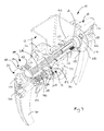
FIG. 3 is an exploded perspective view of a portion of the door latch assembly of FIG. 1;
FIG. 4 is an exploded perspective view of the latch mechanism of FIG. 1 coupled to a handle;
FIG. 5 is a cross sectional view of the door latch assembly taken along line 5-5 of FIG. 1;
FIG. 6 is a perspective view of the housing;
FIG. 7 is a bottom view of the housing of FIG. 6;
FIG. 8 is a perspective view of the retention pin; and
FIG. 9 is a perspective view of the latch assembly with portions of the latch assembly removed.
DETAILED DESCRIPTION
While the present disclosure may be susceptible to embodiment in different forms, there is shown in the drawings, and herein will be described in detail, embodiments with the understanding that the present description is to be considered an exemplification of the principles of the disclosure and is not intended to limit the disclosure to the details of construction and the arrangements of components set forth in the following description or illustrated in the drawings.
A door latch assembly 10 is shown coupled to a portion of an access door 12 and is used to secure door 12 in a closed position, as shown, for example, in FIG. 1. Door latch assembly 10 includes a pair of housings 14, 16 coupled to door 12 and a pair of handles 18, 20 that are pivotally coupled to housings 14, 16. Handles 18, 20 are identical in structure and each includes a pair of receivers 38 adapted to accept an indexible latch member 22 that is used to latch door 12 in a closed position, as shown, in the assembled view of FIG. 1 and in the exploded view of FIG. 4. The position of latch member 22 can be incrementally adjusted with respect to handles 18 or 20 to accommodate door frames of various thicknesses. Latch member 22 can also be positioned on either handle 18, 20 to permit the use of door latch assembly 10 on both inward and outward swing doors 12.
Door latch assembly 10 also includes a retention mechanism 24 that is comprised of a trigger 26 and a biased retention pin 28, as shown, for example, in FIGS. 3 and 9. Trigger 26 is slidably coupled to handle 18 and is adapted to engage and retract retention pin 28 when trigger 26 is depressed by a user. Retention pin 28 includes a pair of support posts 30 that are adapted to slide along a bearing surface 32 of housing 14. Housing 14 includes a retention zone 15 that holds handle 18 in an open horizontal position to prevent handle 18 from returning to the vertical position. Depressing trigger 26 causes the retraction of retention pin 28 from retention zone 15 to allow handle 18 to be rotated with respect to housing 14 to a closed position. Alternatively, a user can rotate handle 18 to a vertical position without depressing trigger 26.
Paragraph 20: Handle 18 of door latch assembly 10 includes a cylindrical body 34 and an elongated stem 36 extending from body 34, as shown, for example, in FIG. 2. Since handles 18 and 20 are identical in construction only one will be described in detail. Body 34 of handle 18 includes a receiver 38 for receiving latch member 22. Receiver 38 includes an annular recess 40 formed in body 34. Receiver 38 also includes an annular wall 42 positioned within recess 40 and is provided with a series of ribs 44 that extend from annular wall 42 to an inner surface 46 of annular recess 40 to form receptacles 48. Receptacles 48 are adapted to accept corresponding teeth 50 of latch member 22, as shown in FIG. 4. Annular wall 42 is threaded on an inner surface to accept a fastener 52 that is used to secure latch member 22 to body 34 of handle 18. Handle 18 also includes a second receiver 54 positioned on an opposite side of body 34 to allow latch member 22 to be coupled to either side of handle 18 so that handle 18 can be used on either side of door 12.
Latch member 22 is used to retain door 12 in a closed position and is adapted to be selectively coupled to either handle 18, 20 of door latch assembly 10 to accommodate both inward and outward swing doors, as shown, for example, in FIGS. 1 and 4. Latch member 22 includes a paw arm 56 and a latch roller 58. Paw arm 56 is shown in the illustrative embodiment as having a cylindrical base 60, a post 62 and a web 64 interconnecting post 62 to base 60. Base 60 of paw arm 56 includes the outwardly extending teeth 50 that are adapted to engage receptacles 48 formed in handles 18, 20. Base 60 of paw arm 56 also includes a central passageway 66 that is adapted to allow a portion of fastener 52 to extend therethrough. Base 60 further includes an annular recess 67 that is adapted to accept the head of fastener 52.
Teeth 50 of base 60 allow paw arm 56 to be repositioned in increments with respect to handle 18 to provide a range of adjustment to accommodate door frames of varying thicknesses. To reposition paw arm 56 with respect to handle 18, fastener 52 is unthreaded from handle 18 and paw arm 56 is removed from handle 18 and rotated until latch roller 58 is positioned against the door frame when door 12 is in a closed position. Once paw arm 56 is in the desired position, paw arm 56 is reinserted into receiver 38 of handle 18 and fastener 56 is reattached. Once paw arm 56 is adjusted for a given door/frame combination, it does not have to be repositioned again unless door latch assembly 10 is moved to a different door.
Latch roller 58 of latch member 22 is a cylindrical shaped structure having a central aperture 68 adapted to be positioned around post 62 of paw arm 56, as shown, for example, in FIG. 4. The diameter of aperture 68 is greater than the diameter of post 62 to allow latch roller 58 to rotate about post 62. Latch roller 58 is secured to post 62 by use of a retainer 70. Post 62 includes a recessed portion 71 that is adapted to accept retainer 70.
Housing 14 is positioned to lie near a leading edge 101 of door 12 and includes a bottom wall 72 and an annular side wall 74, as shown, for example, in FIGS. 1 and 6. Since housings 14, 16 are identical in construction, only one will be described in detail. Bottom wall 72 includes a first side surface 76 and a second side surface 78. First side surface 76 faces door 12 and includes a positioning stud 77 that is used to properly position housing 14 on door 12. Second side surface 78 includes a bearing surface 32 that is slidably engaged by support posts 30 of retention pin 28 when door latch assembly 10 is assembled.
The interaction of support posts 30 and bearing surface 32 creates friction to allow handle 18 to remain in a position selected by the user. Bottom wall 72 is also formed to include a central opening 80 that is adapted to accept half shaft 102 therethrough, as shown in FIG. 3. Annular side wall 74 of housing 14 is adapted to conceal bearing surface 32 and support posts 30 when door latch assembly 10 is assembled. An o-ring 77 is used between housing 14 and half shaft 102 to provide an air seal.
Paragraph 26: Bottom wall 72 is also provided with retention zone 15 that includes a plateau 82, as shown in FIGS. 3 and 6. Plateau 82 is positioned generally in the region of positioning stud 77 on the second side surface 78 of bottom wall 72. It is important when installing housing 14 that plateau 82 is properly oriented on door 12 to ensure that door latch assembly 10 operates as intended. Plateau 82 should be positioned toward the hinges of door 12. As an example, if housing 14 is installed on the inside surface of a inward swing door, plateau 82 would be pointed toward the axis of rotation of the door. If housing 14 is installed on the inside surface of an outward swing door, plateau 82 would still point toward the axis of rotation of the door.
Plateau 82 of retention zone 15 includes first and second detention apertures 84, 86 that are adapted to retain support posts 30 of retention pin 28 when handle 18 is rotated 90 degrees from the vertical or closed position, as shown, for example, in FIGS. 3 and 6. The bullet shape of support posts 30 and the diameter of detention apertures 84, 86 allows support posts 30 to be released from detention apertures 84, 86 when a clockwise rotation force is applied to handle 18. Positioned at the sides of plateau 82 are cam ramps 88, 90. Cam ramps 88, 90 are adapted to assist support posts 30 in transitioning from bearing surface 32 up to plateau 82.
Housing 14 also includes an annular sleeve 92 that extends outwardly from first side 76 of housing 14, as shown, for example, in FIGS. 3 and 6. Sleeve 92 is adapted to be inserted into a hole drilled in door 12 near leading edge 101 of door 12. Sleeve 92 includes an interior groove 98 that is adapted to engage an annular rib 100 formed on half shaft 102 to retain housing 14 to half shaft 102. Door latch assembly 10 also includes gasket 96 that is adapted to seal housing 14 to door 12.
Paragraph 29: Handles 18, 20 are coupled together by use of a pair of half shafts 102, 104 and a pair of handle bolts 128, 128′, as shown in FIGS. 3 and 5. Since half shafts 102, 104 are identical in construction only one will be described in detail. The interconnection of handles 18, 20 permits rotation of both handles at the same time, as shown, for example, in FIGS. 3 and 5. Thus, rotation of first handle 18 causes the rotation of second handle 20.
Half shaft 102 includes a flange 108 and a pair of arcuate fingers 110, 112 that extend outwardly from flange 108, as shown, for example, in FIG. 3. Flange 108 of half shaft 102 includes a first pair of apertures 114 that are adapted to accept posts 116 of handle 18 so that rotation of handle 18 causes rotation of shaft 102. Flange 108 also includes a second set of apertures 118 that are adapted to accept posts 30 of retention pin 28. Flange 108 is formed to include a recessed wall portion 120 that is adapted to slide along bearing surface 32 of housing 14 when handle 18 is rotated.
Fingers 110, 112 extend outwardly from flange 108 and have a curved outer surface 122 having annular rib 100, as shown in FIG. 3. Fingers 110, 112 also include a curved inner surface 124. Inner surfaces 124 of fingers 110, 112 include a plurality of threads 126 that are adapted to mesh with threads of handle bolt 128. Annular rib 100 is adapted to be coupled to sleeve 92 of housing 14 to secure housing 14 to door 12. Flange 108 includes a hexagonal ring 130 that is adapted to engage angular faces 132 of retention pin 28 to retain the orientation of retention pin 28 during lateral movement.
Retention mechanism 24 of door latch assembly 10 includes retention pin 28, trigger 26 and springs 148, 150, as shown, for example, in FIG. 3. Retention pin 28 includes a base member 138 and two upwardly extending columns 140, 142, as shown, for example, in FIG. 8. Columns 140, 142 each include an angular face 132 that is adapted to engage hexagonal ring 130 of half shaft 102 when door latch assembly 10 is assembled. Columns 140, 142 also include cylindrical projections 144, 146 that are adapted to engage springs 148, 150. Springs 148, 150 bias retention pin 28 away from handle 18 toward housing 14.
Base member 138 of retention pin 28 is formed to include an aperture 152 that is adapted to engage an actuator post 154 of trigger 26, as shown in FIGS. 3 and 9. Pulling trigger 26 toward stem 36 of handle 18 causes actuator post 154 to pull retention pin 28 toward handle 18 against the biasing force of springs 148, 150 to a release position. Release of trigger 26 allows springs 148, 150 to move retention pin 28 back to the engaged position. The use of spring loaded retention pin 28 and trigger 26 resists unintentional opening or closing of door 12.
Trigger 26 is coupled to handle 18 and is adapted to release retention pin 28 when pulled. Trigger 26 is positioned to lie within recess 156 of handle 18 and includes a leading wall 158 and a pair of backswept wall segments 160, 162, as shown, for example, in FIG. 3. Trigger 26 also includes an actuator post 154 that is adapted to engage retention pin 28. Trigger 26 further includes an outwardly extending stud 164 that is adapted to engage a lockout insert 166. Positioning lockout insert 166 in a lockout position prevents trigger 26 from moving toward handle 18. Rotating lockout insert 166 to a release position allows trigger 26 to move toward handle 18, which causes the retraction of retention pin 28 from housing 14.
Handle 18 includes an upper aperture 168 adapted to allow a portion of handle bolt 128 to pass through, as shown in FIG. 3. Upper aperture 168 is also adapted to accept a bolt cap 170 that is used to conceal handle bolt 128 after door latch assembly 10 is completely assembled. Handle 18 also includes a lower aperture 172 that is adapted to accept lockout insert 166. Stem 36 of handle 18 includes a series of linear grooves 174 that extend along the length of stem 36 to provide additional strength to stem 36 of handle 18.
Handle bolts 128, 128′ are used to couple first and second half shafts 102, 104, as shown, for example, in FIG. 5. A first handle bolt 128 passing through handle 18 engages threads formed on fingers 110, 112 of second half shaft 104 to couple handle 18, housing 14, first half shaft 102, and second half shaft 104 together. A second handle bolt 128′, passing through handle 20, engages threads of fingers of first half shaft 102 to couple handle 20, housing 16, second half shaft 104 and first half shaft 102 together. Thus, first handle 18 is coupled to second half shaft 104 by use of handle bolt 128 from one side of door 12 and second handle 20 is coupled to first half shaft 102 by use of a second handle bolt 128′ on the other side of door 12.
Door latch assembly 10 is thermally broke in that door latch assembly 10 has no exposed material capable of transmitting large amounts of heat through door 12 in either direction. In the preferred embodiment the only components of door latch assembly 10 that are metal, besides the springs, are flanges 102, 104 and bolts 128. The remaining components are preferably manufactured from a plastics material, which acts as an insulator, to limit the amount of heat transfer through door 12.
Door latch assembly 10 is versatile in that it works for both inward and outward swing doors using the same set of components, which saves costs and reduces complexity at a manufacturing level. Door latch assembly 10 can also be used for out-swing and in-swing doors without the need for additional components which reduces the number of door latch assembly kits that need to be manufactured to accommodate different doors.
In use, an installer first determines whether they have a left hand or right hand swing door. If the door is hinged on the right and the door swings inwardly, the installer drills a large hole and a small hole near free edge 101 of door 12. The smaller hole is located between the large hole and the hinges of the door along a line that is perpendicular to the axis of rotation of the hinges. Installation has been designed to be simple in that the installer only needs to locate and drill two properly sized holes through the door. Once the holes are drilled, the installer only needs a standard flat head screw driver to complete the installation.
Once the holes are drilled, the installer places gasket 96 and first housing 14 on the inside surface of the door so that annular sleeve 92 is positioned within the large hole and the positioning stud 77 is positioned in the small hole. In this position, plateau 82 and positioning stud 77 of first housing 14 are positioned between the large hole and the hinges of the door along a line that is perpendicular to the axis of rotation of the hinges, as shown, for example, in FIG. 3. Once the holes are drilled in door 12, the installer then inserts fingers 110, 112 of first half shaft 102 into opening 80 of housing 14 with recessed wall 120 of half shaft 102 positioned opposite of plateau 82 and resting against bearing surface 32.
With first half shaft 102 in position, the installer then positions handle 18, which has been pre-assembled with trigger 26, springs 148, 150, and retention pin 28, against flange 108 of first half shaft 102 with stem 36 of the handle 18 facing downwardly. In this position, posts 116 of handle 18 are positioned within apertures 114 and posts 30 of retention pin 28 are positioned within apertures 118 of first half shaft 102.
With the first handle 18 in position, the installer next positions second housing 16 on the second side of door 12, second half shaft 104 through housing 16, and couples second handle 20 to first half shaft 102 by use of second handle bolt 128′. The installer then couples the first handle bolt 128 to second half shaft 104. Once handles 18, are properly secured to door 12, the installer next installs indexible latch member 22. Since the installer is installing the door latch assembly 10 on a door that is hinged on the right and swings in the direction of first handle 18, the installer would install the indexible latch member 22 on the second door handle 20 on the receiver 38 closest to edge 101 of door 12.
To install indexible latch member 22, the installer inserts teeth 50 of paw arm 56 into receptacles 48 so that latch roller 58 engages the door frame when door 12 is in a closed position. Given the number of teeth 50, paw arm 56 can be indexed to accommodate door frames of varying thicknesses. Once the proper position of paw arm 56 with respect to second handle 20 is selected, fastener 52 is threaded into annular wall 42.
To open door 12 after door latch assembly 10 is installed, a user on the inside of the door rotates first handle 18 counterclockwise ninety degrees. During rotation of first handle 18, posts 30 of retention pin 28 slide across bearing surface 32 until one of the posts engages cam ramp 88. Cam ramp 88 forces posts 30 and retention pin 28 slightly rearwardly, toward handle 18 so that posts 30 can ramp up to plateau 82. Further rotation causes posts 30 of retention pin 28 to engage detention apertures 84, 86 which retain stem 36 of handle 18 in a horizontal plane. Posts 30 will remain on plateau 82 until the user forcibly rotates handle 18 in a clockwise direction to return handle 18 to a vertical position with stem 36 pointing downwardly.
Because first and second handles 18, 20 are interconnected by half shafts 102, 104 by use of handle bolts 128, rotation of first handle 18 causes rotation of second handle 20. Since indexible latch member 22 is coupled to second handle 20, rotation of second handle 20 also causes movement of indexible latch member 22 so that latch roller 58 clears the door frame to allow door 12 to open.
While embodiments have been illustrated and described in the drawings and foregoing description, such illustrations and descriptions are considered to be exemplary and not restrictive in character, it being understood that only illustrative embodiments have been shown and described and that all changes and modifications that come within the spirit of the disclosure are desired to be protected. The description and figures are intended as illustrations of embodiments of the disclosure, and are not intended to be construed as having or implying limitation of the disclosure to those embodiments.
There are a plurality of advantages of the present disclosure arising from various features set forth in the description. It will be noted that alternative embodiments of the disclosure may not include all of the features described yet still benefit from at least some of the advantages of such features. Those of ordinary skill in the art may readily devise their own implementations of the disclosure and associated methods, without undue experimentation, that incorporate one or more of the features of the disclosure and fall within the spirit and scope of the present disclosure and the appended claims.

Claims (8)

1. A latch assembly for use with a door that is hingedly coupled to a door frame, the latch assembly comprising:
(a) a first handle adapted to be pivotally coupled to a first side of the door;
(b) a second handle adapted to be pivotally coupled to a second side of the door opposite the first handle;
(c) an adjustable latch member that is selectively coupled to either of the first handle and the second handle and adapted to be selectively repositionable with respect to said selected one of the first handle and the second handle to allow for adjustment of the adjustable latch member with respect to the door frame; and
(d) a fastener;
wherein the adjustable latch member does not obstruct the opening of the door when the selected one of the first handle and the second handle is rotated to an open position, the adjustable latch member including a paw arm having a generally cylindrical shaped base including a series of teeth defining a plurality of receptacles, each of the first and second handles includes an annular wall defining a recess and a series of ribs disposed within the recess defining a plurality of receptacles and an opening concentric with the recess, the opening configured to receive the fastener for selectively coupling the adjustable latch member to the selected one of the first handle and the second handle; and
wherein, when the paw arm is engaged with the selected one of the first handle and the second handle at least some of the receptacles of the plurality of receptacles defined by the ribs of the selected one of the first handle and the second handle receive the teeth of the paw arm and the ribs of the selected one of the first and the second handle are received by at least some of the receptacles of the plurality of receptacles defined by the paw arm.
2. The latch assembly of claim 1, wherein the adjustable latch member includes a latch roller that is adapted to engage the door frame.
3. The latch assembly of claim 1, wherein the teeth of the paw arm are also adapted to be selectively coupled to other receptacles of the plurality of receptacles defined by the selected one of the first handle and the second handle.
4. The latch assembly of claim 3, wherein the latch roller is coupled to the paw arm.
5. latch assembly of claim 1, wherein the handles are manufactured from a thermally insulative material to limit the amount of heat loss through the door.
6. The latch assembly of claim 1 wherein the adjustable latch member is readily removable from said selected one of the first handle and the second handle when the first and second handles are coupled to the door.
7. The latch assembly of claim 6, wherein the adjustable latch member includes a latch roller that is adapted to engage the door frame.
8. The latch assembly of claim 6, wherein the teeth of the paw arm are also adapted to be selectively coupled to other receptacles of the plurality of receptacles defined by the selected one of the first handle and the second handle and to be readily removed from said other receptacles when the first and second handles are coupled to the door.
US11/942,509 2007-11-19 2007-11-19 Door latch assembly Expired - Fee Related US7819443B2 (en)

Priority Applications (1)

Application Number Priority Date Filing Date Title
US11/942,509 US7819443B2 (en) 2007-11-19 2007-11-19 Door latch assembly

Applications Claiming Priority (1)

Application Number Priority Date Filing Date Title
US11/942,509 US7819443B2 (en) 2007-11-19 2007-11-19 Door latch assembly

Publications (2)

Publication Number Publication Date
US20090127874A1 US20090127874A1 (en) 2009-05-21
US7819443B2 true US7819443B2 (en) 2010-10-26

Family

ID=40641114

Family Applications (1)

Application Number Title Priority Date Filing Date
US11/942,509 Expired - Fee Related US7819443B2 (en) 2007-11-19 2007-11-19 Door latch assembly

Country Status (1)

Country Link
US (1) US7819443B2 (en)

Cited By (13)

* Cited by examiner, † Cited by third party
Publication number Priority date Publication date Assignee Title
US20110278865A1 (en) * 2010-05-17 2011-11-17 Ryan Jr Gerald G Door Latch
US20150107314A1 (en) * 2013-10-21 2015-04-23 S.P.E.P. Acquisition Corp. Defeater Latch Handle
US9267310B2 (en) * 2010-12-20 2016-02-23 Industrilås i NässjöAB Handle assembly for double-walled door
US20170175424A1 (en) * 2015-12-22 2017-06-22 Leviton Manufacturing Co., Inc. Locking and sealing arrangement for a load switch handle
USD793838S1 (en) * 2016-03-25 2017-08-08 S.P.E.P. Acquisition Corp. Defeater latch handle with trigger and escutcheon
USD794411S1 (en) * 2016-03-25 2017-08-15 S.P.E.P. Acquisition Corp. Defeater latch handle with escutcheon
US10916386B2 (en) * 2011-11-15 2021-02-09 Rockwell Automation Technologies, Inc. Handle assembly with defeater and related methods
USD923450S1 (en) * 2019-09-30 2021-06-29 Shenzhen Leqi Network Technology Co., Ltd. Handle
US11261628B2 (en) * 2017-02-08 2022-03-01 Kason Industries, Inc. Cold room latch
USD950353S1 (en) * 2021-06-29 2022-05-03 Safesky Technology Co., Ltd. Fingerprint door lock
USD965410S1 (en) * 2021-07-09 2022-10-04 Jiangmen Pengjiang MTT Gloria Trading Co., Ltd. Fingerprint lock
US11542723B2 (en) 2018-09-19 2023-01-03 Johnson Controls Tyco IP Holdings LLP Convertible access panel latch assembly
USD1011864S1 (en) 2022-04-15 2024-01-23 S.P.E.P. Acquisition Corp. Trigger for compact defeater handle

Families Citing this family (2)

* Cited by examiner, † Cited by third party
Publication number Priority date Publication date Assignee Title
CN203482529U (en) * 2013-07-29 2014-03-12 中兴通讯股份有限公司 Device for locking seal interface of maintenance window
PL3354824T3 (en) * 2017-01-27 2021-08-30 Emka Beschlagteile Gmbh & Co. Kg Roller tongue

Citations (55)

* Cited by examiner, † Cited by third party
Publication number Priority date Publication date Assignee Title
US947641A (en) * 1908-12-10 1910-01-25 Frank Lahr Double-door lock.
US1812334A (en) 1930-07-10 1931-06-30 Gloekler John Edward Latch construction
US2160611A (en) 1936-12-03 1939-05-30 Grover C Alexander Automobile door handle
US2219626A (en) * 1939-12-27 1940-10-29 John W Johnson Motor vehicle door handle
US2473937A (en) 1947-05-20 1949-06-21 Edward H Cameron Safety automobile door lock handle
US2701735A (en) 1951-03-26 1955-02-08 Segal Samuel Doorknob attaching device
US2707121A (en) 1952-03-14 1955-04-26 Yale & Towne Mfg Co Screen door latch
US2851871A (en) 1957-01-11 1958-09-16 Newell Mfg Company Door latch
US2949328A (en) 1957-11-07 1960-08-16 Kaiser Fred Door lock set
US3159994A (en) 1962-03-01 1964-12-08 S B Mfg Company Door latch and lock
US3808850A (en) * 1972-03-02 1974-05-07 Bmr Security Prod Corp Locking handle assembly
US4471984A (en) * 1983-03-31 1984-09-18 Emhart Industries, Inc. Lever handle assembly
US4583775A (en) 1984-05-16 1986-04-22 Southco, Inc. Latch assembly having pull-up action
US4732418A (en) 1983-09-19 1988-03-22 National Manufacturing Knob latch
US4763935A (en) 1987-03-25 1988-08-16 Southco, Inc. Door or panel fastener
US5172944A (en) 1991-11-27 1992-12-22 Federal-Hoffman, Inc. Multiple point cam-pinion door latch
US5184853A (en) 1992-07-01 1993-02-09 Northern Telecom Limited Tool operable door lock mechanism
USD343347S (en) 1992-08-04 1994-01-18 Federal-Hoffman, Inc. Low-profile enclosure handle
US5292189A (en) 1991-11-27 1994-03-08 Federal-Hoffman, Inc. Sub-panel guide system for electrical enclosure
US5299597A (en) 1990-08-31 1994-04-05 Fort Vale Engineering Limited Valve operating handle
US5390517A (en) * 1993-03-04 1995-02-21 Takigen Manufacturing Co. Ltd. Door lock handle assembly
US5408853A (en) * 1993-03-02 1995-04-25 Takigen Manufacturing Co. Ltd. Door locking handle assembly
USD360345S (en) 1994-01-26 1995-07-18 Federal-Hoffman, Inc. Combined handle and lock unit
US5469725A (en) 1993-03-16 1995-11-28 Takigen Manufacturing Co., Ltd. Door locking handle assembly of pull-out and side-swinging lever-action type
US5481889A (en) 1993-01-15 1996-01-09 Federal-Hoffman, Inc. Mechanical latch system
US5505505A (en) * 1994-05-10 1996-04-09 Vanguard Plastics (1971) Ltd. Device for securing a closure such as a window
US5509703A (en) 1994-01-21 1996-04-23 Federal-Hoffman, Inc. Enclosure latch
US5520427A (en) 1993-12-27 1996-05-28 Von Duprin, Inc. Breakaway lever with wedge release mechanism
USD371300S (en) 1995-03-03 1996-07-02 Federal-Hoffman, Inc. Safety double lock
US5582042A (en) 1995-03-03 1996-12-10 Federal-Hoffman, Inc. Safety double lock
US5582443A (en) 1995-03-27 1996-12-10 Finkelstein; Burl Locking assembly for refrigerator doors
US5620290A (en) 1995-08-23 1997-04-15 Illinois Tool Works Inc. Ground retainer
US5630632A (en) 1994-12-07 1997-05-20 Federal-Hoffman, Inc. Quarter turn latch
US5634357A (en) 1995-03-03 1997-06-03 Federal-Hoffman, Inc. Enclosure handle
US5642909A (en) 1996-03-01 1997-07-01 Federal-Hoffman, Inc. Latch system
US5664448A (en) 1994-02-01 1997-09-09 Federal-Hoffman, Inc. Locking door handle
US5666695A (en) 1993-11-19 1997-09-16 Federal-Hoffman, Inc. Hinge system
USD385768S (en) 1995-03-03 1997-11-04 Federal-Hoffman, Inc. Handle
US5683005A (en) 1996-02-27 1997-11-04 Federal-Hoffman, Inc. Adjustable mounting system
US5704100A (en) 1996-03-01 1998-01-06 Federal-Hoffman, Inc. Retaining clip system
USD391143S (en) 1996-10-04 1998-02-24 Federal-Hoffman, Inc. Low profile handle
US5722121A (en) 1996-02-27 1998-03-03 Federal-Hoffman, Inc. Enclosure hinge
USD396397S (en) 1996-03-19 1998-07-28 Hoffman Enclosures Inc. Latch apparatus
USD400076S (en) 1997-01-22 1998-10-27 Hoffman Enclosures, Inc. Cabinet latch
US5862690A (en) 1996-10-04 1999-01-26 Hoffman Enclosures, Inc. Low profile handle
US5879035A (en) 1997-01-22 1999-03-09 Hoffman Enclosures, Inc. Cabinet latch
USD411433S (en) 1996-03-01 1999-06-22 Hoffman Enclosures, Inc. Enclosure handle
US6068308A (en) * 1998-03-13 2000-05-30 Austin Hardware, Inc. Latch assembly
US6086308A (en) 1997-08-13 2000-07-11 Quipp Systems, Inc. Cart handling system
US6101856A (en) 1998-12-14 2000-08-15 Sargent Manufacturing Company Free-wheeling lever handle lock mechanism
US6354119B1 (en) * 1999-11-24 2002-03-12 Austin Hardware, Inc. Handle and lock
US6474119B1 (en) 1999-01-28 2002-11-05 Fastec Industrial Corp. Pop-up handle assembly
US6502872B1 (en) * 1998-10-09 2003-01-07 Austin Hardware, Inc. Latch assembly
US6874825B1 (en) * 2004-03-08 2005-04-05 Paula M. Rauner Drawer locking assembly
US6952940B2 (en) * 2000-10-23 2005-10-11 Allegis Corporation Double lock T-handle assembly

Patent Citations (61)

* Cited by examiner, † Cited by third party
Publication number Priority date Publication date Assignee Title
US947641A (en) * 1908-12-10 1910-01-25 Frank Lahr Double-door lock.
US1812334A (en) 1930-07-10 1931-06-30 Gloekler John Edward Latch construction
US2160611A (en) 1936-12-03 1939-05-30 Grover C Alexander Automobile door handle
US2219626A (en) * 1939-12-27 1940-10-29 John W Johnson Motor vehicle door handle
US2473937A (en) 1947-05-20 1949-06-21 Edward H Cameron Safety automobile door lock handle
US2701735A (en) 1951-03-26 1955-02-08 Segal Samuel Doorknob attaching device
US2707121A (en) 1952-03-14 1955-04-26 Yale & Towne Mfg Co Screen door latch
US2851871A (en) 1957-01-11 1958-09-16 Newell Mfg Company Door latch
US2949328A (en) 1957-11-07 1960-08-16 Kaiser Fred Door lock set
US3159994A (en) 1962-03-01 1964-12-08 S B Mfg Company Door latch and lock
US3808850A (en) * 1972-03-02 1974-05-07 Bmr Security Prod Corp Locking handle assembly
US4471984A (en) * 1983-03-31 1984-09-18 Emhart Industries, Inc. Lever handle assembly
US4732418A (en) 1983-09-19 1988-03-22 National Manufacturing Knob latch
US4583775A (en) 1984-05-16 1986-04-22 Southco, Inc. Latch assembly having pull-up action
US4763935A (en) 1987-03-25 1988-08-16 Southco, Inc. Door or panel fastener
US5299597A (en) 1990-08-31 1994-04-05 Fort Vale Engineering Limited Valve operating handle
US5172944A (en) 1991-11-27 1992-12-22 Federal-Hoffman, Inc. Multiple point cam-pinion door latch
US5292189A (en) 1991-11-27 1994-03-08 Federal-Hoffman, Inc. Sub-panel guide system for electrical enclosure
US5184853A (en) 1992-07-01 1993-02-09 Northern Telecom Limited Tool operable door lock mechanism
USD343347S (en) 1992-08-04 1994-01-18 Federal-Hoffman, Inc. Low-profile enclosure handle
US5481889A (en) 1993-01-15 1996-01-09 Federal-Hoffman, Inc. Mechanical latch system
US5408853A (en) * 1993-03-02 1995-04-25 Takigen Manufacturing Co. Ltd. Door locking handle assembly
US5390517A (en) * 1993-03-04 1995-02-21 Takigen Manufacturing Co. Ltd. Door lock handle assembly
US5469725A (en) 1993-03-16 1995-11-28 Takigen Manufacturing Co., Ltd. Door locking handle assembly of pull-out and side-swinging lever-action type
US5666695A (en) 1993-11-19 1997-09-16 Federal-Hoffman, Inc. Hinge system
US5520427A (en) 1993-12-27 1996-05-28 Von Duprin, Inc. Breakaway lever with wedge release mechanism
US5509703A (en) 1994-01-21 1996-04-23 Federal-Hoffman, Inc. Enclosure latch
USD360345S (en) 1994-01-26 1995-07-18 Federal-Hoffman, Inc. Combined handle and lock unit
US5664448A (en) 1994-02-01 1997-09-09 Federal-Hoffman, Inc. Locking door handle
US5505505A (en) * 1994-05-10 1996-04-09 Vanguard Plastics (1971) Ltd. Device for securing a closure such as a window
US5630632A (en) 1994-12-07 1997-05-20 Federal-Hoffman, Inc. Quarter turn latch
USD371300S (en) 1995-03-03 1996-07-02 Federal-Hoffman, Inc. Safety double lock
US5582042A (en) 1995-03-03 1996-12-10 Federal-Hoffman, Inc. Safety double lock
USD385768S (en) 1995-03-03 1997-11-04 Federal-Hoffman, Inc. Handle
US5634357A (en) 1995-03-03 1997-06-03 Federal-Hoffman, Inc. Enclosure handle
US5582443A (en) 1995-03-27 1996-12-10 Finkelstein; Burl Locking assembly for refrigerator doors
US5620290A (en) 1995-08-23 1997-04-15 Illinois Tool Works Inc. Ground retainer
US5683005A (en) 1996-02-27 1997-11-04 Federal-Hoffman, Inc. Adjustable mounting system
US5722121A (en) 1996-02-27 1998-03-03 Federal-Hoffman, Inc. Enclosure hinge
US5642909A (en) 1996-03-01 1997-07-01 Federal-Hoffman, Inc. Latch system
US5704100A (en) 1996-03-01 1998-01-06 Federal-Hoffman, Inc. Retaining clip system
USD411433S (en) 1996-03-01 1999-06-22 Hoffman Enclosures, Inc. Enclosure handle
USD396397S (en) 1996-03-19 1998-07-28 Hoffman Enclosures Inc. Latch apparatus
USD391143S (en) 1996-10-04 1998-02-24 Federal-Hoffman, Inc. Low profile handle
US5862690A (en) 1996-10-04 1999-01-26 Hoffman Enclosures, Inc. Low profile handle
USD400076S (en) 1997-01-22 1998-10-27 Hoffman Enclosures, Inc. Cabinet latch
US5879035A (en) 1997-01-22 1999-03-09 Hoffman Enclosures, Inc. Cabinet latch
US6086308A (en) 1997-08-13 2000-07-11 Quipp Systems, Inc. Cart handling system
US6494509B2 (en) * 1998-03-13 2002-12-17 Austin Hardware, Inc. Latch assembly
US6715807B2 (en) * 1998-03-13 2004-04-06 Austin Hardware, Inc. Latch assembly
US6318770B1 (en) * 1998-03-13 2001-11-20 Austin Hardware, Inc. Latch assembly
US6068308A (en) * 1998-03-13 2000-05-30 Austin Hardware, Inc. Latch assembly
US6502872B1 (en) * 1998-10-09 2003-01-07 Austin Hardware, Inc. Latch assembly
US6702342B2 (en) * 1998-10-09 2004-03-09 Austin Hardware, Inc. Latch assembly
US6101856A (en) 1998-12-14 2000-08-15 Sargent Manufacturing Company Free-wheeling lever handle lock mechanism
US6474119B1 (en) 1999-01-28 2002-11-05 Fastec Industrial Corp. Pop-up handle assembly
US6354119B1 (en) * 1999-11-24 2002-03-12 Austin Hardware, Inc. Handle and lock
US6662605B2 (en) * 1999-11-24 2003-12-16 Austin Hardware, Inc. Handle and lock
US6868703B2 (en) * 1999-11-24 2005-03-22 Austin Hardware, Inc. Handle and lock
US6952940B2 (en) * 2000-10-23 2005-10-11 Allegis Corporation Double lock T-handle assembly
US6874825B1 (en) * 2004-03-08 2005-04-05 Paula M. Rauner Drawer locking assembly

Cited By (15)

* Cited by examiner, † Cited by third party
Publication number Priority date Publication date Assignee Title
US20110278865A1 (en) * 2010-05-17 2011-11-17 Ryan Jr Gerald G Door Latch
US9267310B2 (en) * 2010-12-20 2016-02-23 Industrilås i NässjöAB Handle assembly for double-walled door
US10916386B2 (en) * 2011-11-15 2021-02-09 Rockwell Automation Technologies, Inc. Handle assembly with defeater and related methods
US20150107314A1 (en) * 2013-10-21 2015-04-23 S.P.E.P. Acquisition Corp. Defeater Latch Handle
US9080347B2 (en) * 2013-10-21 2015-07-14 S.P.E.P. Acquisition Corp. Defeater latch handle
US9828789B2 (en) * 2015-12-22 2017-11-28 Leviton Manufacturing Co., Inc. Locking and sealing arrangement for a load switch handle
US20170175424A1 (en) * 2015-12-22 2017-06-22 Leviton Manufacturing Co., Inc. Locking and sealing arrangement for a load switch handle
USD794411S1 (en) * 2016-03-25 2017-08-15 S.P.E.P. Acquisition Corp. Defeater latch handle with escutcheon
USD793838S1 (en) * 2016-03-25 2017-08-08 S.P.E.P. Acquisition Corp. Defeater latch handle with trigger and escutcheon
US11261628B2 (en) * 2017-02-08 2022-03-01 Kason Industries, Inc. Cold room latch
US11542723B2 (en) 2018-09-19 2023-01-03 Johnson Controls Tyco IP Holdings LLP Convertible access panel latch assembly
USD923450S1 (en) * 2019-09-30 2021-06-29 Shenzhen Leqi Network Technology Co., Ltd. Handle
USD950353S1 (en) * 2021-06-29 2022-05-03 Safesky Technology Co., Ltd. Fingerprint door lock
USD965410S1 (en) * 2021-07-09 2022-10-04 Jiangmen Pengjiang MTT Gloria Trading Co., Ltd. Fingerprint lock
USD1011864S1 (en) 2022-04-15 2024-01-23 S.P.E.P. Acquisition Corp. Trigger for compact defeater handle

Also Published As

Publication number Publication date
US20090127874A1 (en) 2009-05-21

Similar Documents

Publication Publication Date Title
US7819443B2 (en) Door latch assembly
JP5020148B2 (en) Sliding door double lock
US9737174B2 (en) Track corner connecting device for shower door, shower door frame and shower door
US20180044974A1 (en) Molded plastic access door
US7814621B1 (en) Stay-closed hinge
US7926315B2 (en) Lock assembly with anti-panic feature and associated method
US4055360A (en) Security lock
US20060202491A1 (en) Operating mechanism
US6684570B1 (en) Door lock system
KR102042596B1 (en) Door lock for fire doors
US20120124776A1 (en) Adjustable door stop with hinge pin
TWI710694B (en) Adjustable backset cylindrical latch
US4288120A (en) Door latch assembly
US20100187839A1 (en) Handle assembly
HUE028297T2 (en) Smoke evacuation shutter
US20120286527A1 (en) Adjustable strike plate
US20190301204A1 (en) Barn door handle assembly, strike assembly, and lock system
US9476222B1 (en) Latch blocker safety strike plate
US7152891B2 (en) Field-reversible locking mechanism
WO2009141602A2 (en) Improvements to door latch assemblies
GB2546327A (en) Security cowl and fixing
CA3037517A1 (en) Vent cover
US20040205936A1 (en) Escutcheon plate assembly
US7828347B2 (en) Fire plate for a bored in lock assembly
KR101941589B1 (en) Lever typed handle for direct locking system

Legal Events

Date Code Title Description
AS Assignment

Owner name: VENTFABRICS, INC., ILLINOIS

Free format text: ASSIGNMENT OF ASSIGNORS INTEREST;ASSIGNOR:RYAN, JERRY;REEL/FRAME:020137/0785

Effective date: 20071031

FPAY Fee payment

Year of fee payment: 4

FEPP Fee payment procedure

Free format text: MAINTENANCE FEE REMINDER MAILED (ORIGINAL EVENT CODE: REM.)

LAPS Lapse for failure to pay maintenance fees

Free format text: PATENT EXPIRED FOR FAILURE TO PAY MAINTENANCE FEES (ORIGINAL EVENT CODE: EXP.); ENTITY STATUS OF PATENT OWNER: SMALL ENTITY

STCH Information on status: patent discontinuation

Free format text: PATENT EXPIRED DUE TO NONPAYMENT OF MAINTENANCE FEES UNDER 37 CFR 1.362

FP Lapsed due to failure to pay maintenance fee

Effective date: 20181026