US7802379B2 - Article of footwear with indented tip cleats - Google Patents

Article of footwear with indented tip cleats Download PDF

Info

Publication number
US7802379B2
US7802379B2 US11/683,967 US68396707A US7802379B2 US 7802379 B2 US7802379 B2 US 7802379B2 US 68396707 A US68396707 A US 68396707A US 7802379 B2 US7802379 B2 US 7802379B2
Authority
US
United States
Prior art keywords
cleats
cleat
outsole
article
diameter
Prior art date
Legal status (The legal status is an assumption and is not a legal conclusion. Google has not performed a legal analysis and makes no representation as to the accuracy of the status listed.)
Active, expires
Application number
US11/683,967
Other versions
US20080216362A1 (en
Inventor
Clifford B. Gerber
Current Assignee (The listed assignees may be inaccurate. Google has not performed a legal analysis and makes no representation or warranty as to the accuracy of the list.)
Nike Inc
Original Assignee
Nike Inc
Priority date (The priority date is an assumption and is not a legal conclusion. Google has not performed a legal analysis and makes no representation as to the accuracy of the date listed.)
Filing date
Publication date
Application filed by Nike Inc filed Critical Nike Inc
Priority to US11/683,967 priority Critical patent/US7802379B2/en
Assigned to NIKE, INC. reassignment NIKE, INC. ASSIGNMENT OF ASSIGNORS INTEREST (SEE DOCUMENT FOR DETAILS). Assignors: GERBER, CLIFFORD B.
Publication of US20080216362A1 publication Critical patent/US20080216362A1/en
Application granted granted Critical
Publication of US7802379B2 publication Critical patent/US7802379B2/en
Active legal-status Critical Current
Adjusted expiration legal-status Critical

Links

Images

Classifications

    • AHUMAN NECESSITIES
    • A43FOOTWEAR
    • A43BCHARACTERISTIC FEATURES OF FOOTWEAR; PARTS OF FOOTWEAR
    • A43B13/00Soles; Sole-and-heel integral units
    • A43B13/14Soles; Sole-and-heel integral units characterised by the constructive form
    • A43B13/141Soles; Sole-and-heel integral units characterised by the constructive form with a part of the sole being flexible, e.g. permitting articulation or torsion
    • AHUMAN NECESSITIES
    • A43FOOTWEAR
    • A43BCHARACTERISTIC FEATURES OF FOOTWEAR; PARTS OF FOOTWEAR
    • A43B13/00Soles; Sole-and-heel integral units
    • A43B13/02Soles; Sole-and-heel integral units characterised by the material
    • A43B13/026Composites, e.g. carbon fibre or aramid fibre; the sole, one or more sole layers or sole part being made of a composite
    • AHUMAN NECESSITIES
    • A43FOOTWEAR
    • A43BCHARACTERISTIC FEATURES OF FOOTWEAR; PARTS OF FOOTWEAR
    • A43B5/00Footwear for sporting purposes
    • A43B5/02Football boots or shoes, i.e. for soccer, football or rugby
    • AHUMAN NECESSITIES
    • A43FOOTWEAR
    • A43CFASTENINGS OR ATTACHMENTS OF FOOTWEAR; LACES IN GENERAL
    • A43C15/00Non-skid devices or attachments
    • A43C15/16Studs or cleats for football or like boots
    • A43C15/161Studs or cleats for football or like boots characterised by the attachment to the sole

Definitions

  • the present invention relates generally to articles of footwear and in particular to footwear with multiple cleat sizes.
  • Minihane (U.S. Pat. No. 3,988,840) also teaches a shoe where more than one type of cleat is provided.
  • Minihane teaches a structure having cleats of two different types including uniformly spaced frustoconical cleats in the ball and heel areas and spaced peripheral cleats at the edges of the sole.
  • the peripheral cleats are generally shorter than the frustoconical cleats.
  • the prior art teaches articles of footwear including multiple cleat sizes, the prior art does not teach different sized cleats disposed along the lateral and medial sides. Additionally, the prior art teaches generally flat cleats that conform to a planar surface. The prior art does not teach cleats that are contoured to a curved surface in the forefoot area. Furthermore the prior art does not teach cleats including indented cleat tips.
  • an article of footwear with multiple sized cleats is disclosed.
  • the invention provides an article of footwear including an outsole, comprising: a first cleat disposed along an outer surface of the outsole; the first cleat including a first tip portion; and where the first tip portion includes a first indentation.
  • the first indentation is spherical.
  • the outsole includes a second cleat with a second indentation.
  • the first indentation has a first size and the second indentation has a second size.
  • the first size is larger than the second size.
  • the outsole includes more than two cleats.
  • the invention provides an article of footwear including an outsole, comprising: at least one cleat disposed along an outer surface of the outsole; the cleat including a tip portion; the tip portion including an outer periphery and a central portion; and where the central portion is indented and the outer periphery is rounded.
  • the outer periphery of the tip portion is flat.
  • the central portion is spherically indented.
  • the outsole includes multiple cleats.
  • the multiple cleats are associated with multiple indentations.
  • the multiple indentations are spherical.
  • the at least one cleat is disposed along a first portion of the outer surface of the outsole.
  • the invention provides an article of footwear including an outsole, comprising; at least one cleat disposed along an outer surface of the outsole; the cleat including a tip portion; the tip portion including an outer periphery and a central portion; and where the central portion is indented and the outer periphery is flat.
  • the outer periphery is rounded.
  • the central portion is spherically indented.
  • the outsole includes multiple cleats.
  • the multiple cleats are associated with multiple indentations.
  • the multiple indentations are spherical.
  • the at least one cleat is disposed along a first portion of the outer surface of the outsole.
  • the invention provides an article of footwear including an outsole, comprising: a first cleat and a second cleat disposed along an outer surface of the outsole; the first cleat including a first tip portion and the second cleat including a second tip portion; the first tip portion including a first indentation and the second tip portion including a second indentation; and where the first indentation is larger than the second indentation.
  • the outer surface of the outsole is curved along a first portion of the outsole.
  • the first indentation is spherically indented.
  • the second indentation is spherically indented.
  • first cleat is disposed along the first portion of the outsole and the second cleat is disposed along a third portion of the outsole.
  • the first portion is a forefoot portion.
  • the third portion is a heel portion.
  • FIG. 1 is a plan view of a preferred embodiment of an outsole with a cleat system
  • FIG. 2 is a side view of a preferred embodiment of an outsole with a cleat system
  • FIG. 3 is a cross sectional view of a preferred embodiment of an outsole with a cleat system
  • FIG. 4 is an isometric view of a preferred embodiment of an outsole with a cleat system
  • FIG. 5 is an isometric view of a preferred embodiment of an outsole with a cleat system
  • FIG. 6 is an isometric view of a preferred embodiment of a cleat
  • FIG. 7 is a cross sectional view of a preferred embodiment of a cleat
  • FIG. 8 is a plan view of a preferred embodiment of a ring of contact between a cleat and a planar surface
  • FIG. 9 is an isometric view of a preferred embodiment of a cleat
  • FIG. 10 is a plan view of a preferred embodiment of a ring of contact between a cleat and a planar surface
  • FIG. 11 is a cross sectional view of a preferred embodiment of a cleat
  • FIG. 12 is a cross sectional view of a preferred embodiment of a cleat
  • FIG. 13 is a cross sectional view of a preferred embodiment of a cleat
  • FIG. 14 is a cross sectional view of a preferred embodiment of a cleat
  • FIG. 15 is an isometric view of a preferred embodiment of an outsole with a cleat system.
  • FIG. 16 is an exploded isometric view of a preferred embodiment of an outsole with an internal structural plate.
  • FIG. 1 is a plan view of a preferred embodiment of outsole 100 in the form of a football cleat outsole.
  • outsole 100 in the form of a football cleat outsole.
  • the present invention could also take the form of any other kind of footwear outsole, including for example, a baseball cleat outsole, a soccer cleat outsole, or any other kind of footwear outsole that includes cleats.
  • outsole 100 may be constructed of a lightweight and flexible material. In some embodiments, outsole 100 may be constructed of a plastic material. In a preferred embodiment, outsole 100 may be constructed of a plastic molding, such as Pebax® or other thermoplastic elastomers, thermoplastic polyurethane (TPU), or carbon fiber.
  • a plastic molding such as Pebax® or other thermoplastic elastomers, thermoplastic polyurethane (TPU), or carbon fiber.
  • Outsole 100 preferably includes first portion 102 , second portion 104 and third portion 106 .
  • first portion 102 may be a forefoot portion.
  • second portion 104 may be an arch portion.
  • third portion 106 may be a heel portion.
  • outsole 100 may be divided into a different number of portions other than three.
  • outsole 100 includes provisions for providing traction between the ground and bottom surface 108 of outsole 100 .
  • outsole 100 may be associated with cleats.
  • cleats may be configured to penetrate or interact with the ground, providing the user with a preconfigured amount of traction.
  • outsole 100 may be associated with cleat system 110 .
  • Cleat system 110 preferably includes cleats 111 - 131 .
  • cleats 111 - 131 may be constructed of similar materials.
  • the types of materials that may be used to construct cleats 111 - 131 include, but are not limited to plastic, metal, rubber, as well as other types of materials.
  • cleats 111 - 131 may be constructed of a hard molded plastic.
  • cleat system 110 may be divided into multiple groups of cleats, with each cleat group sharing common characteristics such as cleat size.
  • cleat system 110 preferably includes first cleat group 141 .
  • first cleat group 141 including cleats 111 - 117 , may be disposed along outer periphery 140 of first portion 102 .
  • first cleat group 141 may be disposed along both medial side 150 and front side 151 of outsole 100 .
  • first cleat group 141 includes seven cleats. In other embodiments, however, the number of cleats comprising first cleat group 141 may vary.
  • cleat system 110 may also include second cleat group 142 .
  • Second cleat group 142 including cleats 118 - 121 , may also be disposed along outer periphery 140 of first portion 102 .
  • second cleat group 142 is disposed along a different portion of outer periphery 140 than first cleat group 141 .
  • second cleat group 142 may be disposed along lateral side 152 of outsole 100 .
  • second cleat group 142 includes four cleats. In other embodiments, however, the number of cleats comprising second cleat group 142 may vary.
  • cleat system 110 may include third cleat group 143 .
  • third cleat group 143 which includes cleats 122 - 125 , may be disposed along third portion 106 of outsole 100 .
  • cleats 122 and 123 may be disposed along lateral side 152 of outsole 100
  • cleats 124 and 125 may be disposed along medial side 150 of outsole 100 .
  • third cleat group 143 includes four cleats.
  • the number of cleats comprising third cleat group 143 may vary.
  • cleat system 110 may also include fourth cleat group 144 .
  • fourth cleat group 144 which includes cleats 126 - 131 , may be disposed within inner portion 160 of first portion 102 .
  • Inner portion 160 is preferably a portion of outsole 100 that is disposed within outer periphery 140 .
  • fourth cleat group 144 preferably includes six cleats. However, in some embodiments, the number of cleats comprising fourth cleat group 144 may vary.
  • cleat system 110 includes provisions for providing different types of traction and support along different regions of outsole 100 .
  • these provisions may include using different sized cleats.
  • each of the cleat groups 141 - 144 may include cleats that are a different size that the cleats of the other cleat groups.
  • first cleat 111 of first cleat group 141 may have a first diameter D 1 .
  • the remaining cleats 112 - 117 of first cleat group 141 are constructed in a substantially similar manner to first cleat 111 , and therefore cleats 112 - 117 may also have widths substantially similar to first diameter D 1 .
  • second cleat 118 of second cleat group 142 may have a second diameter D 2 .
  • the remaining cleats 119 - 121 of second cleat group 142 are constructed in a substantially similar manner to second cleat 118 , and therefore cleats 119 - 121 may also have widths substantially similar to second diameter D 2 .
  • first diameter D 1 may be smaller than second diameter D 2 .
  • the cleats of first cleat group 141 may have a smaller width, or diameter, than the cleats of second cleat group 142 .
  • outer periphery 140 can include cleats having different sizes.
  • second cleat group 142 may provide more support to lateral side 152 of outsole 100 because of the larger diameter D 2 associated with second cleat group 142 . This may decrease the tendency of forefoot portion 102 to roll outwards and may decrease injuries to a user's foot.
  • first cleat group 141 may be associated with smaller diameter D 1 , first cleat group 141 may penetrate more quickly into a surface than second cleat group 142 . This fast penetration allows for rapid changes in the direction of movement of the athlete. Also, in this manner, first cleat group 141 may provide forefoot portion 102 with additional traction along medial side 150 of outsole 100 .
  • third cleat 122 of third cleat group 143 may have a third diameter D 3 .
  • the remaining cleats 123 - 125 of third cleat group 143 are constructed to be substantially similar to third cleat 122 , and therefore cleats 123 - 125 may have widths substantially similar to third diameter D 3 .
  • third diameter D 3 may be larger than first diameter D 1 and second diameter D 2 .
  • third diameter D 3 is the largest diameter associated with any of the cleat groups.
  • third cleat group 143 preferably penetrates into a surface less than the remaining cleat groups. This provision preferably gives the user some traction along the heel, but prevents the user's heel from sinking too deep into a surface.
  • fourth cleat 126 of fourth cleat group 144 may have a fourth diameter D 4 .
  • the remaining cleats 127 - 131 of fourth cleat group 144 are constructed to be substantially similar to fourth cleat 126 , and therefore cleats 127 - 131 may have widths substantially similar to fourth diameter D 4 .
  • fourth diameter D 4 may be smaller than diameters D 1 , D 2 and D 3 . Using this configuration, primary support for first portion 102 of outsole 100 may be directed to outer periphery 140 .
  • This arrangement helps to prevent the forefoot portion, or first portion 102 , from penetrating too deeply into the ground. This can help to reduce the amount of extraction force necessary to remove or lift the article of footwear from the ground.
  • each of the cleat groups 141 - 144 may vary.
  • length is measured from the base of a cleat to the tip of the cleat.
  • each cleat of first cleat group 141 and second cleat group 142 has a first length L 1 .
  • each of the cleats 122 - 125 of third cleat group 143 preferably has a second length L 2 , where L 2 is preferably larger than L 1 .
  • each cleat of fourth cleat group 144 preferably has a third length L 3 , where L 3 is preferably smaller than L 1 .
  • fourth cleat group 144 is preferably the shortest in length, while third cleat group 143 , disposed along third portion 106 , has the longest length.
  • the length of first cleat group 141 and second cleat group 142 will be between the lengths of third cleat group 143 and fourth cleat group 144 .
  • third portion 106 which is preferably associated with the heel of the user's foot, furthest off a surface. Additionally, the difference in length between cleats associated with cleat groups 141 - 142 and the length of cleats associated with fourth cleat group 144 prevents fourth cleat group 144 from engaging with the ground until after a user's foot is planted.
  • first portion 102 of outsole 100 may include provisions for preventing slipping of the foot towards the lateral side.
  • first portion 102 may include lateral wrapping 250 .
  • Lateral wrapping 250 is preferably a portion of outsole 100 that is angled with respect to outer surface 202 of outsole 100 . With this configuration, lateral wrapping 250 preferably engages the lateral side of a user's foot and helps prevent injury due to translation of the foot away from its preferred position over forefoot portion 102 .
  • lateral wrapping 250 also preferably includes provisions for increased flexibility along first portion 102 .
  • outsole 100 may include grooves configured to enhance bending along a region of first portion 102 .
  • lateral wrapping 250 may include first groove 170 and second groove 172 .
  • first groove 170 and second groove 172 preferably define first bending region 174 of first portion 102 .
  • first bending region 174 may be associated with a natural bend line in the foot. In this manner, first bending region 174 facilitates the natural motion of the foot during use of outsole 100 .
  • cleat system 110 includes provisions for enhanced stability along first portion 102 of outsole 100 .
  • first portion 102 may include an outer surface that is curved.
  • some cleat groups comprising cleat system 110 may also be associated with a curved surface.
  • outer surface 202 of first portion 102 and some cleat groups comprising cleat system 110 may be congruent.
  • outer surface 202 of first portion 102 may be curved with respect to planar surface 204 .
  • outer surface 202 may be congruent with contour 206 of outer surface 202 .
  • outer surface 202 of first portion 102 may be congruent with contour 306 along the width of outer surface 202 .
  • outer surface 202 of first portion 102 is curved along its length and its width, with respect to planar surface 204 .
  • first cleat surface 400 is a two-dimensional surface that may be associated with first cleat group 141 and second cleat group 142 , disposed along outer periphery 140 of first portion 102 .
  • the reason for discussing two separate cleat surfaces 400 and 500 is that cleat groups 141 and 142 are associated with a different length than fourth cleat group 144 . For this reason, it is preferable to consider two distinct surfaces that are associated with different heights from outer surface 202 of outsole 100 .
  • first cleat surface 400 may be horseshoe shaped, corresponding to the horseshoe shaped layout of first cleat group 141 and second cleat group 142 .
  • first cleat surface 400 is defined by first cleat tips 410 of first cleat group 141 and second cleat group 142 .
  • second cleat surface 500 is a two-dimensional surface that may be associated with fourth cleat group 144 , disposed along inner region 160 of first portion 102 .
  • Second cleat surface 500 may be defined by second cleat tips 512 of fourth cleat group 144 .
  • first surface 400 may be substantially congruent to peripheral surface 420 of outer surface 202 . In other words, if first surface 400 is displaced so that it is disposed along peripheral surface 420 , the two surfaces will substantially coincide.
  • second surface 500 may be preferably congruent to inner surface 522 of outer surface 202 . In other words, if second surface 500 is displaced so that it is disposed along inner surface 522 , the two surfaces will substantially coincide.
  • cleat system 110 may include provisions for increasing traction with a surface.
  • cleats 111 - 131 of cleat system 110 may include indentations 180 .
  • these indentations may associated with a spherical shape. In this manner, cleats 111 - 131 including indentations 180 may interact with a surface by grabbing the surface.
  • FIG. 6 is an isolated isometric view of a preferred embodiment of first cleat 111 .
  • cleat 111 may include base portion 602 and tip portion 604 .
  • tip portion 604 may include indentation 606 .
  • first indentation 606 may be associated with a spherical shape.
  • the geometry of first indentation 606 may be defined by considering an initially solid tip portion 604 with partial sphere 608 removed.
  • partial sphere 608 is shown for purposes of visualizing the geometry of indentation 606 only.
  • indentation 606 may be formed through a molding process and not by the removal of a portion of a solid tip.
  • tip portion 604 includes rim 610 .
  • rim 610 may be rounded, as seen in FIG. 7 .
  • only a small area of rim 610 may be configured to touch a surface.
  • Ring 800 seen in FIG. 8 , represents the region of contact between rim 610 and surface 802 , as viewed from below. In other words, if rim 610 is covered in ink and then pressed down on a flat surface, ring 800 will be the mark left by first rim 610 .
  • cleats 112 - 131 (see FIG. 1 ) of cleat system 110 preferably include a structure similar to first cleat 111 .
  • each of the cleats 112 - 131 preferably includes a base portion and a tip portion.
  • Each tip portion preferably includes a spherically indented portion.
  • properties such as the shape of the rim may be varied.
  • the shape of the rim may be flat, as opposed to rounded.
  • the region of contact between a cleat with a flat rim and a planar surface is larger than the region of contact discussed for the previous embodiment.
  • FIG. 9 is an alternative embodiment of first cleat 111 .
  • first cleat 111 includes flat rim 902 , disposed along tip portion 904 .
  • the region of contact between cleat 111 and surface 1000 is depicted in FIG. 10 as ring 1002 .
  • ring 1002 will be the mark left by flat rim 1002 .
  • flat rim 902 may help provide tip portion 904 with more traction along a flat surface.
  • the overall shape of indentation 606 may be varied.
  • the radius of curvature of indentation 606 may be varied.
  • the height of indentation 606 may be varied.
  • the width and radius of curvatures associated with rim 610 may be varied.
  • first cleat 111 may include first indentation 1102 .
  • first indentation 1102 may be associated with radius of curvature R 3 .
  • first indentation 1102 may be associated with height H 1 .
  • height H 1 is the distance between first rim 1106 and indentation base 1108 .
  • first rim 1106 may also be associated with width W 1 . Additionally, first rim 1106 may be associated with some curvature. In this embodiment, first rim 1106 may be associated with radius of curvature R 1 and radius of curvature R 2 .
  • the parameters described here including radius of curvature R 1 , radius of curvature R 2 , radius of curvature R 3 , height H 1 and width W 1 define the geometry of first rim 1106 and first indentation 1102 of first cleat 111 .
  • these parameters may be varied to change the geometry of the tip of first cleat 111 .
  • height H 1 may be changed to make first indentation 1102 more shallow or deeper, for example.
  • each of these parameters R 1 , R 2 , R 3 , H 1 and W 1 may be varied.
  • first cleat 111 may include second indentation 1202 and third indentation 1302 .
  • second indentation 1202 may be constructed with radius of curvature R 4 .
  • second indentation 1202 may be small and deep, while width W 2 may be large.
  • third indentation 1302 may be constructed with radius of curvature R 5 .
  • radius of curvature R 5 is larger than radius of curvature R 4 .
  • third indentation 1302 may be large and shallow.
  • cleats with indentations may be constructed to any proportions.
  • the indentations have been shown to be somewhat spherical, other embodiments may include square indentations, rectangular indentations, triangular indentations, as well as indentations of any other shape.
  • the indentations provide an advantage over traditional pointed cleats when walking on smooth or slick surfaces, such as the floor of a locker room.
  • the points of the cleat provide the only surface area contact between the athlete and the floor. Because the athlete is essentially walking on points, maneuvering on a smooth floor may be hazardous, as traction is low and the likelihood of slipping and falling is increased.
  • cleats according to the invention have rims and indentations to increase the surface area of contact between the floor and the cleat. The athlete is no longer walking on pinpoints, but is walking on the flat surface of the rim. This configuration increases traction between the athlete and the floor and decreases the likelihood of slipping and falling on a smooth or slick surface.
  • FIG. 14 is a preferred embodiment of a portion of outsole 1408 including indented cleat 1402 in contact with surface 1400 .
  • surface 1400 may slightly deform under pressure from indented cleat 1402 .
  • first portion 1404 may be disposed within indentation 1406 .
  • indented cleat 1402 preferably grips surface 1400 , allowing indented cleat 1402 to facilitate traction with surface 1400 .
  • surface 1400 may be any kind of surface, including both natural and artificial surfaces.
  • an outsole with a cleat system may include cleats with indentations that vary over the outsole.
  • different groups of cleats may include different sized indentations.
  • the outsole may include four different cleat groups, each associated with a different sized indentation.
  • FIG. 15 is an isometric view of a preferred embodiment of outsole 1500 .
  • outsole 1500 may include cleat system 1510 .
  • cleat system 1510 may include first cleat group 1541 , including cleats 1511 - 1517 .
  • cleat system 1510 may include second cleat group 1542 , including cleats 1518 - 1521 .
  • cleat system 1510 may include third cleat group 1543 , including cleats 1522 - 1525 .
  • cleat system 1510 may include fourth cleat group 1544 , including cleats 1526 - 1531 .
  • each of the cleat groups 1541 - 1544 may be associated with indentations.
  • first cleat group 1541 may be associated with first indentations 1561 .
  • second cleat group 1542 may be associated with second indentations 1562 .
  • third cleat group 1543 may be associated with third indentations 1563 .
  • fourth cleat group 1544 may be associated with fourth indentations 1564 .
  • indentations 1561 - 1564 may vary.
  • First indentations 1561 may be associated with indentation diameter 11 .
  • second indentations 1562 may be associated with indentation diameter I 2 .
  • third indentations 1563 may be associated with indentation diameter 13 .
  • fourth indentations 1564 may be associated with indentation diameter I 4 .
  • indentation diameter I 4 is the smallest, with the diameters being ordered in ascending sizes as: I 4 , I 1 , I 2 , I 3 . Using this configuration, the traction applied by cleat system 1510 may be varied along each of the cleat groups 1541 - 1544 .
  • an outsole with a cleat system may include provisions for supplying internal structure along the outsole.
  • the outsole may include an internal structural plate.
  • the internal structural plate may be disposed along the length of the outsole.
  • the internal structural plate may include provisions for minimizing the pressure applied by the cleat system during use.
  • FIG. 16 is an exploded isometric view of a preferred embodiment of outsole 1600 .
  • outsole 1600 includes bottom portion 1602 associated with cleat system 1610 , while top portion 1604 may be associated with a midsole or insole.
  • top portion 1604 may be disposed closer to a user's foot than bottom portion 1602 .
  • internal structural plate 1608 may be disposed between bottom portion 1602 and top portion 1604 of outsole 1600 .
  • top portion 1604 and bottom portion 1602 are constructed as a single material that encases internal structural plate 1608 .
  • outsole 1600 may be constructed of a material that is molded around internal structural plate 1608 .
  • internal structural plate 1608 may be a flex plate of some kind. In some embodiments, internal structural plate 1608 may be constructed of a material with a high rigidity. In some embodiments, internal structural plate 1608 may be constructed of a material with good response and some energy return. In a preferred embodiment, internal structural plate 1608 may be constructed of a nylon material with a glass fill.
  • internal structural plate 1604 includes notches 1609 that are associated with cleats 1611 - 1614 and cleats 1617 - 1625 .
  • Notches 1609 are preferably configured in a manner that prevents any overlap between cleat system 1610 and internal structural plate 1608 . This configuration prevents any cleat from cleat system 1610 from pressing against internal structural plate 1604 and creating undesired tension along outsole 1600 .
  • internal structural plate 1604 preferably includes provisions for facilitating flexibility along first portion 1640 of outsole 1600 .
  • internal structural plate 1604 preferably includes first extension 1630 and second extension 1632 .
  • first extension 1630 may be associated with a user's toes, and in particular the big toe.
  • first extension 1630 may support the big toe. With this configuration, first extension 1630 may preferably prevent the big toe from undergoing hyperextension.
  • Second extension 1632 may also be associated with a user's toes.
  • Internal structural plate 1604 may also include gap 1650 , disposed between first flange 1630 and second flange 1632 .
  • first flange 1630 and second flange 1632 along first portion 1640 of outsole 1600 preferably allow for increased flexibility along bending region 1660 . Additionally, this configuration helps to prevent hyperextension of the user's foot in along first portion 1640 . In this manner, internal structural plate 1604 preferably provides built-in turf toe protection.

Abstract

An article of footwear including different cleat sizes is disclosed. The article of footwear includes cleats of a first size along the medial side of the outsole and cleats of a second size along the lateral side of the outsole. The cleats also include spherical indentations along their tips. The outsole also includes an internal structural plate with notches associated with the cleats.

Description

BACKGROUND OF THE INVENTION
1. Field of the Invention
The present invention relates generally to articles of footwear and in particular to footwear with multiple cleat sizes.
2. Description of Related Art
Articles of footwear with more than one cleat size have been previously proposed. Johnson (U.S. Pat. No. 4,327,503) teaches an outer sole structure for an athletic shoe with molded cleats of two different types. The cleats of the first type are disposed around the periphery of the sole and the cleats of the second type are primarily disposed in the remaining portions of the sole. Each of the first cleats has three surfaces extending outward from a major exterior surface of the outsole to a flat crown that is parallel to the major exterior surface. The second cleats are generally conical in shape and extend outwardly from the sole to about half the height of the first cleats.
Minihane (U.S. Pat. No. 3,988,840) also teaches a shoe where more than one type of cleat is provided. In particular, Minihane teaches a structure having cleats of two different types including uniformly spaced frustoconical cleats in the ball and heel areas and spaced peripheral cleats at the edges of the sole. In the Minihane design, the peripheral cleats are generally shorter than the frustoconical cleats.
While the prior art teaches articles of footwear including multiple cleat sizes, the prior art does not teach different sized cleats disposed along the lateral and medial sides. Additionally, the prior art teaches generally flat cleats that conform to a planar surface. The prior art does not teach cleats that are contoured to a curved surface in the forefoot area. Furthermore the prior art does not teach cleats including indented cleat tips.
SUMMARY OF THE INVENTION
An article of footwear with multiple sized cleats is disclosed. In one aspect the invention provides an article of footwear including an outsole, comprising: a first cleat disposed along an outer surface of the outsole; the first cleat including a first tip portion; and where the first tip portion includes a first indentation.
In another aspect, the first indentation is spherical.
In another aspect, the outsole includes a second cleat with a second indentation.
In another aspect, the first indentation has a first size and the second indentation has a second size.
In another aspect, the first size is larger than the second size.
In another aspect, the outsole includes more than two cleats.
In another aspect, the invention provides an article of footwear including an outsole, comprising: at least one cleat disposed along an outer surface of the outsole; the cleat including a tip portion; the tip portion including an outer periphery and a central portion; and where the central portion is indented and the outer periphery is rounded.
In another aspect, the outer periphery of the tip portion is flat.
In another aspect, the central portion is spherically indented.
In another aspect, the outsole includes multiple cleats.
In another aspect, the multiple cleats are associated with multiple indentations.
In another aspect, the multiple indentations are spherical.
In another aspect, the at least one cleat is disposed along a first portion of the outer surface of the outsole.
In another aspect, the invention provides an article of footwear including an outsole, comprising; at least one cleat disposed along an outer surface of the outsole; the cleat including a tip portion; the tip portion including an outer periphery and a central portion; and where the central portion is indented and the outer periphery is flat.
In another aspect, the outer periphery is rounded.
In another aspect, the central portion is spherically indented.
In another aspect, the outsole includes multiple cleats.
In another aspect, the multiple cleats are associated with multiple indentations.
In another aspect, the multiple indentations are spherical.
In another aspect, the at least one cleat is disposed along a first portion of the outer surface of the outsole.
In another aspect, the invention provides an article of footwear including an outsole, comprising: a first cleat and a second cleat disposed along an outer surface of the outsole; the first cleat including a first tip portion and the second cleat including a second tip portion; the first tip portion including a first indentation and the second tip portion including a second indentation; and where the first indentation is larger than the second indentation.
In another aspect, the outer surface of the outsole is curved along a first portion of the outsole.
In another aspect, the first indentation is spherically indented.
In another aspect, the second indentation is spherically indented.
In another aspect, the first cleat is disposed along the first portion of the outsole and the second cleat is disposed along a third portion of the outsole.
In another aspect, the first portion is a forefoot portion.
In another aspect, the third portion is a heel portion.
Other systems, methods, features and advantages of the invention will be, or will become, apparent to one of ordinary skill in the art upon examination of the following figures and detailed description. It is intended that all such additional systems, methods, features and advantages be included within this description and this summary, be within the scope of the invention, and be protected by the following claims.
BRIEF DESCRIPTION OF THE DRAWINGS
The invention can be better understood with reference to the following drawings and description. The components in the figures are not necessarily to scale, emphasis instead being placed upon illustrating the principles of the invention. Moreover, in the figures, like reference numerals designate corresponding parts throughout the different views.
FIG. 1 is a plan view of a preferred embodiment of an outsole with a cleat system;
FIG. 2 is a side view of a preferred embodiment of an outsole with a cleat system;
FIG. 3 is a cross sectional view of a preferred embodiment of an outsole with a cleat system;
FIG. 4 is an isometric view of a preferred embodiment of an outsole with a cleat system;
FIG. 5 is an isometric view of a preferred embodiment of an outsole with a cleat system;
FIG. 6 is an isometric view of a preferred embodiment of a cleat;
FIG. 7 is a cross sectional view of a preferred embodiment of a cleat;
FIG. 8 is a plan view of a preferred embodiment of a ring of contact between a cleat and a planar surface;
FIG. 9 is an isometric view of a preferred embodiment of a cleat;
FIG. 10 is a plan view of a preferred embodiment of a ring of contact between a cleat and a planar surface;
FIG. 11 is a cross sectional view of a preferred embodiment of a cleat;
FIG. 12 is a cross sectional view of a preferred embodiment of a cleat;
FIG. 13 is a cross sectional view of a preferred embodiment of a cleat;
FIG. 14 is a cross sectional view of a preferred embodiment of a cleat;
FIG. 15 is an isometric view of a preferred embodiment of an outsole with a cleat system; and
FIG. 16 is an exploded isometric view of a preferred embodiment of an outsole with an internal structural plate.
DETAILED DESCRIPTION OF THE PREFERRED EMBODIMENTS
FIG. 1 is a plan view of a preferred embodiment of outsole 100 in the form of a football cleat outsole. For clarity, the following detailed description discusses a preferred embodiment, however, it should be kept in mind that the present invention could also take the form of any other kind of footwear outsole, including for example, a baseball cleat outsole, a soccer cleat outsole, or any other kind of footwear outsole that includes cleats.
In some embodiments, outsole 100 may be constructed of a lightweight and flexible material. In some embodiments, outsole 100 may be constructed of a plastic material. In a preferred embodiment, outsole 100 may be constructed of a plastic molding, such as Pebax® or other thermoplastic elastomers, thermoplastic polyurethane (TPU), or carbon fiber.
Outsole 100 preferably includes first portion 102, second portion 104 and third portion 106. In some embodiments, first portion 102 may be a forefoot portion. In some embodiments, second portion 104 may be an arch portion. In some embodiments, third portion 106 may be a heel portion. In other embodiments, outsole 100 may be divided into a different number of portions other than three.
Preferably, outsole 100 includes provisions for providing traction between the ground and bottom surface 108 of outsole 100. In some embodiments, outsole 100 may be associated with cleats. Generally, cleats may be configured to penetrate or interact with the ground, providing the user with a preconfigured amount of traction.
In some embodiments, outsole 100 may be associated with cleat system 110. Cleat system 110 preferably includes cleats 111-131. Generally, cleats 111-131 may be constructed of similar materials. The types of materials that may be used to construct cleats 111-131 include, but are not limited to plastic, metal, rubber, as well as other types of materials. In a preferred embodiment, cleats 111-131 may be constructed of a hard molded plastic.
Generally, cleat system 110 may be divided into multiple groups of cleats, with each cleat group sharing common characteristics such as cleat size. In some embodiments, cleat system 110 preferably includes first cleat group 141. Generally, first cleat group 141, including cleats 111-117, may be disposed along outer periphery 140 of first portion 102. Preferably, first cleat group 141 may be disposed along both medial side 150 and front side 151 of outsole 100. In this embodiment, first cleat group 141 includes seven cleats. In other embodiments, however, the number of cleats comprising first cleat group 141 may vary.
In some embodiments, cleat system 110 may also include second cleat group 142. Second cleat group 142, including cleats 118-121, may also be disposed along outer periphery 140 of first portion 102. Preferably, second cleat group 142 is disposed along a different portion of outer periphery 140 than first cleat group 141. In the embodiment shown in the figures, second cleat group 142 may be disposed along lateral side 152 of outsole 100. In this embodiment, second cleat group 142 includes four cleats. In other embodiments, however, the number of cleats comprising second cleat group 142 may vary.
In some embodiments, cleat system 110 may include third cleat group 143. Preferably, third cleat group 143, which includes cleats 122-125, may be disposed along third portion 106 of outsole 100. Generally, cleats 122 and 123 may be disposed along lateral side 152 of outsole 100, while cleats 124 and 125 may be disposed along medial side 150 of outsole 100. In this embodiment, third cleat group 143 includes four cleats. However, in other embodiments, the number of cleats comprising third cleat group 143 may vary.
In some embodiments, cleat system 110 may also include fourth cleat group 144. In a preferred embodiment, fourth cleat group 144, which includes cleats 126-131, may be disposed within inner portion 160 of first portion 102. Inner portion 160 is preferably a portion of outsole 100 that is disposed within outer periphery 140. In this embodiment, fourth cleat group 144 preferably includes six cleats. However, in some embodiments, the number of cleats comprising fourth cleat group 144 may vary.
Generally, cleat system 110 includes provisions for providing different types of traction and support along different regions of outsole 100. In some embodiments, these provisions may include using different sized cleats. In a preferred embodiment, each of the cleat groups 141-144 may include cleats that are a different size that the cleats of the other cleat groups.
In some embodiments, first cleat 111 of first cleat group 141 may have a first diameter D1. Preferably, the remaining cleats 112-117 of first cleat group 141 are constructed in a substantially similar manner to first cleat 111, and therefore cleats 112-117 may also have widths substantially similar to first diameter D1. Likewise, second cleat 118 of second cleat group 142 may have a second diameter D2. Preferably, the remaining cleats 119-121 of second cleat group 142 are constructed in a substantially similar manner to second cleat 118, and therefore cleats 119-121 may also have widths substantially similar to second diameter D2.
In a preferred embodiment, first diameter D1 may be smaller than second diameter D2. In other words, the cleats of first cleat group 141 may have a smaller width, or diameter, than the cleats of second cleat group 142. It can also be observed that outer periphery 140 can include cleats having different sizes.
Using the configuration described above, second cleat group 142 may provide more support to lateral side 152 of outsole 100 because of the larger diameter D2 associated with second cleat group 142. This may decrease the tendency of forefoot portion 102 to roll outwards and may decrease injuries to a user's foot. As first cleat group 141 may be associated with smaller diameter D1, first cleat group 141 may penetrate more quickly into a surface than second cleat group 142. This fast penetration allows for rapid changes in the direction of movement of the athlete. Also, in this manner, first cleat group 141 may provide forefoot portion 102 with additional traction along medial side 150 of outsole 100.
In some embodiments, third cleat 122 of third cleat group 143 may have a third diameter D3. Preferably, the remaining cleats 123-125 of third cleat group 143 are constructed to be substantially similar to third cleat 122, and therefore cleats 123-125 may have widths substantially similar to third diameter D3. Generally, third diameter D3 may be larger than first diameter D1 and second diameter D2. Preferably, third diameter D3 is the largest diameter associated with any of the cleat groups. With this configuration, third cleat group 143 preferably penetrates into a surface less than the remaining cleat groups. This provision preferably gives the user some traction along the heel, but prevents the user's heel from sinking too deep into a surface.
In some embodiments, fourth cleat 126 of fourth cleat group 144 may have a fourth diameter D4. Preferably, the remaining cleats 127-131 of fourth cleat group 144 are constructed to be substantially similar to fourth cleat 126, and therefore cleats 127-131 may have widths substantially similar to fourth diameter D4. Generally, fourth diameter D4 may be smaller than diameters D1, D2 and D3. Using this configuration, primary support for first portion 102 of outsole 100 may be directed to outer periphery 140. This arrangement, of providing smaller cleats in inner portion 160 than outer periphery 140, helps to prevent the forefoot portion, or first portion 102, from penetrating too deeply into the ground. This can help to reduce the amount of extraction force necessary to remove or lift the article of footwear from the ground.
Referring to FIG. 2, the lengths associated with each of the cleat groups 141-144 may vary. Here, length is measured from the base of a cleat to the tip of the cleat. Preferably, each cleat of first cleat group 141 and second cleat group 142 has a first length L1. Likewise, each of the cleats 122-125 of third cleat group 143 preferably has a second length L2, where L2 is preferably larger than L1.
Referring to FIG. 3, each cleat of fourth cleat group 144 preferably has a third length L3, where L3 is preferably smaller than L1. In other words, fourth cleat group 144 is preferably the shortest in length, while third cleat group 143, disposed along third portion 106, has the longest length. Generally, the length of first cleat group 141 and second cleat group 142 will be between the lengths of third cleat group 143 and fourth cleat group 144.
Using this configuration, stability is increased by raising third portion 106, which is preferably associated with the heel of the user's foot, furthest off a surface. Additionally, the difference in length between cleats associated with cleat groups 141-142 and the length of cleats associated with fourth cleat group 144 prevents fourth cleat group 144 from engaging with the ground until after a user's foot is planted.
Preferably, first portion 102 of outsole 100 may include provisions for preventing slipping of the foot towards the lateral side. In some embodiments, first portion 102 may include lateral wrapping 250. Lateral wrapping 250 is preferably a portion of outsole 100 that is angled with respect to outer surface 202 of outsole 100. With this configuration, lateral wrapping 250 preferably engages the lateral side of a user's foot and helps prevent injury due to translation of the foot away from its preferred position over forefoot portion 102.
In some embodiments, lateral wrapping 250 also preferably includes provisions for increased flexibility along first portion 102. In some embodiments, outsole 100 may include grooves configured to enhance bending along a region of first portion 102. In a preferred embodiment, lateral wrapping 250 may include first groove 170 and second groove 172. Using this configuration, first groove 170 and second groove 172 preferably define first bending region 174 of first portion 102. Preferably, first bending region 174 may be associated with a natural bend line in the foot. In this manner, first bending region 174 facilitates the natural motion of the foot during use of outsole 100.
Preferably, cleat system 110 includes provisions for enhanced stability along first portion 102 of outsole 100. In some embodiments, first portion 102 may include an outer surface that is curved. In a preferred embodiment, some cleat groups comprising cleat system 110 may also be associated with a curved surface.
Referring to FIGS. 2-5, outer surface 202 of first portion 102 and some cleat groups comprising cleat system 110 may be congruent. In some embodiments, outer surface 202 of first portion 102 may be curved with respect to planar surface 204. In a preferred embodiment, outer surface 202 may be congruent with contour 206 of outer surface 202. Additionally, in some embodiments, outer surface 202 of first portion 102 may be congruent with contour 306 along the width of outer surface 202. In other words, outer surface 202 of first portion 102 is curved along its length and its width, with respect to planar surface 204.
As cleat groups 141, 142 and 144 are disposed along outer surface 202, they may also be associated with some curvature. To facilitate the discussion of the curvature of cleat groups 141, 142 and 144 it is preferable to consider first cleat surface 400 and second cleat surface 500. Preferably, first cleat surface 400 is a two-dimensional surface that may be associated with first cleat group 141 and second cleat group 142, disposed along outer periphery 140 of first portion 102. The reason for discussing two separate cleat surfaces 400 and 500 is that cleat groups 141 and 142 are associated with a different length than fourth cleat group 144. For this reason, it is preferable to consider two distinct surfaces that are associated with different heights from outer surface 202 of outsole 100.
In some embodiments, first cleat surface 400 may be horseshoe shaped, corresponding to the horseshoe shaped layout of first cleat group 141 and second cleat group 142. Generally, first cleat surface 400 is defined by first cleat tips 410 of first cleat group 141 and second cleat group 142. In a similar manner, second cleat surface 500 is a two-dimensional surface that may be associated with fourth cleat group 144, disposed along inner region 160 of first portion 102. Second cleat surface 500 may be defined by second cleat tips 512 of fourth cleat group 144.
Preferably, first surface 400 may be substantially congruent to peripheral surface 420 of outer surface 202. In other words, if first surface 400 is displaced so that it is disposed along peripheral surface 420, the two surfaces will substantially coincide. In a similar manner, second surface 500 may be preferably congruent to inner surface 522 of outer surface 202. In other words, if second surface 500 is displaced so that it is disposed along inner surface 522, the two surfaces will substantially coincide.
Using this configuration, additional stability is gained over cleats with tips that are associated with flat surfaces. Traditional cleats terminate in a pinpoint, so the available surface area for contact with a flat surface is low. Cleats according to the invention have a flattened surface to increase the surface area of the termination of the cleat. Therefore, the available surface area for contact with a flat surface is advantageously increased.
Preferably, cleat system 110 may include provisions for increasing traction with a surface. Referring to FIG. 1, cleats 111-131 of cleat system 110 may include indentations 180. In some embodiments, these indentations may associated with a spherical shape. In this manner, cleats 111-131 including indentations 180 may interact with a surface by grabbing the surface.
FIG. 6 is an isolated isometric view of a preferred embodiment of first cleat 111. In some embodiments, cleat 111 may include base portion 602 and tip portion 604. Preferably, tip portion 604 may include indentation 606. In a preferred embodiment, first indentation 606 may be associated with a spherical shape. In particular, the geometry of first indentation 606 may be defined by considering an initially solid tip portion 604 with partial sphere 608 removed. Here, partial sphere 608 is shown for purposes of visualizing the geometry of indentation 606 only. Generally, indentation 606 may be formed through a molding process and not by the removal of a portion of a solid tip.
In some embodiments, tip portion 604 includes rim 610. Generally, rim 610 may be rounded, as seen in FIG. 7. Preferably, only a small area of rim 610 may be configured to touch a surface. Ring 800, seen in FIG. 8, represents the region of contact between rim 610 and surface 802, as viewed from below. In other words, if rim 610 is covered in ink and then pressed down on a flat surface, ring 800 will be the mark left by first rim 610.
In the previous embodiments, cleats 112-131 (see FIG. 1) of cleat system 110 preferably include a structure similar to first cleat 111. In particular, each of the cleats 112-131 preferably includes a base portion and a tip portion. Each tip portion preferably includes a spherically indented portion.
In some embodiments, properties such as the shape of the rim may be varied. In some embodiments, the shape of the rim may be flat, as opposed to rounded. In a preferred embodiment, the region of contact between a cleat with a flat rim and a planar surface is larger than the region of contact discussed for the previous embodiment.
FIG. 9 is an alternative embodiment of first cleat 111. In this embodiment, first cleat 111 includes flat rim 902, disposed along tip portion 904. The region of contact between cleat 111 and surface 1000 is depicted in FIG. 10 as ring 1002. In other words, if rim 902 is covered in ink and then pressed down on a flat surface, ring 1002 will be the mark left by flat rim 1002. With this configuration, flat rim 902 may help provide tip portion 904 with more traction along a flat surface.
In other embodiments, the overall shape of indentation 606 may be varied. In some embodiments, the radius of curvature of indentation 606 may be varied. In some embodiments, the height of indentation 606 may be varied. Additionally, the width and radius of curvatures associated with rim 610 may be varied.
Various embodiments of first cleat 111 may be seen with reference to FIGS. 11-13. In some embodiments, first cleat 111 may include first indentation 1102. In some embodiments, first indentation 1102 may be associated with radius of curvature R3. Additionally, first indentation 1102 may be associated with height H1. Generally, height H1 is the distance between first rim 1106 and indentation base 1108.
In some embodiments, first rim 1106 may also be associated with width W1. Additionally, first rim 1106 may be associated with some curvature. In this embodiment, first rim 1106 may be associated with radius of curvature R1 and radius of curvature R2.
Preferably, the parameters described here, including radius of curvature R1, radius of curvature R2, radius of curvature R3, height H1 and width W1 define the geometry of first rim 1106 and first indentation 1102 of first cleat 111. In other embodiments, these parameters may be varied to change the geometry of the tip of first cleat 111. In some embodiments, height H1 may be changed to make first indentation 1102 more shallow or deeper, for example. Generally, each of these parameters R1, R2, R3, H1 and W1 may be varied.
Referring to FIGS. 12-13, first cleat 111 may include second indentation 1202 and third indentation 1302. Preferably, second indentation 1202 may be constructed with radius of curvature R4. In this manner, second indentation 1202 may be small and deep, while width W2 may be large. Preferably, third indentation 1302 may be constructed with radius of curvature R5. In general, radius of curvature R5 is larger than radius of curvature R4. Here, third indentation 1302 may be large and shallow. By varying the geometry of first cleat 111 in this manner, the amount of traction applied by gripping the surface may be varied.
These embodiments are only meant to be illustrative of the possible sizes of rims and indentations of a cleat. Generally, cleats with indentations may be constructed to any proportions. Additionally, although the indentations have been shown to be somewhat spherical, other embodiments may include square indentations, rectangular indentations, triangular indentations, as well as indentations of any other shape.
The indentations provide an advantage over traditional pointed cleats when walking on smooth or slick surfaces, such as the floor of a locker room. In traditional cleats, the points of the cleat provide the only surface area contact between the athlete and the floor. Because the athlete is essentially walking on points, maneuvering on a smooth floor may be hazardous, as traction is low and the likelihood of slipping and falling is increased. However, cleats according to the invention have rims and indentations to increase the surface area of contact between the floor and the cleat. The athlete is no longer walking on pinpoints, but is walking on the flat surface of the rim. This configuration increases traction between the athlete and the floor and decreases the likelihood of slipping and falling on a smooth or slick surface.
FIG. 14 is a preferred embodiment of a portion of outsole 1408 including indented cleat 1402 in contact with surface 1400. In this embodiment, surface 1400, may slightly deform under pressure from indented cleat 1402. As surface 1400 deforms, first portion 1404 may be disposed within indentation 1406. In this manner, indented cleat 1402 preferably grips surface 1400, allowing indented cleat 1402 to facilitate traction with surface 1400. In general, surface 1400 may be any kind of surface, including both natural and artificial surfaces.
Preferably, an outsole with a cleat system may include cleats with indentations that vary over the outsole. In some embodiments, different groups of cleats may include different sized indentations. In a preferred embodiment, the outsole may include four different cleat groups, each associated with a different sized indentation.
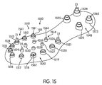
FIG. 15 is an isometric view of a preferred embodiment of outsole 1500. In some embodiments, outsole 1500 may include cleat system 1510. In some embodiments, cleat system 1510 may include first cleat group 1541, including cleats 1511-1517. Additionally, cleat system 1510 may include second cleat group 1542, including cleats 1518-1521. In some embodiments, cleat system 1510 may include third cleat group 1543, including cleats 1522-1525. Finally, in some embodiments, cleat system 1510 may include fourth cleat group 1544, including cleats 1526-1531.
Preferably, each of the cleat groups 1541-1544 may be associated with indentations. In some embodiments, first cleat group 1541 may be associated with first indentations 1561. In some embodiments, second cleat group 1542 may be associated with second indentations 1562. In some embodiments, third cleat group 1543 may be associated with third indentations 1563. Additionally, fourth cleat group 1544 may be associated with fourth indentations 1564.
Generally, the sizes of indentations 1561-1564 may vary. First indentations 1561 may be associated with indentation diameter 11. Likewise, second indentations 1562 may be associated with indentation diameter I2. In some embodiments, third indentations 1563 may be associated with indentation diameter 13. Finally, fourth indentations 1564 may be associated with indentation diameter I4. Generally, indentation diameter I4 is the smallest, with the diameters being ordered in ascending sizes as: I4, I1, I2, I3. Using this configuration, the traction applied by cleat system 1510 may be varied along each of the cleat groups 1541-1544.
Preferably, an outsole with a cleat system may include provisions for supplying internal structure along the outsole. In some embodiments, the outsole may include an internal structural plate. In some embodiments, the internal structural plate may be disposed along the length of the outsole. Preferably, the internal structural plate may include provisions for minimizing the pressure applied by the cleat system during use.
FIG. 16 is an exploded isometric view of a preferred embodiment of outsole 1600. Generally, outsole 1600 includes bottom portion 1602 associated with cleat system 1610, while top portion 1604 may be associated with a midsole or insole. Preferably, top portion 1604 may be disposed closer to a user's foot than bottom portion 1602.
In some embodiments, internal structural plate 1608 may be disposed between bottom portion 1602 and top portion 1604 of outsole 1600. Preferably, top portion 1604 and bottom portion 1602 are constructed as a single material that encases internal structural plate 1608. In a preferred embodiment, outsole 1600 may be constructed of a material that is molded around internal structural plate 1608.
Generally, internal structural plate 1608 may be a flex plate of some kind. In some embodiments, internal structural plate 1608 may be constructed of a material with a high rigidity. In some embodiments, internal structural plate 1608 may be constructed of a material with good response and some energy return. In a preferred embodiment, internal structural plate 1608 may be constructed of a nylon material with a glass fill.
The preferred positions of cleats 1611-1625 are shown along bottom portion 1602. Preferably, internal structural plate 1604 includes notches 1609 that are associated with cleats 1611-1614 and cleats 1617-1625. Notches 1609 are preferably configured in a manner that prevents any overlap between cleat system 1610 and internal structural plate 1608. This configuration prevents any cleat from cleat system 1610 from pressing against internal structural plate 1604 and creating undesired tension along outsole 1600.
Additionally, internal structural plate 1604 preferably includes provisions for facilitating flexibility along first portion 1640 of outsole 1600. In particular, internal structural plate 1604 preferably includes first extension 1630 and second extension 1632. Generally, first extension 1630 may be associated with a user's toes, and in particular the big toe. In a preferred embodiment, first extension 1630 may support the big toe. With this configuration, first extension 1630 may preferably prevent the big toe from undergoing hyperextension. Second extension 1632 may also be associated with a user's toes. Internal structural plate 1604 may also include gap 1650, disposed between first flange 1630 and second flange 1632.
The configuration of first flange 1630 and second flange 1632 along first portion 1640 of outsole 1600 preferably allow for increased flexibility along bending region 1660. Additionally, this configuration helps to prevent hyperextension of the user's foot in along first portion 1640. In this manner, internal structural plate 1604 preferably provides built-in turf toe protection.
While various embodiments of the invention have been described, the description is intended to be exemplary, rather than limiting and it will be apparent to those of ordinary skill in the art that many more embodiments and implementations are possible that are within the scope of the invention. Accordingly, the invention is not to be restricted except in light of the attached claims and their equivalents. Also, various modifications and changes may be made within the scope of the attached claims.

Claims (27)

1. An article of footwear comprising:
an outsole haying a forefoot portion, a heel portion, a medial side, a lateral side, and an outwardly facing outer surface, and defining an outer periphery;
a first cleat disposed on the outer surface of the outsole and at the outer periphery of the medial side of the forefoot portion;
the first cleat including a first tip portion and a first base portion;
wherein the first tip portion includes a first indentation;
wherein the first base portion has a first diameter;
a second cleat disposed on the outer surface of the outsole and at the outer periphery of the lateral side of the forefoot portion;
the second cleat including a second tip portion and a second base portion;
wherein the second tip portion includes a second indentation;
wherein the second base portion has a second diameter; and
wherein the second diameter is greater than the first diameter.
2. The article of footwear according to claim 1, wherein the first indentation is spherical.
3. The article of footwear according to claim 1, wherein the first cleat is spaced apart from the outer periphery a distance less than the first diameter, and wherein the second cleat is spaced apart from the outer periphery a distance less than the second diameter.
4. The article of footwear according to claim 1, wherein the first indentation is smaller than the second indentation.
5. The article of footwear according to claim 1, wherein the first cleat is one of a plurality of first cleats each having the first diameter;
wherein the second cleat is one of a plurality of second cleats each having the second diameter;
wherein the first cleats are disposed on the outer surface of the outsole along the outer periphery of the medial side of the forefoot portion in a line following a first contour of the outer periphery at the medial side of the forefoot portion; and
wherein the second cleats are disposed on the outer surface of the outsole along the outer periphery of the lateral side of the forefoot portion in a line following a second contour of the outer periphery at the lateral side of the forefoot portion.
6. The article of footwear according to claim 5, further comprising:
a plurality of third cleats disposed on the outer surface of the outsole and in the heel portion;
wherein each of the third cleats has a third diameter;
a plurality of fourth cleats disposed on the outer surface of the outsole and in the forefoot portion laterally between the plurality of first cleats and the plurality of second cleats;
wherein each of the fourth cleats has a fourth diameter;
wherein the third diameter is greater than each of the first diameter and the second diameter; and
wherein the fourth diameter is less than each of the first diameter, the second diameter, and the third diameter.
7. An article of footwear, comprising:
an outsole having a forefoot portion, a heel portion, a medial side, a lateral side, and an outwardly facing outer surface, and defining an outer periphery;
a plurality of first cleats disposed on the outer surface of the outsole and along the outer periphery of the medial side of the forefoot portion in a line following a first contour of the outer periphery at the medial side of the forefoot portion;
a plurality of second cleats disposed on the outer surface of the outsole and along the outer periphery of the lateral side of the forefoot portion in a line following a second contour of the outer periphery at the lateral side of the forefoot portion;
a plurality of third cleats disposed on the outer surface of the outsole and in the heel portion;
a plurality of fourth cleats disposed on the outer surface of the outsole and in the forefoot portion laterally between the plurality of first cleats and the plurality of second cleats;
wherein each of the first cleats and the second cleats extends from the outer surface a first length;
wherein each of the third cleats extends from the outer surface a second length;
wherein each of the fourth cleats extends from the outer surface a third length;
wherein the second length is greater than the first length; and
wherein the third length is less than the first length.
8. The article of footwear according to claim 7, wherein each cleat of the first, second, third, and fourth cleats has a tip portion comprising an outer periphery and an indented central portion.
9. The article of footwear according to claim 8, wherein the central portion is spherically indented and the outer periphery is flat.
10. The article of footwear according to claim 7, wherein the outer surface of the outsole in the forefoot portion is curved outwardly in a lateral direction from the medial side toward the lateral side and in a longitudinal direction from the forefoot portion toward the heel portion.
11. The article of footwear according to claim 7, wherein each first cleat of the plurality of first cleats has a first base portion having a first diameter;
wherein each second cleat of the plurality of second cleats has a second base portion having a second diameter;
wherein each third cleat of the plurality of third cleats has a third base portion having a third diameter;
wherein each fourth cleat of the plurality of fourth cleats has a fourth base portion having a fourth diameter;
wherein the second diameter is greater than the first diameter;
wherein the third diameter is greater than the second diameter; and
wherein the fourth diameter is less than the first diameter.
12. The article of footwear according to claim 11, wherein each first cleat is spaced apart from the outer periphery a distance less than the first diameter, and wherein each second cleat is spaced apart from the outer periphery a distance less than the second diameter.
13. The article of footwear according to claim 7, wherein each first cleat of the plurality of first cleats has an indented central portion of a first size;
wherein each second cleat of the plurality of second cleats has an indented central portion of a second size;
wherein each third cleat of the plurality of third cleats has an indented central portion of a third size;
wherein each fourth cleat of the plurality of fourth cleats has an indented central portion of a fourth size; and
wherein the first, second, third, and fourth sizes ascend in size from the fourth size, to the first size, to the second size, and to the third size.
14. An article of footwear comprising:
an outsole haying a front side, a rear side, a forefoot portion, a heel portion, a medial side, a lateral side, and an outwardly facing outer surface, and defining an outer periphery;
wherein the outsole comprises a top portion and a bottom portion, wherein the outer surface is on a side of the bottom portion opposite to the to portion;
a structural plate disposed between the to portion and the bottom portion of the outsole;
wherein the structural plate extends proximate to the outer periphery of the outsole in the forefoot portion and defines a notch at its edge;
at least one cleat disposed along an outer surface of the outsole;
the cleat including a tip portion;
the tip portion including a rim and a central portion;
wherein the central portion is indented and the rim is flat; and
wherein the at least one cleat is aligned with the notch.
15. The article of footwear according to claim 14, wherein the structural plate defines a plurality of notches at its edge proximate to the outer periphery of the outsole in the forefoot portion;
wherein the article of footwear further comprises a plurality of cleats disposed along the outer surface of the outsole in the forefoot portion; and
wherein each cleat of the plurality of cleats is aligned with a notch of the plurality of notches.
16. The article of footwear according to claim 14, wherein the central portion is spherically indented.
17. The article of footwear according to claim 14, wherein the structural plate extends proximate to the outer periphery of the outsole in the heel portion and defines a plurality of notches at its edge at the outer periphery of the outsole in the heel portion;
wherein the article of footwear further comprises a plurality of cleats disposed along the outer surface of the outsole in the heel portion; and
wherein each cleat of the plurality of cleats is aligned with a notch of the plurality of notches.
18. The article of footwear according to claim 14, wherein the top portion and the bottom portion of the outsole are constructed of a single material that encases the structural plate.
19. The article of footwear according to claim 14, wherein at the forefoot portion of the outsole, the structural plate defines a first extension on the medial side, a second extension on the lateral side, and a gap between the first extension and the second extension that is open to the front side of the outsole.
20. The article of footwear according to claim 19, wherein the first extension is aligned with a user's big toe and extends closer to the front side than does the second extension.
21. An article of footwear comprising:
an outsole having a forefoot portion, a heel portion, a medial side, a lateral side, and an outwardly facing outer surface, and defining an outer periphery;
a plurality of first cleats disposed on the outer surface of the outsole and along the outer periphery of the medial side of the forefoot portion in a line following a first contour of the outer periphery at the medial side of the forefoot portion;
a plurality of second cleats disposed on the outer surface of the outsole and along the outer periphery of the lateral side of the forefoot portion in a line following a second contour of the outer periphery at the lateral side of the forefoot portion;
each first cleat of the plurality of first cleats including a first tip portion and each second cleat of the plurality second cleats including a second tip portion;
each first tip portion of the plurality of first cleats including a first indentation and each second tip portion of the plurality of second cleats including a second indentation; and
wherein the first indentation is smaller than the second indentation.
22. The article of footwear according to claim 21, wherein the outer surface of the outsole is curved along a first portion of the outsole.
23. The article of footwear according to claim 21, wherein the first indentation is spherically indented.
24. The article of footwear according to claim 23, wherein the second indentation is spherically indented.
25. The article of footwear according to claim 22, further comprising a plurality of third cleats disposed on the outer surface of the outsole and in the heel portion;
wherein each third cleat of the plurality of third cleats has a tip portion defining a third indentation; and
wherein the third indentation is larger than the second indentation.
26. The article of footwear according to claim 25, further comprising a plurality of fourth cleats disposed on the outer surface of the outsole and in the forefoot portion laterally between the plurality of first cleats and the plurality of second cleats;
wherein each fourth cleat of the plurality of fourth cleats has a tip portion defining a fourth indentation; and
wherein the fourth indentation is smaller than the first indentation.
27. The article of footwear according to claim 26, wherein the each third cleat extends farther from the outer surface than each of the each first cleat, the each second cleat, and the each fourth cleat.
US11/683,967 2007-03-08 2007-03-08 Article of footwear with indented tip cleats Active 2029-04-09 US7802379B2 (en)

Priority Applications (1)

Application Number Priority Date Filing Date Title
US11/683,967 US7802379B2 (en) 2007-03-08 2007-03-08 Article of footwear with indented tip cleats

Applications Claiming Priority (1)

Application Number Priority Date Filing Date Title
US11/683,967 US7802379B2 (en) 2007-03-08 2007-03-08 Article of footwear with indented tip cleats

Publications (2)

Publication Number Publication Date
US20080216362A1 US20080216362A1 (en) 2008-09-11
US7802379B2 true US7802379B2 (en) 2010-09-28

Family

ID=39740199

Family Applications (1)

Application Number Title Priority Date Filing Date
US11/683,967 Active 2029-04-09 US7802379B2 (en) 2007-03-08 2007-03-08 Article of footwear with indented tip cleats

Country Status (1)

Country Link
US (1) US7802379B2 (en)

Cited By (9)

* Cited by examiner, † Cited by third party
Publication number Priority date Publication date Assignee Title
US20100293813A1 (en) * 2007-03-08 2010-11-25 Nike, Inc. Article Of Footwear With Multiple Cleat Sizes
US20130291405A1 (en) * 2011-03-08 2013-11-07 Admark Athletic Ventures Athletic shoe with athletic positioning cleat pattern
US20160021977A1 (en) * 2014-07-22 2016-01-28 Nike, Inc. Sole structure for an article of footwear including a shank
US20160338450A1 (en) * 2015-05-18 2016-11-24 Hsu-Tong Tu Method for shaping shoe spikes
US9743707B2 (en) 2012-01-24 2017-08-29 Jared C. Ballman Footwear cleat particularly for soccer
US9839255B2 (en) 2012-06-20 2017-12-12 Nike, Inc. Sole structure for article of footwear
US20190104806A1 (en) * 2017-10-06 2019-04-11 Wolverine Outdoors, Inc. Footwear with improved traction
US11096442B2 (en) 2010-04-14 2021-08-24 Ecco Sko A/S Sole for a golf shoe
USD936349S1 (en) * 2014-12-18 2021-11-23 Kahtoola, Inc. Shoe harness of a traction device

Families Citing this family (14)

* Cited by examiner, † Cited by third party
Publication number Priority date Publication date Assignee Title
US9149088B2 (en) 2011-09-16 2015-10-06 Nike, Inc. Medial rotational traction element arrangement for an article of footwear
US8984774B2 (en) * 2011-09-16 2015-03-24 Nike, Inc. Cut step traction element arrangement for an article of footwear
US9173450B2 (en) 2011-09-16 2015-11-03 Nike, Inc. Medial rotational traction element arrangement for an article of footwear
US9101178B2 (en) * 2011-11-23 2015-08-11 Nike, Inc. Article of footwear with a lateral offset heel stud
US20140216852A1 (en) * 2013-02-07 2014-08-07 GM Global Technology Operations LLC Impact resistant article
USD731769S1 (en) * 2014-10-23 2015-06-16 Skechers U.S.A., Inc. Ii Shoe outsole periphery and bottom
USD794317S1 (en) * 2015-06-09 2017-08-15 Allegiance Corporation Slipper tread
US10034520B1 (en) * 2017-01-14 2018-07-31 Javad Jafarifar Sports shoe with cleat
USD804790S1 (en) * 2017-04-21 2017-12-12 Nike, Inc. Shoe outsole
USD903293S1 (en) * 2018-07-02 2020-12-01 Griffiths & Nielsen Limited Anti-slip sole for a sock
JP2020141737A (en) * 2019-03-04 2020-09-10 美津濃株式会社 Outsole structure, manufacturing method therefor, and cleats shoes using outsole structure
USD899747S1 (en) * 2019-04-26 2020-10-27 Nike, Inc. Shoe
USD901868S1 (en) * 2019-04-26 2020-11-17 Nike, Inc. Shoe
USD937552S1 (en) * 2020-12-17 2021-12-07 Nike, Inc. Shoe

Citations (65)

* Cited by examiner, † Cited by third party
Publication number Priority date Publication date Assignee Title
US444735A (en) 1891-01-13 Voltaic insole
US1484785A (en) 1923-05-14 1924-02-26 John M Hiss Apparatus for supporting arches
US1848518A (en) 1932-03-08 Arch support
US2129424A (en) 1936-05-28 1938-09-06 Steven J Jay Arch support
US2179124A (en) * 1938-05-07 1939-11-07 Charles J Jesnig Bathtub slipper
US3043025A (en) * 1960-12-09 1962-07-10 William P Semon Article of manufacture with non-slip suction means
US3054197A (en) * 1958-04-21 1962-09-18 John T Riddell Inc Snap-on shoe cleat asembly
US3341952A (en) 1964-11-10 1967-09-19 Dassler Adolf Sport shoe, especially for football
US3410005A (en) 1965-04-14 1968-11-12 Ro Search Inc Golf shoe
US3988840A (en) 1975-05-07 1976-11-02 Hyde Athletic Industries, Inc. Sole construction
US3999558A (en) 1975-03-24 1976-12-28 Barnwell Joseph H Orthopedic shoe plate
US4014114A (en) 1975-11-28 1977-03-29 Three Line Research & Development Co., Inc. Spike cluster
US4083126A (en) * 1976-11-30 1978-04-11 The Raymond Lee Organization, Inc. Studded boots for firefighters
US4167071A (en) 1977-09-12 1979-09-11 Herbert Koransky Golf shoe
US4178702A (en) * 1976-12-22 1979-12-18 Bata-Schuh-Aktiengesellschaft Golf-shoe sole
US4233759A (en) 1979-02-07 1980-11-18 Adidas Sportschuhfabriken Adi Dassler Kg Outsoles for sports shoes, particularly for use on artificial grass
US4316335A (en) * 1979-04-05 1982-02-23 Comfort Products, Inc. Athletic shoe construction
US4318232A (en) * 1980-03-03 1982-03-09 Ching Yook J Heel structure for shoes
US4327503A (en) 1980-01-17 1982-05-04 Brs, Inc. Outer sole structure for athletic shoe
US4494320A (en) 1982-11-18 1985-01-22 8-Track Shoe Corp. Shoe outsole
US4524531A (en) 1982-12-02 1985-06-25 Vanderipe Donald R Golf shoes
US4597196A (en) 1984-08-24 1986-07-01 Northwest Podiatric Laboratories, Inc. Orthotic insert and method or making of the same
US4769931A (en) * 1987-08-06 1988-09-13 Morrow Donald W Cleated sole for footwear
US4787156A (en) 1984-11-07 1988-11-29 Kloeckner Ferromatik Desma Gmbh Sports shoe and methods for making the same
US4803747A (en) 1986-03-07 1989-02-14 Brown Dennis N Orthotic and method of making of the same
USD303871S (en) 1986-09-27 1989-10-10 Asahi Corporation Sole
US4875683A (en) 1988-07-12 1989-10-24 Wellman Edward F Golf club swing improvement apparatus
USD318946S (en) 1989-01-23 1991-08-13 Vibram S.P.A. Tread surface and periphery of a footwear unit sole
US5052130A (en) 1987-12-08 1991-10-01 Wolverine World Wide, Inc. Spring plate shoe
US5077916A (en) 1988-03-22 1992-01-07 Beneteau Charles Marie Sole for sports or leisure shoe
US5311680A (en) 1991-11-07 1994-05-17 Comparetto John E Dynamic orthotic
US5452526A (en) 1989-12-15 1995-09-26 Trisport Limited Footwear having an outsole stiffener
DE4417563A1 (en) 1994-05-19 1995-11-23 Uhl Sportartikel Karl Football boot with additional grips on sole
US5473827A (en) 1991-09-19 1995-12-12 Patrick International Outsole for sports shoes
US5853844A (en) 1997-05-23 1998-12-29 Wen; Keith Rubber pad construction with resilient protrusions
US5901472A (en) 1996-08-01 1999-05-11 Diversified Industrial Technology, Inc. Athletic shoe system and removable cleat
USD410965S (en) 1998-11-24 1999-06-15 The Timberland Company Portion of a shoe sole
US5915820A (en) 1996-08-20 1999-06-29 Adidas A G Shoe having an internal chassis
US5943794A (en) 1997-08-18 1999-08-31 Nordstrom, Inc. Golf shoes with aligned traction members
US6016613A (en) 1997-11-05 2000-01-25 Nike International Ltd. Golf shoe outsole with pivot control traction elements
EP1002473A1 (en) 1998-11-17 2000-05-24 LOTTO S.p.A. Device for increasing movement stability with shoes for tennis or similar sports
USD433213S (en) 2000-04-24 2000-11-07 The Timberland Company Element of shoe sole
US6167641B1 (en) 1997-12-11 2001-01-02 Softspikes, Inc. Athletic shoe cleat
US6199303B1 (en) 1999-02-05 2001-03-13 Adidas International B.V. Shoe with stability element
USD440032S1 (en) 2000-09-13 2001-04-10 Steven Madden, Ltd. Shoe sole
USD445561S1 (en) 2000-05-18 2001-07-31 Vibram S.P.A. Shoe sole
USD446917S1 (en) 2000-04-26 2001-08-28 L. L. Bean, Inc. Supportive sole insert for a shoe
US6381878B1 (en) 1997-09-03 2002-05-07 Spalding Sports Worldwide, Inc. Composite cleat for athletic shoe
US6421933B1 (en) 1999-10-12 2002-07-23 Lotto Sport Italia S.P.A. Insole for shoes for soccer, running or similar sports
US6434860B1 (en) * 1998-09-25 2002-08-20 Sun Standard, Inc. Removably mountable cleat
US6467196B1 (en) * 1998-08-06 2002-10-22 Yoshiki Koyama Spike ensuring stable kick during running and spike shoes
US6502330B1 (en) 1999-05-26 2003-01-07 Loic David Sole for footwear
US6543160B2 (en) 2001-04-05 2003-04-08 Price Advanced Innovations, Inc. Athletic shoe attachment
USD481201S1 (en) 2002-11-27 2003-10-28 Global Brand Marketing, Inc. Shoe bottom
US6647647B2 (en) * 2001-11-20 2003-11-18 Nike, Inc. Article of footwear with a ground-engaging member and method of altering a ground-engaging member
US20040163282A1 (en) * 2003-02-26 2004-08-26 Tang-Ma Pan Sole slide-proof device
US6857205B1 (en) 2002-05-09 2005-02-22 Nike, Inc. Article of footwear having a sole structure with a split plate
US20050097782A1 (en) 2003-11-06 2005-05-12 Elan-Polo, Inc. Athletic shoe having an improved cleat arrangement
US6910287B2 (en) 2000-08-09 2005-06-28 Ecco Sko A/S Shoe midsole
US6915598B2 (en) 2002-08-06 2005-07-12 Schering-Plough Healthcare Products Inc. Insole with arch spring
US6954998B1 (en) 2000-08-02 2005-10-18 Adidas International Marketing B.V. Chassis construction for an article of footwear
US7007410B2 (en) 2002-06-26 2006-03-07 Nike Inc. Article of footwear having a regional cleat configuration
US7100309B2 (en) 2004-01-16 2006-09-05 Nike, Inc. Track shoe with heel plate and support columns
US7143530B2 (en) 2003-07-25 2006-12-05 Nike, Inc. Soccer shoe having independently supported lateral and medial sides
USD539516S1 (en) 2004-10-12 2007-04-03 Columbia Insurance Company Outsole

Family Cites Families (1)

* Cited by examiner, † Cited by third party
Publication number Priority date Publication date Assignee Title
IT1216808B (en) * 1987-05-13 1990-03-14 Sviluppo Materiali Spa CONTINUOUS ELECTRODEPOSITION PROCESS OF METALLIC CHROME AND CHROMIUM OXIDE ON METAL SURFACES

Patent Citations (68)

* Cited by examiner, † Cited by third party
Publication number Priority date Publication date Assignee Title
US444735A (en) 1891-01-13 Voltaic insole
US1848518A (en) 1932-03-08 Arch support
US1484785A (en) 1923-05-14 1924-02-26 John M Hiss Apparatus for supporting arches
US2129424A (en) 1936-05-28 1938-09-06 Steven J Jay Arch support
US2179124A (en) * 1938-05-07 1939-11-07 Charles J Jesnig Bathtub slipper
US3054197A (en) * 1958-04-21 1962-09-18 John T Riddell Inc Snap-on shoe cleat asembly
US3043025A (en) * 1960-12-09 1962-07-10 William P Semon Article of manufacture with non-slip suction means
US3341952A (en) 1964-11-10 1967-09-19 Dassler Adolf Sport shoe, especially for football
US3410005A (en) 1965-04-14 1968-11-12 Ro Search Inc Golf shoe
US3999558A (en) 1975-03-24 1976-12-28 Barnwell Joseph H Orthopedic shoe plate
US3988840A (en) 1975-05-07 1976-11-02 Hyde Athletic Industries, Inc. Sole construction
US4014114A (en) 1975-11-28 1977-03-29 Three Line Research & Development Co., Inc. Spike cluster
US4083126A (en) * 1976-11-30 1978-04-11 The Raymond Lee Organization, Inc. Studded boots for firefighters
US4178702A (en) * 1976-12-22 1979-12-18 Bata-Schuh-Aktiengesellschaft Golf-shoe sole
US4167071A (en) 1977-09-12 1979-09-11 Herbert Koransky Golf shoe
US4233759A (en) 1979-02-07 1980-11-18 Adidas Sportschuhfabriken Adi Dassler Kg Outsoles for sports shoes, particularly for use on artificial grass
US4316335A (en) * 1979-04-05 1982-02-23 Comfort Products, Inc. Athletic shoe construction
US4327503A (en) 1980-01-17 1982-05-04 Brs, Inc. Outer sole structure for athletic shoe
US4318232A (en) * 1980-03-03 1982-03-09 Ching Yook J Heel structure for shoes
US4494320A (en) 1982-11-18 1985-01-22 8-Track Shoe Corp. Shoe outsole
US4524531A (en) 1982-12-02 1985-06-25 Vanderipe Donald R Golf shoes
US4597196A (en) 1984-08-24 1986-07-01 Northwest Podiatric Laboratories, Inc. Orthotic insert and method or making of the same
US4787156A (en) 1984-11-07 1988-11-29 Kloeckner Ferromatik Desma Gmbh Sports shoe and methods for making the same
US4803747A (en) 1986-03-07 1989-02-14 Brown Dennis N Orthotic and method of making of the same
USD303871S (en) 1986-09-27 1989-10-10 Asahi Corporation Sole
US4769931A (en) * 1987-08-06 1988-09-13 Morrow Donald W Cleated sole for footwear
US5052130A (en) 1987-12-08 1991-10-01 Wolverine World Wide, Inc. Spring plate shoe
US5077916A (en) 1988-03-22 1992-01-07 Beneteau Charles Marie Sole for sports or leisure shoe
US4875683A (en) 1988-07-12 1989-10-24 Wellman Edward F Golf club swing improvement apparatus
USD318946S (en) 1989-01-23 1991-08-13 Vibram S.P.A. Tread surface and periphery of a footwear unit sole
US5452526A (en) 1989-12-15 1995-09-26 Trisport Limited Footwear having an outsole stiffener
US5473827A (en) 1991-09-19 1995-12-12 Patrick International Outsole for sports shoes
US5311680A (en) 1991-11-07 1994-05-17 Comparetto John E Dynamic orthotic
DE4417563A1 (en) 1994-05-19 1995-11-23 Uhl Sportartikel Karl Football boot with additional grips on sole
US5901472A (en) 1996-08-01 1999-05-11 Diversified Industrial Technology, Inc. Athletic shoe system and removable cleat
US5915820A (en) 1996-08-20 1999-06-29 Adidas A G Shoe having an internal chassis
US5853844A (en) 1997-05-23 1998-12-29 Wen; Keith Rubber pad construction with resilient protrusions
US6354022B2 (en) 1997-08-18 2002-03-12 Nordstrom, Inc. Golf shoes with aligned traction members
US5943794A (en) 1997-08-18 1999-08-31 Nordstrom, Inc. Golf shoes with aligned traction members
US6381878B1 (en) 1997-09-03 2002-05-07 Spalding Sports Worldwide, Inc. Composite cleat for athletic shoe
US6016613A (en) 1997-11-05 2000-01-25 Nike International Ltd. Golf shoe outsole with pivot control traction elements
US6167641B1 (en) 1997-12-11 2001-01-02 Softspikes, Inc. Athletic shoe cleat
US6467196B1 (en) * 1998-08-06 2002-10-22 Yoshiki Koyama Spike ensuring stable kick during running and spike shoes
US6434860B1 (en) * 1998-09-25 2002-08-20 Sun Standard, Inc. Removably mountable cleat
EP1002473A1 (en) 1998-11-17 2000-05-24 LOTTO S.p.A. Device for increasing movement stability with shoes for tennis or similar sports
USD410965S (en) 1998-11-24 1999-06-15 The Timberland Company Portion of a shoe sole
US6199303B1 (en) 1999-02-05 2001-03-13 Adidas International B.V. Shoe with stability element
US6477791B2 (en) 1999-02-05 2002-11-12 Adidas International B.V. Shoe with stability element
US6502330B1 (en) 1999-05-26 2003-01-07 Loic David Sole for footwear
US6421933B1 (en) 1999-10-12 2002-07-23 Lotto Sport Italia S.P.A. Insole for shoes for soccer, running or similar sports
USD433213S (en) 2000-04-24 2000-11-07 The Timberland Company Element of shoe sole
USD471698S1 (en) 2000-04-26 2003-03-18 L. L. Bean, Inc. Supportive sole insert for a shoe
USD446917S1 (en) 2000-04-26 2001-08-28 L. L. Bean, Inc. Supportive sole insert for a shoe
USD445561S1 (en) 2000-05-18 2001-07-31 Vibram S.P.A. Shoe sole
US6954998B1 (en) 2000-08-02 2005-10-18 Adidas International Marketing B.V. Chassis construction for an article of footwear
US6910287B2 (en) 2000-08-09 2005-06-28 Ecco Sko A/S Shoe midsole
USD440032S1 (en) 2000-09-13 2001-04-10 Steven Madden, Ltd. Shoe sole
US6543160B2 (en) 2001-04-05 2003-04-08 Price Advanced Innovations, Inc. Athletic shoe attachment
US6647647B2 (en) * 2001-11-20 2003-11-18 Nike, Inc. Article of footwear with a ground-engaging member and method of altering a ground-engaging member
US6857205B1 (en) 2002-05-09 2005-02-22 Nike, Inc. Article of footwear having a sole structure with a split plate
US7007410B2 (en) 2002-06-26 2006-03-07 Nike Inc. Article of footwear having a regional cleat configuration
US6915598B2 (en) 2002-08-06 2005-07-12 Schering-Plough Healthcare Products Inc. Insole with arch spring
USD481201S1 (en) 2002-11-27 2003-10-28 Global Brand Marketing, Inc. Shoe bottom
US20040163282A1 (en) * 2003-02-26 2004-08-26 Tang-Ma Pan Sole slide-proof device
US7143530B2 (en) 2003-07-25 2006-12-05 Nike, Inc. Soccer shoe having independently supported lateral and medial sides
US20050097782A1 (en) 2003-11-06 2005-05-12 Elan-Polo, Inc. Athletic shoe having an improved cleat arrangement
US7100309B2 (en) 2004-01-16 2006-09-05 Nike, Inc. Track shoe with heel plate and support columns
USD539516S1 (en) 2004-10-12 2007-04-03 Columbia Insurance Company Outsole

Non-Patent Citations (2)

* Cited by examiner, † Cited by third party
Title
Dec. 15, 2009 Office Action from U.S. App. No. 11/683,965.
Photograph of "Nike Air Zoom Brasilian MG" shoes that were introduced to the public in Spring, 2006.

Cited By (12)

* Cited by examiner, † Cited by third party
Publication number Priority date Publication date Assignee Title
US20100293813A1 (en) * 2007-03-08 2010-11-25 Nike, Inc. Article Of Footwear With Multiple Cleat Sizes
US8584379B2 (en) * 2007-03-08 2013-11-19 Nike, Inc. Article of footwear with multiple cleat sizes
US11096442B2 (en) 2010-04-14 2021-08-24 Ecco Sko A/S Sole for a golf shoe
US20130291405A1 (en) * 2011-03-08 2013-11-07 Admark Athletic Ventures Athletic shoe with athletic positioning cleat pattern
US8707586B2 (en) * 2011-03-08 2014-04-29 Admark Athletic Ventures Athletic shoe with athletic positioning cleat pattern
US9743707B2 (en) 2012-01-24 2017-08-29 Jared C. Ballman Footwear cleat particularly for soccer
US9839255B2 (en) 2012-06-20 2017-12-12 Nike, Inc. Sole structure for article of footwear
US20160021977A1 (en) * 2014-07-22 2016-01-28 Nike, Inc. Sole structure for an article of footwear including a shank
USD936349S1 (en) * 2014-12-18 2021-11-23 Kahtoola, Inc. Shoe harness of a traction device
US20160338450A1 (en) * 2015-05-18 2016-11-24 Hsu-Tong Tu Method for shaping shoe spikes
US20190104806A1 (en) * 2017-10-06 2019-04-11 Wolverine Outdoors, Inc. Footwear with improved traction
US10492565B2 (en) * 2017-10-06 2019-12-03 Wolverine Outdoors, Inc. Footwear with improved traction

Also Published As

Publication number Publication date
US20080216362A1 (en) 2008-09-11

Similar Documents

Publication Publication Date Title
US7802379B2 (en) Article of footwear with indented tip cleats
US8584379B2 (en) Article of footwear with multiple cleat sizes
US20230078361A1 (en) Independently movable sole structure
US8375604B2 (en) Article of footwear with multiple cleat systems
US8789298B2 (en) Article of footwear with ball control portion
US10016020B2 (en) Article of footwear with forefoot secondary studs
US8333024B2 (en) Article of footwear for dancing
EP3153050B1 (en) Article of footwear with a medial rotational traction element arrangement
US8286371B2 (en) Article of footwear with cleat members
US8516723B2 (en) Midfoot insert construction
JP6169696B2 (en) Footwear articles with outsole with fin traction elements
US7954258B2 (en) Article of footwear with walled cleat system
EP2997844A1 (en) Stability and comfort system for an article of footwear
US8365442B2 (en) Cleat assembly
CN103619204A (en) An article of footwear with a ball contacting member

Legal Events

Date Code Title Description
AS Assignment

Owner name: NIKE, INC., MARYLAND

Free format text: ASSIGNMENT OF ASSIGNORS INTEREST;ASSIGNOR:GERBER, CLIFFORD B.;REEL/FRAME:019332/0276

Effective date: 20070430

STCF Information on status: patent grant

Free format text: PATENTED CASE

FPAY Fee payment

Year of fee payment: 4

MAFP Maintenance fee payment

Free format text: PAYMENT OF MAINTENANCE FEE, 8TH YEAR, LARGE ENTITY (ORIGINAL EVENT CODE: M1552)

Year of fee payment: 8

MAFP Maintenance fee payment

Free format text: PAYMENT OF MAINTENANCE FEE, 12TH YEAR, LARGE ENTITY (ORIGINAL EVENT CODE: M1553); ENTITY STATUS OF PATENT OWNER: LARGE ENTITY

Year of fee payment: 12