US7802230B1 - Heterogeneous software integration systems and methods - Google Patents
Heterogeneous software integration systems and methods Download PDFInfo
- Publication number
- US7802230B1 US7802230B1 US11/229,907 US22990705A US7802230B1 US 7802230 B1 US7802230 B1 US 7802230B1 US 22990705 A US22990705 A US 22990705A US 7802230 B1 US7802230 B1 US 7802230B1
- Authority
- US
- United States
- Prior art keywords
- component
- custom component
- application
- custom
- metadata
- Prior art date
- Legal status (The legal status is an assumption and is not a legal conclusion. Google has not performed a legal analysis and makes no representation as to the accuracy of the status listed.)
- Active, expires
Links
Images


Classifications
-
- G—PHYSICS
- G06—COMPUTING; CALCULATING OR COUNTING
- G06F—ELECTRIC DIGITAL DATA PROCESSING
- G06F8/00—Arrangements for software engineering
- G06F8/30—Creation or generation of source code
- G06F8/34—Graphical or visual programming
-
- G—PHYSICS
- G06—COMPUTING; CALCULATING OR COUNTING
- G06F—ELECTRIC DIGITAL DATA PROCESSING
- G06F9/00—Arrangements for program control, e.g. control units
- G06F9/06—Arrangements for program control, e.g. control units using stored programs, i.e. using an internal store of processing equipment to receive or retain programs
- G06F9/46—Multiprogramming arrangements
- G06F9/54—Interprogram communication
- G06F9/541—Interprogram communication via adapters, e.g. between incompatible applications
Definitions
- the present invention relates to integration of software, and in particular, to systems and methods for integrating heterogeneous software components.
- Computer programs i.e., software
- programs perform a wide variety of functions and may be used in applications ranging from the management of large volumes of business data for large companies to providing a rich information environment for individual users over the Internet.
- programs are often designed to interface with other programs so that one or both programs can use the features of the other.
- a main program will be hand coded by a programmer, and the programmer will include procedure or function calls to another program to include some or all of the other programs functionality in the main program.
- this traditional technique of hand coding interfaces between programs is expensive and tedious, and typically requires the skills of a highly trained programming professional.
- interfacing between the two programs can be a very complicated task. For example, communicating between different UI technologies (e.g. JavaScript, Java, .Net) is much more difficult that communicating between the same UI technology.
- UI technologies e.g. JavaScript, Java, .Net
- FIG. 1A is an example of a design tool 101 that may be used to develop software applications.
- Design tool 101 allows a user to graphically compose applications by dragging different components (e.g., User Interface (UI) elements) onto a drawing pane and connecting them with backend functionality.
- the composed application may be stored as metadata in a repository 102 .
- design tool 101 may read the metadata and automatically generate the program code for the application.
- the application may then be deployed across an enterprise for access by target users.
- This model driven approach allows for a rapid and error free software development and does not typically require advanced programming skills.
- FIG. 1B shows an existing design tool and deployment environment.
- a design tool 110 such as NetWeaverTM Visual Composer from SAP® provides a model driven approach for the graphical composition of applications.
- Composer 110 includes a set of visualization controls, ranging from buttons to animated pie charts that may be specified as part of an application.
- the resulting applications may be deployed on an enterprise portal 120 that allows access by clients 130 running web browsers, for example.
- Applications developed according to known techniques may be used to access and process information from a variety of data sources 140 using connectivity software 150 (sometimes referred to as “middleware”) at runtime.
- middleware layer 150 provides an integration platform and interface between applications and provides a runtime environment.
- Middleware layer 150 interoperates with applications created using design tool 110 , which may include applications in .NET, J2EE, WebSphere, HTTP, XML, or Web services, for example.
- design tool 110 may include applications in .NET, J2EE, WebSphere, HTTP, XML, or Web services, for example.
- the design tool 110 compiler enables generation of application programs that can be deployed to the portal 120 . Once deployed, the application programs created by design tool 110 can retrieve data from the portal 120 and connectivity framework 150 and display this information just like any other hand-coded portal pages.
- FIG. 2 shows a graphical user interface of an existing design tool.
- Design tool 200 facilitates the creation of content for the Enterprise Portal 120 using a visual user interface rather than manually writing code.
- Design tool 200 provides sophisticated, yet simple-to-use tools for creating application programs (sometimes referred to as portlets or iViews) that communicate with other applications to move information from one program to another, combine data, and/or display data (e.g., to a page).
- An example design tool 200 may operate on top of the Enterprise Portal, utilizing the portal's connector-framework interfaces to allow users to access a range of internal and external databases or other data services.
- Applications can be created using an easy drag-drop-connect paradigm. Users may select from a variety of components for specifying data sources (e.g., “Data Services”), operations, formulas, models, connectors, and views for defining an application. For example, as shown in FIG. 2 , a user may specify a source 201 that outputs the top N sales by selecting and configuring a visual object representing a desired source. An output port on the source may be connected to an input port on a selected and configured view of the data 202 . View 202 may display the data in a pie chart format, for example. The models are then compiled into executable code and deployed.
- data sources e.g., “Data Services”
- operations, formulas, models, connectors, and views for defining an application.
- FIG. 2 a user may specify a source 201 that outputs the top N sales by selecting and configuring a visual object representing a desired source.
- An output port on the source may be connected to an input port on a selected and configured view of the data
- One problem with existing design tools is that the components available to a user in the design tool's palette are fixed.
- the only components available to a user of the design tool are components that have been specifically designed to work with the particular design tool (i.e., components created by the design tool provider).
- many users may find that the content of a design tool's control palette is too limited for the desired application.
- application requirements may mandate specific functionality or data visualizations to better and more intuitively present information to the end-user.
- Customers requiring enhanced functionality generally must submit a development request to the design tool provider.
- custom components i.e. custom components
- custom components cannot communicate with the design tool because they do not share a common interface.
- custom components it is not currently possible to incorporate custom components into the design tools palette of available components.
- third party components are programmed, in any of a variety of programming languages, interfacing these components with applications requires hand coding, which is time consuming and expensive.
- Embodiments of the present invention improve integration of heterogeneous software components.
- the present invention includes a computer-implemented method comprising receiving metadata that defines an interface for communicating with a custom component, mapping information between the custom component and at least one other program component of an application, and generating wrapper code based on the metadata and the mapping, wherein the wrapper code communicates information between the custom component and the application.
- the custom component is a custom display component.
- the information mapped between the custom component and program includes at least one attribute.
- the metadata is stored in a computer file having a predefined schema, such as XML, for example. The metadata may be used to specify a technology for the custom component, one or more ports for the custom component, or one or more properties for the custom component.
- the metadata specifies a technology for the custom component, one or more ports for the custom component, or one or more properties for the custom component.
- the method further comprises displaying a first visual object corresponding to the custom component in a graphical user interface, wherein the first visual object includes at least one of an input port or output port.
- the custom component is in a first programming language and the application is in a second programming language.
- the wrapper comprises a first component for communicating with the custom component and a second component for communicating with the application.
- the wrapper converts commands between technologies such as HTML, Java, .NET, Flash, or ActiveX, for example.
- the present invention includes a computer-readable medium containing instructions for controlling a computer system comprising code for receiving metadata that defines an interface for communicating with a custom component, code for displaying a visual object corresponding to the custom component in a graphical user interface, code for mapping the visual object corresponding to the custom component to at least one other visual object to define an application, and code for generating the application and a wrapper based on the metadata and the mapping, wherein the wrapper communicates information between the custom component and the application.
- the custom component is a custom display component.
- the metadata is stored in a computer file having a predefined schema.
- the first visual object includes at least one of an input port or output port.
- a port includes a one or more of attributes, and a user specifies attributes transferred between visual object ports in the mapping.
- mapping is stored as metadata in a repository, and the design tool generates the application and the wrapper using the mapping metadata and metadata that defines the custom component.
- the wrapper comprises a first component for communicating with the custom component and a second component for communicating with the application.
- the present invention includes a computer system comprising an application server coupled to one or more client computers over a network, a custom component, a metadata file having a predefined schema, wherein the metadata file includes information for communicating with the custom component, and a design tool, wherein the design tool generates wrapper code based on the metadata file for communicating information between the custom component and the application, wherein the custom component is stored on a server, and an application communicates with the custom component through the wrapper.
- the application and wrapper are stored on the server.
- the application and at least a part of the wrapper is stored on a client computer.
- the application accesses resources in at least one database system, an ERP system, a CRM system, a SCM system, or any other application.
- the custom component is a custom display component.
- FIG. 1A is an example of a design tool that may be used to develop software applications.
- FIG. 1B shows an existing design tool and deployment environment.
- FIG. 2 shows a graphical user interface of an existing design tool.
- FIG. 3A illustrates integration of a custom component according to one embodiment of the present invention.
- FIG. 3B illustrates a client-server design time environment according to one embodiment of the present invention.
- FIG. 3C illustrates a client-server run time environment according to one embodiment of the present invention.
- FIG. 4 illustrates method according to one embodiment of the present invention.
- FIG. 5 illustrates a metadata schema according to one embodiment of the present invention.
- FIGS. 6A-D illustrate how a custom component may be integrated in a design tool and how an application is presented to users according to one embodiment of the present invention.
- FIG. 7 illustrates an application integrated with a custom display component according to one embodiment of the present invention.
- FIG. 8 illustrates the integration of an application and custom display component according to one embodiment of the present invention.
- FIG. 9 illustrates using a wrapper to integrate applications and custom components in a variety of different technologies according to one embodiment of the present invention.
- FIGS. 10A-E show an example of an integrated custom component according to one embodiment of the present invention.
- FIG. 11 illustrates an application and custom component deployed in a computer system according to one embodiment of the present invention.
- FIG. 12 illustrates a design tool and custom components integrated into an enterprise software system according to one embodiment of the present invention.
- FIG. 3A illustrates integration of a custom component according to one embodiment of the present invention.
- the term component means a portion (or part) of a software program or system.
- An example of a component may be one or more blocks of code (or even a single line of code in some cases) for performing a particular function.
- a custom component is an external component that has been designed independently of, and in a different technology than, the programming application (herein, “application”) into which it is being integrated, and performs one or more particular operations that may be useful to the programming application.
- a custom component 305 is provided together with metadata 304 to a design tool 301 . Metadata is data about data, and may be used for a variety of purposes.
- the metadata 304 defines an interface for communicating with a custom component so that the custom component can be incorporated into design tool 301 .
- a custom component 305 and metadata 304 corresponding to the custom component 305 may be stored in a container 303 (e.g., a “zip file”).
- Design tool 301 may include a metadata retrieval component 308 for retrieving metadata 304 and storing it in metadata repository 302 .
- a user may invoke design tool 301 for creating an application.
- Design tool 301 may be used to specify a variety of features and functions of an application, such as data sources, operations, formulas, models, connectors, or views, for example.
- Embodiments of the present invention allow a user to incorporate one or more custom components 305 into the design tool and resulting application.
- Design tool 301 may store the specification for the application (i.e., an application definition) as metadata in repository 302 .
- the metadata defining the application is used to generate executable code for the application 320 .
- the custom component's metadata 304 may be accessed by design tool 301 to generate wrapper code 321 for communicating information (e.g., data or commands) between the custom component and the application.
- a wrapper is a software component that acts as an interface between a custom component and an application.
- the output of design tool 301 includes an application program 320 and wrapper code 321 .
- Application program 320 may communicate with custom component 322 through the automatically generated wrapper code 321 .
- FIG. 3B illustrates a client-server design time environment according to one embodiment of the present invention.
- a client computer system 350 may include design tool 351 for allowing users to design software applications.
- Design tool 351 includes a custom component plug-in 352 that allows a user to integrate custom components into the designs.
- the container for the custom component metadata 372 is stored remotely on a server 370 (e.g., in a repository).
- a user may incorporate the custom component into the design tool by accessing a custom component administrator program 371 across network 360 .
- the administrator 371 may store access information for each available custom component, including path names for all relevant files and the type of container, if any, that the custom component and metadata are stored in.
- Custom component plug-in 352 may include a variety of features to support integration of custom components, including code for retrieving the custom components metadata, translating the metadata into a format used by the design tool, and generating the wrapper code used to communicate information between the custom component and the application.
- FIG. 3C illustrates a client-server run time environment according to one embodiment of the present invention.
- the design tool automatically generates the code for the application. If a custom component is incorporated into the design, the design tool also uses the custom control metadata and other information about the application (e.g., information about the mapping described below) to generate wrapper code that integrates the custom component with the application.
- an application 320 , custom component 322 , and wrapper 321 are deployed across a computer system including a client computer 350 coupled to a server computer 370 over a network 380 . It is to be understood that a variety of deployment techniques could be used.
- the application 320 and wrapper 321 are deployed on client 350 , and custom component 322 is deployed on server 370 .
- a browser 390 may be invoked on client 350 , and application 320 may be executed by the browser.
- the application may interface with the custom component 322 using wrapper 321 .
- wrapper 321 may be used to pass data between application 320 and custom component 322 , or invoke procedures or functions of the custom component. Wrapper 321 may also translate instructions between technologies.
- part of the communication function performed by wrapper 321 includes converting commands between technologies such as HTML, Java, .NET, Flash, or ActiveX, for example. While embodiments of the present invention include components that work with a browser, it is to be understood that the invention is not limited to browser based technologies.
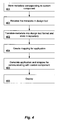
- FIG. 4 illustrates method according to one embodiment of the present invention.
- metadata corresponding to a custom component is stored on a computer system.
- a design tool receives the metadata. For example, as mentioned above a user may retrieve the metadata into the design tool to incorporate a custom component into a design.
- the metadata may be translated into a native format used by the design tool and stored in a repository. Since design tools typically represent designs using metadata, the design tool will typically have a native format for such representations. To more efficiently incorporate a custom component into the design tool, it may be advantageous to receive the metadata corresponding to the custom component, and store the metadata in the native format.
- a mapping for the application is created.
- a mapping is a specification of the components used in an application and the relationship between such components.
- a mapping includes visual objects corresponding to software components coupled together in a graphical user interface. Each component in the mapping may have input and/or output ports for communicating information (e.g., attributes) between the components.
- Some embodiments of the present invention include mappings having a variety of components, including components that are native to the design tool environment and custom components that have been incorporated into the design tool environment.
- the design tool generates the code for the application and wrapper.
- the application, wrapper, and custom component may be deployed for execution on one or more computer systems.
- FIG. 5 illustrates a metadata schema according to one embodiment of the present invention.
- the metadata defines an interface to the custom component, and may describe which data a particular custom component both expects at run time and which data it produces at run time, for example.
- the interface is defined either by the custom component developer or by a design tool administrator for each custom component.
- the metadata corresponding to the custom component may be formatted according to a particular predefined structure (i.e., a schema) so that the design tool may more readily access the metadata. For instance, if different custom components include particular information required by the design tool, and if that information is stored in a predefined structure understood by the design tool, then the design tool can efficiently access different metadata files for different custom components.
- the metadata may include information needed by the design tool to incorporate the custom component into the design tool's environment and information for generating code for the wrapper.
- Example metadata schema 500 illustrates the structure and information that may be used.
- the metadata may include tags for specifying the title, the custom component's starting filename as well as the technology that the custom component was developed in (e.g., Flash, .NET, Java).
- the title may be used to identify the custom component to the user of the design tool.
- the state filename may be included to specify the name of the file within the custom component's container that will start (render) the custom component when pointed to via a web browser, for example.
- the communication between the design tool application and the custom component may be different. Specifying the technology tag indicates which communication wrappers should be generated (e.g., Flash or Dynamic HTML).
- the port tag may be used to declare the data flow for the custom component. Data the custom component consumes is declared as an input port, and data the custom component produces is declared as output port.
- a port is a software construct for specifying data inputs and outputs. Each port may include a set of fields which will contain the data when transferred between the application and the custom component. Table 2 shows an example of children of the port tag.
- Example id This tag specifies what id will be used for input_data referencing the port by the custom component.
- title The title identifies the port to the design Heat Map Input tool user.
- type The type specifies whether the port is for input_set input into the custom component or output from the custom component.
- This tag may also specify the cardinality of the data passed between the custom component and the application, the data can be in the form of a table as a set of data, or as a one-to- one mapping between the field and value.
- Each port despite its type, can have 0 or more fields. Each field can be thought of as a column in table or a single field in a form.
- the id of the field may be referenced by regional_average the custom component and be displayed in the port properties when selected by the design tool user.
- the metadata may be stored in an XML file. Accordingly, the interface is declared using an XML file (e.g., metadata.xml), and the XML format is defined by an XML Schema Definition (XSD) file.
- XML file e.g., metadata.xml
- XSD XML Schema Definition
- FIGS. 6A-D illustrate how a custom component may be integrated in a design tool according to one embodiment of the present invention.
- the design tool may display available components and connectors to a user in a tool palette, and a user may drag items from the tool palette to a design pane 610 (also referred to as a “storyboard”).
- a native component for sourcing data 602 (“get Prices”) produces a sequence of prices on an output port “Values.”
- the output port of source 602 is coupled to the input port of another native component 603 for displaying the data in a table.
- a user may incorporate a custom component 601 into the design environment.
- FIG. 6B shows a custom component that has been brought onto the storyboard.
- an additional custom component available in a custom component repository and registered by the component administrator may be added to the design tool for viewing and for including in an application.
- a custom component discovery pane 620 is displayed, listing all available custom components from the repository. Each component can be dragged onto the storyboard and used in the design tool environment for modeling. The end user only needs to know that additional components are available.
- the user may use a drop down menu in discovery pane 620 to associate a particular custom component with the visual object of the custom component displayed in the storyboard.
- a user has associated the custom component “Oil Barrel Chart” with the visual custom component object 602 .
- the custom component discovery pane 620 may connect via HTTP to the custom component plug-in (see FIG. 3B ) running on the design tool.
- the plug-in may provide the custom component's details including all metadata so that when a custom component is dragged to the storyboard all properties and ports can be created. Therefore, the custom component plug-in provides, among other things, a generic extension mechanism to the palette.
- FIG. 6C shows a custom component 602 included in a model for an application.
- the model provides a graphical representation of dataflow, visualization, and events.
- a mapping may include the graphical representation of the components on the storyboard, and may further include the underlying information for coupling the components together (e.g., the storyboard metadata).
- Custom component 602 is included in a mapping for the application. For instance, the custom component has an input port coupled to the output port of the source component.
- custom component 602 is a custom display component for presenting data from the source in a particular style of display (e.g., as oil barrel), the functionality of which is provided by the custom component.
- the input port of the custom component may be mapped to particular attributes (i.e., “Fields”) at the output of the source.
- An attribute is a changeable property or characteristic of a component (e.g., a custom component) that can be set to different values.
- mapping pane 630 shows that the “location” attribute of the custom component input port is mapped to the “country” output of the source (i.e., @COUNTRY).
- the “sold” attribute of the custom component input port is mapped to the “price” output of the source (i.e., @PRICE). Accordingly, the inputs to the custom component are defined, and these definitions may be used to generate executable code for passing the specified input data to the custom component at runtime for display.
- 6D shows the output of the custom component at run time.
- the price is display using oil barrels rather than a simple bar chart that may be available in the design tools native environment.
- FIG. 7 illustrates integration of an application with a custom display component according to one embodiment of the present invention.
- a custom display component is a custom component that provides customized data display capabilities, such as the oil barrel display in the previous example.
- design tool 701 retrieves metadata 704 corresponding to custom display component 705 , which may be stored together in a container 703 .
- the metadata 704 may be converted into a local format by design tool 701 and stored in repository 702 .
- a user may compose applications by mapping together visual objects corresponding to native or custom components. The mapping may also be stored as metadata.
- mapping metadata which may include metadata about the custom component in a particular application (e.g., see FIG. 10D below).
- the design tool may then generate actual programming code from the mapping defined by associated metadata.
- the design tool may generate an application 710 and a wrapper based on the mapping and custom control metadata stored in repository 702 .
- the wrapper may be used for interfacing between the custom component 730 and the application 710 .
- the wrapper includes two interface programs 720 A and 720 B.
- the first interface program 720 A communicates with application program 710
- the second interface program communicates with custom component 730 .
- the application side interface 720 A and custom component side interface 720 B “wrap” around the custom component to facilitate integration of the custom component 730 with application 710 .
- FIG. 9 illustrates using a wrapper to integrate applications and custom components in a variety of different technologies according to one embodiment of the present invention.
- a two-part wrapper may be used to create an “any-to-any” integration layer.
- a user may configure the design tool to generate an application in any of a variety of technologies including Flash, DHTML, HTML, ActiveX, .NET, or Java., to name just a few possibilities.
- the custom component may be in a different technology than the application is targeted for.
- a first interface program 720 A may be automatically generated to communicate with an application generated by the design tool in Flash, for example, and a second interface program 720 B may be automatically generated to communicate with a custom component in Java.
- the communication function of the wrapper may include translating commands between different technologies.
- a two-part wrapper allows the application side interface to handle communications from the application, and the custom component side interface handles the communications to the custom control. Accordingly, an application may be implemented in any technology and still be able to communicate with custom controls implemented in a different technology. While the above example illustrates custom components that are implemented using user interface technologies that work with a browser, it is to be understood that the invention is not limited to UI technologies that are displayed in the browser.
- FIG. 10A illustrates a custom component incorporated into a design tool according to one embodiment of the present invention.
- Custom component 1000 has been incorporated into the design tool and dragged onto storyboard 1010 .
- Discovery pane 1020 illustrates the properties of the custom component, such as the title of the component, “Advanced Worklist,” and other properties such as the number of rows that may be viewed, for example.
- the custom component in this example has two input ports and one output port.
- the first input port, “create task,” has three fields: a due date, subject, and priority.
- the second input port, “search tasks,” has one field: a search term.
- the output port, “search results,” has five fields: due, from, priority, sent, and subject.
- FIG. 10B-C show an example of the metadata corresponding to custom component 1000 , which may be stored in a container with the custom component in an XML file using the schema described in FIG. 5 .
- FIG. 10D shows an example of the metadata after it has been retrieved and stored in the design tools native format.
- FIG. 10E shows an example of a custom component side interface 720 B of FIG. 7 for custom component 1000 .
- This example wrapper is automatically generated by a design tool to support communications with a Flash based custom component.
- the “SetVariable” line in code 1060 is a Flash call to a method in the custom component. Code 1060 , therefore, may be used to communicate information to the Flash custom component.
- code 1050 and 1051 is the output handler used to communicate information from the custom component to the application side interface of the wrapper.
- VBScript is used to call outside the Flash custom component.
- the VBScript includes a JavaScript function call (“comp — 9_DoFSCommand”) that invokes code 1051 , which is a JavaScript call back to the application side interface of the wrapper. It is to be understood that different technologies for the application and custom component will result in different commands in different languages being used within the wrapper, and that the present invention is not limited to any particular language.
- FIG. 11 illustrates an application and custom component deployed in a computer system according to one embodiment of the present invention.
- a wrapper 1114 for the custom component 1113 is created by design tool 1101 .
- the wrapper and custom component may be copied to a server 1110 for reference at run-time (e.g., in the server's web directory).
- the server may further include a web portal 1111 for controlling the execution of applications on the server by remote users.
- Applications 1112 or custom components 1113 may access a variety of resources including data from databases 1121 - 1122 through database management system 1120 .
- the application 1112 is deployed to server 1110 (e.g., a production server), and the client computers 1130 - 1170 may reference application 1112 from the server.
- local applications 1131 - 1171 it is possible to deploy local applications 1131 - 1171 to clients 1130 - 1170 .
- application 1112 on server 1110 or local applications 1131 - 1171 on clients 1130 - 1170 may communicate with custom component 1113 using wrapper 1114 , for example.
- Applications generated by design tool 1101 integrate seamlessly with the custom component at run time with the help of the generated wrapper.
- the wrapper handles the two-way communication between applications and the custom component by acting as an adapter for a given technology (e.g., a UI technology) of the custom component. This allows a custom component written in DHTML to talk with the application written in Flash, for example, without the custom component having to write Flash specific communication code.
- FIG. 12 illustrates a design tool and custom components integrated into an enterprise software system according to one embodiment of the present invention.
- a design tool 1210 may be used to generate applications that draw on resources available from a variety of available systems such as, for example, databases 1211 , enterprise resource planning (ERP) systems 1212 , customer relationship management (CRM) systems 1213 , supply chain management (SCM) systems 1214 , or any other application.
- Custom components 1221 may be integrated into design tool 1210 to generate applications 1220 with even more functionality.
- Example applications may include accounting applications 1230 , purchasing applications 1240 , or planning applications 1250 to name just a few.
Abstract
Description
| TABLE 1 | ||
| Tag | Description | Example |
| id | This tag specifies what id will be used for | initial_location |
| referencing the property by the custom | ||
| control. In some cases this data may be | ||
| passed via a query string, in this case the | ||
| name in the query string is the id specified | ||
| here. | ||
| title | The title identifies the property to the | Initial Location |
| design tool user. | ||
| type | Specifies a restriction on the parameter's | String |
| value type, possible values are “string”, | ||
| “number” and “Boolean.” | ||
| default value | This is the default value displayed to the | California |
| user in design tool. | ||
| TABLE 2 | ||
| Tag | Description | Example |
| id | This tag specifies what id will be used for | input_data |
| referencing the port by the custom | ||
| component. | ||
| title | The title identifies the port to the design | Heat Map Input |
| tool user. | ||
| type | The type specifies whether the port is for | input_set |
| input into the custom component or output | ||
| from the custom component. This tag may | ||
| also specify the cardinality of the data | ||
| passed between the custom component and | ||
| the application, the data can be in the form | ||
| of a table as a set of data, or as a one-to- | ||
| one mapping between the field and value. | ||
| field | Each port, despite its type, can have 0 or | |
| more fields. Each field can be thought of | ||
| as a column in table or a single field in a | ||
| form. | ||
| field.id | The id of the field may be referenced by | regional_average |
| the custom component and be displayed in | ||
| the port properties when selected by the | ||
| design tool user. | ||
In one embodiment, the metadata may be stored in an XML file. Accordingly, the interface is declared using an XML file (e.g., metadata.xml), and the XML format is defined by an XML Schema Definition (XSD) file.
Claims (18)
Priority Applications (1)
| Application Number | Priority Date | Filing Date | Title |
|---|---|---|---|
| US11/229,907 US7802230B1 (en) | 2005-09-19 | 2005-09-19 | Heterogeneous software integration systems and methods |
Applications Claiming Priority (1)
| Application Number | Priority Date | Filing Date | Title |
|---|---|---|---|
| US11/229,907 US7802230B1 (en) | 2005-09-19 | 2005-09-19 | Heterogeneous software integration systems and methods |
Publications (1)
| Publication Number | Publication Date |
|---|---|
| US7802230B1 true US7802230B1 (en) | 2010-09-21 |
Family
ID=42734044
Family Applications (1)
| Application Number | Title | Priority Date | Filing Date |
|---|---|---|---|
| US11/229,907 Active 2028-09-26 US7802230B1 (en) | 2005-09-19 | 2005-09-19 | Heterogeneous software integration systems and methods |
Country Status (1)
| Country | Link |
|---|---|
| US (1) | US7802230B1 (en) |
Cited By (33)
| Publication number | Priority date | Publication date | Assignee | Title |
|---|---|---|---|---|
| US20100095267A1 (en) * | 2008-10-15 | 2010-04-15 | International Business Machines Corporation | Describing formal end-user requirements in information processing systems using a faceted, tag-based model |
| US20100095269A1 (en) * | 2008-10-15 | 2010-04-15 | International Business Machines Corporation | Faceted, tag-based approach for the design and composition of components and applications in component-based systems |
| US20100293528A1 (en) * | 2009-05-18 | 2010-11-18 | Austin Paul F | Hosting a Graphical Program Execution System on an Embedded Device |
| US20100318370A1 (en) * | 2009-06-11 | 2010-12-16 | International Business Machines Corporation | Web service interaction in a dynamically extensible business application |
| US20110010724A1 (en) * | 2009-07-13 | 2011-01-13 | Sudhindra Kumar Thokur Lakshminarayanan | Communication bridge |
| US20110271184A1 (en) * | 2010-04-28 | 2011-11-03 | Microsoft Corporation | Client application and web page integration |
| US20120030655A1 (en) * | 2010-07-29 | 2012-02-02 | De Castillo Alejandro | Generating and Modifying Textual Code Interfaces from Graphical Programs |
| US20120159312A1 (en) * | 2010-12-17 | 2012-06-21 | Microsoft Corporation | Representation of an interactive document as a graph of entities |
| US20120198351A1 (en) * | 2011-01-31 | 2012-08-02 | Oracle International Corporation | Automatically Testing a Web Application That Has Independent Display Trees |
| US8290905B1 (en) * | 2009-09-11 | 2012-10-16 | Infragistics Inc. | Method and system for accessing interface design elements |
| US20120310709A1 (en) * | 2011-04-22 | 2012-12-06 | International Business Machines Corporation | Computer-implemented method and apparatus for integrating heterogeneous business processes |
| US20130055201A1 (en) * | 2011-08-29 | 2013-02-28 | Salesforce.Com, Inc. | Custom application creation in multi-tenant systems |
| US20130117291A1 (en) * | 2011-11-03 | 2013-05-09 | Salesforce.Com, Inc. | System, method and computer program product for defining applications using metadata records created from an object specifying a predefined metadata format |
| US8527943B1 (en) * | 2004-02-12 | 2013-09-03 | Raju V. Chiluvuri | System and method of application development |
| WO2013185016A1 (en) * | 2012-06-08 | 2013-12-12 | Alibaba Group Holding Limited | Method and device for publishing and implementing wireless application |
| US20140157225A1 (en) * | 2012-07-02 | 2014-06-05 | Avrom Roy-Faderman | Custom Metametadata with Packagable Records |
| US8776015B1 (en) * | 2007-02-08 | 2014-07-08 | The Mathworks, Inc. | Pattern modeling methods and systems |
| US20140280373A1 (en) * | 2013-03-15 | 2014-09-18 | John Raitto | Automatically determining an optimal database subsection |
| US9024952B2 (en) | 2010-12-17 | 2015-05-05 | Microsoft Technology Licensing, Inc. | Discovering and configuring representations of data via an insight taxonomy |
| US9069557B2 (en) | 2010-12-17 | 2015-06-30 | Microsoft Technology Licensing, LLP | Business intelligence document |
| US9104992B2 (en) | 2010-12-17 | 2015-08-11 | Microsoft Technology Licensing, Llc | Business application publication |
| US9110957B2 (en) | 2010-12-17 | 2015-08-18 | Microsoft Technology Licensing, Llc | Data mining in a business intelligence document |
| US9111238B2 (en) | 2010-12-17 | 2015-08-18 | Microsoft Technology Licensing, Llc | Data feed having customizable analytic and visual behavior |
| USD741902S1 (en) * | 2013-11-01 | 2015-10-27 | Yokogawa Electric Corporation | Portion of display screen with an icon |
| US9171272B2 (en) | 2010-12-17 | 2015-10-27 | Microsoft Technology Licensing, LLP | Automated generation of analytic and visual behavior |
| US9304672B2 (en) | 2010-12-17 | 2016-04-05 | Microsoft Technology Licensing, Llc | Representation of an interactive document as a graph of entities |
| WO2016210194A1 (en) * | 2015-06-26 | 2016-12-29 | Microsoft Technology Licensing, Llc | Automated components-based application deployment in a cloud based on the application architecture |
| US9864966B2 (en) | 2010-12-17 | 2018-01-09 | Microsoft Technology Licensing, Llc | Data mining in a business intelligence document |
| US20180121170A1 (en) * | 2016-10-31 | 2018-05-03 | General Electric Company | System architecture for secure and rapid development, deployment and management of analytics and software systems |
| US10048854B2 (en) | 2011-01-31 | 2018-08-14 | Oracle International Corporation | Drag and drop interaction between components of a web application |
| US10289460B2 (en) | 2016-11-15 | 2019-05-14 | Microsoft Technology Licensing, Llc | System integration using configurable dataflow |
| US10311107B2 (en) | 2012-07-02 | 2019-06-04 | Salesforce.Com, Inc. | Techniques and architectures for providing references to custom metametadata in declarative validations |
| US10628504B2 (en) | 2010-07-30 | 2020-04-21 | Microsoft Technology Licensing, Llc | System of providing suggestions based on accessible and contextual information |
Citations (13)
| Publication number | Priority date | Publication date | Assignee | Title |
|---|---|---|---|---|
| US6023271A (en) * | 1998-06-11 | 2000-02-08 | Sun Microsystems, Inc. | Framework for binding data viewers/data manipulation with one to many objects through introspection |
| US20030023953A1 (en) * | 2000-12-04 | 2003-01-30 | Lucassen John M. | MVC (model-view-conroller) based multi-modal authoring tool and development environment |
| US6564368B1 (en) * | 1998-10-01 | 2003-05-13 | Call Center Technology, Inc. | System and method for visual application development without programming |
| US20040015858A1 (en) * | 2002-02-13 | 2004-01-22 | International Business Machines Corporation | Configuration model for configuring an adapter software component to selectively access software objects and object editor using instance of same |
| US20040015833A1 (en) * | 1996-03-19 | 2004-01-22 | Dellarocas Chrysanthos Nicholas | Computer system and computer implemented process for representing software system descriptions and for generating executable computer programs and computer system configurations from software system descriptions |
| US20040187090A1 (en) * | 2003-03-21 | 2004-09-23 | Meacham Randal P. | Method and system for creating interactive software |
| US20050066304A1 (en) * | 2003-09-11 | 2005-03-24 | Captaris, Inc. | Custom and customizable components, such as for workflow applications |
| US20060095276A1 (en) * | 2004-10-28 | 2006-05-04 | Cogency Software, Inc. | Role-oriented development environment |
| US20060206567A1 (en) * | 2005-03-08 | 2006-09-14 | Microsoft Corporation | Dynamic service surrogates |
| US20060253830A1 (en) * | 2005-05-06 | 2006-11-09 | Rajanala Arun K | Guiding application building using business constraint metadata |
| US7150001B1 (en) * | 2001-03-19 | 2006-12-12 | Microsoft Corporation | System and method to facilitate design-time component discovery |
| US7322022B2 (en) * | 2002-09-05 | 2008-01-22 | International Business Machines Corporation | Method for creating wrapper XML stored procedure |
| US7676787B2 (en) * | 2001-02-20 | 2010-03-09 | Microsoft Corporation | Component based design time architecture |
-
2005
- 2005-09-19 US US11/229,907 patent/US7802230B1/en active Active
Patent Citations (14)
| Publication number | Priority date | Publication date | Assignee | Title |
|---|---|---|---|---|
| US20040015833A1 (en) * | 1996-03-19 | 2004-01-22 | Dellarocas Chrysanthos Nicholas | Computer system and computer implemented process for representing software system descriptions and for generating executable computer programs and computer system configurations from software system descriptions |
| US6023271A (en) * | 1998-06-11 | 2000-02-08 | Sun Microsystems, Inc. | Framework for binding data viewers/data manipulation with one to many objects through introspection |
| US6564368B1 (en) * | 1998-10-01 | 2003-05-13 | Call Center Technology, Inc. | System and method for visual application development without programming |
| US7240328B2 (en) * | 1998-10-01 | 2007-07-03 | Nice Systems Ltd. | System and method for visual application development without programming |
| US20030023953A1 (en) * | 2000-12-04 | 2003-01-30 | Lucassen John M. | MVC (model-view-conroller) based multi-modal authoring tool and development environment |
| US7676787B2 (en) * | 2001-02-20 | 2010-03-09 | Microsoft Corporation | Component based design time architecture |
| US7150001B1 (en) * | 2001-03-19 | 2006-12-12 | Microsoft Corporation | System and method to facilitate design-time component discovery |
| US20040015858A1 (en) * | 2002-02-13 | 2004-01-22 | International Business Machines Corporation | Configuration model for configuring an adapter software component to selectively access software objects and object editor using instance of same |
| US7322022B2 (en) * | 2002-09-05 | 2008-01-22 | International Business Machines Corporation | Method for creating wrapper XML stored procedure |
| US20040187090A1 (en) * | 2003-03-21 | 2004-09-23 | Meacham Randal P. | Method and system for creating interactive software |
| US20050066304A1 (en) * | 2003-09-11 | 2005-03-24 | Captaris, Inc. | Custom and customizable components, such as for workflow applications |
| US20060095276A1 (en) * | 2004-10-28 | 2006-05-04 | Cogency Software, Inc. | Role-oriented development environment |
| US20060206567A1 (en) * | 2005-03-08 | 2006-09-14 | Microsoft Corporation | Dynamic service surrogates |
| US20060253830A1 (en) * | 2005-05-06 | 2006-11-09 | Rajanala Arun K | Guiding application building using business constraint metadata |
Cited By (53)
| Publication number | Priority date | Publication date | Assignee | Title |
|---|---|---|---|---|
| US8527943B1 (en) * | 2004-02-12 | 2013-09-03 | Raju V. Chiluvuri | System and method of application development |
| US8776015B1 (en) * | 2007-02-08 | 2014-07-08 | The Mathworks, Inc. | Pattern modeling methods and systems |
| US8490049B2 (en) | 2008-10-15 | 2013-07-16 | International Business Machines Corporation | Faceted, tag-based approach for the design and composition of components and applications in component-based systems |
| US20100095269A1 (en) * | 2008-10-15 | 2010-04-15 | International Business Machines Corporation | Faceted, tag-based approach for the design and composition of components and applications in component-based systems |
| US20100095267A1 (en) * | 2008-10-15 | 2010-04-15 | International Business Machines Corporation | Describing formal end-user requirements in information processing systems using a faceted, tag-based model |
| US8555240B2 (en) * | 2008-10-15 | 2013-10-08 | International Business Machines Corporation | Describing formal end-user requirements in information processing systems using a faceted, tag-based model |
| US20100293528A1 (en) * | 2009-05-18 | 2010-11-18 | Austin Paul F | Hosting a Graphical Program Execution System on an Embedded Device |
| US8271944B2 (en) * | 2009-05-18 | 2012-09-18 | National Instruments Corporation | Hosting a graphical program execution system on an embedded device |
| US20100318370A1 (en) * | 2009-06-11 | 2010-12-16 | International Business Machines Corporation | Web service interaction in a dynamically extensible business application |
| US9253020B2 (en) * | 2009-06-11 | 2016-02-02 | International Business Machines Corporation | Web service interaction in a dynamically extensible business application |
| US8863152B2 (en) * | 2009-07-13 | 2014-10-14 | Hewlett-Packard Development Company, L.P. | Communication bridge |
| US20110010724A1 (en) * | 2009-07-13 | 2011-01-13 | Sudhindra Kumar Thokur Lakshminarayanan | Communication bridge |
| US8290905B1 (en) * | 2009-09-11 | 2012-10-16 | Infragistics Inc. | Method and system for accessing interface design elements |
| US20110271184A1 (en) * | 2010-04-28 | 2011-11-03 | Microsoft Corporation | Client application and web page integration |
| US8713540B2 (en) * | 2010-07-29 | 2014-04-29 | National Instruments Corporation | Generating and modifying textual code interfaces from graphical programs |
| US20120030655A1 (en) * | 2010-07-29 | 2012-02-02 | De Castillo Alejandro | Generating and Modifying Textual Code Interfaces from Graphical Programs |
| US10628504B2 (en) | 2010-07-30 | 2020-04-21 | Microsoft Technology Licensing, Llc | System of providing suggestions based on accessible and contextual information |
| US9953069B2 (en) | 2010-12-17 | 2018-04-24 | Microsoft Technology Licensing, Llc | Business intelligence document |
| US9110957B2 (en) | 2010-12-17 | 2015-08-18 | Microsoft Technology Licensing, Llc | Data mining in a business intelligence document |
| US10379711B2 (en) | 2010-12-17 | 2019-08-13 | Microsoft Technology Licensing, Llc | Data feed having customizable analytic and visual behavior |
| US20120159312A1 (en) * | 2010-12-17 | 2012-06-21 | Microsoft Corporation | Representation of an interactive document as a graph of entities |
| US9304672B2 (en) | 2010-12-17 | 2016-04-05 | Microsoft Technology Licensing, Llc | Representation of an interactive document as a graph of entities |
| US9171272B2 (en) | 2010-12-17 | 2015-10-27 | Microsoft Technology Licensing, LLP | Automated generation of analytic and visual behavior |
| US9336184B2 (en) * | 2010-12-17 | 2016-05-10 | Microsoft Technology Licensing, Llc | Representation of an interactive document as a graph of entities |
| US10621204B2 (en) | 2010-12-17 | 2020-04-14 | Microsoft Technology Licensing, Llc | Business application publication |
| US9111238B2 (en) | 2010-12-17 | 2015-08-18 | Microsoft Technology Licensing, Llc | Data feed having customizable analytic and visual behavior |
| US9024952B2 (en) | 2010-12-17 | 2015-05-05 | Microsoft Technology Licensing, Inc. | Discovering and configuring representations of data via an insight taxonomy |
| US9864966B2 (en) | 2010-12-17 | 2018-01-09 | Microsoft Technology Licensing, Llc | Data mining in a business intelligence document |
| US9069557B2 (en) | 2010-12-17 | 2015-06-30 | Microsoft Technology Licensing, LLP | Business intelligence document |
| US9104992B2 (en) | 2010-12-17 | 2015-08-11 | Microsoft Technology Licensing, Llc | Business application publication |
| US8572505B2 (en) * | 2011-01-31 | 2013-10-29 | Oracle International Corporation | Automatically testing a web application that has independent display trees |
| US20120198351A1 (en) * | 2011-01-31 | 2012-08-02 | Oracle International Corporation | Automatically Testing a Web Application That Has Independent Display Trees |
| US10048854B2 (en) | 2011-01-31 | 2018-08-14 | Oracle International Corporation | Drag and drop interaction between components of a web application |
| US20120316927A1 (en) * | 2011-04-22 | 2012-12-13 | International Business Machines Corporation | Computer-implemented method and apparatus for integrating heterogeneous business processes |
| US20120310709A1 (en) * | 2011-04-22 | 2012-12-06 | International Business Machines Corporation | Computer-implemented method and apparatus for integrating heterogeneous business processes |
| US8966440B2 (en) * | 2011-08-29 | 2015-02-24 | Salesforce.Com, Inc. | Custom application creation in multi-tenant systems |
| US20130055201A1 (en) * | 2011-08-29 | 2013-02-28 | Salesforce.Com, Inc. | Custom application creation in multi-tenant systems |
| US20130117291A1 (en) * | 2011-11-03 | 2013-05-09 | Salesforce.Com, Inc. | System, method and computer program product for defining applications using metadata records created from an object specifying a predefined metadata format |
| US9047070B2 (en) * | 2011-11-03 | 2015-06-02 | Salesforce.Com, Inc. | System, method and computer program product for defining applications using metadata records created from an object specifying a predefined metadata format |
| US9513891B2 (en) | 2012-06-08 | 2016-12-06 | Alibaba Group Holding Limited | Method and device for publishing and implementing wireless application |
| US9213559B2 (en) | 2012-06-08 | 2015-12-15 | Alibaba Group Holding Limited | Method and device for publishing and implementing wireless application |
| WO2013185016A1 (en) * | 2012-06-08 | 2013-12-12 | Alibaba Group Holding Limited | Method and device for publishing and implementing wireless application |
| US20140157225A1 (en) * | 2012-07-02 | 2014-06-05 | Avrom Roy-Faderman | Custom Metametadata with Packagable Records |
| US10311107B2 (en) | 2012-07-02 | 2019-06-04 | Salesforce.Com, Inc. | Techniques and architectures for providing references to custom metametadata in declarative validations |
| US10146510B2 (en) * | 2012-07-02 | 2018-12-04 | Salesforce.Com, Inc. | Custom metametadata with packagable records |
| US9639562B2 (en) * | 2013-03-15 | 2017-05-02 | Oracle International Corporation | Automatically determining an optimal database subsection |
| US20140280373A1 (en) * | 2013-03-15 | 2014-09-18 | John Raitto | Automatically determining an optimal database subsection |
| USD741902S1 (en) * | 2013-11-01 | 2015-10-27 | Yokogawa Electric Corporation | Portion of display screen with an icon |
| WO2016210194A1 (en) * | 2015-06-26 | 2016-12-29 | Microsoft Technology Licensing, Llc | Automated components-based application deployment in a cloud based on the application architecture |
| WO2018080787A1 (en) * | 2016-10-31 | 2018-05-03 | General Electric Company | System architecture for secure and rapid development, deployment and management of analytics and software systems |
| US20180121170A1 (en) * | 2016-10-31 | 2018-05-03 | General Electric Company | System architecture for secure and rapid development, deployment and management of analytics and software systems |
| US10481874B2 (en) * | 2016-10-31 | 2019-11-19 | General Electric Company | System architecture for secure and rapid development, deployment and management of analytics and software systems |
| US10289460B2 (en) | 2016-11-15 | 2019-05-14 | Microsoft Technology Licensing, Llc | System integration using configurable dataflow |
Similar Documents
| Publication | Publication Date | Title |
|---|---|---|
| US7802230B1 (en) | Heterogeneous software integration systems and methods | |
| US7953767B2 (en) | Developing applications using configurable patterns | |
| US7366723B2 (en) | Visual query modeling for configurable patterns | |
| US10379710B2 (en) | Modeling system for graphic user interface | |
| US10025565B2 (en) | Integrated software development environments, systems, methods, and memory models | |
| US8375351B2 (en) | Extensible rapid application development for disparate data sources | |
| US7975254B2 (en) | Design-time rules mechanism for modeling systems | |
| US8312382B2 (en) | Developing and executing applications with configurable patterns | |
| US8126937B2 (en) | Visual database modeling | |
| US7469402B2 (en) | Pluggable model framework | |
| US7007266B1 (en) | Method and software system for modularizing software components for business transaction applications | |
| US20040006549A1 (en) | Micro edition dynamic object-driven database manipulation and mapping system | |
| US20050257210A1 (en) | Upgrading pattern configurations | |
| Gregory et al. | Java persistence with hibernate | |
| US20090006987A1 (en) | Visual design tools for portal content creation | |
| Acerbis et al. | Web applications design and development with webml and webratio 5.0 | |
| Klein | Professional LinQ | |
| SPS | SAP HANA Developer Guide | |
| Moore et al. | Eclipse development | |
| Onion et al. | Essential ASP. Net 2.0 | |
| Lachev | Applied Microsoft SQL Server 2008 Reporting Services | |
| Griffin | A Comparative Look at Entity Framework Code First | |
| Agarwal et al. | Microsoft Dynamics AX 2012 R3 Reporting Cookbook | |
| Hamilton | SQL Server 2005 reporting essentials | |
| Fox | Sams Teach Yourself ADO. NET in 21 Days |
Legal Events
| Date | Code | Title | Description |
|---|---|---|---|
| AS | Assignment |
Owner name: SAP AG, GERMANY Free format text: ASSIGNMENT OF ASSIGNORS INTEREST;ASSIGNORS:MENDICINO, VINCENT L.;WODTKE, DIRK V.;REEL/FRAME:017300/0396 Effective date: 20051129 |
|
| FEPP | Fee payment procedure |
Free format text: PAYER NUMBER DE-ASSIGNED (ORIGINAL EVENT CODE: RMPN); ENTITY STATUS OF PATENT OWNER: LARGE ENTITY Free format text: PAYOR NUMBER ASSIGNED (ORIGINAL EVENT CODE: ASPN); ENTITY STATUS OF PATENT OWNER: LARGE ENTITY |
|
| FEPP | Fee payment procedure |
Free format text: PAYER NUMBER DE-ASSIGNED (ORIGINAL EVENT CODE: RMPN); ENTITY STATUS OF PATENT OWNER: LARGE ENTITY Free format text: PAYOR NUMBER ASSIGNED (ORIGINAL EVENT CODE: ASPN); ENTITY STATUS OF PATENT OWNER: LARGE ENTITY |
|
| STCF | Information on status: patent grant |
Free format text: PATENTED CASE |
|
| FPAY | Fee payment |
Year of fee payment: 4 |
|
| AS | Assignment |
Owner name: SAP SE, GERMANY Free format text: CHANGE OF NAME;ASSIGNOR:SAP AG;REEL/FRAME:033625/0334 Effective date: 20140707 |
|
| MAFP | Maintenance fee payment |
Free format text: PAYMENT OF MAINTENANCE FEE, 8TH YEAR, LARGE ENTITY (ORIGINAL EVENT CODE: M1552) Year of fee payment: 8 |
|
| MAFP | Maintenance fee payment |
Free format text: PAYMENT OF MAINTENANCE FEE, 12TH YEAR, LARGE ENTITY (ORIGINAL EVENT CODE: M1553); ENTITY STATUS OF PATENT OWNER: LARGE ENTITY Year of fee payment: 12 |