US7789661B2 - Light emitting diode light source - Google Patents
Light emitting diode light source Download PDFInfo
- Publication number
- US7789661B2 US7789661B2 US11/061,083 US6108305A US7789661B2 US 7789661 B2 US7789661 B2 US 7789661B2 US 6108305 A US6108305 A US 6108305A US 7789661 B2 US7789661 B2 US 7789661B2
- Authority
- US
- United States
- Prior art keywords
- light emitting
- emitting diodes
- recited
- heat
- light
- Prior art date
- Legal status (The legal status is an assumption and is not a legal conclusion. Google has not performed a legal analysis and makes no representation as to the accuracy of the status listed.)
- Expired - Fee Related, expires
Links
- 0 CCC=CC1=C*=CCC1 Chemical compound CCC=CC1=C*=CCC1 0.000 description 1
Images


Classifications
-
- A—HUMAN NECESSITIES
- A61—MEDICAL OR VETERINARY SCIENCE; HYGIENE
- A61C—DENTISTRY; APPARATUS OR METHODS FOR ORAL OR DENTAL HYGIENE
- A61C19/00—Dental auxiliary appliances
- A61C19/003—Apparatus for curing resins by radiation
- A61C19/004—Hand-held apparatus, e.g. guns
-
- H—ELECTRICITY
- H05—ELECTRIC TECHNIQUES NOT OTHERWISE PROVIDED FOR
- H05K—PRINTED CIRCUITS; CASINGS OR CONSTRUCTIONAL DETAILS OF ELECTRIC APPARATUS; MANUFACTURE OF ASSEMBLAGES OF ELECTRICAL COMPONENTS
- H05K1/00—Printed circuits
- H05K1/02—Details
- H05K1/0201—Thermal arrangements, e.g. for cooling, heating or preventing overheating
- H05K1/0203—Cooling of mounted components
- H05K1/0209—External configuration of printed circuit board adapted for heat dissipation, e.g. lay-out of conductors, coatings
-
- A—HUMAN NECESSITIES
- A61—MEDICAL OR VETERINARY SCIENCE; HYGIENE
- A61N—ELECTROTHERAPY; MAGNETOTHERAPY; RADIATION THERAPY; ULTRASOUND THERAPY
- A61N5/00—Radiation therapy
- A61N5/06—Radiation therapy using light
- A61N2005/065—Light sources therefor
- A61N2005/0651—Diodes
- A61N2005/0652—Arrays of diodes
-
- H—ELECTRICITY
- H01—ELECTRIC ELEMENTS
- H01L—SEMICONDUCTOR DEVICES NOT COVERED BY CLASS H10
- H01L2224/00—Indexing scheme for arrangements for connecting or disconnecting semiconductor or solid-state bodies and methods related thereto as covered by H01L24/00
- H01L2224/01—Means for bonding being attached to, or being formed on, the surface to be connected, e.g. chip-to-package, die-attach, "first-level" interconnects; Manufacturing methods related thereto
- H01L2224/42—Wire connectors; Manufacturing methods related thereto
- H01L2224/44—Structure, shape, material or disposition of the wire connectors prior to the connecting process
- H01L2224/45—Structure, shape, material or disposition of the wire connectors prior to the connecting process of an individual wire connector
- H01L2224/45001—Core members of the connector
- H01L2224/45099—Material
- H01L2224/451—Material with a principal constituent of the material being a metal or a metalloid, e.g. boron (B), silicon (Si), germanium (Ge), arsenic (As), antimony (Sb), tellurium (Te) and polonium (Po), and alloys thereof
- H01L2224/45138—Material with a principal constituent of the material being a metal or a metalloid, e.g. boron (B), silicon (Si), germanium (Ge), arsenic (As), antimony (Sb), tellurium (Te) and polonium (Po), and alloys thereof the principal constituent melting at a temperature of greater than or equal to 950°C and less than 1550°C
- H01L2224/45144—Gold (Au) as principal constituent
-
- H—ELECTRICITY
- H01—ELECTRIC ELEMENTS
- H01L—SEMICONDUCTOR DEVICES NOT COVERED BY CLASS H10
- H01L2224/00—Indexing scheme for arrangements for connecting or disconnecting semiconductor or solid-state bodies and methods related thereto as covered by H01L24/00
- H01L2224/01—Means for bonding being attached to, or being formed on, the surface to be connected, e.g. chip-to-package, die-attach, "first-level" interconnects; Manufacturing methods related thereto
- H01L2224/42—Wire connectors; Manufacturing methods related thereto
- H01L2224/47—Structure, shape, material or disposition of the wire connectors after the connecting process
- H01L2224/48—Structure, shape, material or disposition of the wire connectors after the connecting process of an individual wire connector
- H01L2224/484—Connecting portions
- H01L2224/48463—Connecting portions the connecting portion on the bonding area of the semiconductor or solid-state body being a ball bond
- H01L2224/48464—Connecting portions the connecting portion on the bonding area of the semiconductor or solid-state body being a ball bond the other connecting portion not on the bonding area also being a ball bond, i.e. ball-to-ball
-
- H—ELECTRICITY
- H05—ELECTRIC TECHNIQUES NOT OTHERWISE PROVIDED FOR
- H05K—PRINTED CIRCUITS; CASINGS OR CONSTRUCTIONAL DETAILS OF ELECTRIC APPARATUS; MANUFACTURE OF ASSEMBLAGES OF ELECTRICAL COMPONENTS
- H05K2201/00—Indexing scheme relating to printed circuits covered by H05K1/00
- H05K2201/10—Details of components or other objects attached to or integrated in a printed circuit board
- H05K2201/10007—Types of components
- H05K2201/10106—Light emitting diode [LED]
Definitions
- This invention relates to the use of Light Emitting Diodes (LEDs) as a light source for curing dental composite materials.
- LEDs Light Emitting Diodes
- Light Emitting Diodes produce a narrow bandwidth of light output wavelengths. Because dental composite materials require specific and narrow bandwidths of light to polymerize correctly attempts have been made to utilize Light Emitting Diodes in dental curing lights. Furthermore, Light Emitting Diodes produce no infrared energy and, thereby, produce no heat that can be radiated to the patient. Unfortunately, current Light Emitting Diodes, that produce the blue wavelengths requisite to cure dental composites, have a low power output (on the order of 5 milliwatts total blue light output). Furthermore, it is only possible, with current technology, to deliver about 30-40% of the light produced to the dental material. A threshold of about 100 milliwatts is necessary to begin the curing process on most dental composites.
- LumaLite, Inc. of Spring Valley Calif. has invented a Light Emitting Diode curing light, brand named the LumaCure. This light is comprised of 7 Light Emitting Diodes which produce, in ideal circumstances, 35 milliwatts of optical curing energy which is insufficient to hit the threshold of 100 milliwatts and as a result does not cure dental composites.
- Dental/Medical Diagnostic Systems, Inc. of Wookland Hills, Calif. has invented a Light Emitting Diode curing light that contains over 60 Light Emitting Diodes, however, the device is incapable of dissipating the 4500 milliwatts of thermal energy produced for more than a few seconds, therefore, the device has been found in dentistry to be of little clinical value.
- Inventor John Kennedy has invented several designs (U.S. Pat. Nos. 5,420,768,/5,420,768/5,233,283) of Light Emitting Diode dental curing lights. None of the designs adequately manage the heat produced by the Light Emitting Diodes and, subsequently, no working models have been introduced to commerce.
- Inventor J. Martin Osterwalder has invented a Light Emitting Diode dental curing light (U.S. Pat. No. 6,102,696) which contains insufficient numbers of Light Emitting Diodes to hit the dental composite curing threshold and has no provision for dissipating the heat produced by the Light Emitting Diodes, subsequently, no working models have been introduced to commerce utilizing the design.
- LED Light Emitting Diode
- FIG. 100 depicts the side view and top view, on a single Light Emitting Diode.
- FIG. 200 depicts the side view and top view of a Light Emitting Diode placed in a reflective cup.
- FIG. 300 depicts ideally light being emitted from the Light Emitting Diode and then being reflected by the reflective angled surfaces of a reflective cup.
- FIG. 400 depicts realistic light emission from a Light Emitting Diode.
- FIG. 500 depicts light being generated by a Light Emitting Diode and being reflected by a curved surface reflective cup.
- FIG. 600 depicts light being generated by a Light Emitting Diode and being reflected to a specific focal point from a curved surface reflective cup.
- FIG. 700 depicts an array of 144 Light Emitting Diodes placed in 144 separate reflective cups.
- FIG. 800 depicts a side view of FIG. 700 depicting curved reflective surfaces of the individual cups.
- FIG. 625 depicts a Light Emitting Diode array set in a square cup with an angled reflective surface at the top of the cup. Additional focusing/columniation provided by an array of lenses. Electrical connections of the Light Emitting Diodes is also depicted.
- FIG. 650 depicts a Light Emitting Diode array placed in curved cups with further focusing/columniation provided by an array of lenses. Electrical connection of the Light Emitting Diodes is also depicted.
- FIG. 675 depicts a Light Emitting Diode array placed in elliptical curved cups with further focusing/columniation provided by an array of lenses. Electrical connection of the Light Emitting Diodes is also depicted.
- FIG. 900 depicts an array of 4 Light Emitting Diodes being placed in a single cup with angled reflective walls.
- FIG. 1000 depicts an array of 12 cups (angled or curved wall) with 4 Light Emitting Diodes in each cup. Further depicted is the electrical isolation of the cup arrays; they are electrically isolated in groups of 4 cups.
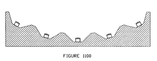
- FIG. 1100 depicts an array of Light Emitting Diodes placed in angle walled cups which are arranged in a curved shape.
- FIG. 1105 depicts an array of Light Emitting Diodes placed in angled reflective walled or curved reflective walled trenches.
- FIG. 1110 depicts an array of Light Emitting Diodes that are placed in cups as well as trenches.
- FIG. 1115 depicts a large array of Light Emitting Diodes that are placed in cups (singularly or in groups) which are electrically isolated from each other in quarters.
- FIG. 1120 depicts a less dense array of Light Emitting Diodes, in cups and electrically isolated from each other in quarters.
- FIG. 1130 depicts an array of Light Emitting Diodes comprised of 2 separate types of Light Emitting Diodes which are placed in angle or curved reflective wall trenches. Electrical isolation of the two different types of diodes as well as their electrical connection is also depicted.
- FIG. 1150 depicts a closely compacted Light Emitting Diode array placed in individual angled or curved reflective wall cups. Quartered electrical isolation is also depicted.
- FIG. 1155 depicts a less tightly compacted array of Light Emitting Diodes placed in single angled or curved reflective wall cups. Quartered electrical isolation is also depicted.
- FIG. 1160 depicts a Light Emitting Diode array placed in angled or curved reflective wall trenches. Halved electrical isolation is also depicted.
- FIG. 1165 depicts a tightly compacted array of Light Emitting Diodes placed in single angled or curved reflective wall cups with no electrical isolation.
- FIG. 1200 depicts an array of Light Emitting Diodes in reflective walled cups with an array of focusing/columniation lenses depicted.
- FIG. 1300 depicts an array of Light Emitting Diodes in reflective walled cups with a single lens providing addition focusing/columniation.
- FIG. 1400 depicts an array of focusing/columniation lenses placed over a single reflective wall cup.
- FIG. 1500 depicts an array of large focusing/columniation lenses placed over an array of Light Emitting Diodes placed in reflective walled cups.
- FIG. 1600 depicts an array of Light Emitting Diodes placed in single reflective wall cups sealed with a single optical, non-focusing/collimating window.
- FIG. 1700 depicts an assembly of a Light Emitting Diode array, a heat transfer device (heat pipe) and a heat dissipating device (heat sink).
- FIG. 1750 depicts an assembly with electrical connections where the heat transfer/heat sink assembly is also an integral electrical connection (anode).
- FIG. 1800 depicts water cooling assembly for the Light Emitting Diode array.
- FIG. 1850 depicts an assembly which first transfers the heat by way of heat pipe and then removes the heat by way of circulation water.
- FIG. 1900 depicts a machinist drawing for constructing a Light Emitting Diode array for a Light Emitting Diode dental curing light source.
- FIG. 1910 depicts a machinist drawing for constructing a Light Emitting Diode array for a Light Emitting Diode dental curing light source.
- FIG. 1920 depicts a machinist drawing for constructing a Light Emitting Diode array for a Light Emitting Diode dental curing light source.
- FIG. 1930 depicts a machinist drawing for constructing a Light Emitting Diode array for a Light Emitting Diode dental curing light source.
- FIG. 1940 depicts a machinist drawing for constructing a Light Emitting Diode array for a Light Emitting Diode dental curing light source.
- FIG. 2000 depicts a machinist drawing for constructing the heat sink (air) for a Light Emitting Diode dental curing light source.
- FIG. 2010 depicts a machinist drawing for constructing the heat sink (air) for a Light Emitting Diode dental curing light source.
- FIG. 2020 depicts a machinist drawing for constructing the heat sink (air) for a Light Emitting Diode dental curing light source.
- FIG. 2030 depicts a machinist drawing for constructing the heat sink (air) for a Light Emitting Diode dental curing light source.
- FIG. 2100 depicts and assembly drawing to assemble a Light Emitting Diode dental curing light source.
- FIG. 2110 depicts an assembly drawing to assemble a Light Emitting Diode dental curing light source.
- FIG. 2200 depicts an electrical schematic to construct a circuit which would modulate the Light Emitting Diode array of a Light Emitting Diode dental curing light source.
- FIG. 2300 depicts an electrical schematic to construct a circuit which would drive the Light Emitting Diode array of a Light Emitting Diode dental curing light source.
- FIG. 2400 depicts an electrical schematic to construct a circuit which would charge the batteries of and allow AC (plugged into the wall) operation of a Light Emitting Diode array of a Light Emitting Diode dental curing light source.
- FIG. 2500 depicts an electrical schematic to construct the AC power supply for a Light Emitting Diode array for a Light Emitting Diode dental curing light source.
- FIG. 2600 depicts an assembly drawing for the cooling layout of a Light Emitting Diode dental curing light source where the cooling is accomplished by water circulation or phase change heat effussion material.
- FIG. 2700 depicts an assembly drawing for a Light Emitting Diode dental curing light source.
- FIG. 2800 depicts and assembly drawing for a Light Emitting Diode dental curing light source.
- FIG. 2900 depicts an assembly drawing for a Light Emitting Diode light source.
- FIG. 3000 depicts an assembly drawing for a Light Emitting Diode light source.
- the invention first takes the LED as an electronic component without any lenses or wires attached, FIG. 100 .
- the LED is essentially a cube with dimensions on the order of 0.250 millimeters, FIG. 100 .
- On the top surface is an Anode ( 101 ).
- the bottom surface is metallized and serves as the Cathode and the heat transfer point/medium ( 102 ).
- the LED also contains a layer of semiconductor that is doped with specific materials in specific concentrations to produce the desired wavelength of light ( 103 ).
- the LED contains a layer of semiconductor substrate ( 104 ). When electrical current is passed between the cathode ( 102 ) and the anode ( 101 ), photons of a particular wavelength (depending on the composition of the materials) are emitted from the doped semiconductor layer ( 103 ).
- the invention places the LED or LED array on one side of a flat substrate in all configurations of the invention the substrate is both electrically and thermally conductive.
- This provides the invention with two unique and superior feature; the heat is immediately removed from the LED and the heat removing/transporting substrate becomes integral with the anode of the LED hence serving as a heat removal device and electrical connection.
- the walls of the cup ( 201 ) are manufactured such that they are on a 45 degree angle.
- FIG. 200 the walls of the cup ( 201 ) are manufactured such that they are on a 45 degree angle.
- FIG. 400 LEDs emit photons ( 401 ) in all directions.
- the invention improves the efficiency of reflection by providing additional cup designs such as a cups containing hemispheric, elliptical or parabolic curve.
- the elliptical cup ( 501 ) because of its curved surfaces reflects omnidirectional photons ( 502 ) into one directional photons ( 503 ).
- FIG. 600 by adjusting the altitude of the LED within the ellipse ( 601 ) the invention allows for the omnidirectional photons ( 602 ) to be reflected to a specific, predetermine, focal point in space ( 603 ).
- the invention allows the majority of photons produced by the LED to be placed at a specific point in space where they are needed. Additional cup designs that are useful to the invention (with or without the lenses illustrated) are illustrated in FIGS. 625 , 650 , and 675 .
- the specific examples of cup design listed above are not intended to be restrictive to the invention in any way, for instance, a pyramidal (upside down) design as been suggested. The descriptions are simply given to illustrate the potential of specific cup designs. The actual design of the cups would be varied and specific to the application.
- the invention assembles many LEDs into arrays in order to achieve higher optical output powers than are achieved with a single LED.
- FIG. 800 the invention provides for single LEDs placed in a many cup array.
- the invention is not restricted to this configuration.
- FIG. 900 in the invention the array can be accomplished by placing a number of LEDs within the same cup.
- the invention also utilized an array of LEDs in each cup coupled with and array of cups, FIG. 1000 .
- FIG. 1000 there are 4 single LEDs per cup and an array of 16 cups in a circular pattern.
- the invention is not limited to circular pattern arrays ( 1000 ) and square pattern arrays ( 800 ), indeed, the pattern of the array is only limited to the potential application.
- the description of single LEDs in a cup ( 800 ) or an array of 4 LEDs in a cup ( 900 ) is not meant to restrict the invention to these two descriptions, again, the number of LEDs arrayed per cup is only limited by the application to which it is intended. It is also useful to the invention to manufacture various shapes into which the cups are machined or stamped, FIG. 1100 . In this configuration ( 1100 ) the invention takes advantage of the light reflecting design of the cup and further enhance these properties by positioning the cups themselves in a dish shaped plate.
- FIGS. 1125 and 1150 illustrate additional arrays and ‘cup’ configurations that are useful to the; invention.
- FIG. 1125 illustrates array configuration in which many LEDs can be placed in arrays that are approximately 1 ⁇ 2 inch in diameter.
- 1126 , 1127 , and 1128 are illustrations of cup designs that are in a ‘trench’ format, where the sides of the trench are designed in an angled or curved shape.
- 1150 illustrates array configurations win which many LEDs can be placed in arrays that are approximately 1.5 inches in diameter.
- 1151 utilizes the trench rather than individual cup design. Again these examples are not meant to be restrictive. They are meant to illustrate some of the many potential array/cup designs that are useful to the invention.
- the invention makes use of single lenses, including but not limited to Graded Index of Refraction (GRIN) lenses, lens arrays, including but not limited to Graded Index of Refraction (GRIN) lenses and holographic films, including but not limited to Graded Index of Refraction (GRIN) lenses in order to further process the light and deliver it, in its most useful quantities and qualities, to the specific applications.
- FIGS. 625 , 650 , 675 , and 1200 the invention provides for the use of miniature lenses or holographic films ( 1201 ) placed directly over the individual cups ( 1202 ) forming an array of lenses or holographic films.
- the invention also allows for the use of a single lens or holographic film ( 1301 ) to be placed over the entire array of cups ( 1302 ).
- FIG. 1400 it is also useful to the invention to provide an array of lenses or holographic films ( 1401 ).
- the array of lenses or holographic films could contain many lenses, many films or a combination of lenses and films.
- FIG. 1500 it is useful to the invention to place these arrays over a single cup as illustrated in FIG. 1400 but it is also useful to the invention, FIG. 1500 , to place a place an array of lenses ( 1501 ) and/or holographic film(s) over an array of cups ( 1502 ).
- FIG. 1600 an appropriate sized piece of anti-reflective (AR) coated optical glass ( 1601 ) is placed over the array ( 1602 ) and secured with ultraviolet light cured optical adhesive ( 1603 ) thus protecting the LEDs from adverse environmental conditions.
- AR anti-reflective
- FIG. 1600 an appropriate sized piece of anti-reflective (AR) coated optical glass ( 1601 ) is placed over the array ( 1602 ) and secured with ultraviolet light cured optical adhesive ( 1603 ) thus protecting the LEDs from adverse environmental conditions.
- AR anti-reflective
- the discussion and examples listed by way of lenses, holographic films and sealing windows (optical glass) are not intended to restrict the invention to the described scenarios but is rather to illustrate some of the many potential configurations that are useful to the invention. For instances, it has been suggested that micro ball lenses could be used for particular applications. The configuration of lenses, holographic films and sealing optics are only limited to the dictation's of the particular application.
- the invention facilitates the removal thermal energy from single LEDs in a flat mounted configuration or in a single cup or from arrays of cups with single LEDs or from arrays of cups that individually contain arrays of LEDs while it maintains electrical insulation and conductivity where appropriate.
- Cup is defined in the context of this patent as a “shaped hole” in which a single LED or a number of LEDs can be placed.
- the word cup refers to any configuration that could accept an LED or LEDs.
- FIGS. 1120 and 1115 illustrate cups that are circular while FIGS. 1105 , 1110 and 1130 illustrate cups that are formed in a ‘trench’ configuration.
- the cup housing may be manufactured from a thermally and electrically conductive material (substrate) such as copper and is plated with optically reflective, thermally conductive and electrically conductive material such as first nickel and then rhodium, or silver ( 1701 ).
- the LED(s) then may be secured to the bottom of the cup(s) using a thermally and electrically conductive adhesive such as silver filled epoxy ( 1702 ).
- the separate sections of LED/cups ( 1703 ) are then bonded to a plate made of heat conducting material (substrate) such as aluminum or copper ( 1710 ) with a space between the cup sections ( 1704 ) to provide electrical isolation. They are bonded to the plate using a thermally conductive but electrically insulating adhesive such as Thermal Epoxy, Electrically Insulating ( 1705 ).
- the LED(s) are then electrically connected by soldiering or conductively bonding the gold wires to the contacts ( 1706 ) and connecting them in series to the next electrically isolated cup(s) ( 1707 ).
- a gold wire is then soldiered or bonded to the contact of the last LED(s) ( 1708 ) in the series and is taken out to connect to the positive side of the direct current power source ( 1709 ).
- a gold wire is then soldiered or bonded to the cup material of the first LED(s) ( 1711 ) in the series and directed toward the negative side of the direct current power source ( 1712 ).
- Optical adhesive such as Ultra-Violet Activated Optical Adhesive is placed around the tops of the cups ( 1713 ), the gold wire leaving the last in the series of LED(s) is then embedded in the optical adhesive ( 1714 ) to provide electrical insulation.
- the optical window (or lenses, holographic films or arrays of lenses and/or holographic films and/or optical windows) ( 1715 ) is then position and set into the optical adhesive ( 1713 ) and the optical adhesive is cured with an ultra-violet light source.
- This assembly is then soldiered or bonded (using a thermally conductive adhesive) ( 1716 ) to a heat pipe ( 1717 ).
- the heat pipe is then soldiered or bonded to a heat sink ( 1718 ) manufactured from a thermally conductive material designed to dissipate heat in to a heat dissipation environment such as aluminum or copper.
- the heat dissipation environment is an environment that conducts the heat away from the heat sink such as air, water, phase change heat effusion material or a combination of air, water, and phase change heat effusion material.
- the heat sink is then secured to a chamber ( 1719 ) which houses either the direct current power supply, batteries to supply direct current or facilitates connection to an outside direct current power supply.
- This chamber is then connected to a fan (to move air, water and or phase change heat effusion material ( 1720 ) if additional cooling is requisite for the application.
- FIG. 1000 illustrates such a scenario or configuration.
- FIG. 1000 there are 4 sections which contain 4 cups each.
- Each cup contains 4 LEDs.
- the negative side of a direct current power source would be attached to one of the sections of cup material.
- the electrical connectors of each of the sixteen LEDs in this first section would have gold wires soldiered to them and each of these wire would then be soldiered to the next, or second, section of the cup material.
- the electrical connectors of each of the sixteen LEDs in this second section would have gold wires soldiered to them and each of these wires would then be soldiered to the next (third) section of the cup material.
- the electrical connectors of each of the sixteen LEDs in the third section would have gold wires soldiered to them and each of these wire would then be soldiered to the next (forth) section of the cup material.
- the electrical connectors of each of the sixteen LEDs in the forth section would have gold wires soldiered to them and each of these wire would then be directed to the positive side of the direct current power source. In effect and actually this would produce a series circuit which contains 4 series of 16 LEDs wired in parallel.
- the substrate used to manufacture the cups ( 1703 ) may be made of the same material used to manufacture the substrate for heat removal ( 1710 ) making it an integral one piece assembly, refer to FIGS. 1910 , 1920 , 1930 and 1940 .
- the substrate is an integral heat sink. Electrical isolation is accomplished by bonding a copper conductive sheet using non-conductive epoxy to the top surface of the substrate and wire bonding the LEDs' cathodes to the copper conductive sheet, refer to FIG. 1930 .
- the substrate conducts heat away from the LEDs while conducting electrical current to the anode, electrical current is supplied to the cathode by way of a sheet of copper that has been secured with non-conductive epoxy to the top of the substrate.
- FIG. 1910 , 1920 , 1930 and 1940 the substrate is an integral heat sink. Electrical isolation is accomplished by bonding a copper conductive sheet using non-conductive epoxy to the top surface of the substrate and wire bonding the LEDs' cathodes to the copper conductive sheet, refer to FIG. 1930 .
- the substrate conducts heat away from
- 1130 incorporates two electrical circuits ( 1133 , 1135 ) which are electrically isolated by machined paths ( 1134 , 1131 ). This allows two separate types of LEDs (for instance 430 nanometer and 450 nanometer) to be incorporated into the same curing device. This design is incorporated into the proto-type that was constructed and tested and is the subject of the example below.
- FIG. 1800 Another configuration useful to the invention would eliminate the heat pipe and provide a heat dissipation environment directly in the substrate.
- 1801 is a heat dissipation environment chamber which allows the heat dissipation environment material (air, water, phase change heat effusion material, or combination thereof) to simple absorb the heat while being stored in the chamber or may be circulated through the chamber between port ( 1802 , 1803 ).
- the substrates in this configuration can be separated as depicted or may be integral, made of the same material with no separation, providing heat removal, heat dissipation and integral anodic electrical connection.
- Yet another useful configuration would be to add the heat pipe, refer to FIG.
- heat dissipation environment chamber ( 1850 ) to move the ‘bulky’ heat dissipation environment chamber away from the slender, light weight, array assembly.
- heat is immediately transferred from the LEDs through the substrate ( 1851 ) (either separated or integral as discussed above), through the heat pipe ( 1852 ) and into the heat dissipation environment chamber ( 1853 ).
- the heat dissipation environment chamber ( 1853 ) which allows the heat dissipation environment material (air, water, phase change heat effusion material, or combination thereof) to simply absorb the heat while being stored in the chamber or may be circulated through the chamber between port ( 1854 , 1855 ).
- FIGS. 625 , 650 , and 675 Illustrate such a configuration.
- 626 , 651 , and 676 represent an thin film of electrically insulating material
- 627 , 652 , and 677 represent a layer of electrically conductive material such as copper, or copper plated with gold
- 628 , 653 , and 678 represent the wire that would attach the LEDs' anode to the electrically conductive layer.
- the cathode ( 629 , 654 , and 679 ) is then bonded directly to the heat sink material/configuration ( 630 , 655 , and 680 ) utilizing heat and electrically conductive adhesive producing a unique integral anode heat sink configuration.
- the circuits are then separated, where necessary, on the top electrically conductive layer ( 627 , 652 , and 677 ).
- FIG. 1128 illustrates ‘trenches’ ( 1131 and 1134 ) cut through the electrically conductive layer ( 627 , 652 , and 677 ) into the electrically insulating material ( 626 , 651 , and 676 ).
- This configuration ( 1130 ) effectively produces two, electrically separated circuits ( 1133 and 1135 ).
- This configuration allows to wire approximately 1 ⁇ 2 of the LEDs in parallel with each other and the other half of the LEDs in parallel with each other and then wire the halves in series, enabling the designer to manage voltage and current. It also allows the designer to operate two different types of LEDs that have different wavelength output and would require different currents and voltages to drive them optimally.
- FIGS. 2100 and 2110 using DM6030HK-SD/H569 Silver Filled Epoxy Paste (Diemat, Inc., Topsfield, Mass.). Attach the LED array assembly completed by LDX Optronix to the other end of the heat pipe as illustrated in FIGS. 2100 and 2110 .
- a machine shop such as Axis Machine construct a housing out of a plastic material in accordance with the illustration in FIGS. 2100 and 2110 .
- Have a company such a KWM Electronics Corp., West Jordan, Utah manufacture 4 printed circuit according to the schematic specification in FIGS. 2200 , 2300 , 2400 and 2500 . Install the circuits created from FIGS. 2200 and 2300 into the handle ( 2101 and 2102 respectively) as illustrated in FIG. 2100 .
- FIG. 2100 Further install the circuit created from FIG. 2400 into the battery compartment ( 2103 ) as illustrated in FIG. 2100 .
- the final circuit is mounted in a small kit box available from any Radio Shack, Nationalwide. At household 120 volt AC input cord is installed and an output cord with the corresponding jack on the circuit produced by FIG. 2400 is also installed such that the output cord from the External Power Supply Assembly will plug into the circuit created by FIG. 2400 which is installed in the battery compartment.
- This enables the batteries to be recharged or the light to be operated off of household 120 volt AC while the batteries are being recharged.
- the device does not necessarily have to have a fan. It could be run with natural air convection providing the cooling, water or a phase change heat effusion material such as sodium Sulfate Decahydrate, Aldrich Chemical Co., Milwaukee, Wis. In such a configuration the solid Sodium Sulfate Decahydrate would absorb the heat from the heat pipe and/or heat sink. As it absorbs the heat it converts from a solid to a liquid (phase change) storing the heat.
- a phase change heat effusion material such as sodium Sulfate Decahydrate, Aldrich Chemical Co., Milwaukee, Wis.
- the heat could then be removed by convection or by way of a mechanical linkage, possibly in a ‘recharge station’ which would convert the sodium Sulfate Decahydrate to a solid form again.
- a mechanical linkage possibly in a ‘recharge station’ which would convert the sodium Sulfate Decahydrate to a solid form again.
- Using any number of phase change hear effusion materials is very useful to the invention in that it eliminates the need for a fan which places additional current demand on the batteries and circuitry, it also adds the noise of the fan to the environment where the light is used.
- water could even be stored in the chamber ( 2115 ) and re-circulated through the heat sink compartment, making the heat sink compartment and chamber 2115 the entire heat dissipation environment.
- the water could be simply be pumped through the environment and discarded through an input and output port constructed in the chamber as well.
- the basic concepts, designs, and circuitry of this example are not strictly limited to the design of placing the LED array in the immediate vicinity of the tooth.
- the LED array is placed in the main housing and the light is delivered by fiber optic or light guide as illustrated in FIG. 2600 .
- the LED array ( 2602 ) is mounted to the end of a heat pipe ( 2606 ) which is then attached to a heat sink ( 2605 ), the heat sink being integrated also as the anode for the LEDs as described earlier.
- the Led Array ( 2602 ) produces light which passes through a lens, lens array or halographic film as discussed earlier.
- the light then passes into the light delivery device ( 2604 ) which could be a rigid light guide as portrayed in FIG. 2600 or could be a single fiber or a bundle of fibers.
- the fan compartment ( 2601 ) could be filled with water, a phase change heat effusion material as illustrated in FIG. 2600 and discussed earlier or it could contain a fan for cooling.
- FIG. 2700 illustrates another potential ‘pistol’ type design which incorporates the LED array close to the working surface
- FIG. 2800 illustrates another potential ‘pistol’ type design which incorporates the LED array within the housing utilizing a light delivery device to get the light to the work surface.
- FIG. 2900 illustrates a ‘pistol’ type device that contains an LED array ( 2901 ) approximately 3 times the diameter of the example, which would contain approximately 5 times as many LEDs in the array.
- the LED array uses an integral anode/heat sink configuration where the heat sink ( 2903 ) may or may not include a heat pipe ( 2902 ). It contains a cooling compartment ( 2904 ) which could house a fan, nothing at all, water, or a phase change heat effusion material or a combination thereof.
- the heat dissipation environment could be stagnant or circulating.
- a device such as the one illustrated in 2900 could designed for use as a dental curing light, dental bleach activator, forensic light source to name but a few.
- FIG. 3000 illustrates the ability of the concepts to be incorporated in a ‘flashlight’ design which contains all of the basic elements of the invention: an LED array ( 3001 ), with or without a lens, lens array, halographic film, light delivery device or combination thereof, a heat sink ( 3003 ) which could or could not also be the anode, the heat sink may or may not incorporate a heat pipe ( 3003 ), the housing includes a space for electronic ( 3005 ), batteries ( 3005 ), and a cooling compartment ( 3007 ).
Abstract
Description
Claims (41)
Priority Applications (1)
| Application Number | Priority Date | Filing Date | Title |
|---|---|---|---|
| US11/061,083 US7789661B2 (en) | 2000-03-08 | 2005-02-18 | Light emitting diode light source |
Applications Claiming Priority (3)
| Application Number | Priority Date | Filing Date | Title |
|---|---|---|---|
| US18789900P | 2000-03-08 | 2000-03-08 | |
| US09/801,351 US7320593B2 (en) | 2000-03-08 | 2001-03-07 | Light emitting diode light source for curing dental composites |
| US11/061,083 US7789661B2 (en) | 2000-03-08 | 2005-02-18 | Light emitting diode light source |
Related Parent Applications (1)
| Application Number | Title | Priority Date | Filing Date |
|---|---|---|---|
| US09/801,351 Continuation US7320593B2 (en) | 2000-03-08 | 2001-03-07 | Light emitting diode light source for curing dental composites |
Publications (2)
| Publication Number | Publication Date |
|---|---|
| US20050196720A1 US20050196720A1 (en) | 2005-09-08 |
| US7789661B2 true US7789661B2 (en) | 2010-09-07 |
Family
ID=26883522
Family Applications (2)
| Application Number | Title | Priority Date | Filing Date |
|---|---|---|---|
| US09/801,351 Expired - Fee Related US7320593B2 (en) | 2000-03-08 | 2001-03-07 | Light emitting diode light source for curing dental composites |
| US11/061,083 Expired - Fee Related US7789661B2 (en) | 2000-03-08 | 2005-02-18 | Light emitting diode light source |
Family Applications Before (1)
| Application Number | Title | Priority Date | Filing Date |
|---|---|---|---|
| US09/801,351 Expired - Fee Related US7320593B2 (en) | 2000-03-08 | 2001-03-07 | Light emitting diode light source for curing dental composites |
Country Status (1)
| Country | Link |
|---|---|
| US (2) | US7320593B2 (en) |
Cited By (13)
| Publication number | Priority date | Publication date | Assignee | Title |
|---|---|---|---|---|
| US20080268401A1 (en) * | 2005-04-08 | 2008-10-30 | Invisitech Co., Ltd. | Led Having Wide Wavelength-Range and Light Curing Unit Using the Same |
| US7989839B2 (en) | 2002-08-23 | 2011-08-02 | Koninklijke Philips Electronics, N.V. | Method and apparatus for using light emitting diodes |
| US20110255278A1 (en) * | 2009-06-24 | 2011-10-20 | Mahendra Dassanayake | Solid state light assembly having light redirection elements |
| US20130049011A1 (en) * | 2007-08-02 | 2013-02-28 | Cree, Inc. | Optoelectronic device with upconverting luminophoric medium |
| US20140218943A1 (en) * | 2013-02-01 | 2014-08-07 | Crystalplex Corporation | Aluminum printed circuit board for lighting and display backplanes |
| USD740471S1 (en) * | 2014-05-16 | 2015-10-06 | Ningbo Yinzhou Self Photoelectron Technology Co., Ltd. | Lighthead |
| USD740999S1 (en) * | 2014-05-16 | 2015-10-13 | Ningbo Yinzhou Self Photoelectron Technology Co., Ltd. | Lighthead lens |
| USD810293S1 (en) | 2017-01-20 | 2018-02-13 | Garrison Dental Solutions, Llc | Dental instrument |
| US9931187B2 (en) | 2012-04-05 | 2018-04-03 | Brad HECKERMAN | Photon induced acoustic streaming device and method |
| US10132484B2 (en) | 2005-05-02 | 2018-11-20 | Kavo Dental Technologies, Llc | LED-based dental exam lamp |
| US10159548B2 (en) | 2014-09-17 | 2018-12-25 | Garrison Dental Solutions, L.L.C. | Dental curing light |
| WO2019161410A1 (en) * | 2018-02-19 | 2019-08-22 | Millennium Healthcare Technologies, Inc. | Dental lasing device system and method |
| US10539297B2 (en) | 2011-06-20 | 2020-01-21 | Crystalplex Corporation | Quantum dot containing light module |
Families Citing this family (156)
| Publication number | Priority date | Publication date | Assignee | Title |
|---|---|---|---|---|
| US6517532B1 (en) | 1997-05-15 | 2003-02-11 | Palomar Medical Technologies, Inc. | Light energy delivery head |
| US8182473B2 (en) | 1999-01-08 | 2012-05-22 | Palomar Medical Technologies | Cooling system for a photocosmetic device |
| US6273884B1 (en) | 1997-05-15 | 2001-08-14 | Palomar Medical Technologies, Inc. | Method and apparatus for dermatology treatment |
| GB2329756A (en) | 1997-09-25 | 1999-03-31 | Univ Bristol | Assemblies of light emitting diodes |
| US6200134B1 (en) | 1998-01-20 | 2001-03-13 | Kerr Corporation | Apparatus and method for curing materials with radiation |
| EP1566149A1 (en) | 1998-03-12 | 2005-08-24 | Palomar Medical Technologies, Inc. | System for electromagnetic radiation of the skin |
| US7294364B2 (en) * | 1999-09-24 | 2007-11-13 | Cao Group, Inc. | Method for curing composite materials |
| US7001057B2 (en) * | 2001-05-23 | 2006-02-21 | Ivoclar Vivadent A.G. | Lighting apparatus for guiding light onto a light polymerizable piece to effect hardening thereof |
| US6692252B2 (en) | 2001-12-17 | 2004-02-17 | Ultradent Products, Inc. | Heat sink with geometric arrangement of LED surfaces |
| CA2474455A1 (en) * | 2002-01-30 | 2003-08-21 | Societe Pour La Conception Des Applications Des Techniques Electroniques - Satelec | Electro-optical device for the photo-polymerization of composite material |
| US6702576B2 (en) | 2002-02-22 | 2004-03-09 | Ultradent Products, Inc. | Light-curing device with detachably interconnecting light applicator |
| US6843967B2 (en) * | 2002-04-11 | 2005-01-18 | Pentron Laboratory Technologies, Llc | Curing unit |
| EP1508157B1 (en) | 2002-05-08 | 2011-11-23 | Phoseon Technology, Inc. | High efficiency solid-state light source and methods of use and manufacture |
| WO2006072071A2 (en) | 2004-12-30 | 2006-07-06 | Phoseon Technology Inc. | Methods and systems relating to light sources for use in industrial processes |
| DE10222828B4 (en) * | 2002-05-21 | 2008-05-15 | 3M Espe Ag | irradiator |
| US7135033B2 (en) | 2002-05-23 | 2006-11-14 | Palomar Medical Technologies, Inc. | Phototreatment device for use with coolants and topical substances |
| USRE47011E1 (en) * | 2002-05-29 | 2018-08-28 | Optolum, Inc. | Light emitting diode light source |
| US6573536B1 (en) * | 2002-05-29 | 2003-06-03 | Optolum, Inc. | Light emitting diode light source |
| BR0312430A (en) | 2002-06-19 | 2005-04-26 | Palomar Medical Tech Inc | Method and apparatus for treating skin and subcutaneous conditions |
| ATE527119T1 (en) * | 2002-07-01 | 2011-10-15 | Inca Digital Printers Ltd | PRESSURE APPARATUS AND METHOD |
| GB2396331A (en) * | 2002-12-20 | 2004-06-23 | Inca Digital Printers Ltd | Curing ink |
| AU2003265308A1 (en) | 2002-07-25 | 2004-02-16 | Jonathan S. Dahm | Method and apparatus for using light emitting diodes for curing |
| US7182597B2 (en) * | 2002-08-08 | 2007-02-27 | Kerr Corporation | Curing light instrument |
| US6880954B2 (en) | 2002-11-08 | 2005-04-19 | Smd Software, Inc. | High intensity photocuring system |
| US7465909B2 (en) * | 2003-01-09 | 2008-12-16 | Con-Trol-Cure, Inc. | UV LED control loop and controller for causing emitting UV light at a much greater intensity for UV curing |
| US7671346B2 (en) * | 2003-01-09 | 2010-03-02 | Con-Trol-Cure, Inc. | Light emitting apparatus and method for curing inks, coatings and adhesives |
| US20040164325A1 (en) * | 2003-01-09 | 2004-08-26 | Con-Trol-Cure, Inc. | UV curing for ink jet printer |
| US20050042390A1 (en) * | 2003-01-09 | 2005-02-24 | Siegel Stephen B. | Rotary UV curing method and apparatus |
| US20060121208A1 (en) * | 2003-01-09 | 2006-06-08 | Siegel Stephen B | Multiple wavelength UV curing |
| US7399982B2 (en) * | 2003-01-09 | 2008-07-15 | Con-Trol-Cure, Inc | UV curing system and process with increased light intensity |
| US7137696B2 (en) * | 2003-01-09 | 2006-11-21 | Con-Trol-Cure, Inc. | Ink jet UV curing |
| US20060204670A1 (en) * | 2003-01-09 | 2006-09-14 | Con-Trol-Cure, Inc. | UV curing method and apparatus |
| US7211299B2 (en) * | 2003-01-09 | 2007-05-01 | Con-Trol-Cure, Inc. | UV curing method and apparatus |
| US7175712B2 (en) * | 2003-01-09 | 2007-02-13 | Con-Trol-Cure, Inc. | Light emitting apparatus and method for curing inks, coatings and adhesives |
| US7498065B2 (en) * | 2003-01-09 | 2009-03-03 | Con-Trol-Cure, Inc. | UV printing and curing of CDs, DVDs, Golf Balls And Other Products |
| US7493409B2 (en) * | 2003-04-10 | 2009-02-17 | International Business Machines Corporation | Apparatus, system and method for implementing a generalized queue pair in a system area network |
| US20060141422A1 (en) * | 2004-04-20 | 2006-06-29 | K Philp Graham Jr | Method and apparatus for tooth whitening |
| US7675075B2 (en) | 2003-08-28 | 2010-03-09 | Panasonic Corporation | Semiconductor light emitting device, light emitting module, lighting apparatus, display element and manufacturing method of semiconductor light emitting device |
| WO2005041632A2 (en) | 2003-10-31 | 2005-05-12 | Phoseon Technology, Inc. | Collection optics for led array with offset hemispherical or faceted surfaces |
| EP1706432A4 (en) * | 2004-01-23 | 2008-09-03 | Con Trol Cure Inc | Light emitting apparatus and method for curing inks, coatings and adhesives |
| TWI257718B (en) * | 2004-03-18 | 2006-07-01 | Phoseon Technology Inc | Direct cooling of LEDs |
| US7638808B2 (en) * | 2004-03-18 | 2009-12-29 | Phoseon Technology, Inc. | Micro-reflectors on a substrate for high-density LED array |
| EP1743384B1 (en) * | 2004-03-30 | 2015-08-05 | Phoseon Technology, Inc. | Led array having array-based led detectors |
| WO2005101535A2 (en) * | 2004-04-12 | 2005-10-27 | Phoseon Technology, Inc. | High density led array |
| WO2005100408A1 (en) * | 2004-04-15 | 2005-10-27 | Ciba Specialty Chemicals Holding Inc. | Process for photocuring with light emitting diodes |
| EP1738156A4 (en) | 2004-04-19 | 2017-09-27 | Phoseon Technology, Inc. | Imaging semiconductor strucutures using solid state illumination |
| US20060018123A1 (en) * | 2004-07-02 | 2006-01-26 | Rose Eric P | Curing light having a reflector |
| CN101014295A (en) * | 2004-07-02 | 2007-08-08 | 底斯柯斯牙齿印模公司 | Curing light device having a reflector |
| US8025502B2 (en) * | 2004-07-02 | 2011-09-27 | Discus Dental, Llc | Light guide for dentistry applications |
| MXPA06014977A (en) * | 2004-07-02 | 2007-03-27 | Discus Dental Impressions Inc | Dental light device having an improved heat sink. |
| US20080032252A1 (en) * | 2004-08-25 | 2008-02-07 | Discus Dental Impressions, Llc | Illumination system for dental applications |
| US20060162365A1 (en) * | 2004-10-26 | 2006-07-27 | Hoang Triem T | Cooling electronics via two-phase tangential jet impingement in a semi-toroidal channel |
| US7331691B2 (en) * | 2004-10-29 | 2008-02-19 | Goldeneye, Inc. | Light emitting diode light source with heat transfer means |
| AU2005314712A1 (en) * | 2004-12-09 | 2006-06-15 | Palomar Medical Technologies, Inc. | Oral appliance with heat transfer mechanism |
| DE102005003802A1 (en) * | 2004-12-10 | 2006-06-14 | Nütro Maschinen- und Anlagenbau GmbH & Co. KG | Radiation apparatus and powder application station and arrangement for coating temperature-sensitive materials and method thereof |
| CA2592055A1 (en) * | 2004-12-27 | 2006-07-06 | Quantum Paper, Inc. | Addressable and printable emissive display |
| EP1846949B1 (en) * | 2005-01-05 | 2018-08-22 | Philips Lighting Holding B.V. | Thermally and electrically conductive apparatus |
| WO2006105638A1 (en) * | 2005-04-05 | 2006-10-12 | Tir Systems Ltd. | Electronic device package with an integrated evaporator |
| US7856985B2 (en) | 2005-04-22 | 2010-12-28 | Cynosure, Inc. | Method of treatment body tissue using a non-uniform laser beam |
| US9566140B2 (en) | 2005-04-27 | 2017-02-14 | Dentovations Inc. | Method and device for whitening teeth using sonochemistry |
| US7210814B2 (en) | 2005-04-29 | 2007-05-01 | Ultradent Products, Inc. | Dental curing light with specially arranged LEDs |
| US20080025013A1 (en) * | 2005-05-02 | 2008-01-31 | Pelton & Crane | Led-powered dental operatory light |
| US8016470B2 (en) | 2007-10-05 | 2011-09-13 | Dental Equipment, Llc | LED-based dental exam lamp with variable chromaticity |
| US8113830B2 (en) | 2005-05-27 | 2012-02-14 | Kerr Corporation | Curing light instrument |
| US7490967B2 (en) * | 2005-06-15 | 2009-02-17 | Philip Syribeys | Solid state light source including cooling system |
| JP2009509140A (en) | 2005-09-15 | 2009-03-05 | パロマー・メデイカル・テクノロジーズ・インコーポレーテツド | Skin optical determination device |
| GB0524909D0 (en) * | 2005-12-06 | 2006-01-11 | Enfis Ltd | Improved LED array |
| US7642527B2 (en) | 2005-12-30 | 2010-01-05 | Phoseon Technology, Inc. | Multi-attribute light effects for use in curing and other applications involving photoreactions and processing |
| US7892268B2 (en) * | 2006-03-23 | 2011-02-22 | Light Sciences Oncology, Inc. | PDT apparatus with high output LED for therapy and aiming |
| US7586957B2 (en) | 2006-08-02 | 2009-09-08 | Cynosure, Inc | Picosecond laser apparatus and methods for its operation and use |
| KR100837371B1 (en) * | 2006-08-03 | 2008-06-12 | 컨트롤 큐어, 인코포레이티드 | Light emitting apparatus and method for curing inks, coatings and adhesives |
| DE102006036828B3 (en) * | 2006-08-07 | 2008-04-17 | Ivoclar Vivadent Ag | light curing |
| US8047686B2 (en) | 2006-09-01 | 2011-11-01 | Dahm Jonathan S | Multiple light-emitting element heat pipe assembly |
| US20080101073A1 (en) * | 2006-11-01 | 2008-05-01 | Discus Dental, Llc | Dental Light Devices Having an Improved Heat Sink |
| US20080166678A1 (en) * | 2007-01-04 | 2008-07-10 | Or Ramot | Removable intraoral lighting device |
| US7837369B2 (en) * | 2007-01-22 | 2010-11-23 | Seiko Epson Corporation | Light-emitting device, image-printing device, and manufacturing method of sealing member |
| PT103654B (en) * | 2007-02-07 | 2009-04-30 | Fernando Antonio Cepeda Costa | ILLUMINATING APPARATUS FOR SURGICAL INSTRUMENTS |
| US8115213B2 (en) | 2007-02-08 | 2012-02-14 | Phoseon Technology, Inc. | Semiconductor light sources, systems, and methods |
| EP1959183A1 (en) * | 2007-02-19 | 2008-08-20 | Per Aarsleff A/S | An apparatus and a method for curing a liner of a pipeline |
| US9419179B2 (en) | 2007-05-31 | 2016-08-16 | Nthdegree Technologies Worldwide Inc | Diode for a printable composition |
| US9343593B2 (en) | 2007-05-31 | 2016-05-17 | Nthdegree Technologies Worldwide Inc | Printable composition of a liquid or gel suspension of diodes |
| US8133768B2 (en) * | 2007-05-31 | 2012-03-13 | Nthdegree Technologies Worldwide Inc | Method of manufacturing a light emitting, photovoltaic or other electronic apparatus and system |
| US7972031B2 (en) * | 2007-05-31 | 2011-07-05 | Nthdegree Technologies Worldwide Inc | Addressable or static light emitting or electronic apparatus |
| US8809126B2 (en) | 2007-05-31 | 2014-08-19 | Nthdegree Technologies Worldwide Inc | Printable composition of a liquid or gel suspension of diodes |
| US8889216B2 (en) * | 2007-05-31 | 2014-11-18 | Nthdegree Technologies Worldwide Inc | Method of manufacturing addressable and static electronic displays |
| US9425357B2 (en) | 2007-05-31 | 2016-08-23 | Nthdegree Technologies Worldwide Inc. | Diode for a printable composition |
| US9018833B2 (en) | 2007-05-31 | 2015-04-28 | Nthdegree Technologies Worldwide Inc | Apparatus with light emitting or absorbing diodes |
| US8852467B2 (en) | 2007-05-31 | 2014-10-07 | Nthdegree Technologies Worldwide Inc | Method of manufacturing a printable composition of a liquid or gel suspension of diodes |
| US9534772B2 (en) | 2007-05-31 | 2017-01-03 | Nthdegree Technologies Worldwide Inc | Apparatus with light emitting diodes |
| US8846457B2 (en) | 2007-05-31 | 2014-09-30 | Nthdegree Technologies Worldwide Inc | Printable composition of a liquid or gel suspension of diodes |
| US8456393B2 (en) | 2007-05-31 | 2013-06-04 | Nthdegree Technologies Worldwide Inc | Method of manufacturing a light emitting, photovoltaic or other electronic apparatus and system |
| US8674593B2 (en) | 2007-05-31 | 2014-03-18 | Nthdegree Technologies Worldwide Inc | Diode for a printable composition |
| US8415879B2 (en) | 2007-05-31 | 2013-04-09 | Nthdegree Technologies Worldwide Inc | Diode for a printable composition |
| US8877101B2 (en) | 2007-05-31 | 2014-11-04 | Nthdegree Technologies Worldwide Inc | Method of manufacturing a light emitting, power generating or other electronic apparatus |
| US7802910B2 (en) | 2008-01-29 | 2010-09-28 | Dymax Corporation | Light guide exposure device |
| US20090208894A1 (en) * | 2008-02-18 | 2009-08-20 | Discus Dental, Llc | Curing Light |
| US9102857B2 (en) * | 2008-03-02 | 2015-08-11 | Lumenetix, Inc. | Methods of selecting one or more phase change materials to match a working temperature of a light-emitting diode to be cooled |
| US7810965B2 (en) | 2008-03-02 | 2010-10-12 | Lumenetix, Inc. | Heat removal system and method for light emitting diode lighting apparatus |
| DE102008033556A1 (en) * | 2008-03-14 | 2009-09-17 | Kaltenbach & Voigt Gmbh | Light source for a dental device |
| US7992332B2 (en) | 2008-05-13 | 2011-08-09 | Nthdegree Technologies Worldwide Inc. | Apparatuses for providing power for illumination of a display object |
| US8127477B2 (en) | 2008-05-13 | 2012-03-06 | Nthdegree Technologies Worldwide Inc | Illuminating display systems |
| US20100075272A1 (en) * | 2008-09-25 | 2010-03-25 | Chun-Ta Lin | Hand held apparatus for curing materials |
| CN101889353A (en) * | 2008-09-28 | 2010-11-17 | 张义辉 | An alternating current of led module |
| WO2010077132A1 (en) | 2008-12-31 | 2010-07-08 | Draka Comteq B.V. | Uvled apparatus for curing glass-fiber coatings |
| US7969075B2 (en) | 2009-02-10 | 2011-06-28 | Lumenetix, Inc. | Thermal storage system using encapsulated phase change materials in LED lamps |
| US9066777B2 (en) | 2009-04-02 | 2015-06-30 | Kerr Corporation | Curing light device |
| US9072572B2 (en) | 2009-04-02 | 2015-07-07 | Kerr Corporation | Dental light device |
| US8653737B2 (en) * | 2009-04-14 | 2014-02-18 | Phoseon Technology, Inc. | Controller for semiconductor lighting device |
| US8678612B2 (en) * | 2009-04-14 | 2014-03-25 | Phoseon Technology, Inc. | Modular light source |
| US9919168B2 (en) | 2009-07-23 | 2018-03-20 | Palomar Medical Technologies, Inc. | Method for improvement of cellulite appearance |
| US20110057557A1 (en) * | 2009-09-08 | 2011-03-10 | Hong Kong Applied Science And Technology Research Institute Co. Ltd. | Projection led module and method of making a projection led module |
| USD638944S1 (en) | 2009-09-22 | 2011-05-31 | Ultradent Products, Inc. | Dental illumination device |
| US20110116262A1 (en) * | 2009-11-13 | 2011-05-19 | Phoseon Technology, Inc. | Economical partially collimating reflective micro optical array |
| US9200792B2 (en) * | 2009-11-24 | 2015-12-01 | Streamlight, Inc. | Portable light having a heat dissipater with an integral cooling device |
| ES2648041T3 (en) * | 2009-12-10 | 2017-12-28 | Ivoclar Vivadent Ag | Photopolymerization device for dental purposes |
| US8465172B2 (en) * | 2009-12-17 | 2013-06-18 | Phoseon Technology, Inc. | Lighting module with diffractive optical element |
| US8123389B2 (en) * | 2010-02-12 | 2012-02-28 | Lumenetix, Inc. | LED lamp assembly with thermal management system |
| US8669697B2 (en) * | 2010-03-11 | 2014-03-11 | Phoseon Technology, Inc. | Cooling large arrays with high heat flux densities |
| DK2388239T3 (en) | 2010-05-20 | 2017-04-24 | Draka Comteq Bv | Curing apparatus using angled UV LEDs |
| GB2480693A (en) * | 2010-05-28 | 2011-11-30 | Nordson Corp | Ultra violet light emitting diode curing assembly |
| US8871311B2 (en) | 2010-06-03 | 2014-10-28 | Draka Comteq, B.V. | Curing method employing UV sources that emit differing ranges of UV radiation |
| US8591078B2 (en) | 2010-06-03 | 2013-11-26 | Phoseon Technology, Inc. | Microchannel cooler for light emitting diode light fixtures |
| FR2962325B1 (en) * | 2010-07-07 | 2012-08-31 | Conception Des Applic Des Tech Electroniques Soc Pour | SPECTRUM SCANNING PHOTORETICULATION DEVICE |
| EP2418183B1 (en) | 2010-08-10 | 2018-07-25 | Draka Comteq B.V. | Method for curing coated glass fibres providing increased UVLED intensitiy |
| WO2012023086A1 (en) * | 2010-08-17 | 2012-02-23 | Koninklijke Philips Electronics N.V. | Flexible light therapy device, a plaster and a bandage |
| US9357592B2 (en) | 2010-11-18 | 2016-05-31 | Phoseon Technology, Inc. | Light source temperature monitor and control |
| US9144480B2 (en) | 2011-03-11 | 2015-09-29 | Schott Corporation | Light-emitting wand with electrically-conductive heat sinks |
| GB201105833D0 (en) * | 2011-04-06 | 2011-05-18 | Optilume Ltd | Light curing device and method of use thereof |
| US8872137B2 (en) | 2011-09-15 | 2014-10-28 | Phoseon Technology, Inc. | Dual elliptical reflector with a co-located foci for curing optical fibers |
| US9126432B2 (en) | 2011-09-20 | 2015-09-08 | Phoseon Technology, Inc. | Differential Ultraviolet curing using external optical elements |
| JP6017573B2 (en) | 2011-10-12 | 2016-11-02 | フォセオン テクノロジー, インコーポレイテッドPhoseon Technology, Inc. | Multiple light collection and lens combination with co-located focus for curing optical fibers |
| US8823279B2 (en) | 2011-10-27 | 2014-09-02 | Phoseon Technology, Inc. | Smart FET circuit |
| US8931928B2 (en) | 2011-11-01 | 2015-01-13 | Phoseon Technology, Inc. | Removable window frame for lighting module |
| US8851715B2 (en) | 2012-01-13 | 2014-10-07 | Phoseon Technology, Inc. | Lamp ventilation system |
| US8888336B2 (en) | 2012-02-29 | 2014-11-18 | Phoseon Technology, Inc. | Air deflectors for heat management in a lighting module |
| US9780518B2 (en) | 2012-04-18 | 2017-10-03 | Cynosure, Inc. | Picosecond laser apparatus and methods for treating target tissues with same |
| US8678622B2 (en) | 2012-04-27 | 2014-03-25 | Phoseon Technology, Inc. | Wrap-around window for lighting module |
| EP2948412B1 (en) * | 2013-01-24 | 2017-10-11 | Atlantium Technologies Ltd. | Method and apparatus for liquid disinfection by light emitted from light emitting diodes |
| WO2014145707A2 (en) | 2013-03-15 | 2014-09-18 | Cynosure, Inc. | Picosecond optical radiation systems and methods of use |
| US8878127B2 (en) | 2013-03-15 | 2014-11-04 | The University Of North Carolina Of Chapel Hill | Miniature charged particle trap with elongated trapping region for mass spectrometry |
| CN103542325A (en) * | 2013-06-14 | 2014-01-29 | 秦彪 | Plate-shaped solid state lighting lamp |
| US10773503B2 (en) | 2013-08-21 | 2020-09-15 | X-Card Holdings, Llc | Apparatus and method for making information carrying cards through radiation curing, and resulting products |
| KR20150072028A (en) * | 2013-12-19 | 2015-06-29 | 삼성전자주식회사 | Mccl and method of manufacturing the same |
| JP6429338B2 (en) | 2014-02-03 | 2018-11-28 | クラリファイ メディカル,インク. | Systems and methods for phototherapy |
| US9711341B2 (en) | 2014-06-10 | 2017-07-18 | The University Of North Carolina At Chapel Hill | Mass spectrometry systems with convective flow of buffer gas for enhanced signals and related methods |
| US9179541B1 (en) | 2014-07-10 | 2015-11-03 | International Business Machines Corporation | Surface-mount connector structure for embedded optical and electrical traces |
| US10479073B2 (en) * | 2015-03-27 | 2019-11-19 | Phoseon Technology, Inc. | Light engine frame with integrated baffle |
| EP3280342B1 (en) * | 2015-04-10 | 2020-09-02 | Clarify Medical, Inc. | Phototherapy light engine |
| US11638834B2 (en) | 2015-07-24 | 2023-05-02 | Zerigo Health, Inc. | Systems and methods for phototherapy control |
| EP3123976B1 (en) * | 2015-07-31 | 2020-01-08 | Ivoclar Vivadent AG | Light curing device |
| US10578510B2 (en) * | 2016-11-28 | 2020-03-03 | Applied Materials, Inc. | Device for desorbing molecules from chamber walls |
| US11812939B2 (en) | 2017-05-15 | 2023-11-14 | Cornell University | Device and system for repairing intervertebral disc herniation and methods of use |
| US10242857B2 (en) | 2017-08-31 | 2019-03-26 | The University Of North Carolina At Chapel Hill | Ion traps with Y-directional ion manipulation for mass spectrometry and related mass spectrometry systems and methods |
| WO2019165426A1 (en) | 2018-02-26 | 2019-08-29 | Cynosure, Inc. | Q-switched cavity dumped sub-nanosecond laser |
| US20220029060A1 (en) * | 2018-11-26 | 2022-01-27 | Ryujin Lab, Inc. | Arrangement structure for electrode of micro led |
| WO2021096918A1 (en) | 2019-11-11 | 2021-05-20 | The Charles Machine Works, Inc. | System and method for repairing an underground pipeline |
Citations (7)
| Publication number | Priority date | Publication date | Assignee | Title |
|---|---|---|---|---|
| US4729076A (en) | 1984-11-15 | 1988-03-01 | Tsuzawa Masami | Signal light unit having heat dissipating function |
| US4893354A (en) | 1986-11-07 | 1990-01-09 | Ab Asea-Atom | System and method for self-compensating fiber-optic data transmission at temperatures up to 200 degrees C. |
| US5420768A (en) | 1993-09-13 | 1995-05-30 | Kennedy; John | Portable led photocuring device |
| US5698866A (en) * | 1994-09-19 | 1997-12-16 | Pdt Systems, Inc. | Uniform illuminator for phototherapy |
| WO1999016136A1 (en) | 1997-09-25 | 1999-04-01 | University Of Bristol | Optical irradiation device |
| US6045240A (en) * | 1996-06-27 | 2000-04-04 | Relume Corporation | LED lamp assembly with means to conduct heat away from the LEDS |
| US6102696A (en) * | 1999-04-30 | 2000-08-15 | Osterwalder; J. Martin | Apparatus for curing resin in dentistry |
Family Cites Families (100)
| Publication number | Priority date | Publication date | Assignee | Title |
|---|---|---|---|---|
| US3512027A (en) | 1967-12-12 | 1970-05-12 | Rca Corp | Encapsulated optical semiconductor device |
| US3638013A (en) | 1969-04-02 | 1972-01-25 | Fiber Photics Inc | Dental apparatus utilizing fiber optics |
| US3733481A (en) | 1970-06-11 | 1973-05-15 | Bausch & Lomb | Fiber optics light source |
| US3712984A (en) | 1971-03-15 | 1973-01-23 | Canrad Precision Ind Inc | Instrument for transmitting ultraviolet radiation to a limited area |
| US3868513A (en) | 1972-12-26 | 1975-02-25 | Dentsply Res & Dev | Ultraviolet radiation projector |
| US3970856A (en) | 1975-05-16 | 1976-07-20 | Cavitron Corporation | Ultraviolet light applicator |
| US4184196A (en) | 1975-11-28 | 1980-01-15 | Moret Michel A | Diagnostic lamp, particularly for checking teeth |
| FR2341815A1 (en) | 1976-02-23 | 1977-09-16 | Nath Guenther | DEVICE EMITTING RADIATION IN THE SPECTRAL ULTRAVIOLET AREA |
| GB1578904A (en) | 1976-05-28 | 1980-11-12 | Kaltenbach & Voigt | Medical treatment chair |
| US4048490A (en) | 1976-06-11 | 1977-09-13 | Union Carbide Corporation | Apparatus for delivering relatively cold UV to a substrate |
| US4114274A (en) | 1976-11-12 | 1978-09-19 | Pelton & Crane Company | Movable power-operated instrument console and treatment chair apparatus |
| JPS5396296A (en) | 1977-02-01 | 1978-08-23 | Morita Mfg | Stand for dental treatment |
| DE7736502U1 (en) | 1977-09-27 | 1978-03-09 | Hamann, Arnold, 2061 Ahrensfelde | TREATMENT CHAIR WITH COLD LIGHT LAMP FOR DENTAL MEDICAL PURPOSES |
| US4185891A (en) | 1977-11-30 | 1980-01-29 | Grumman Aerospace Corporation | Laser diode collimation optics |
| AT355200B (en) | 1978-01-23 | 1980-02-25 | Espe Pharm Praep | RADIATION DEVICE FOR THE CURING OF RADIANT DIMENSIONS |
| US4186748A (en) | 1978-02-06 | 1980-02-05 | Schlager Kenneth J | Thermographic apparatus for physical examination of patients |
| US4229658A (en) | 1978-08-18 | 1980-10-21 | Dentsply Research & Development Corp. | Xenon light apparatus for supplying ultraviolet and visible spectra |
| EP0011418A1 (en) | 1978-11-20 | 1980-05-28 | THE GENERAL ELECTRIC COMPANY, p.l.c. | Manufacture of electroluminescent display devices |
| US4230453A (en) | 1979-04-11 | 1980-10-28 | Litton Industrial Products Inc. | Light assembly for use with a dental handpiece |
| US4346329A (en) | 1979-08-27 | 1982-08-24 | Schmidt Robert C H | Aiming post light |
| US4337759A (en) | 1979-10-10 | 1982-07-06 | John M. Popovich | Radiant energy concentration by optical total internal reflection |
| JPS5846817Y2 (en) | 1980-11-07 | 1983-10-25 | 株式会社 モリタ製作所 | dental treatment table |
| DE3104239C2 (en) | 1981-02-06 | 1986-11-20 | Kaltenbach & Voigt Gmbh & Co, 7950 Biberach | Dental handpiece |
| US4412134A (en) | 1981-07-15 | 1983-10-25 | Espe Fabrik Pharmazeutischer Praeparate Gmbh | Apparatus for irradiating dental objects |
| US4445858A (en) | 1982-02-19 | 1984-05-01 | American Hospital Supply Corporation | Apparatus for photo-curing of dental restorative materials |
| US4716296A (en) | 1982-04-26 | 1987-12-29 | Surgicorp | Apparatus for curing dental restorative composites |
| US4450139A (en) | 1982-05-03 | 1984-05-22 | Solid State Systems, Corporation | Light generating apparatus for curing dental restorative composites |
| US4836782A (en) | 1983-05-06 | 1989-06-06 | Dentsply Research & Development Corp. | Method for providing direct cool beam incident light on dental target |
| US4666406A (en) | 1984-01-13 | 1987-05-19 | Kanca Iii John | Photocuring device and method |
| FR2574616B1 (en) | 1984-12-07 | 1987-01-23 | Radiotechnique Compelec | MATRIX OF ELECTRO-LUMINESCENT ELEMENT AND MANUFACTURING METHOD THEREOF |
| US4610630A (en) | 1985-07-17 | 1986-09-09 | Progressive Machine Products, Inc. | Dental instrument stand |
| DE3605278C1 (en) | 1986-02-19 | 1987-07-23 | Espe Pharm Praep | Circuit for feeding a dental photopolymerization device |
| DE3611132A1 (en) | 1986-04-03 | 1987-10-08 | Espe Stiftung | DENTAL RADIATION DEVICE |
| US4673353A (en) | 1986-05-30 | 1987-06-16 | Nevin Donald M | Apparatus for applying a light-curable dental composition |
| US4826431A (en) | 1986-06-12 | 1989-05-02 | Kabushiki Kaisha Morita Seisakusho | Medical laser handpiece |
| JPS63111886A (en) | 1986-10-29 | 1988-05-17 | 呉羽化学工業株式会社 | Cancer remedy apparatus using optical diode |
| US4757381A (en) | 1987-03-05 | 1988-07-12 | Fuji Optical Systems, Inc. | Means and structure for prevention of cross contamination during use of dental camera |
| FR2612764B1 (en) | 1987-03-26 | 1989-06-30 | Werly Marc | METHOD FOR SEALING A DENTAL CAVITY AND TOOL FOR IMPLEMENTING THE METHOD |
| US4810194A (en) | 1987-11-04 | 1989-03-07 | Snedden John E | Disposable antiseptic dental shield |
| US4935665A (en) * | 1987-12-24 | 1990-06-19 | Mitsubishi Cable Industries Ltd. | Light emitting diode lamp |
| US4888489A (en) | 1988-05-09 | 1989-12-19 | Minnesota Mining And Manufacturing Company | Hand-held device for curing a dental restorative material |
| US5316473A (en) | 1988-06-17 | 1994-05-31 | Dentsply Research & Development Corp. | Light curing apparatus and method |
| US5003434A (en) | 1988-09-30 | 1991-03-26 | Den-Tal-Ez, Inc. | Miniature hand-held spot source of illumination |
| KR910006706B1 (en) | 1988-12-12 | 1991-08-31 | 삼성전자 주식회사 | Manufacturing method of light emitted diode array head |
| JPH02174272A (en) | 1988-12-17 | 1990-07-05 | Samsung Electron Co Ltd | Manufacture of light-emitting diode array |
| US5201655A (en) | 1988-12-21 | 1993-04-13 | Joshua Friedman | Optical light guide for controlling the irradiation of a dental restorative material |
| US4963798A (en) * | 1989-02-21 | 1990-10-16 | Mcdermott Kevin | Synthesized lighting device |
| US5017140A (en) | 1989-05-15 | 1991-05-21 | Jay Ascher | Removable and disposable extension for a light guide of a dental curing light and its method of use |
| US4948215A (en) | 1989-08-10 | 1990-08-14 | Joshua Friedman | Dental light-curing lamp unit with interchangeable autofocus light guides |
| JPH0750767B2 (en) | 1989-09-07 | 1995-05-31 | マツダ株式会社 | Integrated circuit having metal substrate |
| CA2007846C (en) | 1990-01-16 | 1996-12-10 | Randy Hood | Light guide coupling apparatus |
| DE4028566C1 (en) | 1990-09-08 | 1992-03-05 | Heraeus Kulzer Gmbh, 6450 Hanau, De | |
| US5150016A (en) | 1990-09-21 | 1992-09-22 | Rohm Co., Ltd. | LED light source with easily adjustable luminous energy |
| US5115761A (en) | 1990-10-09 | 1992-05-26 | Efos Inc. | Light curing apparatus for a continuous linear product |
| US5162696A (en) | 1990-11-07 | 1992-11-10 | Goodrich Frederick S | Flexible incasements for LED display panels |
| US5160200A (en) | 1991-03-06 | 1992-11-03 | R & D Molded Products, Inc. | Wedge-base LED bulb housing |
| US5169632A (en) | 1991-03-28 | 1992-12-08 | Minnesota Mining And Manufacturing Company | Microcapsules from polyfunctional aziridines |
| US5161879A (en) | 1991-04-10 | 1992-11-10 | Mcdermott Kevin | Flashlight for covert applications |
| AU2419192A (en) | 1991-07-12 | 1993-02-11 | Biotronics Technologies, Inc. | Atomic emission spectrometry |
| US5147204A (en) | 1991-08-08 | 1992-09-15 | Minnesota Mining And Manufacturing Co. | Dental material curing apparatus |
| US5173810A (en) | 1991-08-21 | 1992-12-22 | Aisens Co., Ltd. | Light transmitting lens for use with a photoelectric sensor |
| EP0529837B1 (en) * | 1991-08-26 | 1996-05-29 | Sun Microsystems, Inc. | Method and apparatus for cooling multi-chip modules using integral heatpipe technology |
| US5233283A (en) | 1991-12-04 | 1993-08-03 | John Kennedy | Light curing device power control system |
| EP0553712A1 (en) | 1992-01-29 | 1993-08-04 | Kaltenbach & Voigt Gmbh & Co. | Laser treatment device, especially for medical or dental use |
| JPH05304318A (en) | 1992-02-06 | 1993-11-16 | Rohm Co Ltd | Led array board |
| US5242602A (en) | 1992-03-04 | 1993-09-07 | W. R. Grace & Co.-Conn. | Spectrophotometric monitoring of multiple water treatment performance indicators using chemometrics |
| DE4211230C2 (en) | 1992-04-03 | 1997-06-26 | Ivoclar Ag | Rechargeable light curing device |
| US5328368A (en) | 1992-04-20 | 1994-07-12 | Pinnacle Products | Dental cure light cover |
| JPH06291428A (en) | 1992-05-08 | 1994-10-18 | Stanley Electric Co Ltd | Circuit board |
| US5265792A (en) | 1992-08-20 | 1993-11-30 | Hewlett-Packard Company | Light source and technique for mounting light emitting diodes |
| CA2079698C (en) | 1992-10-02 | 1999-08-10 | John Kennedy | An unbreakable disposable photocuring guide |
| US5290169A (en) | 1992-11-02 | 1994-03-01 | Joshua Friedman | Optical light guide for dental light-curing lamps |
| US5302124A (en) | 1993-03-25 | 1994-04-12 | Pinnacle Products, Inc. | Disposable protective sleeve for dental apparatus such as light curing guns |
| US5616141A (en) | 1993-04-09 | 1997-04-01 | Ion Laser Technology | Laser system for use in dental procedures |
| US5457611A (en) | 1993-07-09 | 1995-10-10 | Gregg Laboratories, Inc. | Ambient air cooled light emitting instrument |
| US5445608A (en) | 1993-08-16 | 1995-08-29 | James C. Chen | Method and apparatus for providing light-activated therapy |
| US5371826A (en) | 1993-08-27 | 1994-12-06 | Demetron Research Corp. | Dental fiber optic light bundle with uniform taper |
| JP2596646Y2 (en) | 1993-09-14 | 1999-06-21 | 株式会社モリテックス | Cordless light irradiator |
| US5487662A (en) | 1994-03-22 | 1996-01-30 | Minnesota Mining And Manufacturing Company | Dental impression tray for photocurable impression material |
| JP2596709B2 (en) | 1994-04-06 | 1997-04-02 | 都築 省吾 | Illumination light source device using semiconductor laser element |
| US5521392A (en) | 1994-04-29 | 1996-05-28 | Efos Canada Inc. | Light cure system with closed loop control and work piece recording |
| US5762867A (en) | 1994-09-01 | 1998-06-09 | Baxter International Inc. | Apparatus and method for activating photoactive agents |
| US5660461A (en) * | 1994-12-08 | 1997-08-26 | Quantum Devices, Inc. | Arrays of optoelectronic devices and method of making same |
| US5664042A (en) | 1995-05-02 | 1997-09-02 | Kennedy; John | Universal chuck |
| US5707139A (en) | 1995-11-01 | 1998-01-13 | Hewlett-Packard Company | Vertical cavity surface emitting laser arrays for illumination |
| US5711665A (en) | 1995-12-19 | 1998-01-27 | Minnesota Mining & Manufacturing | Method and apparatus for bonding orthodontic brackets to teeth |
| US5617492A (en) | 1996-02-06 | 1997-04-01 | The Regents Of The University Of California | Fiber optic coupling of a microlens conditioned, stacked semiconductor laser diode array |
| US5800478A (en) | 1996-03-07 | 1998-09-01 | Light Sciences Limited Partnership | Flexible microcircuits for internal light therapy |
| JP3665971B2 (en) | 1996-04-11 | 2005-06-29 | バグラエフ、ニコライ・タイモウラソヴィッチ | Method and apparatus for treating pathological tissue with non-coherent radiation |
| US5703394A (en) | 1996-06-10 | 1997-12-30 | Motorola | Integrated electro-optical package |
| US5803729A (en) | 1996-07-17 | 1998-09-08 | Efraim Tsimerman | Curing light |
| DE19636266A1 (en) | 1996-09-06 | 1998-03-12 | Kaltenbach & Voigt | Method and device for curing photosensitive polymeric compositions |
| TW346391B (en) | 1996-09-20 | 1998-12-01 | Kuraray Co | Method of polymerizing photo-polymerizable composition for dental use and dental light-curing apparatus for use therewith |
| US5857767A (en) | 1996-09-23 | 1999-01-12 | Relume Corporation | Thermal management system for L.E.D. arrays |
| US6008264A (en) | 1997-04-30 | 1999-12-28 | Laser Med, Inc. | Method for curing polymeric materials, such as those used in dentistry, and for tailoring the post-cure properties of polymeric materials through the use of light source power modulation |
| DE29709228U1 (en) | 1997-05-26 | 1998-09-24 | Thera Ges Fuer Patente | Light curing unit |
| US5928220A (en) | 1997-06-10 | 1999-07-27 | Shimoji; Yutaka | Cordless dental and surgical laser |
| US5975895A (en) | 1997-11-12 | 1999-11-02 | Coltene/Whaledent | Strobe light curing apparatus and method |
| US6200134B1 (en) * | 1998-01-20 | 2001-03-13 | Kerr Corporation | Apparatus and method for curing materials with radiation |
| US6331111B1 (en) * | 1999-09-24 | 2001-12-18 | Cao Group, Inc. | Curing light system useful for curing light activated composite materials |
-
2001
- 2001-03-07 US US09/801,351 patent/US7320593B2/en not_active Expired - Fee Related
-
2005
- 2005-02-18 US US11/061,083 patent/US7789661B2/en not_active Expired - Fee Related
Patent Citations (7)
| Publication number | Priority date | Publication date | Assignee | Title |
|---|---|---|---|---|
| US4729076A (en) | 1984-11-15 | 1988-03-01 | Tsuzawa Masami | Signal light unit having heat dissipating function |
| US4893354A (en) | 1986-11-07 | 1990-01-09 | Ab Asea-Atom | System and method for self-compensating fiber-optic data transmission at temperatures up to 200 degrees C. |
| US5420768A (en) | 1993-09-13 | 1995-05-30 | Kennedy; John | Portable led photocuring device |
| US5698866A (en) * | 1994-09-19 | 1997-12-16 | Pdt Systems, Inc. | Uniform illuminator for phototherapy |
| US6045240A (en) * | 1996-06-27 | 2000-04-04 | Relume Corporation | LED lamp assembly with means to conduct heat away from the LEDS |
| WO1999016136A1 (en) | 1997-09-25 | 1999-04-01 | University Of Bristol | Optical irradiation device |
| US6102696A (en) * | 1999-04-30 | 2000-08-15 | Osterwalder; J. Martin | Apparatus for curing resin in dentistry |
Cited By (15)
| Publication number | Priority date | Publication date | Assignee | Title |
|---|---|---|---|---|
| US7989839B2 (en) | 2002-08-23 | 2011-08-02 | Koninklijke Philips Electronics, N.V. | Method and apparatus for using light emitting diodes |
| US20080268401A1 (en) * | 2005-04-08 | 2008-10-30 | Invisitech Co., Ltd. | Led Having Wide Wavelength-Range and Light Curing Unit Using the Same |
| US10132484B2 (en) | 2005-05-02 | 2018-11-20 | Kavo Dental Technologies, Llc | LED-based dental exam lamp |
| US20130049011A1 (en) * | 2007-08-02 | 2013-02-28 | Cree, Inc. | Optoelectronic device with upconverting luminophoric medium |
| US20110255278A1 (en) * | 2009-06-24 | 2011-10-20 | Mahendra Dassanayake | Solid state light assembly having light redirection elements |
| US8277082B2 (en) * | 2009-06-24 | 2012-10-02 | Elumigen Llc | Solid state light assembly having light redirection elements |
| US10539297B2 (en) | 2011-06-20 | 2020-01-21 | Crystalplex Corporation | Quantum dot containing light module |
| US9931187B2 (en) | 2012-04-05 | 2018-04-03 | Brad HECKERMAN | Photon induced acoustic streaming device and method |
| US20140218943A1 (en) * | 2013-02-01 | 2014-08-07 | Crystalplex Corporation | Aluminum printed circuit board for lighting and display backplanes |
| USD740999S1 (en) * | 2014-05-16 | 2015-10-13 | Ningbo Yinzhou Self Photoelectron Technology Co., Ltd. | Lighthead lens |
| USD740471S1 (en) * | 2014-05-16 | 2015-10-06 | Ningbo Yinzhou Self Photoelectron Technology Co., Ltd. | Lighthead |
| US10159548B2 (en) | 2014-09-17 | 2018-12-25 | Garrison Dental Solutions, L.L.C. | Dental curing light |
| US11116616B2 (en) | 2014-09-17 | 2021-09-14 | Garrison Dental Solutions, L.L.C. | Dental curing light |
| USD810293S1 (en) | 2017-01-20 | 2018-02-13 | Garrison Dental Solutions, Llc | Dental instrument |
| WO2019161410A1 (en) * | 2018-02-19 | 2019-08-22 | Millennium Healthcare Technologies, Inc. | Dental lasing device system and method |
Also Published As
| Publication number | Publication date |
|---|---|
| US7320593B2 (en) | 2008-01-22 |
| US20010046652A1 (en) | 2001-11-29 |
| US20050196720A1 (en) | 2005-09-08 |
Similar Documents
| Publication | Publication Date | Title |
|---|---|---|
| US7789661B2 (en) | Light emitting diode light source | |
| US7989839B2 (en) | Method and apparatus for using light emitting diodes | |
| US9726435B2 (en) | Method and apparatus for using light emitting diodes for curing | |
| US8803452B2 (en) | High intensity light source | |
| JP5520426B2 (en) | Semiconductor light source with 3D lead frame for illuminating physical space | |
| CN102906497B (en) | The high heat load light-emitting device of microchannel cooling | |
| US8378358B2 (en) | Light emitting device | |
| US7538340B2 (en) | Low side emitting light source and method of making the same | |
| US20050218468A1 (en) | Micro-reflectors on a substrate for high-density LED array | |
| US20080238323A1 (en) | LED lighting assembly and lamp utilizing same | |
| WO2001008228A1 (en) | Bulk lens, light emitting body, lighting device and optical information system | |
| JP2007073968A (en) | Thin light source using flexible circuit support | |
| TW200423821A (en) | Illumination system using a plurality of light sources | |
| JP2003031005A (en) | Light-emitting diode illumination device | |
| JP2012134305A (en) | Light emitting device and lighting device using the light emitting device | |
| TWI648869B (en) | Illuminating device | |
| JP2011171376A (en) | Light-emitting device | |
| US20140268758A1 (en) | Illumination device | |
| WO2012048281A1 (en) | High intensity light source | |
| CN104900781B (en) | Light emitting device | |
| JP2006332688A (en) | Led chip laminate and led chip array | |
| CN108253370B (en) | Sunlight L ED lighting system | |
| CN108139039B (en) | Lighting device | |
| CN106287496A (en) | LED light source component, LED photovoltaic integration module and LED spotlight | |
| CN204853254U (en) | LED light source subassembly, LED optoelectronic integration module and LED shot -light |
Legal Events
| Date | Code | Title | Description |
|---|---|---|---|
| AS | Assignment |
Owner name: TIR TECHNOLOGY LP, CANADA Free format text: ASSIGNMENT OF ASSIGNORS INTEREST;ASSIGNOR:TIR SYSTEMS LTD.;REEL/FRAME:020431/0366 Effective date: 20070607 Owner name: TIR TECHNOLOGY LP,CANADA Free format text: ASSIGNMENT OF ASSIGNORS INTEREST;ASSIGNOR:TIR SYSTEMS LTD.;REEL/FRAME:020431/0366 Effective date: 20070607 |
|
| AS | Assignment |
Owner name: OSTLER SCIENTIFIC INTERNATIONAL, INC., UTAH Free format text: ASSIGNMENT OF ASSIGNORS INTEREST;ASSIGNORS:OSTLER, CALVIN D.;OSTLER, KEVIN D.;WALKER, BRUCE R.;AND OTHERS;REEL/FRAME:020959/0812;SIGNING DATES FROM 20010306 TO 20010307 Owner name: TIR SYSTEMS LTD., CANADA Free format text: ASSIGNMENT OF ASSIGNORS INTEREST;ASSIGNOR:OSTLER SCIENTIFIC INTERNATIONAL, INC.;REEL/FRAME:020959/0888 Effective date: 20040401 Owner name: OSTLER SCIENTIFIC INTERNATIONAL, INC., UTAH Free format text: ASSIGNMENT OF ASSIGNORS INTEREST;ASSIGNORS:OSTLER, CALVIN D.;OSTLER, KEVIN D.;WALKER, BRUCE R.;AND OTHERS;SIGNING DATES FROM 20010306 TO 20010307;REEL/FRAME:020959/0812 |
|
| AS | Assignment |
Owner name: KONINKLIJKE PHILIPS ELECTRONICS N V, NETHERLANDS Free format text: ASSIGNMENT OF ASSIGNORS INTEREST;ASSIGNOR:TIR TECHNOLOGY LP;REEL/FRAME:022804/0830 Effective date: 20090529 Owner name: KONINKLIJKE PHILIPS ELECTRONICS N V,NETHERLANDS Free format text: ASSIGNMENT OF ASSIGNORS INTEREST;ASSIGNOR:TIR TECHNOLOGY LP;REEL/FRAME:022804/0830 Effective date: 20090529 |
|
| FPAY | Fee payment |
Year of fee payment: 4 |
|
| FEPP | Fee payment procedure |
Free format text: MAINTENANCE FEE REMINDER MAILED (ORIGINAL EVENT CODE: REM.) |
|
| LAPS | Lapse for failure to pay maintenance fees |
Free format text: PATENT EXPIRED FOR FAILURE TO PAY MAINTENANCE FEES (ORIGINAL EVENT CODE: EXP.); ENTITY STATUS OF PATENT OWNER: LARGE ENTITY |
|
| STCH | Information on status: patent discontinuation |
Free format text: PATENT EXPIRED DUE TO NONPAYMENT OF MAINTENANCE FEES UNDER 37 CFR 1.362 |
|
| FP | Lapsed due to failure to pay maintenance fee |
Effective date: 20180907 |