US7778508B2 - Image display optical system, image display unit, illuminating optical system, and liquid crystal display unit - Google Patents
Image display optical system, image display unit, illuminating optical system, and liquid crystal display unit Download PDFInfo
- Publication number
- US7778508B2 US7778508B2 US11/792,218 US79221805A US7778508B2 US 7778508 B2 US7778508 B2 US 7778508B2 US 79221805 A US79221805 A US 79221805A US 7778508 B2 US7778508 B2 US 7778508B2
- Authority
- US
- United States
- Prior art keywords
- image
- substrate
- light flux
- optical system
- image display
- Prior art date
- Legal status (The legal status is an assumption and is not a legal conclusion. Google has not performed a legal analysis and makes no representation as to the accuracy of the status listed.)
- Expired - Fee Related, expires
Links
- 230000003287 optical effect Effects 0.000 title claims abstract description 84
- 239000004973 liquid crystal related substance Substances 0.000 title claims description 25
- 239000000758 substrate Substances 0.000 claims abstract description 211
- 230000004907 flux Effects 0.000 claims abstract description 174
- 239000012788 optical film Substances 0.000 claims description 42
- 238000005286 illumination Methods 0.000 claims description 20
- 230000001902 propagating effect Effects 0.000 abstract description 4
- 239000010408 film Substances 0.000 description 60
- 210000001747 pupil Anatomy 0.000 description 31
- 238000010586 diagram Methods 0.000 description 25
- 241001125929 Trisopterus luscus Species 0.000 description 10
- 230000014509 gene expression Effects 0.000 description 8
- 238000000034 method Methods 0.000 description 8
- 239000011521 glass Substances 0.000 description 7
- 230000004048 modification Effects 0.000 description 5
- 238000012986 modification Methods 0.000 description 5
- 210000003128 head Anatomy 0.000 description 3
- 239000000463 material Substances 0.000 description 3
- 230000010287 polarization Effects 0.000 description 3
- 238000000295 emission spectrum Methods 0.000 description 2
- 230000006872 improvement Effects 0.000 description 2
- 238000004519 manufacturing process Methods 0.000 description 2
- 230000000644 propagated effect Effects 0.000 description 2
- 238000010187 selection method Methods 0.000 description 2
- 238000002834 transmittance Methods 0.000 description 2
- 230000008901 benefit Effects 0.000 description 1
- 230000005540 biological transmission Effects 0.000 description 1
- 230000008859 change Effects 0.000 description 1
- 230000000694 effects Effects 0.000 description 1
- 238000001746 injection moulding Methods 0.000 description 1
- 238000003475 lamination Methods 0.000 description 1
- 238000001393 microlithography Methods 0.000 description 1
- 238000005457 optimization Methods 0.000 description 1
- 230000000007 visual effect Effects 0.000 description 1
Images


Classifications
-
- G—PHYSICS
- G02—OPTICS
- G02B—OPTICAL ELEMENTS, SYSTEMS OR APPARATUS
- G02B6/00—Light guides; Structural details of arrangements comprising light guides and other optical elements, e.g. couplings
- G02B6/0001—Light guides; Structural details of arrangements comprising light guides and other optical elements, e.g. couplings specially adapted for lighting devices or systems
- G02B6/0011—Light guides; Structural details of arrangements comprising light guides and other optical elements, e.g. couplings specially adapted for lighting devices or systems the light guides being planar or of plate-like form
- G02B6/0013—Means for improving the coupling-in of light from the light source into the light guide
- G02B6/0015—Means for improving the coupling-in of light from the light source into the light guide provided on the surface of the light guide or in the bulk of it
- G02B6/0018—Redirecting means on the surface of the light guide
-
- G—PHYSICS
- G02—OPTICS
- G02B—OPTICAL ELEMENTS, SYSTEMS OR APPARATUS
- G02B27/00—Optical systems or apparatus not provided for by any of the groups G02B1/00 - G02B26/00, G02B30/00
- G02B27/0081—Optical systems or apparatus not provided for by any of the groups G02B1/00 - G02B26/00, G02B30/00 with means for altering, e.g. enlarging, the entrance or exit pupil
-
- G—PHYSICS
- G02—OPTICS
- G02B—OPTICAL ELEMENTS, SYSTEMS OR APPARATUS
- G02B27/00—Optical systems or apparatus not provided for by any of the groups G02B1/00 - G02B26/00, G02B30/00
- G02B27/01—Head-up displays
- G02B27/017—Head mounted
- G02B27/0172—Head mounted characterised by optical features
-
- G—PHYSICS
- G02—OPTICS
- G02B—OPTICAL ELEMENTS, SYSTEMS OR APPARATUS
- G02B6/00—Light guides; Structural details of arrangements comprising light guides and other optical elements, e.g. couplings
- G02B6/0001—Light guides; Structural details of arrangements comprising light guides and other optical elements, e.g. couplings specially adapted for lighting devices or systems
- G02B6/0011—Light guides; Structural details of arrangements comprising light guides and other optical elements, e.g. couplings specially adapted for lighting devices or systems the light guides being planar or of plate-like form
- G02B6/0033—Means for improving the coupling-out of light from the light guide
- G02B6/005—Means for improving the coupling-out of light from the light guide provided by one optical element, or plurality thereof, placed on the light output side of the light guide
- G02B6/0055—Reflecting element, sheet or layer
-
- G—PHYSICS
- G02—OPTICS
- G02B—OPTICAL ELEMENTS, SYSTEMS OR APPARATUS
- G02B27/00—Optical systems or apparatus not provided for by any of the groups G02B1/00 - G02B26/00, G02B30/00
- G02B27/01—Head-up displays
- G02B27/0101—Head-up displays characterised by optical features
- G02B2027/0123—Head-up displays characterised by optical features comprising devices increasing the field of view
- G02B2027/0125—Field-of-view increase by wavefront division
-
- G—PHYSICS
- G02—OPTICS
- G02B—OPTICAL ELEMENTS, SYSTEMS OR APPARATUS
- G02B27/00—Optical systems or apparatus not provided for by any of the groups G02B1/00 - G02B26/00, G02B30/00
- G02B27/01—Head-up displays
- G02B27/017—Head mounted
- G02B27/0172—Head mounted characterised by optical features
- G02B2027/0174—Head mounted characterised by optical features holographic
-
- G—PHYSICS
- G02—OPTICS
- G02B—OPTICAL ELEMENTS, SYSTEMS OR APPARATUS
- G02B27/00—Optical systems or apparatus not provided for by any of the groups G02B1/00 - G02B26/00, G02B30/00
- G02B27/01—Head-up displays
- G02B27/017—Head mounted
- G02B2027/0178—Eyeglass type
-
- G—PHYSICS
- G02—OPTICS
- G02B—OPTICAL ELEMENTS, SYSTEMS OR APPARATUS
- G02B6/00—Light guides; Structural details of arrangements comprising light guides and other optical elements, e.g. couplings
-
- Y—GENERAL TAGGING OF NEW TECHNOLOGICAL DEVELOPMENTS; GENERAL TAGGING OF CROSS-SECTIONAL TECHNOLOGIES SPANNING OVER SEVERAL SECTIONS OF THE IPC; TECHNICAL SUBJECTS COVERED BY FORMER USPC CROSS-REFERENCE ART COLLECTIONS [XRACs] AND DIGESTS
- Y10—TECHNICAL SUBJECTS COVERED BY FORMER USPC
- Y10S—TECHNICAL SUBJECTS COVERED BY FORMER USPC CROSS-REFERENCE ART COLLECTIONS [XRACs] AND DIGESTS
- Y10S385/00—Optical waveguides
- Y10S385/901—Illuminating or display apparatus
Definitions
- the present invention relates to an image display optical system configured to form a virtual image of a compact image display device, such as an LCD, ahead of a viewing eye in an eyeglass display, head-mount display, camera, mobile phone, binocular, microscope, telescope, etc.
- a compact image display device such as an LCD
- the present invention relates to an image display unit mounting the image display optical system.
- the present invention relates to an illuminating optical system to be mounted on a liquid crystal display unit, etc.
- the present invention relates to a liquid crystal display unit mounting the illuminating optical system.
- the image-carrying light flux introduced into the inside of the plane substrate propagates through the plane substrate while reflecting internally after deflected at a reflecting surface (symbol 16 in FIG. 2 of JP 2003-536102).
- the image-carrying light flux that propagates through the plane substrate enters the plurality of partially reflecting surfaces (symbol 22 in FIG. 2 of JP 2003-536102) sequentially.
- Each image-carrying light flux that has entered each partially reflecting surface at the same angle to one another is deflected by the same angle, respectively, and is emitted to the outside of the plane substrate.
- this region serves as an equivalent of an exit pupil.
- this region is referred to as the “exit pupil”.
- the exit pupil It is possible to easily extend the exit pupil by increasing the number of partially reflecting surfaces to be arranged. If the exit pupil is wide, the degree of freedom of the position of the pupil of a viewing eye is increased, and therefore, a viewer can view in a more relaxed state.
- the image-carrying light flux is drawn as one broken line, however, the actual image-carrying light flux includes each image-carrying light flux with each angle of view.
- the image-carrying light flux with each angle of view is introduced into the inside of the plane substrate at different angles and propagates through the plane substrate at different angles while being reflected internally. Consequently, depending on the opening angle of the light ray of the image-carrying light flux that propagates through the plane substrate, the angle of view of the image display optical system is determined. In addition, in the image display optical system, since the propagation path of the image-carrying light flux is folded inside the plane substrate, the opening angle of the light ray capable of propagating through the plane substrate becomes larger than that when not folded.
- the angle of view in the image display optical system can be extended in the transverse direction (in the transverse direction on the paper of FIG. 2 of JP 2003-536102), but not in the longitudinal direction (in the direction perpendicular to the surface of the paper of FIG. 2 of JP 2003-536102). Because of this, in FIG. 15 of JP 2003-536102, a technique to extend the angle of view both longitudinally and transversely is described. However, with this technique, the space for arrangement is increased (that is an increase in the plane substrate size) because it is necessary to arrange a plurality of reflecting surfaces with 45°.
- an object of the present invention is to provide an image display optical system capable of extending the angle of view both longitudinally and transversely while saving space. Further, another object of the present invention is to provide an image display unit with high performance despite its compact size. Furthermore, still another object of the present invention is to provide an illuminating optical system capable of extending the angle of lighting range both longitudinally and transversely while saving space.
- yet another object of the present invention is to provide a liquid crystal display unit with high performance despite its thinness.
- An image display optical system of the present invention is characterized by including a prism-shaped substrate transparent to an image-carrying light flux to be projected to a viewing eye, an introduction unit that guides the image-carrying light flux in a direction in which the image-carrying light flux from the outside becomes capable of internal reflection at least at three surfaces including at least one side of the substrate, and an output unit that guides the image-carrying light flux that propagates through the substrate from the substrate to the viewing eye.
- the introduction unit may be composed of a reflecting surface nonparallel to all the sides at which the image-carrying light flux is reflected.
- the output unit may be composed of a plurality of partially reflecting surfaces parallel to one another provided inside the substrate.
- the output unit may be composed of an optical film provided on at least a portion of the surface of the substrate the image-carrying light flux reaches and which emits part of the image-carrying light flux to the outside, and a plurality of reflecting surfaces parallel to one another provided on the opposite side of the substrate of the optical film.
- any one of the plurality of reflecting surfaces may be composed of a holographic optical film.
- the output unit may be composed of a holographic optical film provided on any one of the sides of the substrate.
- an image display unit of the present invention is characterized by including an image display device that emits an image-carrying light flux to be projected to a viewing eye and any one of the image display optical systems of the present invention, which guides the image-carrying light flux to the viewing eye.
- any one of the image display units of the present invention may include a mounting unit that mounts the image display unit on the head of a viewer.
- an illuminating optical system of the present invention is characterized by including a prism-like substrate transparent to an illumination light flux to illuminate a region to be illuminated, an introduction unit that guides the illumination light flux in a direction in which the illumination light flux from the outside becomes capable of internal reflection at least at three surfaces including at least one side of the substrate, and an output unit that guides the illumination light flux that propagates through the substrate from the substrate to the region to be illuminated.
- the introduction unit may be composed of a reflecting surface nonparallel to all the sides at which the illumination light flux is reflected.
- the output unit may be composed of a plurality of partially reflecting surfaces parallel to one another provided inside the substrate.
- the output unit may be composed of an optical film provided on at least a portion of the surface of the substrate the illumination light flux reaches and which emits part of the illumination light flux to the outside, and a plurality of reflecting surfaces parallel to one another provided on the opposite side of the substrate of the optical film.
- any one of the plurality of reflecting surfaces may be composed of a holographic optical film.
- the output unit may be composed of a holographic optical film provided on any one of the sides of the substrate.
- a liquid crystal display unit of the present invention is characterized by including a light source that emits an illumination light flux to illuminate a liquid crystal panel, and any of the illuminating optical systems of the present invention, which guides the illumination light flux to the liquid crystal panel.
- an image display optical system capable of extending the angle of view both longitudinally and transversely while saving space is realized. Further, according to the present invention, an image display unit with high performance despite its compact size is realized. Furthermore, according to the present invention, an illuminating optical system capable of extending the angle of lighting range both longitudinally and transversely while saving space is realized.
- FIG. 1 is an outside appearance of an eyeglass display in a first embodiment
- FIG. 2 is a diagram for illustrating the portion of an optical system of the eyeglass display in the first embodiment
- FIG. 3 is a diagram for illustrating an angle of view of the eyeglass display in the first embodiment
- FIG. 4 is a diagram for illustrating the portion of an optical system of a conventional eyeglass display
- FIG. 5 is a diagram for illustrating each component of an image-carrying light flux L 1 in the first embodiment
- FIG. 6 is a diagram for illustrating a modification example of a plurality of deflection mirrors 1 B;
- FIG. 7 is a diagram for illustrating a direction vector and a direction cosine
- FIG. 8 is a diagram for illustrating a selection method of arrangement attitude of an introduction mirror 1 A and the deflection mirror 1 B;
- FIG. 9 is a diagram showing a wavelength characteristic of the reflectance of a multilayer film in the first embodiment
- FIG. 10 is a diagram showing an angular characteristic of the reflectance for p-polarization of a wavelength of 550 nm of the multilayer film in the first embodiment
- FIG. 11 is a diagram showing a wavelength characteristic of the reflectance of a multilayer film in a second embodiment
- FIG. 12 is a diagram showing an angular characteristic of the reflectance for p-polarization of a wavelength of 550 nm of the multilayer film in the second embodiment
- FIG. 13 is a diagram showing a wavelength characteristic of the reflectance of a multilayer film in a third embodiment
- FIG. 14 is a diagram showing an angular characteristic of the reflectance for p-polarization of a wavelength of 550 nm of the multilayer film in the third embodiment
- FIG. 15 is a diagram showing a wavelength characteristic of the reflectance of a multilayer film in a fourth embodiment
- FIG. 16 is a diagram showing an angular characteristic of the reflectance for p-polarization of a wavelength of 550 nm of the multilayer film in the fourth embodiment
- FIG. 17 is a diagram showing an emission spectrum of a light source of an image display device 2 a;
- FIG. 18 is a diagram showing a wavelength characteristic of the reflectance of a multilayer film in a fifth embodiment
- FIG. 19 is a diagram showing a modification example of a substrate 1 ;
- FIG. 20 is a configuration diagram of an exposure optical system
- FIG. 21 is a diagram for illustrating a function of the substrate 1 to which a holographic optical film 54 has been applied;
- FIG. 22 is an outside appearance of a stereophonic virtual image display in the second embodiment
- FIG. 23 is a diagram for illustrating an angle of arrangement of an optical system 60 in the second embodiment
- FIG. 24 is a diagram for illustrating a method of acquiring signals for a 360-degree stereophonic virtual image display in the third embodiment
- FIG. 25 is an outside appearance of the 360-degree stereophonic virtual image display in the third embodiment.
- FIG. 26 is an outside appearance of a liquid crystal display in the fourth embodiment.
- FIG. 27 is a diagram for illustrating the substrate 1 in the fourth embodiment
- FIG. 28 is a table showing parameters of the image-carrying light flux L 1 incident to the substrate 1 ;
- FIG. 29 is a table showing parameters of the image-carrying light flux L 1 immediately after reflected at the introduction mirror 1 A;
- FIG. 30 is a table showing parameters of the arrangement attitude of the introduction mirror 1 A;
- FIG. 31 is a table showing parameters of the image-carrying light flux L 1 emitted from the substrate 1 ;
- FIG. 32 is a table showing parameters of the arrangement attitude of the deflection mirror 1 B to emit a component LI of the image-carrying light flux L 1 to the outside of the substrate 1 ;
- FIG. 33 is a table showing parameters of the arrangement attitude of the deflection mirror 1 B to emit a component LII of the image-carrying light flux L 1 to the outside of the substrate 1 ;
- FIG. 34 is a table showing parameters of the arrangement attitude of the deflection mirror 1 B to emit a component LIII of the image-carrying light flux L 1 to the outside of the substrate 1 ;
- FIG. 35 is a table showing parameters of the arrangement attitude of the deflection mirror 1 B to emit a component LIV of the image-carrying light flux L 1 to the outside of the substrate 1 ;
- FIG. 36 is a table showing a configuration of the multilayer film (first embodiment) (in Table 9, “substrate” is expressed by “plane substrate”; this applies to other tables);
- FIG. 37 is a table showing a configuration of the multilayer film (second embodiment).
- FIG. 38 is a table showing a configuration of the multilayer film (third embodiment).
- FIG. 39 is a table showing a configuration of the multilayer film (fourth embodiment).
- FIG. 40 is a table showing a configuration of the multilayer film (fifth embodiment).
- FIGS. 1-21 and 28 - 40 A first embodiment of the present invention will be described below based on FIGS. 1-21 and 28 - 40 .
- the present embodiment is an embodiment of an eyeglass display.
- FIG. 1 is an outside appearance of the present eyeglass display.
- the present eyeglass display includes a substrate 1 , an image-introduction unit 2 , a cable 4 , a glass frame 3 (corresponding to the mounting unit in claims), etc.
- an eyeglass display for the right eye will be described.
- the substrate 1 is composed of a rectangular parallel plane plate transparent to visible light.
- the shape of the substrate 1 when viewed from the front side is formed into a rectangle substantially the same as that of a glass lens.
- the substrate 1 is mounted on the right-front of the glass frame 3 .
- the image-introduction unit 2 is a unit mounting an optical system.
- the image-introduction unit 2 is fixed in the vicinity of the substrate 1 (the right temple of the glass frame 3 ) and connected with an external device via the cable 4 . Signals and power for image display are supplied to the image-introduction unit 2 from the external device.
- Such an eyeglass display is mounted on the head of a viewer by the glass frame 3 .
- the surface/undersurface of the substrate 1 face the right eye of the viewer mounting the eyeglass display.
- the XYZ coordinate system in FIG. 1 is a right-hand XYZ orthogonal coordinates system in which the leftward direction of the viewer mounting the eyeglass display is the X direction, the upward direction is the Y direction, and the forward direction is the Z direction.
- the eyeglass display will be described using the expression of the XYZ coordinated system or the expression of the respective directions (leftward/rightward, upward/downward, and longitudinal and transverse directions) when viewed by the viewer.
- FIG. 2 is a diagram for illustrating the portion of the optical system of the present eyeglass display.
- FIG. 2( a ) is a perspective view of the portion of the optical system
- FIG. 2( b ) is a schematic sectional view when the portion of the optical system is cut in a plane parallel to the XZ plane
- FIG. 2( c ) is a schematic sectional view when the portion of the optical system is cut in a plane parallel to the XY plane.
- an image display device 2 a such as an LCD (liquid crystal display device), an objective lens 2 b , a not-shown electric circuit, etc., are mounted.
- An image-carrying light flux L 1 composed of visible light emitted from each position of the image display device 2 a is formed into a parallel light flux at the objective lens 2 b .
- an entrance pupil Pin is formed which each image-carrying light flux L 1 emitted from each position of the image display device 2 a enters in an overlapping manner.
- the diameter of the entrance pupil Pin is somewhat smaller than that of the upper and lower sides 1 a ′, 1 b ′ of the substrate 1 .
- the image-carrying light flux L 1 emitted from the entrance pupil Pin is introduced into the inside of the substrate 1 .
- an introduction mirror 1 A (corresponding to the introduction unit in claims) composed of a reflecting film is arranged.
- the arrangement attitude of the introduction mirror 1 A is optimized so that the propagation path of the image-carrying light flux L 1 is formed inside the substrate 1 (details will be described later).
- the image-carrying light flux L 1 is internally reflected alternately at the surface/undersurface 1 a , 1 b of the substrate 1 , as shown in FIG. 2( b ), and is internally reflected alternately at the upper and lower sides 1 a ′, 1 b ′ of the substrate 1 , as shown in FIG. 2( c ), propagating in the +X direction of the substrate 1 .
- the optical path of the light ray on each axis of the image-carrying light flux L 1 will be a broken-line-shaped optical path that exists in a folding-screen-shaped plane erected on the XY plane, as shown by the dotted line in FIG. 2( a ).
- a plurality of deflection mirrors 1 B (corresponding to the output unit in claims) composed of a partially reflecting film and parallel to one another are provided side by side so densely that no gap is seen from the viewer.
- the arrangement attitude of the individual deflection mirrors 1 B is optimized so that the optical path of the image-carrying light flux L is formed between the substrate 1 and the right eye of the viewer (details will be described later).
- the individual deflection mirrors 1 B reflect the image-carrying light flux L 1 with a predetermined reflectance.
- the image-carrying light flux L 1 having propagated through the substrate 1 enters the individual deflection mirrors 1 B, is deflected toward the direction of the right eye of the viewer, respectively, and is emitted to the outside of the substrate 1 .
- the individual image-carrying light fluxes L 1 deflected by the individual deflection mirrors 1 B enter regions shifted from one another in the vicinity of the right eye of the viewer.
- a wide exit pupil Pout is formed, which each image-carrying light flux L 1 emitted from each position of the image display device 2 a enters in an overlapping manner. If the pupil of the right eye of the viewer is situated at any place in the exit pupil Pout, the viewer can view the virtual image of the image display device 2 a .
- an external light flux toward the right eye of the viewer from the external transmits through the substrate 1 .
- the external light flux transmits through the deflection mirror 1 B provided inside the substrate 1 .
- the viewer can view the external image as well as the virtual image of the image display device 2 a .
- the shape of the exit pupil Pout when viewed from the right eye of the viewer is substantially the same as the entire shape of the plurality of the deflection mirrors 1 B when viewed from the right eye of the viewer.
- the shape of the exit pupil Pout will also be a parallelogram. The entire shape of the plurality of the deflection mirrors 1 B may be changed and the shape of the exit pupil Pout may be changed, as needed.
- the angle of view of the present eyeglass display is determined by the angles of view in two directions, that is, a first angle of view a shown in FIG. 2( b ) and a second angle of view b shown in FIG. 2( c ).
- the first angle of view a is in a proportional relationship with the opening angle formed by two main light rays when two main light rays, among the image-carrying light flux L 1 that propagates through the substrate 1 , emitted from the outermost pixel of the image display device 2 a are projected on a plane parallel to the XZ plane.
- the second angle of view b is in a proportional relationship with the opening angle formed by two light rays when two main light rays, among the image-carrying light flux L 1 that propagates through the substrate 1 , emitted from the outermost pixel of the image display device 2 a are projected on a plane parallel to the YX plane.
- first angle of view a and the second angle of view b When the first angle of view a and the second angle of view b are viewed from the viewer side, they correspond to the angle of view in the oblique direction as shown in FIG. 3 , and when both are extended, the longitudinal and transverse angles of view are extended, as a result.
- the conventional eyeglass display is one to which the technique described in JP 2003-536102 has been applied.
- FIG. 4 the portion of the optical system of the conventional eyeglass display is shown.
- the description method (including symbols) of FIGS. 4( a ), 4 ( b ), and 4 ( c ) corresponds to that of FIGS. 2( a ), 2 ( b ), and 2 ( c ) (however, the image-introduction unit 2 is omitted in FIG. 4) .
- the propagation path of the image-carrying light flux L 1 of the conventional eyeglass display is folded between the surface/undersurface 1 a , 1 b as shown in FIGS. 4( a ), 4 ( b ). Consequently, the first angle of view a (in this case, the angle of view in the X direction) of the conventional eyeglass display is determined by a critical angle ⁇ c of the substrate 1 .
- the critical angle ⁇ c will be about 40° and the opening angle of the light ray of the image-carrying light flux L 1 capable of propagating through the substrate 1 is 50° at maximum, and therefore, it is possible to extend the first angle of view a of the conventional eyeglass display up to 50°.
- the propagation path of the image-carrying light flux L 1 of the conventional eyeglass display is not folded between the upper and lower sides 1 a ′, 1 b ′ as shown in FIGS. 4( a ), 4 ( c ).
- the second angle of view b (in this case, the angle of view in the Y direction) of the conventional eyeglass display is determined by the size of the substrate 1 , as shown in FIG. 4( c ). Specifically, it is expressed by the following expression (1).
- the propagation path of the image-carrying light flux L 1 of the present eyeglass display is folded between the surface/undersurface 1 a , 1 b as shown in FIGS. 2( a ), 2 ( b ). Because of this, the first angle of view a of the present eyeglass display is determined by the critical angle ⁇ c of the substrate 1 . For example, under the same condition as that of the conventional eyeglass display, the first angle of view a of the present eyeglass display can be extended up to 50°.
- the propagation path of the image-carrying light flux L 1 of the present eyeglass display is folded between the upper and lower sides 1 a ′, 1 b ′ as shown in FIGS. 2( a ), 2 ( c ). Because of this, the second angle of view b of the present eyeglass display can be extended up to the same angle as that of the first angle of view a.
- the propagation path of the image-carrying light flux L 1 is not only folded between the surface/undersurface 1 a , 1 b but also folded between the upper and lower sides 1 a ′ 1 b ′, and therefore, it is possible to extend the second angle of view b up to the same angle as that of the first angle of view a, that is, to extend the angle of view both longitudinally and transversely without the extension in size of the substrate 1 .
- the present eyeglass display is a high performance eyeglass display capable of displaying the virtual image of the image display device 2 a with an angle of view wide both longitudinally and transversely even if the size is the same as that of the conventional eyeglass display.
- the present eyeglass display only the surfaces that contribute to the internal reflection (that is, the surface/undersurface 1 a , 1 b and the upper and lower sides 1 a ′, 1 b ′) are worked into a plane, however, if an optical film is provided onto these surfaces, or these surfaces are turned into a diffraction optical surface, it is possible to cause a light ray incident with an incident angle smaller than the critical angle ⁇ c of the substrate 1 to be reflected internally inside the substrate 1 . If the opening angle of the light ray of the image-carrying light flux L 1 that propagates through the substrate 1 is extended in this manner, it is possible to further extend the angle of view of the present eyeglass display.
- the angle of view of the present eyeglass display is not restricted by the size or shape of the substrate 1 . Consequently, the degree of freedom of the size and shape of the substrate 1 of the present eyeglass display is high.
- the longitudinal dimension (the distance between the surface 1 a ′ and the surface 1 b ′) of the substrate 1 of the present eyeglass display is greater than the thickness of the substrate 1 (the distance between the surfaces 1 a and the surface 1 b ), however, even if the former is reduced to the same level of the latter, the angle of view of the present eyeglass display is not at all affected. Because of this, it is possible to turn the shape of the substrate 1 into, for example, a rod-like shape.
- the rod-like substrate 1 is one the section of which formed by truncating it in a plane parallel to the YZ plane is a regular polygon (here, a square).
- the shape of the substrate 1 can be selected freely in accordance with the fine appearance of the eyeglass display, the structure of the glass frame 3 onto which the substrate is to be mounted, etc.
- the general glass frame 3 is used as the mounting unit that mounts the substrate 1 and the image-introduction unit 2 on the head of the viewer. However, it is possible to change the mounting unit into an optimal one together with the size and the shape of the substrate 1 .
- the plurality of the deflection mirrors 1 B reflect the image-carrying light flux L 1 incident to the substrate 1 , respectively, forming the exit pupil Pout outside the substrate 1 .
- the light ray on the axis of the image-carrying light flux L 1 that propagates through the substrate 1 is in any one of the directions of four components LI, LII, LIII, and LIV irrespective of the position thereof, as shown in FIG. 5 .
- the component LI is the one immediately after being reflected by the introduction mirror 1 A.
- FIG. 5 the four components of a light ray on the axis of the image-carrying light flux L 1 are shown.
- a specific one component needs to be deflected toward the outside of the substrate 1 . This is because if components other than the specific one component are deflected, there is the possibility that a ghost of a virtual image may be formed. Because of this, a characteristic is given to the individual deflection mirror 1 B so as to reflect any one of the components and transmit other three components, that is, a characteristic is given so as to reflect only the visible light incident in a specific incident angle range.
- the plurality of the deflection mirrors 1 B of the present eyeglass display is provided inside the substrate 1 as shown in FIG. 2 .
- the plurality of the deflection mirrors 1 B may be provided outside the substrate 1 as shown in FIG. 6 .
- the description method (including symbols) of FIGS. 6( a ), 6 ( b ) corresponds to that of FIGS. 2( a ), 2 ( b ) (however, in FIG. 6 , the image-introduction unit 2 is omitted).
- the substrate 1 shown in FIG. 6 is provided with a plane substrate 1 ′ transparent to visible light on the surface 1 a as with the substrate 1 .
- the plurality of the deflection mirrors 1 B is provided inside the plane substrate 1 ′.
- an optical film 1 D is formed on the boundary surface between the substrate 1 and the plane substrate 1 ′ and the optical film 1 D plays a role to cause a portion of the image-carrying light flux L 1 that is reflected internally inside the substrate 1 to enter the plane substrate 1 ′, that is, a role to cause it to enter the plurality of the deflection mirrors 1 B.
- the optical film 1 D is composed of a multilayer film in which a dielectric with a high-refractive index and a dielectric with a low-refractive index are laminated alternately, or a holographic optical film.
- a plurality of deflection mirrors 1 B′ is provided inside the substrate 1 .
- a return mirror 1 C is provided inside the substrate 1 .
- the return mirror 1 C is configured to return the image-carrying light flux L 1 having propagated through the substrate 1 in the direction of the optical axis.
- the plurality of the deflection mirrors 1 B′ is configured to reflect the image-carrying light flux L 1 after returned, respectively, and emit it in the direction of the exit pupil Pout.
- the respective normals of the deflection mirrors 1 B, 1 B′ exist on the incidence surface of the image-carrying light flux L 1 .
- the return mirror 1 C and the deflection mirror 1 B′ Due to the return mirror 1 C and the deflection mirror 1 B′, it is possible to suppress the variations in the amount of light of the image-carrying light flux L 1 depending on the position on the exit pupil Pout, that is, the variations in the brightness of the virtual image depending on the position on the exit pupil Pout.
- the place of arrangement of the plane substrate 1 ′ provided with the deflection mirror 1 B (and the deflection mirror 1 B′) is on the side of the surface 1 a of the substrate 1 (on the side of the external); however, it may be on the side of the surface 1 b (on the side of the viewer).
- the attitude of the deflection mirror 1 B (and the deflection mirror 1 B′) it is possible to introduce the image-carrying light flux L 1 to the side of the viewer and form the exit pupil Pout similarly.
- each direction is defined as follows. Note that each direction can be defined only by the parameter of the direction cosine. However, for intuitive recognition of each direction, parameters of angle are also added.
- AI ( ⁇ , ⁇ , ⁇ ) AI is the direction cosine of the component LI of the light ray on the axis of the image-carrying light flux L 1 immediately after reflected by the introduction mirror 1 A, a parameter of the direction of the component LI (refer to FIG. 8 ).
- AII ( ⁇ , ⁇ , ⁇ ) AII is the direction cosine of the component LII of the light ray on the axis of the image-carrying light flux L 1 , a parameter of the direction of the component LII.
- AIII ( ⁇ , ⁇ , ⁇ ) AIII is the direction cosine of the component LIII of the light ray on the axis of the image-carrying light flux L 1 , a parameter of the direction of the component LIII.
- AIV ( ⁇ , ⁇ , ⁇ ) AIV is the direction cosine of the component LIV of the light ray on the axis of the image-carrying light flux L 1 , a parameter of the direction of the component LIV.
- the relationship among the parameters AI, AII, AIII, and AIV results from the fact that when the light ray on the axis of the image-carrying light flux L 1 is reflected by any one of the surfaces 1 a ′, 1 b ′, the sign of the component ⁇ of the direction cosine is reversed, and when the light ray on the axis is reflected by any one of the surfaces 1 a , 1 b , the sign of the component ⁇ of the direction cosine is reversed.
- a i ( ⁇ i , ⁇ i , ⁇ i ) A i is the direction cosine of the optical axis of the image-carrying light flux L 1 incident to the substrate 1 , a parameter of the image-carrying light flux L 1 incident to the substrate 1 (refer to FIG. 8 ).
- a 0 ( ⁇ 0 , ⁇ 0 , ⁇ 0 ) A 0 is the direction cosine of the normal of the introduction mirror 1 A, a parameter of the introduction mirror 1 A (refer to FIG. 8 ).
- A any one of AI, AII, AIII, and AIV A is the direction cosine of the light ray on the axis of the image-carrying light flux L 1 that propagates through the substrate 1 , a parameter of the light ray on the axis of the image-carrying light flux L 1 that propagates through the substrate 1 (refer to FIG. 8 ).
- a m ( ⁇ m , ⁇ m , ⁇ m ) A m is the direction cosine of the normal of the deflection mirror 1 B, a parameter of the deflection mirror 1 B (refer to FIG. 8 ).
- a ′ ( ⁇ ′, ⁇ ′, ⁇ ′)
- A′ is the direction cosine of the light ray on the axis of the image-carrying light flux L 1 emitted to the eye of the viewer from the substrate 1 , a parameter of the image-carrying light flux L 1 emitted from the substrate 1 (refer to FIG. 8 ).
- ⁇ XY-X is the angle formed by the projection of the image-carrying light flux L 1 that propagates through the substrate 1 onto the XY plane of the light ray on the axis with the X axis, a parameter of the image-carrying light flux L 1 that propagates through the substrate 1 .
- ⁇ z is the angle formed by the light ray on the axis of the image-carrying light flux L 1 that propagates through the substrate 1 with the Z axis, a parameter of the image-carrying light flux L 1 that propagates through the substrate 1 .
- ⁇ 0 is the incident angle of the light ray on the axis of the image-carrying light flux L 1 to the introduction mirror 1 A, a parameter of the image-carrying light flux L 1 incident to the substrate 1 (refer to FIG. 8 ).
- ⁇ 0XY-X is the angle formed by the intersection line between the introduction mirror 1 A and the XY plane with the X axis, a parameter of the arrangement attitude of the introduction mirror 1 A.
- ⁇ 0Z is the angle formed by the introduction mirror 1 A with the XY plane, a parameter of the arrangement attitude of the introduction mirror 1 A (refer to FIG. 8 ).
- ⁇ a is the incident angle of the light ray on the axis of the image-carrying light flux L 1 incident to the deflection mirror 1 B, a parameter of the image-carrying light flux L 1 incident to the deflection mirror 1 B (refer to FIG. 8 ).
- ⁇ mXY-X is the angle formed by the intersection line between the deflection mirror 1 B and the XY plane with the X axis, a parameter of the arrangement attitude of the deflection mirror 1 B (refer to FIG. 8 ).
- ⁇ mZ is the angle formed by the deflection mirror 1 B with the XY plane, a parameter of the arrangement attitude of the deflection mirror 1 B (refer to FIG. 8 ).
- the selection of the parameter A 0 of the arrangement attitude of the introduction mirror 1 A is made based on the parameter A i of the image-carrying light flux L 1 incident to the substrate 1 , the parameter A of the image-carrying light flux L 1 immediately after reflected by the introduction mirror 1 A (that is, AI), and the expressions (2) and (3).
- the selection of the parameter A m of the arrangement attitude of the deflection mirror 1 B is made based on the parameter A of the image-carrying light flux L 1 incident to the deflection mirror 1 B (that is any one of AI, AII, AIII, and AIV), the parameter A′ of the image-carrying light flux L 1 emitted from the substrate 1 , and expressions (4), (5).
- the light ray on the axis of the image-carrying light flux L 1 is composed of any one of the four components (LI to LIV) irrespective of its position.
- a characteristic is given to the deflection mirror 1 B so as to reflect only one component among them with a predetermined reflectance and transmit all of other three components.
- the multilayer film only when the incident angle of light to be reflected with a predetermined reflectance by the deflection mirror 1 B and the incident angle of light to be transmitted by the deflection mirror 1 B are completely separate. Because of this, in the present embodiment, after the selection of the arrangement attitude of the above-described deflection mirror 1 B etc., is made for each of the four components LI, LII, LIII, and LIV of the image-carrying light flux L 1 , an optimal one is selected by their comparison. Next, the selection method will be described specifically.
- the parameter A i of the image-carrying light flux L 1 incident to the substrate 1 is selected as (1, 1, 0)
- the parameter A′ of the image-carrying light flux L 1 emitted from the substrate 1 is selected as (0, 0, ⁇ 1)
- the parameter ( ⁇ XY-X , ⁇ Z ) of the component L 1 of the image-carrying light flux L 1 that propagates through the substrate 1 is selected as (45°, 135°).
- the parameter ( ⁇ 0XY-X , ⁇ 0Z ) of the introduction mirror 1 A is selected as (45°, 22.5°) uniquely.
- the parameter ( ⁇ mXY-X , ⁇ mZ ) of the deflection mirror 1 B can be selected as any one of the following four ways:
- FIG. 28 is a table showing the parameters of the image-carrying light flux L 1 incident to the substrate 1 .
- Those in the dotted-lined frame are parameters A i (the direction cosine of the optical axis of the image-carrying light flux L 1 ).
- FIG. 29 is a table showing the parameters of the image-carrying light flux L 1 immediately after reflected by the introduction mirror 1 A. Those in the dotted-lined frame are parameters AI (the direction cosine of the image-carrying light flux L 1 ).
- FIG. 30 is a table showing the parameters of the arrangement attitude of the introduction mirror 1 A. Those in the dotted-lined frame are parameters A 0 (the direction cosine of the normal of the introduction mirror 1 A).
- FIG. 31 is a table showing the parameters of the image-carrying light flux L 1 emitted from the substrate 1 . Those in the dotted-lined frame are parameters A′ (the direction cosine of the image-carrying light flux L 1 ).
- FIG. 32 is a table showing the parameters of the arrangement attitude of the deflection mirror 1 B to emit the component LI of the image-carrying light flux L 1 to the outside of the substrate 1 .
- Those in the dotted-lined frame are parameters A m (the direction cosine of the normal of the deflection mirror 1 B).
- FIG. 33 is a table showing the parameters of the arrangement attitude of the deflection mirror 1 B to emit the component LII of the image-carrying light flux L 1 to the outside of the substrate 1 .
- Those in the dotted-lined frame are parameters A m (the direction cosine of the normal of the deflection mirror 1 B).
- FIG. 34 is a table showing the parameters of the arrangement attitude of the deflection mirror 1 B to emit the component LIII of the image-carrying light flux L 1 to the outside of the substrate 1 .
- Those in the dotted-lined frame are parameters A m (the direction cosine of the normal of the deflection mirror 1 B).
- FIG. 35 is a table showing the parameters of the arrangement attitude of the deflection mirror 1 B to emit the component LIV of the image-carrying light flux L 1 to the outside of the substrate 1 .
- Those in the dotted-lined frame are parameters A m (the direction cosine of the normal of the deflection mirror 1 B).
- the respective parameters in FIG. 32 , FIG. 33 , FIG. 34 , and FIG. 35 are compared and narrowed down to optimum ones.
- Optimum ones are those the incident angle of which of light to be reflected with a predetermined reflectance and the incident angle of which of light to be transmitted are completely separated.
- the respective parameters in FIG. 32 , FIG. 33 , FIG. 34 , and FIG. 35 are compared.
- the incident angles of the four components LI, LII, LIII, and LIV for the deflection mirror 1 B are the following four angles:
- a characteristic to be given to the multilayer film is such one that the multilayer film reflects visible light incident at an incident angle of 22.5° with a predetermined reflectance and transmits visible light incident at an incident angle of 49.21° and an incident angle of 57.5°.
- the parameters shown in FIG. 33 are the data about the light ray on the axis of the image-carrying light flux L 1 and the actual image-carrying light flux L 1 includes each light ray with an opening angle in accordance with the angle of view, and therefore, at the time of design of the multilayer film, they are taken into consideration.
- a characteristic to be given to the multilayer film is such one that the multilayer film has a sufficient reflectance for the light flux of visible light incident at an incident angle of about 22.5° (the light flux with an opening angle in accordance with the angle of view) and a sufficient transmittance for the light flux of visible light incident at an incident angle of about 49° and an incident angle of about 67.5° (the light flux with an opening angle in accordance with the angle of view) (hereinafter, the angle of view is assumed to be 10°).
- an image display device 2 a is an LCD
- the image-carrying light flux L 1 is polarized linearly, and therefore, by inserting a polarization plate into the image-carrying light flux L 1 , it is possible to limit the image-carrying light flux L 1 only to p-polarization or limit the image-carrying light flux L 1 only to s-polarization. Due to this, a characteristic optimum when the image-carrying light flux L 1 is limited to p-polarization is given to the multilayer film.
- the plurality of the deflection mirrors 1 B is provided inside the substrate 1 and is arranged in parallel to the image-carrying light flux L 1 . Due to this, the reflectance of the individual deflection mirror 1 B may be set to an individual value so that the amount of light of the individual image-carrying light flux L 1 reflected by the individual deflection mirror 1 B is made uniform.
- a multilayer film used in one of the deflection mirrors 1 B will be described.
- the specifications of the multilayer film are determined as:
- Wavelength band visible wide band (400 nm to 700 nm)
- the same configuration as that of the polarization beam splitter can be applied to the multilayer film.
- the typical configurations of the polarization beam splitter are the following three types: Substrate/(0.25H0.25L) p 0.25H/Substrate, Substrate/(0.125H0.25L0.125H) p /Substrate, Substrate/(0.125L0.25H0.125L) p /Substrate, where:
- the second configuration was used, and four layer groups of different layer thicknesses were used in order to extend the reflection band.
- the following are assumed:
- the configuration of the multilayer film in the present embodiment is as follows: Substrate/(0.125H0.25L0.125H) 7 (0.15H0.3L0.15H) 7 (0.175H0.35L0.175H) 7 (0.205H0.41L0.205H) 7 /Substrate
- FIG. 36 the configuration of this multilayer film is shown (in FIG. 36 , “substrate” is expressed as “plane substrate”; this applies to other tables).
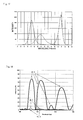
- the wavelength characteristic of reflectance of the multilayer film is shown.
- the characteristic for p-polarization of an incident angle of 22.5° the characteristic for p-polarization of an incident angle 49.2°, and the characteristic for p-polarization of an incident angle of 67.5° are shown.
- the angular characteristic of reflectance for p-polarization of a wavelength of 550 nm of the multilayer film is shown.
- an improvement has been carried out by optimizing the layer thickness of each layer using a computer based on the multilayer film in the first embodiment.
- FIG. 37 the configuration of the multilayer film is shown.
- FIG. 11 the wavelength characteristic of reflectance of the multilayer film is shown.
- FIG. 11 the characteristic for p-polarization of an incident angle of 22.5°, the characteristic for p-polarization of an incident angle 49.2°, and the characteristic for p-polarization of an incident angle of 67.5° are shown.
- FIG. 12 the angular characteristic of reflectance for p-polarization of a wavelength of 550 nm of the multilayer film is shown.
- FIG. 38 the configuration of the multilayer film is shown.
- the wavelength characteristic of reflectance of the multilayer film is shown.
- the characteristic for p-polarization of an incident angle of 22.5°, the characteristic for p-polarization of an incident angle 49.2°, and the characteristic for p-polarization of an incident angle of 67.5° are shown.
- the angular characteristic of reflectance for p-polarization of a wavelength of 550 nm of the multilayer film is shown.
- the reflectance Rp set for the multilayer film is 70%.
- FIG. 39 the configuration of the multilayer film is shown.
- the wavelength characteristic of reflectance of the multilayer film is shown.
- the characteristic for p-polarization of an incident angle of 22.5°, the characteristic for p-polarization of an incident angle 49.2°, and the characteristic for p-polarization of an incident angle of 67.5° are shown.
- the angular characteristic of reflectance for p-polarization of a wavelength of 550 nm of the multilayer film is shown.
- a multilayer film optimum when the wavelength component included in the image-carrying light flux L 1 is limited to a specific wavelength component was designed.
- an LED when used as the light source of the image display device 2 a , its light emission spectrum has three peaks corresponding to R color, G color, and B color, respectively, as shown in FIG. 17 .
- it can be regarded that what is included in the image-carrying light flux L 1 is only the three wavelength components corresponding to their peaks.
- the wavelength components to be reflected by the multilayer film in the present embodiment are limited to the three wavelength components, the amount of light of the image-carrying light flux L 1 to form a virtual image is hardly lost.
- FIG. 40 the configuration of the multilayer film is shown.
- FIG. 18 the wavelength characteristic of reflectance of the multilayer film is shown.
- the characteristic for p-polarization of an incident angle of 22.5°, the characteristic for p-polarization of an incident angle 49.2°, and the characteristic for p-polarization of an incident angle of 67.5° are shown.
- the section of the substrate 1 of the present eyeglass display (the section formed when cut in a plane parallel to the YZ plane) is a rectangle (square).
- the section of the substrate 1 may be a triangle.
- the image-carrying light flux L 1 propagates through the substrate 1 while being internally reflected at three surfaces, for example, as shown by arrows in FIG. 19( a ).
- the components of the image-carrying light flux L 1 are the three components LI, LII, and LIII.
- the section of the substrate 1 may be another rectangle.
- the image-carrying light flux L 1 propagates through the substrate 1 while being internally reflected at four surfaces, for example, as shown in FIG. 19( b ).
- the components of the image-carrying light flux L 1 are the four components LI, LII, LIII, and LIV.
- the section of the substrate 1 may be a pentagon as shown in FIG. 19( c ).
- the image-carrying light flux L 1 propagates through the substrate 1 while being internally reflected at five surfaces, for example, as shown in FIG. 19( c ).
- the components of the image-carrying light flux L 1 are the five components LI, LII, LIII, LIV, and LV.
- a not shown deflection mirror is provided to the substrate 1 so that the image-carrying light flux L 1 that propagates through the substrate 1 shown in FIGS. 19( a ) to 19 ( c ) is emitted from any one of these surfaces.
- the introduction mirror 1 A is arranged inside the substrate 1 so that the image-carrying light flux L 1 is internally reflected at all of the other surfaces of the plurality of surfaces having substantially the vertical relationship to the section vertical to the surface of the substrate 1 from which the image-carrying light flux L 1 is emitted and the surface shown in FIG. 19 from which the image-carrying light flux L 1 is emitted, and the deflection mirror 1 B is arranged inside the substrate 1 or on the surface of the substrate 1 so that the image-carrying light flux L 1 is emitted to the outside of the substrate 1 , an eyeglass display having the same function as that of the present eyeglass display is realized.
- any two of the sides of the substrate 1 are parallel to each other. Therefore, it is possible to improve the visual recognizability of the external by making parallel the boundary surface (the side of the substrate 1 ) present between the eye of the viewer (viewing eye) and the external.
- a holographic optical film can be also used instead of a multilayer film.
- a holographic optical film can be used instead of a multilayer film.
- a holographic optical film that plays the same role as those can also be used. In this case, the plane substrate 1 ′ is not necessary.
- a holographic optical film that plays the same role as those can also be used.
- the plane substrate 1 ′ is not necessary.
- a holographic optical film will be described, which can be applied instead of the plurality of the deflection mirrors 1 B and the optical film 1 D shown in FIG. 6 .
- FIG. 20 To manufacture the holographic optical film, for example, an exposure optical system shown in FIG. 20 is used.
- a laser light source is denoted by symbol 51 ;
- a beam splitter is denoted by symbol BS;
- a mirror by symbol M is denoted by symbol M;
- a beam expander by symbol 53 ;
- a photosensitive material by symbol 54 .
- FIG. 21 is a conceptual diagram showing the substrate 1 in which the holographic optical film 54 is formed and the state of the image-carrying light flux that propagates through the substrate 1 .
- the holographic optical film 54 is provided on the surface 1 a of the substrate 1 .
- the holographic optical film 54 diffracts an image-carrying light flux (Lin) that is internally reflected inside and propagates through the substrate 1 and converts it into a light flux (Lout) that is emitted to the outside of the substrate 1 .
- the holographic optical film 54 can control the emission direction of an image-carrying light flux.
- injection molding using a fine die, microlithography, etc. can be applied in addition to the exposure by the exposure optical system shown in FIG. 20 .
- FIG. 22 is an outside appearance of the present stereophonic virtual image display.
- the present stereophonic virtual image display includes a plurality of image display optical systems 60 consisting of the substrate 1 and the image-introduction unit 2 of any one of the eyeglass displays in the first embodiment.
- the introduction mirror 1 A and the plurality of the deflection mirrors 1 B are provided in a predetermined relationship.
- the substrate 1 of the individual image display optical systems 60 is elongate in the horizontal direction when viewed from the viewer and has a rod-like shape elongated in the vertical direction.
- the image-introduction unit 2 is linked to one end of the substrate 1 .
- the plurality of the image display optical systems 60 are arranged side by side in the horizontal direction in front of the viewer.
- the exit pupils of the individual image display optical systems 60 are formed on the side of the viewer side by side in the horizontal direction.
- the right and left eyes of the viewer are arranged in any region in which the exit pupil is formed.
- an image supply unit 61 is connected to the individual image display optical systems 60 .
- the image supply unit 61 outputs the signal of an L-Ch image to be displayed to the left eye of the viewer and the signal of an R-Ch image to be displayed to the right eye of the viewer.
- the L-Ch image and the R-Ch image are stereogram images.
- the signal of the L-Ch image is input to the image display optical systems 60 arranged alternately, respectively.
- Each of these image display optical systems 60 forms a virtual image of the L-Ch image at a position a predetermined distance behind the image display optical system 60 , respectively.
- the signal of the R-Ch image is input to the rest of the image display optical systems 60 , respectively.
- Each of these image display optical systems 60 forms a virtual image of the R-Ch image at a position a predetermined distance behind the image display optical system 60 , respectively. Consequently, the viewer can, when placing the pupils of the right and left eyes at any position of the exit pupil, view the virtual images of the L-Ch image and the R-Ch image.
- the viewer can view the virtual image with the angle of view wide both longitudinally and transversely even though the substrate 1 is the elongated rod-like shape.
- the image display optical system 60 that displays the L-Ch image and the image display optical system 60 that displays the R-Ch image are arranged an angle of ⁇ c apart from each other.
- the angle ⁇ c is caused to coincide with the angle of congestion when the viewer views an object present at the predetermined distance with both eyes. Consequently, the viewer can view the L-Ch image with left eye and the R-Ch image with right eye, respectively. As a result, a vivid stereophonic virtual image can be viewed.
- the image display optical systems 60 are arranged in a wide range, it is possible to widen the range of arrangement of the eye for the viewer to view the stereophonic virtual image. Further, a plurality of viewers can view the same stereophonic virtual image simultaneously.
- the present embodiment is one of a 360-degree stereophonic virtual image display.
- a method of acquiring signals to be supplied to the present stereophonic virtual image display will be described.
- an object is photographed at each of n kinds of equidistant positions from the object.
- Each of the n kinds of positions is one of positions equally divided into n positions at an angle of 360° divided by n around the object.
- n image signals (signal of 1-Ch image, signal of 2-Ch image, . . . , signal of n-Ch image) are recorded.
- the division number n is set to a sufficiently great value so that a 360-degree stereophonic virtual image, to be described later, can be viewed successively.
- the configuration of the present stereophonic virtual image display will be described.
- FIG. 25 is an outside appearance of the present stereophonic virtual image display.
- the present stereophonic virtual image display includes n of the image display optical systems 60 consisting of the substrate 1 and the image-introduction unit 2 of any one of the eyeglass displays in the first embodiment.
- the introduction mirror 1 A and the plurality of the deflection mirrors 1 B are provided in a predetermined relationship.
- the substrate 1 of the individual image display optical systems 60 is thin in the horizontal direction when viewed from the viewer and has a rod-like shape elongated in the vertical direction.
- the image-introduction unit 2 is linked to one end of the substrate 1 .
- the n image display optical systems 60 are arranged in a cylindrical form in front of the viewer.
- the exit pupils of the individual image display optical systems 60 are formed side by side on the outside of the cylinder.
- the right and left eyes of the viewer are arranged at any position of the exit pupil.
- a controller 62 is connected to the individual image display optical systems 60 .
- the controller 62 outputs the n signals (signal of 1-Ch image, signal of 2-Ch image, . . . , signal of n-Ch image) recorded in advance.
- the n signals are input to the n image display optical systems 60 , individually.
- Each of these image display optical systems 60 forms the virtual images of 1-Ch image, 2-Ch image, . . . , n-Ch image at the center position of the cylinder, respectively.
- the viewer can, when arranging the pupil of the eye at any position of the cylindrical exit pupil, view the virtual image of the image corresponding to the position (virtual image of the object when viewed from the position). Further, the viewer can, when shifting the position of arrangement of the eye in the circumferential direction of the cylinder, view the virtual image of the object when viewed from the shifted position. In other words, the viewer can view the 360-degree stereophonic virtual image of the object.
- the viewer can view the virtual image with the angle of view wide both longitudinally and transversely even though the substrate 1 is the elongated rod-like shape.
- the present stereophonic virtual image display if signals of still images are used, it is possible to view a 360-degree stereophonic virtual image of the still images, and if signals of motion images are used, it is possible to view a 360-degree stereophonic virtual image of the motion images.
- signals of the image acquired by photographing the object are used, signals of an image combined by a computer may be used.
- the present embodiment is one of a liquid crystal display.
- FIG. 26 is an outside appearance of the present liquid crystal display.
- the present liquid crystal display includes a liquid crystal panel 80 and an illuminating optical system 70 that illuminates it from behind.
- the illuminating optical system 70 consists of the substrate 1 and an illuminating unit 2 ′ of any one of the eyeglass displays in the first embodiment.
- the introduction mirror 1 A and the plurality of the deflection mirrors 1 B are provided in a predetermined relationship.
- the substrate 1 in the present embodiment has a shape large in size in the longitudinal and transverse directions and thin in depth.
- the introduction mirror 1 A is arranged in one of the four corners, as shown in FIG. 27 , and the plurality of the deflection mirrors 1 B is arranged side by side substantially all over the surface.
- the illuminating unit 2 ′ emits an illumination light flux to illuminate each position of the liquid crystal panel 80 toward the introduction mirror 1 A.
- the illumination light flux propagates through the substrate 1 while being reflected internally and is deflected toward the outside of the substrate 1 by the plurality of the deflection mirrors 1 B, and thus each position of substantially all of the surfaces of the liquid crystal panel 80 is illuminated.
- the opening angle of the illumination light flux that illuminates the liquid crystal panel 80 is kept wide both longitudinally and transversely as with the image-carrying light flux L 1 in the first embodiment.
- the present liquid crystal display is a high-performance liquid crystal display with which the viewer can visually recognize an image in the angular range wide both longitudinally and transversely.
- the present liquid crystal display has various uses, such as in TV, mobile phone, display of a personal computer, etc.
Abstract
Description
b=2 tan−1[(Ds−d 0)/2L 0] (1)
“Ds” is the longitudinal dimension of the
α=cos θx
β=cos θy
γ=cos θz
AI=(α,β,γ)
AI is the direction cosine of the component LI of the light ray on the axis of the image-carrying light flux L1 immediately after reflected by the
AII=(α,−β,γ)
AII is the direction cosine of the component LII of the light ray on the axis of the image-carrying light flux L1, a parameter of the direction of the component LII.
AIII=(α,β,−γ)
AIII is the direction cosine of the component LIII of the light ray on the axis of the image-carrying light flux L1, a parameter of the direction of the component LIII.
AIV=(α,−β,−γ)
AIV is the direction cosine of the component LIV of the light ray on the axis of the image-carrying light flux L1, a parameter of the direction of the component LIV. Incidentally, the relationship among the parameters AI, AII, AIII, and AIV results from the fact that when the light ray on the axis of the image-carrying light flux L1 is reflected by any one of the
A i=(αi,βi,γi)
Ai is the direction cosine of the optical axis of the image-carrying light flux L1 incident to the
A 0=(α0,β0,γ0)
A0 is the direction cosine of the normal of the
A=any one of AI, AII, AIII, and AIV
A is the direction cosine of the light ray on the axis of the image-carrying light flux L1 that propagates through the
A m=(αm,βm,γm)
Am is the direction cosine of the normal of the
A′=(α′,β′,γ′)
A′ is the direction cosine of the light ray on the axis of the image-carrying light flux L1 emitted to the eye of the viewer from the
A 0=(−A i +A)/(2 cos θ0) (2)
cos 2θ0 =A i ·A (3)
The expression (3) can be transformed into expression (3′):
cos θ0=√[(αiα+βiβ+γiγ+1)/2] (3′)
In addition, by the same way of thinking, the selection of the parameter Am of the arrangement attitude of the
A m=(−A+A′)/(2 cos θa) (4)
cos 2θa =A·A′ (5)
By the way, as described above, the light ray on the axis of the image-carrying light flux L1 is composed of any one of the four components (LI to LIV) irrespective of its position. A characteristic is given to the
-
- (−135°, 67.5°),
- (−135°, 22.5°),
- (135°, 67.5°),
- (135°, 22.5°).
-
- Component L1: 67.5° (the component to emit light to outside of substrate 1),
- Component LII: 22.5°,
- Component LIII: 74.3°,
- Component LIV: 74.3°
In addition, as shown in the bottom right boxes inFIG. 33 , according to the parameters inFIG. 33 , the incident angles of the four components LI, LII, LIII, and LIV for thedeflection mirror 1B are the following four angles: - Component LI: 67.5°,
- Component LII: 22.5° (the component to emit light to outside of substrate 1),
- Component LIII: 49.21°,
- Component LIV: 49.21°
In addition, as shown in the bottom right boxes inFIG. 34 , according to the parameters inFIG. 34 , the incident angles of the four components LI, LII, LIII, and LIV for thedeflection mirror 1B are the following four angles: - Component LI: 74.3°,
- Component LII: 74.3°,
- Component LIII: 67.5° (the component to emit light to outside of substrate 1),
- Component LIV: 22.5°
In addition, as shown in the bottom right boxes inFIG. 35 , according to the parameters inFIG. 35 , the incident angles of the four components LI, LII, LIII, and LIV for thedeflection mirror 1B are the following four angles. - Component LI: 49.21°,
- Component LII: 49.21°,
- Component LIII: 67.5°,
- Component LIV: 22.5° (the component to emit light to outside of substrate 1)
As a result of the comparison described above, it can be seen that the case where the reflection angle region and the transmission angle region can be separated by one threshold value is that shown inFIG. 33 or that shown inFIG. 35 . Because of this, the parameters are narrowed down to those inFIG. 33 orFIG. 35 , which is the case where thedeflection mirror 1B can be manufactured easily using the multilayer film.
First Embodiment of Multilayer Film
Substrate/(0.25H0.25L)p0.25H/Substrate,
Substrate/(0.125H0.25L0.125H)p/Substrate,
Substrate/(0.125L0.25H0.125L)p/Substrate,
where:
-
- “H”: High-refractive index layer (H layer),
- “L”: Low-refractive index layer (L layer),
- “p”: Number of times of lamination of the layer group in the brackets.
The numerical value on the left side of each layer is the layer thickness of each layer (in units of design dominant wavelength λc).
-
- Refractive index of the substrate 1: 1.56,
- Refractive index of H layer: 1.67,
- Refractive index of L layer: 1.46,
- Design dominant wavelength λc: 450 nm
Substrate/(0.125H0.25L0.125H)7(0.15H0.3L0.15H)7
(0.175H0.35L0.175H)7(0.205H0.41L0.205H)7/Substrate
In
-
- Refractive index of the substrate 1: 1.56,
- Refractive index of H layer: 2.30,
- Refractive index of L layer: 1.46,
- Design dominant wavelength λc: 450 nm
-
- Reflectance Rp: 70%,
- Refractive index of the substrate 1: 1.56,
- Refractive index of H layer: 2.30,
- Refractive index of L layer: 1.46,
- Design dominant wavelength λc: 450 nm
Claims (17)
Applications Claiming Priority (3)
| Application Number | Priority Date | Filing Date | Title |
|---|---|---|---|
| JP2004-353006 | 2004-12-06 | ||
| JP2004353006 | 2004-12-06 | ||
| PCT/JP2005/015656 WO2006061927A1 (en) | 2004-12-06 | 2005-08-29 | Image display optical system, image display unit, lighting optical system, and liquid crystral display unit |
Publications (2)
| Publication Number | Publication Date |
|---|---|
| US20080094586A1 US20080094586A1 (en) | 2008-04-24 |
| US7778508B2 true US7778508B2 (en) | 2010-08-17 |
Family
ID=36577757
Family Applications (1)
| Application Number | Title | Priority Date | Filing Date |
|---|---|---|---|
| US11/792,218 Expired - Fee Related US7778508B2 (en) | 2004-12-06 | 2005-08-29 | Image display optical system, image display unit, illuminating optical system, and liquid crystal display unit |
Country Status (3)
| Country | Link |
|---|---|
| US (1) | US7778508B2 (en) |
| JP (1) | JP5282358B2 (en) |
| WO (1) | WO2006061927A1 (en) |
Cited By (88)
| Publication number | Priority date | Publication date | Assignee | Title |
|---|---|---|---|---|
| US20100302644A1 (en) * | 2007-09-18 | 2010-12-02 | Mirage Innovations Ltd | Slanted optical device |
| US20120057253A1 (en) * | 2010-09-03 | 2012-03-08 | Seiko Epson Corporation | Light guide plate and virtual image display apparatus having the same |
| JP2012083458A (en) * | 2010-10-08 | 2012-04-26 | Seiko Epson Corp | Virtual image display device |
| CN103135235A (en) * | 2011-11-30 | 2013-06-05 | 索尼公司 | Light reflecting member, light beam extension device, image display device, and optical device |
| US9223137B2 (en) | 2010-10-08 | 2015-12-29 | Seiko Epson Corporation | Virtual image display apparatus |
| US9244281B1 (en) | 2013-09-26 | 2016-01-26 | Rockwell Collins, Inc. | Display system and method using a detached combiner |
| US9244280B1 (en) | 2014-03-25 | 2016-01-26 | Rockwell Collins, Inc. | Near eye display system and method for display enhancement or redundancy |
| US9274339B1 (en) | 2010-02-04 | 2016-03-01 | Rockwell Collins, Inc. | Worn display system and method without requiring real time tracking for boresight precision |
| US9341846B2 (en) | 2012-04-25 | 2016-05-17 | Rockwell Collins Inc. | Holographic wide angle display |
| US9366864B1 (en) | 2011-09-30 | 2016-06-14 | Rockwell Collins, Inc. | System for and method of displaying information without need for a combiner alignment detector |
| US9507150B1 (en) | 2011-09-30 | 2016-11-29 | Rockwell Collins, Inc. | Head up display (HUD) using a bent waveguide assembly |
| US9519089B1 (en) | 2014-01-30 | 2016-12-13 | Rockwell Collins, Inc. | High performance volume phase gratings |
| US9523852B1 (en) | 2012-03-28 | 2016-12-20 | Rockwell Collins, Inc. | Micro collimator system and method for a head up display (HUD) |
| US9674413B1 (en) | 2013-04-17 | 2017-06-06 | Rockwell Collins, Inc. | Vision system and method having improved performance and solar mitigation |
| US9715067B1 (en) | 2011-09-30 | 2017-07-25 | Rockwell Collins, Inc. | Ultra-compact HUD utilizing waveguide pupil expander with surface relief gratings in high refractive index materials |
| US9715110B1 (en) | 2014-09-25 | 2017-07-25 | Rockwell Collins, Inc. | Automotive head up display (HUD) |
| CN107430275A (en) * | 2015-02-19 | 2017-12-01 | 鲁姆斯有限公司 | Compact wear-type display system with homogeneous image |
| US9933684B2 (en) | 2012-11-16 | 2018-04-03 | Rockwell Collins, Inc. | Transparent waveguide display providing upper and lower fields of view having a specific light output aperture configuration |
| US10007117B2 (en) | 2015-09-10 | 2018-06-26 | Vuzix Corporation | Imaging light guide with reflective turning array |
| US10088675B1 (en) | 2015-05-18 | 2018-10-02 | Rockwell Collins, Inc. | Turning light pipe for a pupil expansion system and method |
| US10108010B2 (en) | 2015-06-29 | 2018-10-23 | Rockwell Collins, Inc. | System for and method of integrating head up displays and head down displays |
| US10126552B2 (en) | 2015-05-18 | 2018-11-13 | Rockwell Collins, Inc. | Micro collimator system and method for a head up display (HUD) |
| US10142603B2 (en) | 2015-03-02 | 2018-11-27 | Seiko Epson Corporation | Image display device, projector, and transmission type display device |
| US10156681B2 (en) | 2015-02-12 | 2018-12-18 | Digilens Inc. | Waveguide grating device |
| US10241330B2 (en) | 2014-09-19 | 2019-03-26 | Digilens, Inc. | Method and apparatus for generating input images for holographic waveguide displays |
| US10247943B1 (en) | 2015-05-18 | 2019-04-02 | Rockwell Collins, Inc. | Head up display (HUD) using a light pipe |
| US10261321B2 (en) | 2005-11-08 | 2019-04-16 | Lumus Ltd. | Polarizing optical system |
| US10295824B2 (en) | 2017-01-26 | 2019-05-21 | Rockwell Collins, Inc. | Head up display with an angled light pipe |
| US10302835B2 (en) | 2017-02-22 | 2019-05-28 | Lumus Ltd. | Light guide optical assembly |
| US10359736B2 (en) | 2014-08-08 | 2019-07-23 | Digilens Inc. | Method for holographic mastering and replication |
| TWI669530B (en) * | 2016-08-18 | 2019-08-21 | 以色列商盧姆斯有限公司 | Compact head-mounted display system having uniform image |
| US10437031B2 (en) | 2016-11-08 | 2019-10-08 | Lumus Ltd. | Light-guide device with optical cutoff edge and corresponding production methods |
| US10481319B2 (en) | 2017-03-22 | 2019-11-19 | Lumus Ltd. | Overlapping facets |
| US10509241B1 (en) | 2009-09-30 | 2019-12-17 | Rockwell Collins, Inc. | Optical displays |
| US10520731B2 (en) | 2014-11-11 | 2019-12-31 | Lumus Ltd. | Compact head-mounted display system protected by a hyperfine structure |
| US10545346B2 (en) | 2017-01-05 | 2020-01-28 | Digilens Inc. | Wearable heads up displays |
| US10551544B2 (en) | 2018-01-21 | 2020-02-04 | Lumus Ltd. | Light-guide optical element with multiple-axis internal aperture expansion |
| US10564417B2 (en) | 2016-10-09 | 2020-02-18 | Lumus Ltd. | Aperture multiplier using a rectangular waveguide |
| US10598932B1 (en) | 2016-01-06 | 2020-03-24 | Rockwell Collins, Inc. | Head up display for integrating views of conformally mapped symbols and a fixed image source |
| US10642058B2 (en) | 2011-08-24 | 2020-05-05 | Digilens Inc. | Wearable data display |
| US10649214B2 (en) | 2005-02-10 | 2020-05-12 | Lumus Ltd. | Substrate-guide optical device |
| US10670876B2 (en) | 2011-08-24 | 2020-06-02 | Digilens Inc. | Waveguide laser illuminator incorporating a despeckler |
| US10678053B2 (en) | 2009-04-27 | 2020-06-09 | Digilens Inc. | Diffractive projection apparatus |
| US10690916B2 (en) | 2015-10-05 | 2020-06-23 | Digilens Inc. | Apparatus for providing waveguide displays with two-dimensional pupil expansion |
| US10725312B2 (en) | 2007-07-26 | 2020-07-28 | Digilens Inc. | Laser illumination device |
| US10732407B1 (en) | 2014-01-10 | 2020-08-04 | Rockwell Collins, Inc. | Near eye head up display system and method with fixed combiner |
| US10732569B2 (en) | 2018-01-08 | 2020-08-04 | Digilens Inc. | Systems and methods for high-throughput recording of holographic gratings in waveguide cells |
| US10747982B2 (en) | 2013-07-31 | 2020-08-18 | Digilens Inc. | Method and apparatus for contact image sensing |
| US10795160B1 (en) | 2014-09-25 | 2020-10-06 | Rockwell Collins, Inc. | Systems for and methods of using fold gratings for dual axis expansion |
| US10809528B2 (en) | 2014-04-23 | 2020-10-20 | Lumus Ltd. | Compact head-mounted display system |
| US10859768B2 (en) | 2016-03-24 | 2020-12-08 | Digilens Inc. | Method and apparatus for providing a polarization selective holographic waveguide device |
| US10890707B2 (en) | 2016-04-11 | 2021-01-12 | Digilens Inc. | Holographic waveguide apparatus for structured light projection |
| US10895679B2 (en) | 2017-04-06 | 2021-01-19 | Lumus Ltd. | Light-guide optical element and method of its manufacture |
| US10914950B2 (en) | 2018-01-08 | 2021-02-09 | Digilens Inc. | Waveguide architectures and related methods of manufacturing |
| US10942430B2 (en) | 2017-10-16 | 2021-03-09 | Digilens Inc. | Systems and methods for multiplying the image resolution of a pixelated display |
| US11256155B2 (en) | 2012-01-06 | 2022-02-22 | Digilens Inc. | Contact image sensor using switchable Bragg gratings |
| US11300795B1 (en) | 2009-09-30 | 2022-04-12 | Digilens Inc. | Systems for and methods of using fold gratings coordinated with output couplers for dual axis expansion |
| US11307432B2 (en) | 2014-08-08 | 2022-04-19 | Digilens Inc. | Waveguide laser illuminator incorporating a Despeckler |
| US11314084B1 (en) | 2011-09-30 | 2022-04-26 | Rockwell Collins, Inc. | Waveguide combiner system and method with less susceptibility to glare |
| US11320571B2 (en) | 2012-11-16 | 2022-05-03 | Rockwell Collins, Inc. | Transparent waveguide display providing upper and lower fields of view with uniform light extraction |
| US11366316B2 (en) | 2015-05-18 | 2022-06-21 | Rockwell Collins, Inc. | Head up display (HUD) using a light pipe |
| US11378732B2 (en) | 2019-03-12 | 2022-07-05 | DigLens Inc. | Holographic waveguide backlight and related methods of manufacturing |
| US11402801B2 (en) | 2018-07-25 | 2022-08-02 | Digilens Inc. | Systems and methods for fabricating a multilayer optical structure |
| US11415812B2 (en) | 2018-06-26 | 2022-08-16 | Lumus Ltd. | Compact collimating optical device and system |
| US11442222B2 (en) | 2019-08-29 | 2022-09-13 | Digilens Inc. | Evacuated gratings and methods of manufacturing |
| US11448816B2 (en) | 2019-01-24 | 2022-09-20 | Lumus Ltd. | Optical systems including light-guide optical elements with two-dimensional expansion |
| US11487131B2 (en) | 2011-04-07 | 2022-11-01 | Digilens Inc. | Laser despeckler based on angular diversity |
| US11513350B2 (en) | 2016-12-02 | 2022-11-29 | Digilens Inc. | Waveguide device with uniform output illumination |
| US11523092B2 (en) | 2019-12-08 | 2022-12-06 | Lumus Ltd. | Optical systems with compact image projector |
| US11526003B2 (en) | 2018-05-23 | 2022-12-13 | Lumus Ltd. | Optical system including light-guide optical element with partially-reflective internal surfaces |
| US11543583B2 (en) | 2018-09-09 | 2023-01-03 | Lumus Ltd. | Optical systems including light-guide optical elements with two-dimensional expansion |
| US11543594B2 (en) | 2019-02-15 | 2023-01-03 | Digilens Inc. | Methods and apparatuses for providing a holographic waveguide display using integrated gratings |
| US11561335B2 (en) | 2019-12-05 | 2023-01-24 | Lumus Ltd. | Light-guide optical element employing complementary coated partial reflectors, and light-guide optical element having reduced light scattering |
| US11630260B2 (en) | 2020-05-24 | 2023-04-18 | Lumus Ltd. | Production method and corresponding structures of compound light-guide optical elements |
| US11644676B2 (en) | 2020-09-11 | 2023-05-09 | Lumus Ltd. | Image projector coupled to a light guide optical element |
| US11681143B2 (en) | 2019-07-29 | 2023-06-20 | Digilens Inc. | Methods and apparatus for multiplying the image resolution and field-of-view of a pixelated display |
| US11726332B2 (en) | 2009-04-27 | 2023-08-15 | Digilens Inc. | Diffractive projection apparatus |
| US11726329B2 (en) | 2015-01-12 | 2023-08-15 | Digilens Inc. | Environmentally isolated waveguide display |
| US11747568B2 (en) | 2019-06-07 | 2023-09-05 | Digilens Inc. | Waveguides incorporating transmissive and reflective gratings and related methods of manufacturing |
| US11789264B2 (en) | 2021-07-04 | 2023-10-17 | Lumus Ltd. | Display with stacked light-guide elements providing different parts of field of view |
| US11796729B2 (en) | 2021-02-25 | 2023-10-24 | Lumus Ltd. | Optical aperture multipliers having a rectangular waveguide |
| US11822088B2 (en) | 2021-05-19 | 2023-11-21 | Lumus Ltd. | Active optical engine |
| US11849262B2 (en) | 2019-03-12 | 2023-12-19 | Lumus Ltd. | Image projector |
| US11860369B2 (en) | 2021-03-01 | 2024-01-02 | Lumus Ltd. | Optical system with compact coupling from a projector into a waveguide |
| US11886008B2 (en) | 2021-08-23 | 2024-01-30 | Lumus Ltd. | Methods of fabrication of compound light-guide optical elements having embedded coupling-in reflectors |
| US11885966B2 (en) | 2019-12-30 | 2024-01-30 | Lumus Ltd. | Optical systems including light-guide optical elements with two-dimensional expansion |
| US11914161B2 (en) | 2019-06-27 | 2024-02-27 | Lumus Ltd. | Apparatus and methods for eye tracking based on eye imaging via light-guide optical element |
| US11914187B2 (en) | 2019-07-04 | 2024-02-27 | Lumus Ltd. | Image waveguide with symmetric beam multiplication |
Families Citing this family (36)
| Publication number | Priority date | Publication date | Assignee | Title |
|---|---|---|---|---|
| US7778508B2 (en) * | 2004-12-06 | 2010-08-17 | Nikon Corporation | Image display optical system, image display unit, illuminating optical system, and liquid crystal display unit |
| KR100772383B1 (en) * | 2005-11-22 | 2007-11-01 | 삼성전자주식회사 | Compact rear projection display |
| IL177618A (en) | 2006-08-22 | 2015-02-26 | Lumus Ltd | Substrate- guided optical device |
| FR2911408B1 (en) * | 2007-01-16 | 2009-11-20 | Essilor Int | OPTO-ELECTRONIC DISPLAY DEVICE WITH OPTICAL INSERT ENCAPSULATED IN AN OPHTHALMIC LENS |
| FR2925172B1 (en) * | 2007-12-13 | 2010-08-20 | Optinvent | OPTICAL GUIDE AND OPTICAL SYSTEM OF OCULAR VISION. |
| FR2925171B1 (en) * | 2007-12-13 | 2010-04-16 | Optinvent | OPTICAL GUIDE AND OPTICAL SYSTEM OF EYE VISION |
| WO2009117870A1 (en) * | 2008-03-26 | 2009-10-01 | 深圳航天科技创新研究院 | Spectacles type display device using single display chip |
| JP5133925B2 (en) * | 2009-03-25 | 2013-01-30 | オリンパス株式会社 | Head-mounted image display device |
| US8059342B2 (en) * | 2009-04-03 | 2011-11-15 | Vuzix Corporation | Beam segmentor for enlarging viewing aperture of microdisplay |
| JP5152101B2 (en) * | 2009-05-29 | 2013-02-27 | 株式会社島津製作所 | Display device |
| WO2011024291A1 (en) * | 2009-08-28 | 2011-03-03 | 株式会社島津製作所 | Display device |
| JP5901321B2 (en) | 2012-02-06 | 2016-04-06 | オリンパス株式会社 | Image display device |
| CN104737061B (en) | 2012-06-11 | 2018-01-16 | 奇跃公司 | Use more depth plane three dimensional displays of the waveguided reflector arrays projector |
| EP2895910A4 (en) | 2012-09-11 | 2016-04-20 | Magic Leap Inc | Ergonomic head mounted display device and optical system |
| JP6197864B2 (en) * | 2013-03-11 | 2017-09-20 | コニカミノルタ株式会社 | Wearable computer |
| JP2014225725A (en) * | 2013-05-15 | 2014-12-04 | ソニー株式会社 | Display device and light source for image display device |
| JP6367529B2 (en) | 2013-06-25 | 2018-08-01 | ソニー株式会社 | Display device, display control method, display control device, and electronic apparatus |
| DE102013219623B4 (en) * | 2013-09-27 | 2015-05-21 | Carl Zeiss Ag | Spectacle lens for a display device which can be placed on the head of a user and generates an image, and a display device with such a spectacle lens |
| CN110764267B (en) * | 2014-01-09 | 2022-04-19 | 三星电子株式会社 | Wearable display device |
| DE102014207500B3 (en) * | 2014-04-17 | 2015-05-07 | Carl Zeiss Ag | Spectacle lens for a display device that can be placed on the head of a user and forms an image |
| IL236490B (en) * | 2014-12-25 | 2021-10-31 | Lumus Ltd | Substrate-guided optical device |
| JP6651703B2 (en) * | 2015-03-25 | 2020-02-19 | セイコーエプソン株式会社 | Virtual image display |
| JP2015179297A (en) * | 2015-07-03 | 2015-10-08 | セイコーエプソン株式会社 | Manufacturing method of light guide plate, and light guide plate |
| JP6552338B2 (en) * | 2015-08-26 | 2019-07-31 | 株式会社東芝 | Display device |
| JP5983841B2 (en) * | 2015-09-02 | 2016-09-06 | セイコーエプソン株式会社 | Virtual image display device |
| WO2017077934A1 (en) * | 2015-11-06 | 2017-05-11 | シャープ株式会社 | Light guide and virtual image display device |
| CN110612470B (en) * | 2017-05-30 | 2022-10-28 | 索尼公司 | Optical device, image display device, and display device |
| CN110869839B (en) | 2017-07-19 | 2022-07-08 | 鲁姆斯有限公司 | Liquid crystal on silicon illuminator with light guide optical element |
| CA3082067C (en) * | 2017-11-21 | 2023-08-01 | Lumus Ltd. | Optical aperture expansion arrangement for near-eye displays |
| KR20200096274A (en) | 2017-12-03 | 2020-08-11 | 루머스 리미티드 | Optical device alignment method |
| WO2019111927A1 (en) * | 2017-12-07 | 2019-06-13 | キヤノン株式会社 | Display device and head mounted display |
| US11221294B2 (en) | 2018-04-08 | 2022-01-11 | Lumus Ltd. | Optical sample characterization |
| IL259518B2 (en) | 2018-05-22 | 2023-04-01 | Lumus Ltd | Optical system and method for improvement of light field uniformity |
| IL270991B (en) * | 2019-11-27 | 2020-07-30 | Lumus Ltd | Lightguide optical element for polarization scrambling |
| JP7380240B2 (en) * | 2020-01-20 | 2023-11-15 | 株式会社リコー | Light guide member and virtual image display device |
| GB2604402B (en) | 2021-03-05 | 2023-08-23 | Envisics Ltd | Head-up display |
Citations (13)
| Publication number | Priority date | Publication date | Assignee | Title |
|---|---|---|---|---|
| US4309070A (en) | 1979-01-19 | 1982-01-05 | Smiths Industries Limited | Display apparatus |
| US5341230A (en) * | 1992-12-22 | 1994-08-23 | Hughes Aircraft Company | Waveguide holographic telltale display |
| US5594830A (en) * | 1992-03-23 | 1997-01-14 | Minnesota Mining And Manufacturing Co. | Luminaire device |
| US5892598A (en) * | 1994-07-15 | 1999-04-06 | Matsushita Electric Industrial Co., Ltd. | Head up display unit, liquid crystal display panel, and method of fabricating the liquid crystal display panel |
| US5898511A (en) * | 1992-09-03 | 1999-04-27 | Nippondenso Co., Ltd. | Process for making holograms and holography device |
| JP2001110218A (en) | 1999-10-08 | 2001-04-20 | Internatl Business Mach Corp <Ibm> | Light conducting device, backlight device and liquid crystal display device |
| US20030137823A1 (en) | 2002-01-18 | 2003-07-24 | Junji Miyashita | Lighting panel for a display assembly |
| JP2003536102A (en) | 2000-06-05 | 2003-12-02 | ラマス リミテッド | Optical beam expander guided by substrate |
| JP2004111384A (en) | 2002-08-30 | 2004-04-08 | Hitachi Chem Co Ltd | Light guide plate and backlight device |
| US20040085649A1 (en) * | 2002-07-17 | 2004-05-06 | C.R.F. Societa Consortile Per Azioni | Light guide for display devices of the head-mounted or head-up type |
| EP1544537A1 (en) | 2002-08-30 | 2005-06-22 | Hitachi Chemical Co., Ltd. | Light guide plate and backlight device |
| US20080094586A1 (en) * | 2004-12-06 | 2008-04-24 | Yoshikazu Hirayama | Image Display Optical System, Image Display Unit, Illuminating Optical System, And Liquid Crystal Display Unit |
| US20090154198A1 (en) * | 2007-12-14 | 2009-06-18 | Joo Hoon Lee | Reflection type display apparatus |
Family Cites Families (6)
| Publication number | Priority date | Publication date | Assignee | Title |
|---|---|---|---|---|
| JP2000221899A (en) * | 1999-01-29 | 2000-08-11 | Matsushita Electric Ind Co Ltd | Display device |
| JP2000227554A (en) * | 1999-02-05 | 2000-08-15 | Olympus Optical Co Ltd | Image-formation optical system |
| JP4325064B2 (en) * | 2000-03-17 | 2009-09-02 | コニカミノルタホールディングス株式会社 | Information display optics |
| JP2002090690A (en) * | 2000-09-13 | 2002-03-27 | Olympus Optical Co Ltd | Image display device |
| JP2003140081A (en) * | 2001-11-06 | 2003-05-14 | Nikon Corp | Hologram combiner optical system |
| JP4072456B2 (en) * | 2003-05-08 | 2008-04-09 | キヤノン株式会社 | Display optical system, image display device, and image display system |
-
2005
- 2005-08-29 US US11/792,218 patent/US7778508B2/en not_active Expired - Fee Related
- 2005-08-29 WO PCT/JP2005/015656 patent/WO2006061927A1/en active Application Filing
- 2005-08-29 JP JP2006547651A patent/JP5282358B2/en active Active
Patent Citations (18)
| Publication number | Priority date | Publication date | Assignee | Title |
|---|---|---|---|---|
| US4309070A (en) | 1979-01-19 | 1982-01-05 | Smiths Industries Limited | Display apparatus |
| US5594830A (en) * | 1992-03-23 | 1997-01-14 | Minnesota Mining And Manufacturing Co. | Luminaire device |
| US5898511A (en) * | 1992-09-03 | 1999-04-27 | Nippondenso Co., Ltd. | Process for making holograms and holography device |
| US5341230A (en) * | 1992-12-22 | 1994-08-23 | Hughes Aircraft Company | Waveguide holographic telltale display |
| US5892598A (en) * | 1994-07-15 | 1999-04-06 | Matsushita Electric Industrial Co., Ltd. | Head up display unit, liquid crystal display panel, and method of fabricating the liquid crystal display panel |
| JP2001110218A (en) | 1999-10-08 | 2001-04-20 | Internatl Business Mach Corp <Ibm> | Light conducting device, backlight device and liquid crystal display device |
| US6667782B1 (en) | 1999-10-08 | 2003-12-23 | International Business Machines Corporation | Light guide apparatus, a backlight apparatus and a liquid crystal display apparatus |
| JP2003536102A (en) | 2000-06-05 | 2003-12-02 | ラマス リミテッド | Optical beam expander guided by substrate |
| US6829095B2 (en) | 2000-06-05 | 2004-12-07 | Lumus, Ltd. | Substrate-guided optical beam expander |
| JP2003215346A (en) | 2002-01-18 | 2003-07-30 | Citizen Electronics Co Ltd | Light guide plat |
| US20030137823A1 (en) | 2002-01-18 | 2003-07-24 | Junji Miyashita | Lighting panel for a display assembly |
| US20040085649A1 (en) * | 2002-07-17 | 2004-05-06 | C.R.F. Societa Consortile Per Azioni | Light guide for display devices of the head-mounted or head-up type |
| JP2004157520A (en) | 2002-07-17 | 2004-06-03 | Crf Soc Consortile Per Azioni | Head-mount or head-up type light guide member for use in display device |
| US6825987B2 (en) | 2002-07-17 | 2004-11-30 | C.R.F. Societa Consortile Per Azioni | Light guide for display devices of the head-mounted or head-up type |
| JP2004111384A (en) | 2002-08-30 | 2004-04-08 | Hitachi Chem Co Ltd | Light guide plate and backlight device |
| EP1544537A1 (en) | 2002-08-30 | 2005-06-22 | Hitachi Chemical Co., Ltd. | Light guide plate and backlight device |
| US20080094586A1 (en) * | 2004-12-06 | 2008-04-24 | Yoshikazu Hirayama | Image Display Optical System, Image Display Unit, Illuminating Optical System, And Liquid Crystal Display Unit |
| US20090154198A1 (en) * | 2007-12-14 | 2009-06-18 | Joo Hoon Lee | Reflection type display apparatus |
Non-Patent Citations (1)
| Title |
|---|
| International Preliminary Report on Patentability, dated Jun. 21, 2007, from corresponding application No. PCT/JP2005/015656, filed Aug. 29, 2005. |
Cited By (137)
| Publication number | Priority date | Publication date | Assignee | Title |
|---|---|---|---|---|
| US10649214B2 (en) | 2005-02-10 | 2020-05-12 | Lumus Ltd. | Substrate-guide optical device |
| US10962784B2 (en) | 2005-02-10 | 2021-03-30 | Lumus Ltd. | Substrate-guide optical device |
| US11187905B2 (en) | 2005-11-08 | 2021-11-30 | Lumus Ltd. | Polarizing optical system |
| US10261321B2 (en) | 2005-11-08 | 2019-04-16 | Lumus Ltd. | Polarizing optical system |
| US10598937B2 (en) | 2005-11-08 | 2020-03-24 | Lumus Ltd. | Polarizing optical system |
| US10725312B2 (en) | 2007-07-26 | 2020-07-28 | Digilens Inc. | Laser illumination device |
| US20100302644A1 (en) * | 2007-09-18 | 2010-12-02 | Mirage Innovations Ltd | Slanted optical device |
| US11726332B2 (en) | 2009-04-27 | 2023-08-15 | Digilens Inc. | Diffractive projection apparatus |
| US10678053B2 (en) | 2009-04-27 | 2020-06-09 | Digilens Inc. | Diffractive projection apparatus |
| US11175512B2 (en) | 2009-04-27 | 2021-11-16 | Digilens Inc. | Diffractive projection apparatus |
| US11300795B1 (en) | 2009-09-30 | 2022-04-12 | Digilens Inc. | Systems for and methods of using fold gratings coordinated with output couplers for dual axis expansion |
| US10509241B1 (en) | 2009-09-30 | 2019-12-17 | Rockwell Collins, Inc. | Optical displays |
| US9274339B1 (en) | 2010-02-04 | 2016-03-01 | Rockwell Collins, Inc. | Worn display system and method without requiring real time tracking for boresight precision |
| US8662686B2 (en) * | 2010-09-03 | 2014-03-04 | Seiko Epson Corporation | Light guide plate and virtual image display apparatus having the same |
| US20120057253A1 (en) * | 2010-09-03 | 2012-03-08 | Seiko Epson Corporation | Light guide plate and virtual image display apparatus having the same |
| US9223137B2 (en) | 2010-10-08 | 2015-12-29 | Seiko Epson Corporation | Virtual image display apparatus |
| US9784974B2 (en) | 2010-10-08 | 2017-10-10 | Seiko Epson Corporation | Virtual image display apparatus |
| JP2012083458A (en) * | 2010-10-08 | 2012-04-26 | Seiko Epson Corp | Virtual image display device |
| US11487131B2 (en) | 2011-04-07 | 2022-11-01 | Digilens Inc. | Laser despeckler based on angular diversity |
| US10642058B2 (en) | 2011-08-24 | 2020-05-05 | Digilens Inc. | Wearable data display |
| US11287666B2 (en) | 2011-08-24 | 2022-03-29 | Digilens, Inc. | Wearable data display |
| US10670876B2 (en) | 2011-08-24 | 2020-06-02 | Digilens Inc. | Waveguide laser illuminator incorporating a despeckler |
| US9977247B1 (en) | 2011-09-30 | 2018-05-22 | Rockwell Collins, Inc. | System for and method of displaying information without need for a combiner alignment detector |
| US9715067B1 (en) | 2011-09-30 | 2017-07-25 | Rockwell Collins, Inc. | Ultra-compact HUD utilizing waveguide pupil expander with surface relief gratings in high refractive index materials |
| US9599813B1 (en) | 2011-09-30 | 2017-03-21 | Rockwell Collins, Inc. | Waveguide combiner system and method with less susceptibility to glare |
| US10401620B1 (en) | 2011-09-30 | 2019-09-03 | Rockwell Collins, Inc. | Waveguide combiner system and method with less susceptibility to glare |
| US9507150B1 (en) | 2011-09-30 | 2016-11-29 | Rockwell Collins, Inc. | Head up display (HUD) using a bent waveguide assembly |
| US9366864B1 (en) | 2011-09-30 | 2016-06-14 | Rockwell Collins, Inc. | System for and method of displaying information without need for a combiner alignment detector |
| US11314084B1 (en) | 2011-09-30 | 2022-04-26 | Rockwell Collins, Inc. | Waveguide combiner system and method with less susceptibility to glare |
| CN103135235A (en) * | 2011-11-30 | 2013-06-05 | 索尼公司 | Light reflecting member, light beam extension device, image display device, and optical device |
| US9759920B2 (en) | 2011-11-30 | 2017-09-12 | Sony Corporation | Light reflecting member, light beam extension device, image display device, and optical device |
| CN103135235B (en) * | 2011-11-30 | 2016-11-23 | 索尼公司 | Light reflecting member, beam expansion device, image display device and Optical devices |
| US11256155B2 (en) | 2012-01-06 | 2022-02-22 | Digilens Inc. | Contact image sensor using switchable Bragg gratings |
| US9523852B1 (en) | 2012-03-28 | 2016-12-20 | Rockwell Collins, Inc. | Micro collimator system and method for a head up display (HUD) |
| US10690915B2 (en) | 2012-04-25 | 2020-06-23 | Rockwell Collins, Inc. | Holographic wide angle display |
| US9341846B2 (en) | 2012-04-25 | 2016-05-17 | Rockwell Collins Inc. | Holographic wide angle display |
| US11460621B2 (en) | 2012-04-25 | 2022-10-04 | Rockwell Collins, Inc. | Holographic wide angle display |
| US11448937B2 (en) | 2012-11-16 | 2022-09-20 | Digilens Inc. | Transparent waveguide display for tiling a display having plural optical powers using overlapping and offset FOV tiles |
| US11320571B2 (en) | 2012-11-16 | 2022-05-03 | Rockwell Collins, Inc. | Transparent waveguide display providing upper and lower fields of view with uniform light extraction |
| US20180373115A1 (en) * | 2012-11-16 | 2018-12-27 | Digilens, Inc. | Transparent Waveguide Display |
| US9933684B2 (en) | 2012-11-16 | 2018-04-03 | Rockwell Collins, Inc. | Transparent waveguide display providing upper and lower fields of view having a specific light output aperture configuration |
| US11815781B2 (en) | 2012-11-16 | 2023-11-14 | Rockwell Collins, Inc. | Transparent waveguide display |
| US9674413B1 (en) | 2013-04-17 | 2017-06-06 | Rockwell Collins, Inc. | Vision system and method having improved performance and solar mitigation |
| US9679367B1 (en) | 2013-04-17 | 2017-06-13 | Rockwell Collins, Inc. | HUD system and method with dynamic light exclusion |
| US10747982B2 (en) | 2013-07-31 | 2020-08-18 | Digilens Inc. | Method and apparatus for contact image sensing |
| US9244281B1 (en) | 2013-09-26 | 2016-01-26 | Rockwell Collins, Inc. | Display system and method using a detached combiner |
| US10732407B1 (en) | 2014-01-10 | 2020-08-04 | Rockwell Collins, Inc. | Near eye head up display system and method with fixed combiner |
| US9519089B1 (en) | 2014-01-30 | 2016-12-13 | Rockwell Collins, Inc. | High performance volume phase gratings |
| US9766465B1 (en) | 2014-03-25 | 2017-09-19 | Rockwell Collins, Inc. | Near eye display system and method for display enhancement or redundancy |
| US9244280B1 (en) | 2014-03-25 | 2016-01-26 | Rockwell Collins, Inc. | Near eye display system and method for display enhancement or redundancy |
| US10809528B2 (en) | 2014-04-23 | 2020-10-20 | Lumus Ltd. | Compact head-mounted display system |
| US10908426B2 (en) | 2014-04-23 | 2021-02-02 | Lumus Ltd. | Compact head-mounted display system |
| US11709373B2 (en) | 2014-08-08 | 2023-07-25 | Digilens Inc. | Waveguide laser illuminator incorporating a despeckler |
| US10359736B2 (en) | 2014-08-08 | 2019-07-23 | Digilens Inc. | Method for holographic mastering and replication |
| US11307432B2 (en) | 2014-08-08 | 2022-04-19 | Digilens Inc. | Waveguide laser illuminator incorporating a Despeckler |
| US10241330B2 (en) | 2014-09-19 | 2019-03-26 | Digilens, Inc. | Method and apparatus for generating input images for holographic waveguide displays |
| US11726323B2 (en) | 2014-09-19 | 2023-08-15 | Digilens Inc. | Method and apparatus for generating input images for holographic waveguide displays |
| US10795160B1 (en) | 2014-09-25 | 2020-10-06 | Rockwell Collins, Inc. | Systems for and methods of using fold gratings for dual axis expansion |
| US11579455B2 (en) | 2014-09-25 | 2023-02-14 | Rockwell Collins, Inc. | Systems for and methods of using fold gratings for dual axis expansion using polarized light for wave plates on waveguide faces |
| US9715110B1 (en) | 2014-09-25 | 2017-07-25 | Rockwell Collins, Inc. | Automotive head up display (HUD) |
| US11543661B2 (en) | 2014-11-11 | 2023-01-03 | Lumus Ltd. | Compact head-mounted display system protected by a hyperfine structure |
| US10782532B2 (en) | 2014-11-11 | 2020-09-22 | Lumus Ltd. | Compact head-mounted display system protected by a hyperfine structure |
| US10520731B2 (en) | 2014-11-11 | 2019-12-31 | Lumus Ltd. | Compact head-mounted display system protected by a hyperfine structure |
| US11726329B2 (en) | 2015-01-12 | 2023-08-15 | Digilens Inc. | Environmentally isolated waveguide display |
| US11740472B2 (en) | 2015-01-12 | 2023-08-29 | Digilens Inc. | Environmentally isolated waveguide display |
| US11703645B2 (en) | 2015-02-12 | 2023-07-18 | Digilens Inc. | Waveguide grating device |
| US10156681B2 (en) | 2015-02-12 | 2018-12-18 | Digilens Inc. | Waveguide grating device |
| US10527797B2 (en) | 2015-02-12 | 2020-01-07 | Digilens Inc. | Waveguide grating device |
| US20180039082A1 (en) * | 2015-02-19 | 2018-02-08 | Lumus Ltd. | Compact head-mounted display system having uniform image |
| CN107430275A (en) * | 2015-02-19 | 2017-12-01 | 鲁姆斯有限公司 | Compact wear-type display system with homogeneous image |
| US10142603B2 (en) | 2015-03-02 | 2018-11-27 | Seiko Epson Corporation | Image display device, projector, and transmission type display device |
| US10746989B2 (en) | 2015-05-18 | 2020-08-18 | Rockwell Collins, Inc. | Micro collimator system and method for a head up display (HUD) |
| US11366316B2 (en) | 2015-05-18 | 2022-06-21 | Rockwell Collins, Inc. | Head up display (HUD) using a light pipe |
| US10247943B1 (en) | 2015-05-18 | 2019-04-02 | Rockwell Collins, Inc. | Head up display (HUD) using a light pipe |
| US10698203B1 (en) | 2015-05-18 | 2020-06-30 | Rockwell Collins, Inc. | Turning light pipe for a pupil expansion system and method |
| US10126552B2 (en) | 2015-05-18 | 2018-11-13 | Rockwell Collins, Inc. | Micro collimator system and method for a head up display (HUD) |
| US10088675B1 (en) | 2015-05-18 | 2018-10-02 | Rockwell Collins, Inc. | Turning light pipe for a pupil expansion system and method |
| US10108010B2 (en) | 2015-06-29 | 2018-10-23 | Rockwell Collins, Inc. | System for and method of integrating head up displays and head down displays |
| US10007117B2 (en) | 2015-09-10 | 2018-06-26 | Vuzix Corporation | Imaging light guide with reflective turning array |
| US11754842B2 (en) | 2015-10-05 | 2023-09-12 | Digilens Inc. | Apparatus for providing waveguide displays with two-dimensional pupil expansion |
| US10690916B2 (en) | 2015-10-05 | 2020-06-23 | Digilens Inc. | Apparatus for providing waveguide displays with two-dimensional pupil expansion |
| US11281013B2 (en) | 2015-10-05 | 2022-03-22 | Digilens Inc. | Apparatus for providing waveguide displays with two-dimensional pupil expansion |
| US10598932B1 (en) | 2016-01-06 | 2020-03-24 | Rockwell Collins, Inc. | Head up display for integrating views of conformally mapped symbols and a fixed image source |
| US11215834B1 (en) | 2016-01-06 | 2022-01-04 | Rockwell Collins, Inc. | Head up display for integrating views of conformally mapped symbols and a fixed image source |
| US10859768B2 (en) | 2016-03-24 | 2020-12-08 | Digilens Inc. | Method and apparatus for providing a polarization selective holographic waveguide device |
| US11604314B2 (en) | 2016-03-24 | 2023-03-14 | Digilens Inc. | Method and apparatus for providing a polarization selective holographic waveguide device |
| US10890707B2 (en) | 2016-04-11 | 2021-01-12 | Digilens Inc. | Holographic waveguide apparatus for structured light projection |
| TWI669530B (en) * | 2016-08-18 | 2019-08-21 | 以色列商盧姆斯有限公司 | Compact head-mounted display system having uniform image |
| US10564417B2 (en) | 2016-10-09 | 2020-02-18 | Lumus Ltd. | Aperture multiplier using a rectangular waveguide |
| US11567316B2 (en) | 2016-10-09 | 2023-01-31 | Lumus Ltd. | Aperture multiplier with depolarizer |
| US11953682B2 (en) | 2016-10-09 | 2024-04-09 | Lumus Ltd. | Aperture multiplier with depolarizer |
| US10437031B2 (en) | 2016-11-08 | 2019-10-08 | Lumus Ltd. | Light-guide device with optical cutoff edge and corresponding production methods |
| US11378791B2 (en) | 2016-11-08 | 2022-07-05 | Lumus Ltd. | Light-guide device with optical cutoff edge and corresponding production methods |
| US11513350B2 (en) | 2016-12-02 | 2022-11-29 | Digilens Inc. | Waveguide device with uniform output illumination |
| US11586046B2 (en) | 2017-01-05 | 2023-02-21 | Digilens Inc. | Wearable heads up displays |
| US11194162B2 (en) | 2017-01-05 | 2021-12-07 | Digilens Inc. | Wearable heads up displays |
| US10545346B2 (en) | 2017-01-05 | 2020-01-28 | Digilens Inc. | Wearable heads up displays |
| US10295824B2 (en) | 2017-01-26 | 2019-05-21 | Rockwell Collins, Inc. | Head up display with an angled light pipe |
| US10705337B2 (en) | 2017-01-26 | 2020-07-07 | Rockwell Collins, Inc. | Head up display with an angled light pipe |
| US10302835B2 (en) | 2017-02-22 | 2019-05-28 | Lumus Ltd. | Light guide optical assembly |
| US10473841B2 (en) | 2017-02-22 | 2019-11-12 | Lumus Ltd. | Light guide optical assembly |
| US10684403B2 (en) | 2017-02-22 | 2020-06-16 | Lumus Ltd. | Light guide optical assembly |
| US11194084B2 (en) | 2017-02-22 | 2021-12-07 | Lumus Ltd. | Light guide optical assembly |
| US10481319B2 (en) | 2017-03-22 | 2019-11-19 | Lumus Ltd. | Overlapping facets |
| US11125927B2 (en) | 2017-03-22 | 2021-09-21 | Lumus Ltd. | Overlapping facets |
| US10895679B2 (en) | 2017-04-06 | 2021-01-19 | Lumus Ltd. | Light-guide optical element and method of its manufacture |
| US10942430B2 (en) | 2017-10-16 | 2021-03-09 | Digilens Inc. | Systems and methods for multiplying the image resolution of a pixelated display |
| US10914950B2 (en) | 2018-01-08 | 2021-02-09 | Digilens Inc. | Waveguide architectures and related methods of manufacturing |
| US10732569B2 (en) | 2018-01-08 | 2020-08-04 | Digilens Inc. | Systems and methods for high-throughput recording of holographic gratings in waveguide cells |
| US10551544B2 (en) | 2018-01-21 | 2020-02-04 | Lumus Ltd. | Light-guide optical element with multiple-axis internal aperture expansion |
| US11385393B2 (en) | 2018-01-21 | 2022-07-12 | Lumus Ltd. | Light-guide optical element with multiple-axis internal aperture expansion |
| US11526003B2 (en) | 2018-05-23 | 2022-12-13 | Lumus Ltd. | Optical system including light-guide optical element with partially-reflective internal surfaces |
| US11415812B2 (en) | 2018-06-26 | 2022-08-16 | Lumus Ltd. | Compact collimating optical device and system |
| US11402801B2 (en) | 2018-07-25 | 2022-08-02 | Digilens Inc. | Systems and methods for fabricating a multilayer optical structure |
| US11543583B2 (en) | 2018-09-09 | 2023-01-03 | Lumus Ltd. | Optical systems including light-guide optical elements with two-dimensional expansion |
| US11448816B2 (en) | 2019-01-24 | 2022-09-20 | Lumus Ltd. | Optical systems including light-guide optical elements with two-dimensional expansion |
| US11543594B2 (en) | 2019-02-15 | 2023-01-03 | Digilens Inc. | Methods and apparatuses for providing a holographic waveguide display using integrated gratings |
| US11378732B2 (en) | 2019-03-12 | 2022-07-05 | DigLens Inc. | Holographic waveguide backlight and related methods of manufacturing |
| US11849262B2 (en) | 2019-03-12 | 2023-12-19 | Lumus Ltd. | Image projector |
| US11747568B2 (en) | 2019-06-07 | 2023-09-05 | Digilens Inc. | Waveguides incorporating transmissive and reflective gratings and related methods of manufacturing |
| US11914161B2 (en) | 2019-06-27 | 2024-02-27 | Lumus Ltd. | Apparatus and methods for eye tracking based on eye imaging via light-guide optical element |
| US11914187B2 (en) | 2019-07-04 | 2024-02-27 | Lumus Ltd. | Image waveguide with symmetric beam multiplication |
| US11681143B2 (en) | 2019-07-29 | 2023-06-20 | Digilens Inc. | Methods and apparatus for multiplying the image resolution and field-of-view of a pixelated display |
| US11442222B2 (en) | 2019-08-29 | 2022-09-13 | Digilens Inc. | Evacuated gratings and methods of manufacturing |
| US11592614B2 (en) | 2019-08-29 | 2023-02-28 | Digilens Inc. | Evacuated gratings and methods of manufacturing |
| US11899238B2 (en) | 2019-08-29 | 2024-02-13 | Digilens Inc. | Evacuated gratings and methods of manufacturing |
| US11561335B2 (en) | 2019-12-05 | 2023-01-24 | Lumus Ltd. | Light-guide optical element employing complementary coated partial reflectors, and light-guide optical element having reduced light scattering |
| US11523092B2 (en) | 2019-12-08 | 2022-12-06 | Lumus Ltd. | Optical systems with compact image projector |
| US11885966B2 (en) | 2019-12-30 | 2024-01-30 | Lumus Ltd. | Optical systems including light-guide optical elements with two-dimensional expansion |
| US11630260B2 (en) | 2020-05-24 | 2023-04-18 | Lumus Ltd. | Production method and corresponding structures of compound light-guide optical elements |
| US11892677B2 (en) | 2020-05-24 | 2024-02-06 | Lumus Ltd. | Method of fabrication of compound light-guide optical elements |
| US11644676B2 (en) | 2020-09-11 | 2023-05-09 | Lumus Ltd. | Image projector coupled to a light guide optical element |
| US11796729B2 (en) | 2021-02-25 | 2023-10-24 | Lumus Ltd. | Optical aperture multipliers having a rectangular waveguide |
| US11860369B2 (en) | 2021-03-01 | 2024-01-02 | Lumus Ltd. | Optical system with compact coupling from a projector into a waveguide |
| US11822088B2 (en) | 2021-05-19 | 2023-11-21 | Lumus Ltd. | Active optical engine |
| US11789264B2 (en) | 2021-07-04 | 2023-10-17 | Lumus Ltd. | Display with stacked light-guide elements providing different parts of field of view |
| US11886008B2 (en) | 2021-08-23 | 2024-01-30 | Lumus Ltd. | Methods of fabrication of compound light-guide optical elements having embedded coupling-in reflectors |
Also Published As
| Publication number | Publication date |
|---|---|
| WO2006061927A1 (en) | 2006-06-15 |
| US20080094586A1 (en) | 2008-04-24 |
| JPWO2006061927A1 (en) | 2008-06-05 |
| JP5282358B2 (en) | 2013-09-04 |
Similar Documents
| Publication | Publication Date | Title |
|---|---|---|
| US7778508B2 (en) | Image display optical system, image display unit, illuminating optical system, and liquid crystal display unit | |
| US11143866B2 (en) | Waveguide including volume Bragg gratings | |
| KR101556839B1 (en) | Eyepiece for near-to-eye display with multi-reflectors | |
| US6989935B2 (en) | Optical arrangements for head mounted displays | |
| CN112867957B (en) | Waveguide for conveying multiple portions of a field of view | |
| JP7195496B2 (en) | Diffractive display, photopipe element and projector therefor, and method for displaying images | |
| CA2548398C (en) | Optical arrangements for head mounted displays | |
| WO2006025317A1 (en) | Light flux expanding optical system and imag display unit | |
| CN111352241A (en) | Head-mounted display | |
| US20230152592A1 (en) | Augmented reality display device | |
| US11686938B2 (en) | Augmented reality device for providing 3D augmented reality and operating method of the same | |
| US11675196B2 (en) | Wearable device with image display module | |
| US11555961B1 (en) | Display device with waveguide-based talbot illuminator | |
| EP4336482A1 (en) | An apparatus for projecting images towards a user | |
| US20230205065A1 (en) | Projector and display apparatus employing holographic optical element | |
| US20230314716A1 (en) | Emission of particular wavelength bands utilizing directed wavelength emission components in a display system | |
| US20230273435A1 (en) | Smart glasses with led projector arrays | |
| WO2023287897A1 (en) | Display device with waveguide-based talbot illuminator | |
| WO2023287605A1 (en) | Waveguide illuminator with optical interference mitigation | |
| CN117642575A (en) | Display device with waveguide-based taber illuminator | |
| CN116762024A (en) | Display device with transparent illuminator | |
| CN117642676A (en) | Waveguide illuminator for reducing optical interference | |
| JP5131331B2 (en) | Liquid crystal display | |
| CN117092825A (en) | Multi-focal-plane display device and AR near-to-eye display apparatus for resolving AR convergence adjustment conflict |
Legal Events
| Date | Code | Title | Description |
|---|---|---|---|
| AS | Assignment |
Owner name: NIKON CORPORATION, JAPAN Free format text: ASSIGNMENT OF ASSIGNORS INTEREST;ASSIGNOR:HIRAYAMA, YOSHIKAZU;REEL/FRAME:019433/0779 Effective date: 20070515 |
|
| STCF | Information on status: patent grant |
Free format text: PATENTED CASE |
|
| FEPP | Fee payment procedure |
Free format text: PAYOR NUMBER ASSIGNED (ORIGINAL EVENT CODE: ASPN); ENTITY STATUS OF PATENT OWNER: LARGE ENTITY |
|
| FPAY | Fee payment |
Year of fee payment: 4 |
|
| MAFP | Maintenance fee payment |
Free format text: PAYMENT OF MAINTENANCE FEE, 8TH YEAR, LARGE ENTITY (ORIGINAL EVENT CODE: M1552) Year of fee payment: 8 |
|
| FEPP | Fee payment procedure |
Free format text: MAINTENANCE FEE REMINDER MAILED (ORIGINAL EVENT CODE: REM.); ENTITY STATUS OF PATENT OWNER: LARGE ENTITY |
|
| LAPS | Lapse for failure to pay maintenance fees |
Free format text: PATENT EXPIRED FOR FAILURE TO PAY MAINTENANCE FEES (ORIGINAL EVENT CODE: EXP.); ENTITY STATUS OF PATENT OWNER: LARGE ENTITY |
|
| STCH | Information on status: patent discontinuation |
Free format text: PATENT EXPIRED DUE TO NONPAYMENT OF MAINTENANCE FEES UNDER 37 CFR 1.362 |
|
| FP | Lapsed due to failure to pay maintenance fee |
Effective date: 20220817 |