US7775413B2 - Cantilevered bar gap adjustment for an ultrasonic welding system - Google Patents
Cantilevered bar gap adjustment for an ultrasonic welding system Download PDFInfo
- Publication number
- US7775413B2 US7775413B2 US11/322,477 US32247705A US7775413B2 US 7775413 B2 US7775413 B2 US 7775413B2 US 32247705 A US32247705 A US 32247705A US 7775413 B2 US7775413 B2 US 7775413B2
- Authority
- US
- United States
- Prior art keywords
- horn
- gap
- anvil
- force
- length
- Prior art date
- Legal status (The legal status is an assumption and is not a legal conclusion. Google has not performed a legal analysis and makes no representation as to the accuracy of the status listed.)
- Active, expires
Links
Images


Classifications
-
- B—PERFORMING OPERATIONS; TRANSPORTING
- B23—MACHINE TOOLS; METAL-WORKING NOT OTHERWISE PROVIDED FOR
- B23K—SOLDERING OR UNSOLDERING; WELDING; CLADDING OR PLATING BY SOLDERING OR WELDING; CUTTING BY APPLYING HEAT LOCALLY, e.g. FLAME CUTTING; WORKING BY LASER BEAM
- B23K20/00—Non-electric welding by applying impact or other pressure, with or without the application of heat, e.g. cladding or plating
- B23K20/10—Non-electric welding by applying impact or other pressure, with or without the application of heat, e.g. cladding or plating making use of vibrations, e.g. ultrasonic welding
-
- B—PERFORMING OPERATIONS; TRANSPORTING
- B29—WORKING OF PLASTICS; WORKING OF SUBSTANCES IN A PLASTIC STATE IN GENERAL
- B29C—SHAPING OR JOINING OF PLASTICS; SHAPING OF MATERIAL IN A PLASTIC STATE, NOT OTHERWISE PROVIDED FOR; AFTER-TREATMENT OF THE SHAPED PRODUCTS, e.g. REPAIRING
- B29C65/00—Joining or sealing of preformed parts, e.g. welding of plastics materials; Apparatus therefor
- B29C65/02—Joining or sealing of preformed parts, e.g. welding of plastics materials; Apparatus therefor by heating, with or without pressure
- B29C65/08—Joining or sealing of preformed parts, e.g. welding of plastics materials; Apparatus therefor by heating, with or without pressure using ultrasonic vibrations
- B29C65/083—Joining or sealing of preformed parts, e.g. welding of plastics materials; Apparatus therefor by heating, with or without pressure using ultrasonic vibrations using a rotary sonotrode or a rotary anvil
- B29C65/085—Joining or sealing of preformed parts, e.g. welding of plastics materials; Apparatus therefor by heating, with or without pressure using ultrasonic vibrations using a rotary sonotrode or a rotary anvil using a rotary sonotrode
-
- B—PERFORMING OPERATIONS; TRANSPORTING
- B29—WORKING OF PLASTICS; WORKING OF SUBSTANCES IN A PLASTIC STATE IN GENERAL
- B29C—SHAPING OR JOINING OF PLASTICS; SHAPING OF MATERIAL IN A PLASTIC STATE, NOT OTHERWISE PROVIDED FOR; AFTER-TREATMENT OF THE SHAPED PRODUCTS, e.g. REPAIRING
- B29C66/00—General aspects of processes or apparatus for joining preformed parts
- B29C66/80—General aspects of machine operations or constructions and parts thereof
- B29C66/81—General aspects of the pressing elements, i.e. the elements applying pressure on the parts to be joined in the area to be joined, e.g. the welding jaws or clamps
- B29C66/812—General aspects of the pressing elements, i.e. the elements applying pressure on the parts to be joined in the area to be joined, e.g. the welding jaws or clamps characterised by the composition, by the structure, by the intensive physical properties or by the optical properties of the material constituting the pressing elements, e.g. constituting the welding jaws or clamps
- B29C66/8126—General aspects of the pressing elements, i.e. the elements applying pressure on the parts to be joined in the area to be joined, e.g. the welding jaws or clamps characterised by the composition, by the structure, by the intensive physical properties or by the optical properties of the material constituting the pressing elements, e.g. constituting the welding jaws or clamps characterised by the intensive physical properties or by the optical properties of the material constituting the pressing elements, e.g. constituting the welding jaws or clamps
- B29C66/81261—Thermal properties, e.g. thermal conductivity, thermal expansion coefficient
-
- B—PERFORMING OPERATIONS; TRANSPORTING
- B29—WORKING OF PLASTICS; WORKING OF SUBSTANCES IN A PLASTIC STATE IN GENERAL
- B29C—SHAPING OR JOINING OF PLASTICS; SHAPING OF MATERIAL IN A PLASTIC STATE, NOT OTHERWISE PROVIDED FOR; AFTER-TREATMENT OF THE SHAPED PRODUCTS, e.g. REPAIRING
- B29C66/00—General aspects of processes or apparatus for joining preformed parts
- B29C66/80—General aspects of machine operations or constructions and parts thereof
- B29C66/81—General aspects of the pressing elements, i.e. the elements applying pressure on the parts to be joined in the area to be joined, e.g. the welding jaws or clamps
- B29C66/818—General aspects of the pressing elements, i.e. the elements applying pressure on the parts to be joined in the area to be joined, e.g. the welding jaws or clamps characterised by the cooling constructional aspects, or by the thermal or electrical insulating or conducting constructional aspects of the welding jaws or of the clamps ; comprising means for compensating for the thermal expansion of the welding jaws or of the clamps
- B29C66/8185—General aspects of the pressing elements, i.e. the elements applying pressure on the parts to be joined in the area to be joined, e.g. the welding jaws or clamps characterised by the cooling constructional aspects, or by the thermal or electrical insulating or conducting constructional aspects of the welding jaws or of the clamps ; comprising means for compensating for the thermal expansion of the welding jaws or of the clamps comprising means for compensating for the thermal expansion of the welding jaws or of the clamps
-
- B—PERFORMING OPERATIONS; TRANSPORTING
- B29—WORKING OF PLASTICS; WORKING OF SUBSTANCES IN A PLASTIC STATE IN GENERAL
- B29C—SHAPING OR JOINING OF PLASTICS; SHAPING OF MATERIAL IN A PLASTIC STATE, NOT OTHERWISE PROVIDED FOR; AFTER-TREATMENT OF THE SHAPED PRODUCTS, e.g. REPAIRING
- B29C66/00—General aspects of processes or apparatus for joining preformed parts
- B29C66/80—General aspects of machine operations or constructions and parts thereof
- B29C66/82—Pressure application arrangements, e.g. transmission or actuating mechanisms for joining tools or clamps
- B29C66/824—Actuating mechanisms
- B29C66/8242—Pneumatic or hydraulic drives
- B29C66/82421—Pneumatic or hydraulic drives using an inflatable element positioned between the joining tool and a backing-up part
-
- B—PERFORMING OPERATIONS; TRANSPORTING
- B29—WORKING OF PLASTICS; WORKING OF SUBSTANCES IN A PLASTIC STATE IN GENERAL
- B29C—SHAPING OR JOINING OF PLASTICS; SHAPING OF MATERIAL IN A PLASTIC STATE, NOT OTHERWISE PROVIDED FOR; AFTER-TREATMENT OF THE SHAPED PRODUCTS, e.g. REPAIRING
- B29C66/00—General aspects of processes or apparatus for joining preformed parts
- B29C66/80—General aspects of machine operations or constructions and parts thereof
- B29C66/83—General aspects of machine operations or constructions and parts thereof characterised by the movement of the joining or pressing tools
- B29C66/832—Reciprocating joining or pressing tools
- B29C66/8322—Joining or pressing tools reciprocating along one axis
-
- B—PERFORMING OPERATIONS; TRANSPORTING
- B29—WORKING OF PLASTICS; WORKING OF SUBSTANCES IN A PLASTIC STATE IN GENERAL
- B29C—SHAPING OR JOINING OF PLASTICS; SHAPING OF MATERIAL IN A PLASTIC STATE, NOT OTHERWISE PROVIDED FOR; AFTER-TREATMENT OF THE SHAPED PRODUCTS, e.g. REPAIRING
- B29C66/00—General aspects of processes or apparatus for joining preformed parts
- B29C66/80—General aspects of machine operations or constructions and parts thereof
- B29C66/83—General aspects of machine operations or constructions and parts thereof characterised by the movement of the joining or pressing tools
- B29C66/836—Moving relative to and tangentially to the parts to be joined, e.g. transversely to the displacement of the parts to be joined, e.g. using a X-Y table
-
- B—PERFORMING OPERATIONS; TRANSPORTING
- B29—WORKING OF PLASTICS; WORKING OF SUBSTANCES IN A PLASTIC STATE IN GENERAL
- B29C—SHAPING OR JOINING OF PLASTICS; SHAPING OF MATERIAL IN A PLASTIC STATE, NOT OTHERWISE PROVIDED FOR; AFTER-TREATMENT OF THE SHAPED PRODUCTS, e.g. REPAIRING
- B29C66/00—General aspects of processes or apparatus for joining preformed parts
- B29C66/90—Measuring or controlling the joining process
- B29C66/92—Measuring or controlling the joining process by measuring or controlling the pressure, the force, the mechanical power or the displacement of the joining tools
- B29C66/924—Measuring or controlling the joining process by measuring or controlling the pressure, the force, the mechanical power or the displacement of the joining tools by controlling or regulating the pressure, the force, the mechanical power or the displacement of the joining tools
- B29C66/9241—Measuring or controlling the joining process by measuring or controlling the pressure, the force, the mechanical power or the displacement of the joining tools by controlling or regulating the pressure, the force, the mechanical power or the displacement of the joining tools by controlling or regulating the pressure, the force or the mechanical power
-
- B—PERFORMING OPERATIONS; TRANSPORTING
- B29—WORKING OF PLASTICS; WORKING OF SUBSTANCES IN A PLASTIC STATE IN GENERAL
- B29C—SHAPING OR JOINING OF PLASTICS; SHAPING OF MATERIAL IN A PLASTIC STATE, NOT OTHERWISE PROVIDED FOR; AFTER-TREATMENT OF THE SHAPED PRODUCTS, e.g. REPAIRING
- B29C66/00—General aspects of processes or apparatus for joining preformed parts
- B29C66/90—Measuring or controlling the joining process
- B29C66/92—Measuring or controlling the joining process by measuring or controlling the pressure, the force, the mechanical power or the displacement of the joining tools
- B29C66/924—Measuring or controlling the joining process by measuring or controlling the pressure, the force, the mechanical power or the displacement of the joining tools by controlling or regulating the pressure, the force, the mechanical power or the displacement of the joining tools
- B29C66/9261—Measuring or controlling the joining process by measuring or controlling the pressure, the force, the mechanical power or the displacement of the joining tools by controlling or regulating the pressure, the force, the mechanical power or the displacement of the joining tools by controlling or regulating the displacement of the joining tools
- B29C66/92611—Measuring or controlling the joining process by measuring or controlling the pressure, the force, the mechanical power or the displacement of the joining tools by controlling or regulating the pressure, the force, the mechanical power or the displacement of the joining tools by controlling or regulating the displacement of the joining tools by controlling or regulating the gap between the joining tools
- B29C66/92613—Measuring or controlling the joining process by measuring or controlling the pressure, the force, the mechanical power or the displacement of the joining tools by controlling or regulating the pressure, the force, the mechanical power or the displacement of the joining tools by controlling or regulating the displacement of the joining tools by controlling or regulating the gap between the joining tools the gap being kept constant over time
-
- B—PERFORMING OPERATIONS; TRANSPORTING
- B29—WORKING OF PLASTICS; WORKING OF SUBSTANCES IN A PLASTIC STATE IN GENERAL
- B29C—SHAPING OR JOINING OF PLASTICS; SHAPING OF MATERIAL IN A PLASTIC STATE, NOT OTHERWISE PROVIDED FOR; AFTER-TREATMENT OF THE SHAPED PRODUCTS, e.g. REPAIRING
- B29C66/00—General aspects of processes or apparatus for joining preformed parts
- B29C66/90—Measuring or controlling the joining process
- B29C66/92—Measuring or controlling the joining process by measuring or controlling the pressure, the force, the mechanical power or the displacement of the joining tools
- B29C66/924—Measuring or controlling the joining process by measuring or controlling the pressure, the force, the mechanical power or the displacement of the joining tools by controlling or regulating the pressure, the force, the mechanical power or the displacement of the joining tools
- B29C66/9261—Measuring or controlling the joining process by measuring or controlling the pressure, the force, the mechanical power or the displacement of the joining tools by controlling or regulating the pressure, the force, the mechanical power or the displacement of the joining tools by controlling or regulating the displacement of the joining tools
- B29C66/92651—Measuring or controlling the joining process by measuring or controlling the pressure, the force, the mechanical power or the displacement of the joining tools by controlling or regulating the pressure, the force, the mechanical power or the displacement of the joining tools by controlling or regulating the displacement of the joining tools by using stops
-
- B—PERFORMING OPERATIONS; TRANSPORTING
- B29—WORKING OF PLASTICS; WORKING OF SUBSTANCES IN A PLASTIC STATE IN GENERAL
- B29C—SHAPING OR JOINING OF PLASTICS; SHAPING OF MATERIAL IN A PLASTIC STATE, NOT OTHERWISE PROVIDED FOR; AFTER-TREATMENT OF THE SHAPED PRODUCTS, e.g. REPAIRING
- B29C66/00—General aspects of processes or apparatus for joining preformed parts
- B29C66/90—Measuring or controlling the joining process
- B29C66/95—Measuring or controlling the joining process by measuring or controlling specific variables not covered by groups B29C66/91 - B29C66/94
- B29C66/951—Measuring or controlling the joining process by measuring or controlling specific variables not covered by groups B29C66/91 - B29C66/94 by measuring or controlling the vibration frequency and/or the vibration amplitude of vibrating joining tools, e.g. of ultrasonic welding tools
- B29C66/9511—Measuring or controlling the joining process by measuring or controlling specific variables not covered by groups B29C66/91 - B29C66/94 by measuring or controlling the vibration frequency and/or the vibration amplitude of vibrating joining tools, e.g. of ultrasonic welding tools by measuring their vibration frequency
-
- B—PERFORMING OPERATIONS; TRANSPORTING
- B29—WORKING OF PLASTICS; WORKING OF SUBSTANCES IN A PLASTIC STATE IN GENERAL
- B29C—SHAPING OR JOINING OF PLASTICS; SHAPING OF MATERIAL IN A PLASTIC STATE, NOT OTHERWISE PROVIDED FOR; AFTER-TREATMENT OF THE SHAPED PRODUCTS, e.g. REPAIRING
- B29C66/00—General aspects of processes or apparatus for joining preformed parts
- B29C66/90—Measuring or controlling the joining process
- B29C66/95—Measuring or controlling the joining process by measuring or controlling specific variables not covered by groups B29C66/91 - B29C66/94
- B29C66/951—Measuring or controlling the joining process by measuring or controlling specific variables not covered by groups B29C66/91 - B29C66/94 by measuring or controlling the vibration frequency and/or the vibration amplitude of vibrating joining tools, e.g. of ultrasonic welding tools
- B29C66/9516—Measuring or controlling the joining process by measuring or controlling specific variables not covered by groups B29C66/91 - B29C66/94 by measuring or controlling the vibration frequency and/or the vibration amplitude of vibrating joining tools, e.g. of ultrasonic welding tools by controlling their vibration amplitude
-
- B—PERFORMING OPERATIONS; TRANSPORTING
- B29—WORKING OF PLASTICS; WORKING OF SUBSTANCES IN A PLASTIC STATE IN GENERAL
- B29C—SHAPING OR JOINING OF PLASTICS; SHAPING OF MATERIAL IN A PLASTIC STATE, NOT OTHERWISE PROVIDED FOR; AFTER-TREATMENT OF THE SHAPED PRODUCTS, e.g. REPAIRING
- B29C65/00—Joining or sealing of preformed parts, e.g. welding of plastics materials; Apparatus therefor
- B29C65/02—Joining or sealing of preformed parts, e.g. welding of plastics materials; Apparatus therefor by heating, with or without pressure
- B29C65/08—Joining or sealing of preformed parts, e.g. welding of plastics materials; Apparatus therefor by heating, with or without pressure using ultrasonic vibrations
- B29C65/083—Joining or sealing of preformed parts, e.g. welding of plastics materials; Apparatus therefor by heating, with or without pressure using ultrasonic vibrations using a rotary sonotrode or a rotary anvil
- B29C65/086—Joining or sealing of preformed parts, e.g. welding of plastics materials; Apparatus therefor by heating, with or without pressure using ultrasonic vibrations using a rotary sonotrode or a rotary anvil using a rotary anvil
-
- B—PERFORMING OPERATIONS; TRANSPORTING
- B29—WORKING OF PLASTICS; WORKING OF SUBSTANCES IN A PLASTIC STATE IN GENERAL
- B29C—SHAPING OR JOINING OF PLASTICS; SHAPING OF MATERIAL IN A PLASTIC STATE, NOT OTHERWISE PROVIDED FOR; AFTER-TREATMENT OF THE SHAPED PRODUCTS, e.g. REPAIRING
- B29C65/00—Joining or sealing of preformed parts, e.g. welding of plastics materials; Apparatus therefor
- B29C65/02—Joining or sealing of preformed parts, e.g. welding of plastics materials; Apparatus therefor by heating, with or without pressure
- B29C65/08—Joining or sealing of preformed parts, e.g. welding of plastics materials; Apparatus therefor by heating, with or without pressure using ultrasonic vibrations
- B29C65/083—Joining or sealing of preformed parts, e.g. welding of plastics materials; Apparatus therefor by heating, with or without pressure using ultrasonic vibrations using a rotary sonotrode or a rotary anvil
- B29C65/087—Joining or sealing of preformed parts, e.g. welding of plastics materials; Apparatus therefor by heating, with or without pressure using ultrasonic vibrations using a rotary sonotrode or a rotary anvil using both a rotary sonotrode and a rotary anvil
-
- B—PERFORMING OPERATIONS; TRANSPORTING
- B29—WORKING OF PLASTICS; WORKING OF SUBSTANCES IN A PLASTIC STATE IN GENERAL
- B29C—SHAPING OR JOINING OF PLASTICS; SHAPING OF MATERIAL IN A PLASTIC STATE, NOT OTHERWISE PROVIDED FOR; AFTER-TREATMENT OF THE SHAPED PRODUCTS, e.g. REPAIRING
- B29C66/00—General aspects of processes or apparatus for joining preformed parts
- B29C66/70—General aspects of processes or apparatus for joining preformed parts characterised by the composition, physical properties or the structure of the material of the parts to be joined; Joining with non-plastics material
- B29C66/73—General aspects of processes or apparatus for joining preformed parts characterised by the composition, physical properties or the structure of the material of the parts to be joined; Joining with non-plastics material characterised by the intensive physical properties of the material of the parts to be joined, by the optical properties of the material of the parts to be joined, by the extensive physical properties of the parts to be joined, by the state of the material of the parts to be joined or by the material of the parts to be joined being a thermoplastic or a thermoset
- B29C66/739—General aspects of processes or apparatus for joining preformed parts characterised by the composition, physical properties or the structure of the material of the parts to be joined; Joining with non-plastics material characterised by the intensive physical properties of the material of the parts to be joined, by the optical properties of the material of the parts to be joined, by the extensive physical properties of the parts to be joined, by the state of the material of the parts to be joined or by the material of the parts to be joined being a thermoplastic or a thermoset characterised by the material of the parts to be joined being a thermoplastic or a thermoset
- B29C66/7392—General aspects of processes or apparatus for joining preformed parts characterised by the composition, physical properties or the structure of the material of the parts to be joined; Joining with non-plastics material characterised by the intensive physical properties of the material of the parts to be joined, by the optical properties of the material of the parts to be joined, by the extensive physical properties of the parts to be joined, by the state of the material of the parts to be joined or by the material of the parts to be joined being a thermoplastic or a thermoset characterised by the material of the parts to be joined being a thermoplastic or a thermoset characterised by the material of at least one of the parts being a thermoplastic
- B29C66/73921—General aspects of processes or apparatus for joining preformed parts characterised by the composition, physical properties or the structure of the material of the parts to be joined; Joining with non-plastics material characterised by the intensive physical properties of the material of the parts to be joined, by the optical properties of the material of the parts to be joined, by the extensive physical properties of the parts to be joined, by the state of the material of the parts to be joined or by the material of the parts to be joined being a thermoplastic or a thermoset characterised by the material of the parts to be joined being a thermoplastic or a thermoset characterised by the material of at least one of the parts being a thermoplastic characterised by the materials of both parts being thermoplastics
-
- B—PERFORMING OPERATIONS; TRANSPORTING
- B29—WORKING OF PLASTICS; WORKING OF SUBSTANCES IN A PLASTIC STATE IN GENERAL
- B29C—SHAPING OR JOINING OF PLASTICS; SHAPING OF MATERIAL IN A PLASTIC STATE, NOT OTHERWISE PROVIDED FOR; AFTER-TREATMENT OF THE SHAPED PRODUCTS, e.g. REPAIRING
- B29C66/00—General aspects of processes or apparatus for joining preformed parts
- B29C66/80—General aspects of machine operations or constructions and parts thereof
- B29C66/81—General aspects of the pressing elements, i.e. the elements applying pressure on the parts to be joined in the area to be joined, e.g. the welding jaws or clamps
- B29C66/812—General aspects of the pressing elements, i.e. the elements applying pressure on the parts to be joined in the area to be joined, e.g. the welding jaws or clamps characterised by the composition, by the structure, by the intensive physical properties or by the optical properties of the material constituting the pressing elements, e.g. constituting the welding jaws or clamps
- B29C66/8122—General aspects of the pressing elements, i.e. the elements applying pressure on the parts to be joined in the area to be joined, e.g. the welding jaws or clamps characterised by the composition, by the structure, by the intensive physical properties or by the optical properties of the material constituting the pressing elements, e.g. constituting the welding jaws or clamps characterised by the composition of the material constituting the pressing elements, e.g. constituting the welding jaws or clamps
-
- B—PERFORMING OPERATIONS; TRANSPORTING
- B29—WORKING OF PLASTICS; WORKING OF SUBSTANCES IN A PLASTIC STATE IN GENERAL
- B29C—SHAPING OR JOINING OF PLASTICS; SHAPING OF MATERIAL IN A PLASTIC STATE, NOT OTHERWISE PROVIDED FOR; AFTER-TREATMENT OF THE SHAPED PRODUCTS, e.g. REPAIRING
- B29C66/00—General aspects of processes or apparatus for joining preformed parts
- B29C66/80—General aspects of machine operations or constructions and parts thereof
- B29C66/81—General aspects of the pressing elements, i.e. the elements applying pressure on the parts to be joined in the area to be joined, e.g. the welding jaws or clamps
- B29C66/818—General aspects of the pressing elements, i.e. the elements applying pressure on the parts to be joined in the area to be joined, e.g. the welding jaws or clamps characterised by the cooling constructional aspects, or by the thermal or electrical insulating or conducting constructional aspects of the welding jaws or of the clamps ; comprising means for compensating for the thermal expansion of the welding jaws or of the clamps
- B29C66/8181—General aspects of the pressing elements, i.e. the elements applying pressure on the parts to be joined in the area to be joined, e.g. the welding jaws or clamps characterised by the cooling constructional aspects, or by the thermal or electrical insulating or conducting constructional aspects of the welding jaws or of the clamps ; comprising means for compensating for the thermal expansion of the welding jaws or of the clamps characterised by the cooling constructional aspects
- B29C66/81811—General aspects of the pressing elements, i.e. the elements applying pressure on the parts to be joined in the area to be joined, e.g. the welding jaws or clamps characterised by the cooling constructional aspects, or by the thermal or electrical insulating or conducting constructional aspects of the welding jaws or of the clamps ; comprising means for compensating for the thermal expansion of the welding jaws or of the clamps characterised by the cooling constructional aspects of the welding jaws
- B29C66/81812—General aspects of the pressing elements, i.e. the elements applying pressure on the parts to be joined in the area to be joined, e.g. the welding jaws or clamps characterised by the cooling constructional aspects, or by the thermal or electrical insulating or conducting constructional aspects of the welding jaws or of the clamps ; comprising means for compensating for the thermal expansion of the welding jaws or of the clamps characterised by the cooling constructional aspects of the welding jaws the welding jaws being cooled from the outside, e.g. by blowing a gas or spraying a liquid
-
- B—PERFORMING OPERATIONS; TRANSPORTING
- B29—WORKING OF PLASTICS; WORKING OF SUBSTANCES IN A PLASTIC STATE IN GENERAL
- B29C—SHAPING OR JOINING OF PLASTICS; SHAPING OF MATERIAL IN A PLASTIC STATE, NOT OTHERWISE PROVIDED FOR; AFTER-TREATMENT OF THE SHAPED PRODUCTS, e.g. REPAIRING
- B29C66/00—General aspects of processes or apparatus for joining preformed parts
- B29C66/90—Measuring or controlling the joining process
- B29C66/95—Measuring or controlling the joining process by measuring or controlling specific variables not covered by groups B29C66/91 - B29C66/94
- B29C66/951—Measuring or controlling the joining process by measuring or controlling specific variables not covered by groups B29C66/91 - B29C66/94 by measuring or controlling the vibration frequency and/or the vibration amplitude of vibrating joining tools, e.g. of ultrasonic welding tools
- B29C66/9513—Measuring or controlling the joining process by measuring or controlling specific variables not covered by groups B29C66/91 - B29C66/94 by measuring or controlling the vibration frequency and/or the vibration amplitude of vibrating joining tools, e.g. of ultrasonic welding tools characterised by specific vibration frequency values or ranges
Definitions
- the present invention relates to a method and system for determining a gap between a vibrational body and a fixed point, and more particularly to a system and method arriving at such a determination based upon the resonant frequency of the vibrational body.
- ultrasonic welding In ultrasonic welding (sometimes referred to as “acoustic welding” or “sonic welding”), two parts to be joined (typically thermoplastic parts) are placed proximate a tool called an ultrasonic “horn” for delivering vibratory energy. These parts (or “workpieces”) are constrained between the horn and an anvil. Oftentimes, the horn is positioned vertically above the workpiece and the anvil. The horn vibrates, typically at 20,000 Hz to 40,000 Hz, transferring energy, typically in the form of frictional heat, under pressure, to the parts. Due to the frictional heat and pressure, a portion of at least one of the parts softens or is melted, thus joining the parts.
- an alternating current (AC) signal is supplied to a horn stack, which includes a converter, booster, and horn.
- the converter also referred to as a “transducer” receives the AC signal and responds thereto by compressing and expanding at a frequency equal to that of the AC signal. Therefore, acoustic waves travel through the converter to the booster. As the acoustic wavefront propagates through the booster, it is amplified, and is received by the horn. Finally, the wavefront propagates through the horn, and is imparted upon the workpieces, thereby welding them together, as previously described.
- ultrasonic welding Another type of ultrasonic welding is “continuous ultrasonic welding”. This type of ultrasonic welding is typically used for sealing fabrics and films, or other “web” workpieces, which can be fed through the welding apparatus in a generally continuous manner.
- the ultrasonic horn In continuous welding, the ultrasonic horn is typically stationary and the part to be welded is moved beneath it.
- One type of continuous ultrasonic welding uses a rotationally fixed bar horn and a rotating anvil. The workpiece is fed between the bar horn and the anvil. The horn typically extends longitudinally towards the workpiece and the vibrations travel axially along the horn into the workpiece.
- the horn is a rotary type, which is cylindrical and rotates about a longitudinal axis.
- the input vibration is in the axial direction of the horn and the output vibration is in the radial direction of the horn.
- the horn is placed close to an anvil, which typically is also able to rotate so that the workpiece to be welded passes between the cylindrical surfaces at a linear velocity, which substantially equals the tangential velocity of the cylindrical surfaces.
- the workpieces to be joined are disposed between the horn and the anvil, during the welding process.
- One way to weld is by fixing a gap between the horn and the anvil.
- the gap between the horn and anvil creates a pinching force that holds the workpieces in place while they are being joined.
- one or more components of the horn stack including the horn, itself, generally experience an elevation in temperature.
- the horn stack generally experiences thermal expansion.
- the gap between the horn and the anvil is decreased—a result inimical to the aforementioned goal of yielding a uniform and reliable welding operation.
- a method includes positioning a horn proximal to an anvil, so that a gap is established between the horn and the anvil.
- a force is applied to the horn, so as to urge the horn toward the anvil.
- a deformable stop is positioned at a location, such that application of the urging force causes a member operatively connected to the horn to abut the deformable stop, and to deform the stop.
- the urging force is iteratively adjusted during operation of the horn, so as to adjust the extent of the deformation of the deformable stop, and to maintain the gap between the horn and the anvil substantially constant.
- a system includes a mount including a translation member and a fixed elastic deformable stop.
- a horn is coupled to a source of ulstrasonic energy.
- the horn is operatively connected to the translating member.
- An anvil is separated from the horn by a gap.
- a force applicator is configured to urge the horn toward the anvil, and to cause a member operatively coupled to the horn to contact and deform the elastic deformable stop by varying degrees, so that the gap between the horn and the anvil remains substantially constant during operation of the system.
- a system includes a horn separated from an anvil by a mounting system.
- a source of ultrasonic energy is coupled to the horn.
- the system also includes a means for substantially maintaining the separation at a constant length, while the horn experiences thermal expansion.
- FIG. 1 depicts an embodiment of a simple ultrasonic welding horn stack coupled to an energy source.
- FIG. 2 depicts an embodiment of a mounting system coupled to the ultrasonic welding horn stack of FIG. 1 .
- FIG. 3 depicts an embodiment of a system for determining a length of a gap between a horn and an anvil.
- FIG. 4A depicts an exemplary embodiment of a table that may be used as a part of a gap-determining unit.
- FIG. 4B depicts an exemplary embodiment of a method of determining a gap length.
- FIG. 5A depicts an embodiment of a simple rotary ultrasonic welding horn for use in a continuous ultrasonic welding operation.
- FIG. 5B depicts an exemplary embodiment of a method of determining a gap length.
- FIG. 6 depicts an exemplary embodiment of a system for maintaining a substantially constant gap between a welding horn and an anvil.
- FIG. 7 depicts an exemplary embodiment of a system for adjusting a gap between a horn and an anvil in an ultrasonic welding system.
- FIG. 8A depicts an exemplary embodiment of a system for maintaining a susbtantially constant gap between a horn and an anvil in an ultrasonic welding system.
- FIG. 8B depicts another exemplary embodiment of a system for maintaining a susbtantially constant gap between a horn and an anvil in an ultrasonic welding system.
- FIG. 9A depicts an exemplary embodiment of a force-determining unit.
- FIG. 9B depicts another exemplary embodiment of a force-determining unit.
- FIG. 10 depicts an exemplary embodiment of a system for adjusting a gap between a horn and an anvil in an ultrasonic welding system.
- FIG. 11A depicts the surface of a horn driven by an acoustic signal propagating along the longitudinal axis of the horn.
- FIG. 11B depicts the surface of a horn driven by an acoustic signal of smaller magnitude than that of FIG. 11A , as that signal propagates along the longitudinal axis of the horn.
- FIG. 12A depicts an exemplary embodiment of a system for controlling the gap between a horn and an anvil.
- FIG. 12B depicts another exemplary embodiment of a system for controlling the gap between a horn and an anvil.
- FIG. 13 depicts an exemplary embodiment of a method for combining the operations of an adjustor and an amplitude determination module.
- FIG. 14 depicts another exemplary embodiment of a method for combining the operations of an adjustor and an amplitude determination module.
- FIG. 1 depicts an example of a simple horn stack 100 that is coupled to an AC source of electrical energy 102 .
- the horn stack 100 includes a converter 104 , a booster 106 , and an ultrasonic welding horn 108 .
- the AC source supplies electrical energy to the converter 104 , which responds thereto by compressing and expanding at a frequency equal to that of the AC signal. Therefore, acoustic waves travel through the converter 104 to the booster 106 . As the acoustic wavefront propagates through the booster 106 , it is amplified, and is received by the welding horn 108 .
- the horn 108 is designed to achieve a gain, eliminating the need for a booster 106 .
- the wavefront propagates through the horn 108 , whereupon it is imparted to workpieces (not depicted in FIG. 1 ) that are positioned between the welding horn 108 and an anvil 110 .
- workpieces not depicted in FIG. 1
- anvil 110 Other examples of horn stacks are known in the art, and function with the following systems, schemes, and methods disclosed herein.
- the horn 108 is separated from the anvil 110 by a distance labeled “Gap” in FIG. 1 .
- the process of imparting frictional energy to the workpieces causes the various elements of the horn stack 100 to elevate in temperature. As the elements of the horn stack 100 elevate in temperature, they exhibit thermal expansion, meaning that the gap between the horn 108 and the anvil 110 is likely to change in dimension, depending upon the particular manner in which the horn stack 100 is mounted.
- FIG. 2 depicts a simplified exemplary mounting scheme for the horn stack 100 of FIG. 1 .
- the mounting scheme makes use of a rigid, generally tripartite, frame 200 .
- the frame 200 includes a first portion 202 upon which the anvil 110 is mounted, and a second portion 206 that is adjoined to a nodal point on the horn stack 100 .
- the second portion 206 of the frame is depicted in FIG. 2 as being coupled to the midpoint 208 of the booster 106 .
- a third portion 204 of the frame 200 extends between the first and second portions 202 and 206 .
- the mounting system 200 maintains a substantially fixed distance between a workpiece-supporting surface 210 of the anvil 110 and a portion of the horn stack 100 .
- the mounting system 200 maintains a substantially fixed distance between the upper surface 210 of the anvil 110 and the midpoint/nodal point 208 of the booster 106 . Therefore, should the horn stack 100 expand during operation, the horn stack 100 expands outwardly from the midpoint 208 of the booster 106 , along the longitudinal axis of the stack 100 , as indicated by the arrows labeled “Expansion” in FIG. 2 .
- a variety of other mounting systems may also maintain a substantially fixed distance between the upper surface 210 of the anvil 110 and a portion of the horn stack 100 , and such other mounting systems are within the scope of the present application.
- thermal expansion of the converter 104 and upper portion of the booster 106 produces no effect on the gap length (because of the position of these elements relative to the point 208 at which the frame 200 joins the stack 100 , these elements are free to expand upwardly, i.e., away from the anvil 110 ).
- the gap length is affected by expansion of the lower portion of the booster 106 and by expansion of the horn 108 —as these elements expand, they expand toward the anvil 110 , and the gap contracts.
- the converter 104 and booster 106 are maintained at a substantially constant temperature.
- the converter 104 and booster 106 may be cooled by a cooling system, such as by one or more fans that circulate relatively cool air to the surfaces of the converter 104 and booster 106 , so as to substantially maintain their temperatures, and to thereby substantially suppress their thermal expansion. Therefore, according to such an embodiment, any change in length of the horn stack 100 may be considered as being substantially due to expansion of the welding horn 108 .
- the horn 108 is cooled by a cooling system, so as to suppress or reduce its propensity to heat up during operation.
- a cooling system so as to suppress or reduce its propensity to heat up during operation.
- such a scheme does not totally eliminate thermal expansion of the horn 108 , meaning that it still exhibits some degree of thermal expansion, which should be accounted for, if the gap length is to be maintained substantially constant.
- the length of a given body is inversely proportional to the given body's resonant frequency. Stated another way, as a body grows in length, it exhibits a lower resonant frequency. Therefore, as the horn stack 100 grows in length, as occurs, for example, by virtue of thermal expansion, it exhibits a lower resonant frequency. Specifically, the length of a body, l, is related to its resonant frequency, f by the following equation:
- E represents the modulus of elasticity of the object
- ⁇ represents the density of the object. If the object is compound (e.g., is made up of multiple parts or has various sections made from different materials, etc.), E and ⁇ may be assigned values representing the behavior of the materials, considering its various parts (e.g., may be a weighted average, etc.).
- the energy source 102 detects the resonant frequency, f, of the horn stack 100 , in order to generate an AC signal equal in frequency thereto.
- the energy source 102 may deliver a sinusiodal signal exhibiting a particular peak-to-peak voltage (or root-mean-square voltage) to the horn stack 100 .
- the energy source 102 adjusts the frequency of the signal, and seeks out the frequency at which the least current is drawn by the horn stack 100 —this frequency is the resonant frequency of the horn stack 100 .
- the resonant frequency of the stack 100 may be obtained from the energy source 102 .
- the resonant frequency of the stack 100 may be detected by observation of the stack 100 with a detector.
- the overall length of the stack 100 may be obtained by relating, in a manner similar to the aforementioned physical principles, resonant frequency to horn stack length.
- the length of the horn stack 100 can be related to the gap length.
- the gap length and the length of the horn 108 , l are related by the following equation: gap length ⁇ D ⁇ l, where D is an approximately constant value that represents the length between the top of the horn 108 and the workpiece-supporting surface 210 of the anvil 110 .
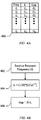
- FIG. 3 depicts a system for determining the length of the gap between a welding horn 108 and the workpiece-supporting surface 210 of the anvil 110 .
- the system of FIG. 3 includes an ultrasonic power supply 300 (e.g., an electrical power supply that delivers an AC signal to converter, which, in turn, transduces the signal into an acoustic wave) that delivers an acoustic signal to a horn (and booster) 302 .
- the ultrasonic power supply 300 is controlled by a controller circuit, such as by a processor in data communication with a memory device that stores firmware/software controlling the operation of the ultrasonic power supply 300 .
- the controller circuit may be embodied as a hardware-based control loop.
- the controller of the ultrasonic power supply 300 identifies the resonant frequency of the horn stack, and commands power supply signal generation circuitry therein to cooperate with the converter to yield an acoustic signal equal in frequency thereto.
- the controller within the power supply 300 may interface to a gap-determining unit 304 .
- the gap-determining unit 304 receives the resonant frequency of the horn stack, and generates a quantity standing in known relation to the gap length.
- the gap-determining unit 304 is a software module executing upon a processor coupled to a memory unit.
- the gap-determining unit 304 may execute upon the same processor upon which the firmware controlling the ultrasonic power supply 300 executes. Alternatively, it may execute upon a different processor that is in data communication therewith. In either event, the software/firmware executed by the gap-determining unit 304 may function according to the schemes (below) discussed with reference to FIGS. 4A-5B .
- the gap-determining unit 304 may receive the resonant frequency of the horn stack from a source other than the ultrasonic power supply 300 .
- the system may include a detector 306 that observes the horn stack, measures the resonant frequency thereof, and communicates the resonant frequency to the gap-determining unit 304 .
- the resonant frequency originates from the ultrasonic power supply 300 , for the sake of example only.
- FIG. 4A depicts a scheme by which the gap-determining unit 304 may operate.
- the gap-determining unit 304 may include a table 400 stored in a memory device.
- the table 400 is organized according to resonant frequency, and relates a gap length G to a resonant frequency, ⁇ .
- the gap-determining unit 304 uses the resonant frequency to access the table 400 , and to determine a gap length G corresponding to the resonant frequency, ⁇ . For example, assuming that the gap-determining unit 304 receives a frequency of ⁇ 2 as an input, the unit 304 responds by accessing the table 400 to identify a row corresponding to frequency ⁇ 2 .
- the gap length entered therein, G 2 is returned.
- the table 400 may be accessed to determine the length of the horn stack 100 , L, or to determine any other quantity standing in known relation to the gap length. Assuming that the gap-determining unit 304 receives a value f x as an input, and assuming that ⁇ x falls between successive table entries (i.e., ⁇ i ⁇ x ⁇ i+1 ), then the gap-determining unit 304 may access the table 400 to obtain gap length values G i and G i+1 , and may interpolate between the two values to arrive at a gap length corresponding to the resonant frequency, ⁇ x .
- the various entries in the table 400 may be populated ex ante by a heuristic process, in which the length of the horn stack 100 and the length of the gap are recorded for each frequency, ⁇ , within the table 400 .
- the various entries in the table 400 may be populated by theoretical calculation, in a manner similar to that described above.
- FIG. 4B depicts another scheme by which the gap-determining unit 304 may operate, theoretical computation.
- FIG. 5A depicts an example of a welding horn 500 that is used for continuous ultrasonic welding.
- the horn 500 therein includes a longitudinal axis 502 about which the horn 500 may rotate.
- the horn 500 is constrained by a mounting system (not depicted in FIG. 5A ), so that a gap is maintained between the horn and the anvil 504 .
- the horn stack may be mounted at any nodal point on the system.
- the longitudinal axis 502 of the horn is substantially parallel to the workpiece-supporting surface 506 of the anvil 504 .
- the aforementioned principle of determining the length of the gap between a horn and an anvil based upon the resonant frequency of the horn stack is applicable to the horn 500 of FIG. 5 .
- the following technique, depicted in FIG. 5B may be used to determine the length of the gap between the horn and the anvil.
- the resonant frequency of the horn stack is received. Thereafter, the length of the horn 502 , L, is determined based upon the frequency, in like manner as described above (operation 510 ). As before, the horn stack of FIG. 5A is cooled so that the converter (not depicted in FIG. 5A ) and booster (not depicted in FIG. 5A ) remain at substantially constant temperatures during operation, thereby suppressing their thermal expansion and the effects on the system resonant frequency.
- the ratio between its length, L, and its radius, B remains constant. Therefore, after calculation of the length of the horn 502 , its radius may be arrived at by multiplication of the length by the aforementioned ratio, B, as shown in operation 512 . Finally, the length of the gap may be determined by subtracting the radius from the distance, D, between the longitudinal axis of the horn 500 and workpiece-supporting surface 506 of the anvil 504 , as shown in operation 514 .
- results of the method described with respect to FIG. 5B may be stored within a table, as described with reference to FIG. 4A .
- the gap length, or any value standing in known relation thereto may be obtained by virtue of accessing such a table, based upon the resonant frequency of the horn stack.
- FIG. 6 depicts a control system for maintaining a substantially constant gap between a horn and an anvil, based upon observation of the resonant frequency of the horn stack.
- the system includes a horn stack 600 and a power supply 602 coupled thereto.
- the power supply 602 determines the resonant frequency of the horn stack 600 , as described above.
- the position adjustor 606 adjusts the horn stack 600 , either toward or away from the anvil, under the control of an input signal. A known relationship exists between the input signal delivered to the adjustor 606 and its response thereto.
- the position adjustor 606 is in data communication with a control signal generator 604 .
- the control signal generator 604 receives the resonant frequency of the horn stack as an input, and generates a control signal that is delivered to the position adjustor 606 .
- the control signal generator 604 yields a control signal that maintains a substantially constant gap between the anvil and the horn, given the resonant frequency of the horn stack 600 and the relationship between the response of the position adjustor 606 and its input signal.
- the control signal generator 604 may be embodied as a controller circuit, such as a processor in data communication with a memory device that stores firmware/software in accordance with the aforementioned principles. It may alternatively be embodied as an ASIC yielding the aforementioned control signal so as to maintain a substantially constant gap.
- a controller circuit such as a processor in data communication with a memory device that stores firmware/software in accordance with the aforementioned principles. It may alternatively be embodied as an ASIC yielding the aforementioned control signal so as to maintain a substantially constant gap.
- a position adjustor is disclosed. It is not necessary to use the position adjustor disclosed below for practice of the invention.
- the preceding portion of the specification was directed toward particular methods of determining the length of a horn or the length of a gap, based upon the resonant frequency of the horn stack. According to other embodiments, such determinations may be arrived at by measurement of the temperature of the horn stack, or of its various components.
- FIG. 7 depicts an exemplary embodiment of a system for adjusting the gap between a horn and an anvil.
- the system therein includes a horn 700 oriented above a workpiece-supporting surface 702 of an anvil 704 .
- the longitudinal axis LA of the horn 700 is substantially perpendicular to the support surface 702 of the anvil 704 .
- the frame 706 also includes a force-receiving plate 712 that is coupled to the frame 706 by a pair of members 714 .
- a force is applied to the force-receiving plate 712 by a force applicator (not depicted in FIG. 7 ).
- the force urges the horn 700 toward the anvil 704 .
- the direction of the force is indicated by the arrow 713 .
- the force has the effect of causing a contact surface 716 to abut an elastic deformable stop 718 .
- the force exerted upon the elastic deformable stop 718 causes the stop 718 to deform, and to thereby exhibit a downward deflection (i.e., a deflection in the direction of the anvil 704 ).
- the greater the force applied to the plate 712 the greater the downward deflection exhibited by the stop 718 .
- the greater the deflection exhibited by the stop 718 the smaller the gap between the horn 700 and the anvil 704 .
- the following scheme may be employed. While the horn 700 is at its unelevated temperature, an initial force is applied to the plate 712 , to cause the gap between the horn 700 and the anvil 704 to be established at an “ideal” length. As the horn 700 thermally expands during operation, the gap grows smaller. To counteract this effect, the force applied to the plate 712 is reduced, causing the stop 718 to exhibit a lesser deflection, meaning that the horn 700 and frame are translated upwardly (i.e., away from the anvil). Thus, the gap between the horn 700 and the anvil 704 may be maintained substantially constant by controlled application of force to the plate 712 . To ensure the functionality of this scheme the initial force applied to the plate 712 should be of sufficient magnitude to cause the stop 718 to exhibit a deflection at least as great in extent as the expected thermal expansion to be counteracted.
- the deformable stop 718 is elastic, and preferably has a relatively high modulus of elasticity. By selection of a material having a relatively high modulus of elasticity, a circumstance is set up in which the force required to deflect the stop 718 is relatively great compared to the process force (i.e., the force exerted by the horn on the workpiece). Such an arrangement provides for ease of control design.
- the stop 718 may be made of steel, or another suitable material.
- the force exerted upon the stop 718 does not cause the material therein to exit its elastic range (i.e., the stop 718 will return to its original shape upon withdrawal of the force).
- the stop 718 exhibits a deflection that is proportional to the force applied thereto, i.e., there exists a linear relationship between the force applied to the stop 718 and the extent of deflection exhibited thereby.
- FIG. 8A depicts an example of a control system for use with the exemplary adjustment system of FIG. 7 .
- the various units 804 - 810 of FIG. 8A may be embodied as software modules stored in a computer-readable medium and executed by a processor, or may be embodied as dedicated hardware, such as one or more application-specific integrated circuits, or as a field-programmable gate array. Further, the units 804 - 810 may be combined or divided as a matter of design choice.
- the system includes a horn 800 that is coupled to a source of ultrasonic power 802 .
- a gap-determining unit 804 determines the gap between the horn 800 and an anvil (not depicted in FIG. 8 ). According to one embodiment, the gap-determining unit 804 obtains the resonant frequency of the horn stack from the power source 802 , and determines the gap therefrom. According to another embodiment, the gap-determining unit 804 detects the resonant frequency of the horn 800 by observation thereof. According to yet another embodiment, the gap determining unit 804 arrives at the gap length by measurement of the temperature of the horn, inferring horn length therefrom, and arriving at the gap length on the basis of the horn length.
- the gap length arrived at by the gap-determining unit is supplied to a force-determining unit 806 .
- the force-determining unit 806 determines the force to be exerted upon the frame (e.g., plate 712 in FIG. 7 ), in order to maintain the gap at a substantially constant length.
- the force arrived at by the gap-determining unit 806 is supplied to a control signal generator 808 .
- the control signal generator 808 develops a control signal, and communicates that control signal to a force applicator 810 .
- the force applicator 810 exhibits a known relationship between the received control signal and the force it exerts. Thus, the control signal generator 808 develops the control signal in light of that relationship.
- FIG. 8B depicts exemplary embodiments of the gap determining unit 804 and force determining unit 806 .
- the various units of FIG. 8B may be embodied as software modules stored in a computer-readable medium and executed by a processor, or may be embodied as dedicated hardware, such as one or more application-specific integrated circuits, or as a field-programmable gate array. Further, the units of FIG. 8B may be combined or divided as a matter of design choice.
- the gap determining unit 804 includes a length determining unit 812 and a gap finding unit 814 .
- the length determining unit 812 receives the resonant frequency of the horn stack, and applies one of the methods described with reference to FIGS. 4A and 4B to find the length of the horn. Thereafter, the length of the horn is received by the gap finding unit 814 .
- the force-determining unit 806 After arrival at the gap length, this value is provided to the force-determining unit 806 .
- the force-determining unit 806 arrives at the force to be applied to the frame, in order to keep the gap substantially constant.
- the force arrived at is a function of, amongst other things, the length of the stop, L stop , the modulus of elasticity of the stop, E, the cross-sectional area of the stop, A, the difference between the initial gap length and the gap length as arrived at by the gap determining unit 804 , ⁇ , and the assembled system deflection.
- FIG. 9A depicts a scheme by which the force-determining unit 806 may operate.
- the force-determining unit 806 may include a table 900 stored in a memory device.
- the table 900 is organized according to resonant gap length, G, and relates a force F to a gap length, G.
- the force-determining unit 806 uses the gap length to access the table 900 , and to determine a force F corresponding to the gap length, G. For example, assuming that the force-determining unit 806 receives a gap length of G 2 as an input, the unit 806 responds by accessing the table 900 to identify a row corresponding to gap length G 2 .
- the force entered therein, F 2 is returned.
- the table 900 may be accessed to determine the control signal, C, to be delivered to the force applicator 810 , or to determine any other quantity standing in known relation to the force to be exerted on the frame.
- the force-determining unit 806 may access the table 900 to obtain force values F i and F i+1 , and may interpolate between the two values to arrive at a force corresponding to the gap length, G x .
- the various entries in the table 900 may be populated ex ante by a heuristic process, in which the force to be applied to the frame and the control signal corresponding thereto are expirementally determined for each gap length, G, within the table 900 .
- the various entries in the table 900 may be populated by theoretical calculation, in a manner similar to that described below with reference to FIG. 9B .
- FIG. 9B depicts another scheme by which the force-determining unit 806 may operate, theoretical computation.
- the force-determining unit 806 may begin its operation by receiving the gap length calculated by the gap determining unit 804 , CG, as shown in operation 902 . Thereafter, the unit 806 responds by calculating the difference between the initial gap, IG, and the calculated gap, CG, as shown in operation 904 .
- This difference, ⁇ refers to the amount by which the deflection of the stop must be reduced in order to return the gap to its initial length.
- the new force to be applied to the frame, F new may be arrived at by solving for F new in the equation shown therein.
- FIG. 10 depicts another exemplary embodiment of a system for adjusting the gap between a horn and an anvil.
- Welding system 1010 has a welding unit 1030 fixed to support surface 1017 and an anvil 1021 fixed to support surface 1018 .
- Welding system 1030 includes horn 1032 , which is supported by horn support 1020 and is moveable in relation to surface 1017 , a fixed stop 1055 having support plate 1056 , which are fixed in relation to surface 1017 , and an expandable pneumatic bladder 1061 .
- Bladder 1061 is used to apply the force to move horn support 1020 and horn 1032 toward anvil 1021 ; the force is controlled by adjusting the air pressure in bladder 1061 . As surface 1025 contacts fixed stop 1055 , support plate 1056 deflects slightly under the applied force.
- the minimum allowable force to weld a desired product is 600 pounds (about 272 kg), which is generated by 30-psig (about 207 kPa) air pressure in bladder 161 .
- the desired fixed gap is 0.0020 inch (about 0.05 mm).
- the temperature will increase from room temperature by a maximum of 50° F. (about 27.7° C.), which will increase the horn length by 0.0010 inch (about 0.025 mm).
- the gap between horn 132 and anvil 121 is reduced to 0.0010 inch (about 0.025 mm), if no compensation is made.
- the deflection of support plate 156 is known to be 0.0010 inch (about 0.025 mm) per 675 pounds force (about 306 kg-force). Therefore, the applied force with a room temperature horn must be at least 1125 pounds (about 510 kg), or 60 psig (about 414 kPa). As the horn operates and increases in length, the applied air pressure is reduced from 60 psig (about 414 kPa) to 30 psig (about 207 kPa) to keep the gap between horn and anvil constant.
- a welding apparatus generally configured to control the distance between the anvil and the horn by utilizing a deformable stop assembly, includes an anvil with a fixed stop, a horn, and a force applicator mounted so as to be able to apply force to press the horn against the fixed stop such that elastic deformation of the fixed stop provides fine control over the gap between the horn and the anvil.
- the apparatus may include a sensing system to monitor a specific property of the horn and control the force applied to the horn so as to hold the gap between the horn and the anvil at a fixed value despite changes in the specific property.
- the property monitored could be, for example, temperature, length, or vibration frequency of the horn.
- a deformable, yet fixed stop to compensate for the horn length increase, due to thermal expansion, can be used with a rotary anvil, stationary anvil, rotary horn, stationary horn, or any combination thereof.
- the workpieces to be joined would be positioned between the horn and the anvil, energy would be applied to the horn and the horn would be energized, and a force would be applied to the horn to urge the horn against the fixed stop such that elastic deformation of the fixed stop provides fine control of the gap between the horn and the anvil.
- Equations 2-5 were best fits to linear systems of the two variables.
- the slope and intercept of the equations were determined empirically from best fitting measured data of the system. Measuring the relationship between the variables can similarly yield the slope and intercept of any particular system. It is preferred that the systems behave linearly in the operating regions, but if the systems are non-linear, a second order or higher equation can be used.
- T final the temperature at which there will be no gap left (i.e., 2.0 mil gap goes to zero, e.g., contact between horn and anvil) when welding continuously. This temperature is found by solving Equation 1:
- T final ( 2 * IG * 10 - 3 D * ⁇ ) ( Equation ⁇ ⁇ 1 )
- T final is the temperature at which the Gap vanishes
- IG is the initial gap (in mils) set and measured when the system is set-up and not in operation
- D is the outer diameter of the rotary horn
- ⁇ is the coefficient of thermal expansion of the horn material.
- Equation 2 ⁇ min is the minimum frequency at which the horn can be operated before the gap goes to zero, and the coefficients of the linear equations have been determined empirically by experiment. Solving Equation 2 for the input parameters, the gap will go to zero when the frequency of the horn drops to less than 19,802 Hertz. Since the frequency of the horn is a parameter than can be measured easily using standard equipment commonly used by those of ordinary skill in the art, one can determine using Equations 1 and 2 the minimum operating frequency of a rotary system that will keep the gap from closing, which can result in product damage and also damage the horn and/or anvil due to the contact.
- the pressure applied to the system is controlled, thereby compensating for thermal expansion of the horn as it heats during operation.
- the gap is reduced to 1 mil, one needs to reduce the pressure exerted on the system so that the system can keep or get back to original gap setting of 2 mils.
- the pressure is reduced to get the gap to go back to 2 mils.
- the operating temperature limit is found using Equation 1 and value of Gap set point (target).
- the operating frequency limit of the ultrasonic horn is found using Equation 2 and using the value of Temperature limit from Equation 1.
- the frequency at gap change is found using Equation 3 and using the value of the gap as input.
- the temperature at gap change is found using Equation 2, but using the value of frequency determined from Equation 3.
- the Pressure Compensation for Gap change is found using Equation 4 but using value of Frequency from Equation 3.
- the Gap at Pressure Compensation (at Ambient Temperature) is found using Equation 5, but using the value of Pressure Compensation from Equation 4.
- FIG. 11A depicts the surface 1100 of a horn, as an acoustic wave propagates along its longitudinal axis. The direction of propagation of the acoustic wave is depicted by the arrow 1102 . As can be seen from FIG. 11A , as an acoustic wave propagates along the longitudinal axis of the horn, the surface 1100 of the horn is perturbed, and exhibits a standing waveform 1104 thereupon.
- the standing waveform 1104 exhibits a peak-to-peak amplitude, referred to as the “displacement” exhibited by the horn surface.
- the peak-to-peak amplitude, or surface displacement is a function of the amplitude of the acoustic signal propagating along the horn.
- the amplitude of the acoustic signal is a function of the amplitude of the electrical signal supplied to the converter coupled to the horn.
- the displacement exhibited by the surface 1100 of the horn is a function of the amplitude of the electrical signal delivered to the converter.
- the greater the amplitude of the electrical signal delivered to the converter the greater the amplitude of the acoustic signal propagating along the horn; the greater the amplitude of the acoustic signal, the greater the displacement exhibited on the surface 1100 of the horn.
- the gap between the surface 1100 of the horn and the surface of the anvil 1106 is a function of the displacement. As the horn exhibits greater surface displacement, the gap between the surface of the horn and the surface of the anvil diminishes.
- FIGS. 11A and 11B are not drawn to scale, and that some features therein, such as the surface displacement have been exaggerated for the sake of illustration. (A typical horn may exhibit a surface displacement of approximately 2-3 mils, when operating under normal conditions, for example.)
- FIG. 11A depicts the amplitude of the voltage signal stimulating the surface displacement shown in FIG. 11A .
- FIG. 11B depicts the horn surface 1100 of FIG. 11A , as it appears when stimulated by a voltage signal having an amplitude of Amplitude 2 (Amplitude 2 is less than Amplitude 1 ).
- the gap between the surface of the horn 1100 and the anvil 1106 grows when the amplitude of the voltage signal stimulating the horn diminishes, because the surface of the horn 1100 is not so greatly displaced toward the anvil.
- a horn may exhibit a surface displacement on the order of 3 mils, for example.
- the welding operation may yield satisfactory product, even if the surface displacement is reduced by, for example, 33%.
- the welding operation may be performed with the horn exhibiting a displacement of as little as 2 mils. It follows, then, that the welding operation may be initiated using an electrical signal of sufficient amplitude to stimulate a surface displacement of 3 mils.
- the horn experiences thermal expansion, meaning that the gap between the horn and the anvil diminishes as the horn expands towards the anvil.
- the amplitude of the electrical signal stimulating the horn may be attenuated, so as to yield a surface displacement less than the original 3 mils, thereby maintaining a substantially constant gap.
- the electrical signal should not be attenuated to such an extent that the surface of the horn exhibits less than the required 2 mils of displacement.
- FIG. 12A An exemplary embodiment of a system for controlling the gap between a horn and an anvil is depicted in FIG. 12A .
- the system includes a horn 1200 (which, in turn, includes the converter and booster), which is supplied with an AC electrical signal from a power supply 1202 .
- the power supply 1202 communicates the resonant frequency of the horn 1200 to a gap determining module 1204 . (As described previously, the power supply 1202 detects the resonant frequency of the horn stack and drives the horn stack at that frequency.)
- the gap determining module 1204 determines the length of the gap (or, may determine the change in the gap, or may determine any other value standing in known relation to the length of the horn), based upon the resonant frequency, as described previously. Thereafter, the gap length (or change therein) is supplied to an amplitude determining module 1206 . In response, the amplitude determining module identifies the proper amplitude of the electrical signal to be delivered by the power supply, in order to maintain the gap substantially constant. The amplitude may be retrieved from a look-up table, or may be arrived at by calculation. The amplitude determined thereby is communicated to a control signal generation module 1208 , which generates an appropriate command or control signal to cause the power supply 1202 to adjust the amplitude of the signal to that selected by the amplitude determination module 1206 .
- each of the modules 1204 - 1208 may be embodied as dedicated hardware, such as one or more ASICs cooperating with one another.
- the modules 1204 - 1208 may be embodied as software/firmware stored in a memory, and executed by a processor in communication therewith. If embodied as firmware/software, the instructions making up the modules 1204 - 1208 may be executed by the same processor, or may be executed by a plurality of processors, as a matter of design choice.
- FIG. 12B Another exemplary embodiment of a system for controlling the gap between a horn and an anvil is depicted in FIG. 12B .
- the system of FIG. 12B takes advantage of two different schemes by which the gap may be adjusted: (1) controlling the position of the horn, itself; and (2) controlling the amount of surface displacement exhibited by the horn.
- the system includes a horn 1210 (which, in turn, includes the converter and booster), which is supplied with an AC electrical signal from a power supply 1212 .
- the power supply 1212 communicates the resonant frequency of the horn 1210 to a gap determining module 1214 . (As described previously, the power supply 1212 detects the resonant frequency of the horn stack and drives the horn stack at that frequency.)
- the gap determining module 1214 determines the length of the gap (or, may determine the change in the gap, or may determine any other value standing in known relation to the length of the horn), based upon the resonant frequency, as described previously. Thereafter, the gap length (or change therein) is supplied to an amplitude determining module 1216 and to an adjustor 1220 .
- the adjustor 1220 is a system that can alter the position of the horn, such as the adjusting systems shown in FIGS. 7 and 10 , which adjust the position of the horn by varying the deformation of an elastic stop by varying degrees. As was the case in the embodiment of FIG.
- the amplitude determining module 1216 identifies the proper amplitude of the electrical signal to be delivered by the power supply, in order to maintain the gap substantially constant. However, the amplitude determining unit 1216 cooperates with the adjustor 1220 to jointly adjust the position and/or adjust the amplitude of the AC signal delivered by the power supply 1212 , in order to achieve the end goal of substantially maintaining a constant gap.
- the amplitude determination unit 1216 and adjustor 1220 operate according to the method depicted in FIG. 13 . As shown therein, both modules 1216 and 1220 receive the gap length, or change therein, from the gap determining unit 1214 , as shown in operation 1300 . Thereafter, (assuming the embodiment in which the adjustor 1220 comprises a force applicator that forces the horn against a deformable elastic stop), the amplitude determination unit 1216 receives from the adjustor 1220 the force applied thereby (operation 1302 ). Next, as shown in operation 1304 , the force is compared to the lower limit of the acceptable force for the welding operation.
- the adjustor 1220 determines the new force required for application, and adjusts the force accordingly (operation 1306 ). On the other hand, if the force has reached the lower limit, then the force should not be reduced any further, and control is passed to operation 1308 , in which it is determined whether the amplitude of the surface displacement has reached its lower limit. If not, control is passed to operation 1310 , whereupon the amplitude determining module 1216 identifies the proper amplitude of the electrical signal to be delivered by the power supply, in order to maintain the gap substantially constant.
- the amplitude determined thereby is communicated to a control signal generation module 1218 , which generates an appropriate command or control signal to cause the power supply 1212 to adjust the amplitude of the signal to that selected by the amplitude determination module 1216 .
- control is passed to operation 1312 , and an alarm is generated to indicate that the gap cannot be maintained at a constant length without either reducing the process force beneath its acceptable limit, or reducing the surface displacement of the horn beneath its acceptable limit.
- FIG. 13 Although the operations of FIG. 13 are described as being performed by amplitude determination module 1216 , the operations may be performed by any of the modules depicted in FIG. 12B , or may be performed by another module dedicated to coordinating the operations of the amplitude determination module 1216 and the adjustor 1220 .
- the adjustor 1220 may communicate the position of the horn to the module performing the method of FIG. 13 . Then, in operation 1304 , the position of the horn may be compared to a positional limit expressing the capacity of the adjustor 1220 to withdraw the horn from the anvil. In other words, in operation 1304 , it is determined whether the adjustor 1220 has withdrawn the horn from the anvil as the adjust 1220 is able to do so.
- the amplitude determination unit 1216 and adjustor 1220 operate according to the method depicted in FIG. 14 . As shown therein, both modules 1216 and 1220 receive the gap length, or change therein, from the gap determining unit 1214 , as shown in operation 1400 . Thereafter, (again assuming the embodiment in which the adjustor 1220 comprises a force applicator that forces the horn against a deformable elastic stop), the amplitude determination unit 1216 receives from the adjustor 1220 the force applied thereby (operation 1402 ). Next, as shown in operation 1404 , whereupon it is determined whether the amplitude of the surface displacement has reached its lower limit.
- control is passed to operation 1406 , whereupon the amplitude determining module 1216 identifies the proper amplitude of the electrical signal to be delivered by the power supply 1212 , in order to maintain the gap substantially constant.
- the amplitude determined thereby is communicated to a control signal generation module 1218 , which generates an appropriate command or control signal to cause the power supply 1212 to adjust the amplitude of the signal to that selected by the amplitude determination module 1216 .
- the amplitude of the surface displacement exhibited by the horn has reached the lower limit, then the force should not be reduced any further, and control is passed to operation 1408 , in which it is determined whether the force value received during operation 1402 is at the lower limit of the acceptable force for the welding operation.
- the adjustor 1220 determines the new force required for application, and adjusts the force accordingly (operation 1410 ). On the other hand, if the force has reached the lower limit, then control is passed to operation 1412 , and an alarm is generated to indicate that the gap cannot be maintained at a constant length without either reducing the process force beneath its acceptable limit, or reducing the surface displacement of the horn beneath its acceptable limit.
- FIG. 14 Although the operations of FIG. 14 are described as being performed by amplitude determination module 1216 , the operations may be performed by any of the modules depicted in FIG. 12B , or may be performed by another module dedicated to coordinating the operations of the amplitude determination module 1216 and the adjustor 1220 .
- the adjustor 1220 may communicate the position of the horn to the module performing the method of FIG. 14 . Then, in operation 1408 , the position of the horn may be compared to a positional limit expressing the capacity of the adjustor 1220 to withdraw the horn from the anvil. In other words, in operation 1408 , it is determined whether the adjustor 1220 has withdrawn the horn from the anvil as the adjust 1220 is able to do so.
- gap control for a system can be achieved by measuring the operating frequency of the horn, and then adjusting the force, for example, pressure, that controls the gap.
- the specific equations can be derived or determined empirically for any horn geometry, including linear and rotary horns.
Abstract
Description
where E represents the modulus of elasticity of the object, and where ρ represents the density of the object. If the object is compound (e.g., is made up of multiple parts or has various sections made from different materials, etc.), E and ρ may be assigned values representing the behavior of the materials, considering its various parts (e.g., may be a weighted average, etc.).
gap length≈D−l,
where D is an approximately constant value that represents the length between the top of the
Gap Length=D−L,
where D represents the distance between the top of the
αTitanium=5.4×10⁻⁶ deg F./inch/inch
αAluminum=5.4×10⁻⁵ deg F./inch/inch
λmin=−0.0017*T final+20.096 (Equation 2)
λ=0.0965*Gap+19.7925 (Equation 3)
P compensation=−367.3404*λ+7412.7731−P setpoint (Equation 4)
-
- where Pcompensation is the reduction in pressure (in pounds per square inch gage) on the system, λ is the frequency determined from Equation 3, and Psetpoint is the pressure at the initial gap set point.
P Compensation=35.461*(Gap@Pressure Compensation)+142.205 (Equation 5)
Gap@Pressure Compensation=(34.24−142.205)/−35.461=3.045 mils
Claims (7)
Priority Applications (1)
| Application Number | Priority Date | Filing Date | Title |
|---|---|---|---|
| US11/322,477 US7775413B2 (en) | 2005-01-03 | 2005-12-30 | Cantilevered bar gap adjustment for an ultrasonic welding system |
Applications Claiming Priority (3)
| Application Number | Priority Date | Filing Date | Title |
|---|---|---|---|
| US64097805P | 2005-01-03 | 2005-01-03 | |
| US64104805P | 2005-01-03 | 2005-01-03 | |
| US11/322,477 US7775413B2 (en) | 2005-01-03 | 2005-12-30 | Cantilevered bar gap adjustment for an ultrasonic welding system |
Publications (2)
| Publication Number | Publication Date |
|---|---|
| US20060144905A1 US20060144905A1 (en) | 2006-07-06 |
| US7775413B2 true US7775413B2 (en) | 2010-08-17 |
Family
ID=36639222
Family Applications (1)
| Application Number | Title | Priority Date | Filing Date |
|---|---|---|---|
| US11/322,477 Active 2027-08-29 US7775413B2 (en) | 2005-01-03 | 2005-12-30 | Cantilevered bar gap adjustment for an ultrasonic welding system |
Country Status (1)
| Country | Link |
|---|---|
| US (1) | US7775413B2 (en) |
Cited By (3)
| Publication number | Priority date | Publication date | Assignee | Title |
|---|---|---|---|---|
| US20100276086A1 (en) * | 2005-01-03 | 2010-11-04 | 3M Innovative Properties Company | Method and system for determining a gap between a vibrational body and fixed point |
| US9038688B2 (en) | 2009-04-29 | 2015-05-26 | Covidien Lp | System and method for making tapered looped suture |
| US20230280218A1 (en) * | 2022-03-01 | 2023-09-07 | Asmpt Singapore Pte. Ltd. | Force measurement device and method for bonding or encapsulation process and apparatus incorporating the device |
Families Citing this family (9)
| Publication number | Priority date | Publication date | Assignee | Title |
|---|---|---|---|---|
| US7828192B2 (en) * | 2005-01-03 | 2010-11-09 | 3M Innovative Properties Company | Amplitude adjustment of an ultrasonic horn |
| US20100276061A1 (en) * | 2005-12-30 | 2010-11-04 | 3M Innovative Properties Company | Cantilevered bar gap adjustment for an ultrasonic welding system |
| US7549569B2 (en) * | 2006-06-29 | 2009-06-23 | Asm Technology Singapore Pte Ltd. | Wire clamp gap control mechanism and method |
| US9040120B2 (en) | 2011-08-05 | 2015-05-26 | Frito-Lay North America, Inc. | Inorganic nanocoating primed organic film |
| US9267011B2 (en) | 2012-03-20 | 2016-02-23 | Frito-Lay North America, Inc. | Composition and method for making a cavitated bio-based film |
| US9162421B2 (en) | 2012-04-25 | 2015-10-20 | Frito-Lay North America, Inc. | Film with compostable heat seal layer |
| AU2013278072B2 (en) | 2012-06-23 | 2016-03-17 | Frito-Lay North America, Inc. | Deposition of ultra-thin inorganic oxide coatings on packaging |
| US9149980B2 (en) | 2012-08-02 | 2015-10-06 | Frito-Lay North America, Inc. | Ultrasonic sealing of packages |
| US9090021B2 (en) | 2012-08-02 | 2015-07-28 | Frito-Lay North America, Inc. | Ultrasonic sealing of packages |
Citations (43)
| Publication number | Priority date | Publication date | Assignee | Title |
|---|---|---|---|---|
| US3405024A (en) | 1965-01-13 | 1968-10-08 | Union Special Machine Co | Method and apparatus for forming ultrasonic seals |
| US3438428A (en) | 1965-03-04 | 1969-04-15 | Cavitron Corp | Method for maintaining a vibratory tool at a controlled temperature |
| US3737361A (en) | 1971-12-02 | 1973-06-05 | Branson Instr | Apparatus for exposing sheet material to ultrasonic energy |
| US3764442A (en) | 1972-03-31 | 1973-10-09 | Branson Instr | Ultrasonic seaming apparatus |
| US4227959A (en) | 1978-12-27 | 1980-10-14 | Chatham Manufacturing Company | Sonic or ultrasonic apparatus for simultaneously cutting and seaming sheet material |
| US4313778A (en) * | 1980-09-22 | 1982-02-02 | Branson Ultrasonics Corporation | Ultrasonic seaming apparatus |
| US4423793A (en) * | 1981-10-23 | 1984-01-03 | Interface, Inc. | Load cell of integral unitary construction containing a solid disc-shaped measuring section |
| US4587958A (en) | 1983-04-04 | 1986-05-13 | Sumitomo Bakelite Company Limited | Ultrasonic surgical device |
| US4646957A (en) | 1985-03-07 | 1987-03-03 | Stapla Ultraschall-Technik Gmbh | Device for connecting electric conductors |
| DE3723933A1 (en) | 1987-07-20 | 1989-02-02 | Krautkraemer Gmbh | METHOD FOR DETECTING A SMALL-AREA, NEAR POINT-SHAPED AND MOST FORCE-FREE TOUCH BETWEEN A PROBE AND A FIXED OBJECT, AND TOUCH DETECTOR |
| US5044543A (en) | 1989-02-27 | 1991-09-03 | Kabushiki Kaisha Shinkawa | Wire bonding method and apparatus |
| US5138127A (en) * | 1991-07-31 | 1992-08-11 | Hughes Aircraft Company | Pressure welding with closed loop force control |
| US5199518A (en) * | 1992-02-19 | 1993-04-06 | Sheldon Woodle | Load cell |
| WO1996014202A2 (en) | 1994-11-07 | 1996-05-17 | Walter Herrmann Ultraschalltechnik Gmbh | Continuous ultrasound machining process and device for webs of material |
| JPH0957853A (en) | 1995-08-21 | 1997-03-04 | Mitsubishi Heavy Ind Ltd | Controlling method for ultrasonic sealing device and apparatus therefor |
| US5637947A (en) | 1994-01-05 | 1997-06-10 | Technologies Gmbh & Co. Branson Ultraschall Niederlassung Der Emerson | Method and apparatus for operating a generator supplying a high-frequency power to an ultrasonic transducer |
| US5772814A (en) | 1996-01-26 | 1998-06-30 | Branson Ultrasonic Corporation | Welding system and method of setting welding machine parameters |
| US5976316A (en) | 1998-05-15 | 1999-11-02 | 3M Innovative Properties Company | Non-nodal mounting system for acoustic horn |
| JPH11314168A (en) | 1998-04-28 | 1999-11-16 | Arutekusu:Kk | Resonator for ultrasonic vibration welding |
| US6120629A (en) | 1997-08-15 | 2000-09-19 | Tyco International (Us) Inc. | Ultrasonic processing |
| US6131795A (en) * | 1997-11-10 | 2000-10-17 | Matsushita Electric Industrial Co., Ltd. | Thermal compression bonding method of electronic part with solder bump |
| US6190296B1 (en) * | 1997-12-04 | 2001-02-20 | Ultraschalltechnik Gmbh & Co. Kg | Apparatus for machining a material web |
| WO2001059025A1 (en) | 2000-02-08 | 2001-08-16 | 3M Innovative Properties Company | Pressure sensitive adhesives and articles including radial block and acrylic polymers |
| US6287403B1 (en) * | 2000-02-15 | 2001-09-11 | Kimberly-Clark Worldwide, Inc. | Support system for rotary function rolls |
| US6336803B1 (en) * | 1998-03-25 | 2002-01-08 | Eduard Kusters Maschinenfabrik Gmbh & Co. Kg | Apparatus for treating a textile web with ultrasound |
| US20020062903A1 (en) | 2000-11-30 | 2002-05-30 | Couillard Jack Lee | Load cell closed loop control for rotary ultrasonic bonding apparatus |
| US20020074380A1 (en) | 1999-01-15 | 2002-06-20 | Dr. Hielscher Gmbh | Method for the constant maintenance of the mean gap width between a sonotrode of an ultrasonic system and a tool of an ultrasonic cutting device designed as a counter surface |
| DE10063018A1 (en) | 2000-12-16 | 2002-07-04 | Tesa Ag | Strippable two-sided adhesive foil, e.g. for sticking onto vinyl wallpaper, comprises base film containing elastomers and adhesive resins coated on both sides with pressure-sensitive acrylate adhesive |
| US6497949B1 (en) | 2000-08-11 | 2002-12-24 | 3M Innovative Properties Company | Adhesive blends comprising hydrophilic and hydrophobic pressure sensitive adhesives |
| US20030057259A1 (en) | 2001-09-21 | 2003-03-27 | 3M Innovative Properties Company | Adjustable-gap rotary ultrasonic horn mounting apparatus and method for mounting |
| US6555767B1 (en) * | 2000-08-22 | 2003-04-29 | Flintec, Inc. | Composite load cell |
| US6620270B2 (en) * | 2001-12-18 | 2003-09-16 | Kimberly-Clark Worldwide, Inc. | Control of processing force and process gap in rigid rotary ultrasonic systems |
| US20040050474A1 (en) | 2002-07-13 | 2004-03-18 | Klaus Kubik | Device for processing a material web; method for controlling and ascertaining the position and/or the contact pressure of a sonotrode; and method for monitoring the material web moving in a processing gap |
| JP2004330228A (en) | 2003-05-06 | 2004-11-25 | Esb Kk | Ultrasonic joining apparatus |
| DE10331064A1 (en) | 2003-07-09 | 2005-02-03 | Eduard Küsters Maschinenfabrik GmbH & Co. KG | Material strip processing equipment has a sonic horn which meets a stop whose stop face position can be varied to create different processing gaps |
| JP2005028382A (en) | 2003-07-09 | 2005-02-03 | Arutekusu:Kk | Ultrasonic vibration rotational welding equipment and method |
| US6863136B2 (en) | 2000-05-03 | 2005-03-08 | Yoseph Bar-Cohen | Smart-ultrasonic/sonic driller/corer |
| US20050063444A1 (en) | 2000-11-28 | 2005-03-24 | Frick Roger L. | Optical sensor for measuring physical and material properties |
| US6902101B2 (en) * | 2001-11-16 | 2005-06-07 | Matsushita Electric Industrial Co., Ltd. | Bump bonding method apparatus |
| US6910392B2 (en) * | 2003-02-20 | 2005-06-28 | The Flintec Group, Ltd. | Bending beam load cell with torque sensitivity compensation |
| US7059103B2 (en) * | 2001-03-28 | 2006-06-13 | Uni-Charm Corporation | Sealing apparatus and manufacturing process of soft article having sealed portion |
| US20060149485A1 (en) | 2005-01-03 | 2006-07-06 | 3M Innovative Properties Company | Method and system for determining a gap between a vibrational body and fixed point |
| US20060144902A1 (en) | 2005-01-03 | 2006-07-06 | Pochardt Donald L | Amplitude adjustment of an ultrasonic horn |
Family Cites Families (1)
| Publication number | Priority date | Publication date | Assignee | Title |
|---|---|---|---|---|
| CA1151958A (en) * | 1983-01-12 | 1983-08-16 | David A. Green | Boat bumper |
-
2005
- 2005-12-30 US US11/322,477 patent/US7775413B2/en active Active
Patent Citations (44)
| Publication number | Priority date | Publication date | Assignee | Title |
|---|---|---|---|---|
| US3405024A (en) | 1965-01-13 | 1968-10-08 | Union Special Machine Co | Method and apparatus for forming ultrasonic seals |
| US3438428A (en) | 1965-03-04 | 1969-04-15 | Cavitron Corp | Method for maintaining a vibratory tool at a controlled temperature |
| US3737361A (en) | 1971-12-02 | 1973-06-05 | Branson Instr | Apparatus for exposing sheet material to ultrasonic energy |
| US3764442A (en) | 1972-03-31 | 1973-10-09 | Branson Instr | Ultrasonic seaming apparatus |
| US4227959A (en) | 1978-12-27 | 1980-10-14 | Chatham Manufacturing Company | Sonic or ultrasonic apparatus for simultaneously cutting and seaming sheet material |
| US4313778A (en) * | 1980-09-22 | 1982-02-02 | Branson Ultrasonics Corporation | Ultrasonic seaming apparatus |
| US4423793A (en) * | 1981-10-23 | 1984-01-03 | Interface, Inc. | Load cell of integral unitary construction containing a solid disc-shaped measuring section |
| US4587958A (en) | 1983-04-04 | 1986-05-13 | Sumitomo Bakelite Company Limited | Ultrasonic surgical device |
| US4646957A (en) | 1985-03-07 | 1987-03-03 | Stapla Ultraschall-Technik Gmbh | Device for connecting electric conductors |
| DE3723933A1 (en) | 1987-07-20 | 1989-02-02 | Krautkraemer Gmbh | METHOD FOR DETECTING A SMALL-AREA, NEAR POINT-SHAPED AND MOST FORCE-FREE TOUCH BETWEEN A PROBE AND A FIXED OBJECT, AND TOUCH DETECTOR |
| US5044543A (en) | 1989-02-27 | 1991-09-03 | Kabushiki Kaisha Shinkawa | Wire bonding method and apparatus |
| US5138127A (en) * | 1991-07-31 | 1992-08-11 | Hughes Aircraft Company | Pressure welding with closed loop force control |
| US5199518A (en) * | 1992-02-19 | 1993-04-06 | Sheldon Woodle | Load cell |
| US5637947A (en) | 1994-01-05 | 1997-06-10 | Technologies Gmbh & Co. Branson Ultraschall Niederlassung Der Emerson | Method and apparatus for operating a generator supplying a high-frequency power to an ultrasonic transducer |
| WO1996014202A2 (en) | 1994-11-07 | 1996-05-17 | Walter Herrmann Ultraschalltechnik Gmbh | Continuous ultrasound machining process and device for webs of material |
| JPH0957853A (en) | 1995-08-21 | 1997-03-04 | Mitsubishi Heavy Ind Ltd | Controlling method for ultrasonic sealing device and apparatus therefor |
| US5772814A (en) | 1996-01-26 | 1998-06-30 | Branson Ultrasonic Corporation | Welding system and method of setting welding machine parameters |
| US6120629A (en) | 1997-08-15 | 2000-09-19 | Tyco International (Us) Inc. | Ultrasonic processing |
| US6131795A (en) * | 1997-11-10 | 2000-10-17 | Matsushita Electric Industrial Co., Ltd. | Thermal compression bonding method of electronic part with solder bump |
| US6190296B1 (en) * | 1997-12-04 | 2001-02-20 | Ultraschalltechnik Gmbh & Co. Kg | Apparatus for machining a material web |
| US6336803B1 (en) * | 1998-03-25 | 2002-01-08 | Eduard Kusters Maschinenfabrik Gmbh & Co. Kg | Apparatus for treating a textile web with ultrasound |
| JPH11314168A (en) | 1998-04-28 | 1999-11-16 | Arutekusu:Kk | Resonator for ultrasonic vibration welding |
| US5976316A (en) | 1998-05-15 | 1999-11-02 | 3M Innovative Properties Company | Non-nodal mounting system for acoustic horn |
| US20020074380A1 (en) | 1999-01-15 | 2002-06-20 | Dr. Hielscher Gmbh | Method for the constant maintenance of the mean gap width between a sonotrode of an ultrasonic system and a tool of an ultrasonic cutting device designed as a counter surface |
| WO2001059025A1 (en) | 2000-02-08 | 2001-08-16 | 3M Innovative Properties Company | Pressure sensitive adhesives and articles including radial block and acrylic polymers |
| US6287403B1 (en) * | 2000-02-15 | 2001-09-11 | Kimberly-Clark Worldwide, Inc. | Support system for rotary function rolls |
| US6863136B2 (en) | 2000-05-03 | 2005-03-08 | Yoseph Bar-Cohen | Smart-ultrasonic/sonic driller/corer |
| US6497949B1 (en) | 2000-08-11 | 2002-12-24 | 3M Innovative Properties Company | Adhesive blends comprising hydrophilic and hydrophobic pressure sensitive adhesives |
| US6555767B1 (en) * | 2000-08-22 | 2003-04-29 | Flintec, Inc. | Composite load cell |
| US20050063444A1 (en) | 2000-11-28 | 2005-03-24 | Frick Roger L. | Optical sensor for measuring physical and material properties |
| US20020062903A1 (en) | 2000-11-30 | 2002-05-30 | Couillard Jack Lee | Load cell closed loop control for rotary ultrasonic bonding apparatus |
| DE10063018A1 (en) | 2000-12-16 | 2002-07-04 | Tesa Ag | Strippable two-sided adhesive foil, e.g. for sticking onto vinyl wallpaper, comprises base film containing elastomers and adhesive resins coated on both sides with pressure-sensitive acrylate adhesive |
| US7059103B2 (en) * | 2001-03-28 | 2006-06-13 | Uni-Charm Corporation | Sealing apparatus and manufacturing process of soft article having sealed portion |
| US20030057259A1 (en) | 2001-09-21 | 2003-03-27 | 3M Innovative Properties Company | Adjustable-gap rotary ultrasonic horn mounting apparatus and method for mounting |
| US6634539B2 (en) | 2001-09-21 | 2003-10-21 | 3M Innovative Properties Company | Adjustable-gap rotary ultrasonic horn mounting apparatus and method for mounting |
| US6902101B2 (en) * | 2001-11-16 | 2005-06-07 | Matsushita Electric Industrial Co., Ltd. | Bump bonding method apparatus |
| US6620270B2 (en) * | 2001-12-18 | 2003-09-16 | Kimberly-Clark Worldwide, Inc. | Control of processing force and process gap in rigid rotary ultrasonic systems |
| US20040050474A1 (en) | 2002-07-13 | 2004-03-18 | Klaus Kubik | Device for processing a material web; method for controlling and ascertaining the position and/or the contact pressure of a sonotrode; and method for monitoring the material web moving in a processing gap |
| US6910392B2 (en) * | 2003-02-20 | 2005-06-28 | The Flintec Group, Ltd. | Bending beam load cell with torque sensitivity compensation |
| JP2004330228A (en) | 2003-05-06 | 2004-11-25 | Esb Kk | Ultrasonic joining apparatus |
| DE10331064A1 (en) | 2003-07-09 | 2005-02-03 | Eduard Küsters Maschinenfabrik GmbH & Co. KG | Material strip processing equipment has a sonic horn which meets a stop whose stop face position can be varied to create different processing gaps |
| JP2005028382A (en) | 2003-07-09 | 2005-02-03 | Arutekusu:Kk | Ultrasonic vibration rotational welding equipment and method |
| US20060149485A1 (en) | 2005-01-03 | 2006-07-06 | 3M Innovative Properties Company | Method and system for determining a gap between a vibrational body and fixed point |
| US20060144902A1 (en) | 2005-01-03 | 2006-07-06 | Pochardt Donald L | Amplitude adjustment of an ultrasonic horn |
Non-Patent Citations (5)
| Title |
|---|
| "Schneiden Schweissen und Siegeln Mittels Utraschall-Beruehrungslos und Verschleissfrei," Deutscher Drucker, Deutscher Drucker Verlagsgesellschaft, Ostfildern, Germany, vol. 31, No. 35, Sep. 21, 2995, p. g29. |
| "Velocity", Merriam-Webster dictionary [online], [retrieved from the internet on Apr. 21, 2008], URL http://www.merriam-webster.com/dictionary/velocity, p. 1-2. |
| Dr. Ying Ming et al., A New Optimization Method for Horn Designs in Ultrasonic Welding Systems, Singapore Institute of Manufacturing Technology, pp. 1-6 (2002). |
| Sherrit et al., "Novel Horn Designs for Power Ultrasonics" Proceedings of the IEEE Ultrasonics Symposium, Montreal, Canada, 2004. |
| Stewart Sherrit, "Novel horn designs for ultrasonic/ Sonic cleaning welding, soldering cutting and drilling," SPIE smart structure conference, vol. 4701, paper 34, San Diego, CA, Mar. 2002, p. 1-8. |
Cited By (9)
| Publication number | Priority date | Publication date | Assignee | Title |
|---|---|---|---|---|
| US20100276086A1 (en) * | 2005-01-03 | 2010-11-04 | 3M Innovative Properties Company | Method and system for determining a gap between a vibrational body and fixed point |
| US7983857B2 (en) * | 2005-01-03 | 2011-07-19 | 3M Innovative Properties Company | Method and system for determining a gap between a vibrational body and fixed point |
| US9038688B2 (en) | 2009-04-29 | 2015-05-26 | Covidien Lp | System and method for making tapered looped suture |
| US9775606B2 (en) | 2009-04-29 | 2017-10-03 | Covidien Lp | System and method for making tapered looped suture |
| US10314576B2 (en) | 2009-04-29 | 2019-06-11 | Covidien Lp | System and method for making tapered looped suture |
| US10531873B2 (en) | 2009-04-29 | 2020-01-14 | Covidien Lp | System and method for making tapered looped suture |
| US11224420B2 (en) | 2009-04-29 | 2022-01-18 | Covidien Lp | System and method for making tapered looped suture |
| US11653911B2 (en) | 2009-04-29 | 2023-05-23 | Covidien Lp | System and method for making tapered looped suture |
| US20230280218A1 (en) * | 2022-03-01 | 2023-09-07 | Asmpt Singapore Pte. Ltd. | Force measurement device and method for bonding or encapsulation process and apparatus incorporating the device |
Also Published As
| Publication number | Publication date |
|---|---|
| US20060144905A1 (en) | 2006-07-06 |
Similar Documents
| Publication | Publication Date | Title |
|---|---|---|
| US7828192B2 (en) | Amplitude adjustment of an ultrasonic horn | |
| US7769551B2 (en) | Method and system for determining a gap between a vibrational body and fixed point | |
| US7775413B2 (en) | Cantilevered bar gap adjustment for an ultrasonic welding system | |
| EP1841560B1 (en) | Method and system for determining a gap between a vibrational body and fixed point by monitoring the resonant frequency of the vibrational body | |
| EP1833658B1 (en) | Gap adjustment for an ultrasonic welding system | |
| US20100276061A1 (en) | Cantilevered bar gap adjustment for an ultrasonic welding system | |
| US8795453B2 (en) | Device and method for processing a packing material using ultrasound | |
| US8720516B2 (en) | Ultrasonic press using servo motor with delayed motion | |
| KR101636247B1 (en) | Device and method for measuring quality of ultrasonic welding | |
| US20130112332A1 (en) | Ultrasonic welding system with dynamic pressure control | |
| JP5198255B2 (en) | Member welding method and system | |
| JPS63315223A (en) | Joining device of plastic sheets | |
| JP7053357B2 (en) | Ultrasonic bonding device | |
| BRPI0518539B1 (en) | METHOD FOR MONITORING A FLAP BETWEEN VIBRATORY BODY AND A REFERENCE, AND SYSTEM FOR APPLYING ULTRASONIC ENERGY TO A WORK PART | |
| JP6885804B2 (en) | Ultrasonic bonding device | |
| Hongoh et al. | Configuration of a 20-mm-diameter 150 kHz ultrasonic longitudinal vibration system for plastic welding | |
| JP2005238268A (en) | Ultrasonic joining method and device, and ultrasonic amplitude control method |
Legal Events
| Date | Code | Title | Description |
|---|---|---|---|
| AS | Assignment |
Owner name: 3M INNOVATIVE PROPERTIES COMPANY, MINNESOTA Free format text: ASSIGNMENT OF ASSIGNORS INTEREST;ASSIGNORS:OBLAK, DONALD S.;NAYAR, SATINDER K.;MLINAR, JOHN R.;AND OTHERS;SIGNING DATES FROM 20051209 TO 20051228;REEL/FRAME:017439/0633 Owner name: 3M INNOVATIVE PROPERTIES COMPANY, MINNESOTA Free format text: ASSIGNMENT OF ASSIGNORS INTEREST;ASSIGNORS:OBLAK, DONALD S.;NAYAR, SATINDER K.;MLINAR, JOHN R.;AND OTHERS;REEL/FRAME:017439/0633;SIGNING DATES FROM 20051209 TO 20051228 |
|
| STCF | Information on status: patent grant |
Free format text: PATENTED CASE |
|
| CC | Certificate of correction | ||
| FPAY | Fee payment |
Year of fee payment: 4 |
|
| MAFP | Maintenance fee payment |
Free format text: PAYMENT OF MAINTENANCE FEE, 8TH YEAR, LARGE ENTITY (ORIGINAL EVENT CODE: M1552) Year of fee payment: 8 |
|
| MAFP | Maintenance fee payment |
Free format text: PAYMENT OF MAINTENANCE FEE, 12TH YEAR, LARGE ENTITY (ORIGINAL EVENT CODE: M1553); ENTITY STATUS OF PATENT OWNER: LARGE ENTITY Year of fee payment: 12 |