US7744154B2 - Energy-dissipation system - Google Patents
Energy-dissipation system Download PDFInfo
- Publication number
- US7744154B2 US7744154B2 US12/328,376 US32837608A US7744154B2 US 7744154 B2 US7744154 B2 US 7744154B2 US 32837608 A US32837608 A US 32837608A US 7744154 B2 US7744154 B2 US 7744154B2
- Authority
- US
- United States
- Prior art keywords
- air
- air chamber
- bag
- force
- vehicle seat
- Prior art date
- Legal status (The legal status is an assumption and is not a legal conclusion. Google has not performed a legal analysis and makes no representation as to the accuracy of the status listed.)
- Active
Links
- 230000021715 photosynthesis, light harvesting Effects 0.000 title claims description 55
- 230000000366 juvenile effect Effects 0.000 claims abstract description 114
- 239000000463 material Substances 0.000 claims description 24
- 238000005192 partition Methods 0.000 claims description 17
- 238000007599 discharging Methods 0.000 claims description 16
- 238000010521 absorption reaction Methods 0.000 abstract description 10
- 239000003981 vehicle Substances 0.000 description 39
- 230000001133 acceleration Effects 0.000 description 9
- 230000003116 impacting effect Effects 0.000 description 6
- 239000004677 Nylon Substances 0.000 description 3
- 239000012530 fluid Substances 0.000 description 3
- 229920001778 nylon Polymers 0.000 description 3
- 239000004800 polyvinyl chloride Substances 0.000 description 3
- -1 Polypropylene Polymers 0.000 description 2
- 239000004743 Polypropylene Substances 0.000 description 2
- 239000006260 foam Substances 0.000 description 2
- 238000000034 method Methods 0.000 description 2
- 239000004033 plastic Substances 0.000 description 2
- 229920003023 plastic Polymers 0.000 description 2
- 229920000642 polymer Polymers 0.000 description 2
- 229920001155 polypropylene Polymers 0.000 description 2
- 229920000915 polyvinyl chloride Polymers 0.000 description 2
- 229920002725 thermoplastic elastomer Polymers 0.000 description 2
- 239000004793 Polystyrene Substances 0.000 description 1
- 230000001413 cellular effect Effects 0.000 description 1
- 238000010276 construction Methods 0.000 description 1
- 239000000499 gel Substances 0.000 description 1
- 230000005484 gravity Effects 0.000 description 1
- 239000007788 liquid Substances 0.000 description 1
- 238000005259 measurement Methods 0.000 description 1
- 239000004005 microsphere Substances 0.000 description 1
- 239000004814 polyurethane Substances 0.000 description 1
- 238000000926 separation method Methods 0.000 description 1
- 230000035939 shock Effects 0.000 description 1
- 239000000126 substance Substances 0.000 description 1
Images


Classifications
-
- B—PERFORMING OPERATIONS; TRANSPORTING
- B60—VEHICLES IN GENERAL
- B60N—SEATS SPECIALLY ADAPTED FOR VEHICLES; VEHICLE PASSENGER ACCOMMODATION NOT OTHERWISE PROVIDED FOR
- B60N2/00—Seats specially adapted for vehicles; Arrangement or mounting of seats in vehicles
- B60N2/24—Seats specially adapted for vehicles; Arrangement or mounting of seats in vehicles for particular purposes or particular vehicles
- B60N2/26—Seats specially adapted for vehicles; Arrangement or mounting of seats in vehicles for particular purposes or particular vehicles for children
- B60N2/28—Seats readily mountable on, and dismountable from, existing seats or other parts of the vehicle
- B60N2/2866—Seats readily mountable on, and dismountable from, existing seats or other parts of the vehicle booster cushions, e.g. to lift a child to allow proper use of the conventional safety belts
-
- B—PERFORMING OPERATIONS; TRANSPORTING
- B60—VEHICLES IN GENERAL
- B60N—SEATS SPECIALLY ADAPTED FOR VEHICLES; VEHICLE PASSENGER ACCOMMODATION NOT OTHERWISE PROVIDED FOR
- B60N2/00—Seats specially adapted for vehicles; Arrangement or mounting of seats in vehicles
- B60N2/24—Seats specially adapted for vehicles; Arrangement or mounting of seats in vehicles for particular purposes or particular vehicles
- B60N2/26—Seats specially adapted for vehicles; Arrangement or mounting of seats in vehicles for particular purposes or particular vehicles for children
- B60N2/28—Seats readily mountable on, and dismountable from, existing seats or other parts of the vehicle
- B60N2/2872—Seats readily mountable on, and dismountable from, existing seats or other parts of the vehicle provided with side rests
-
- B—PERFORMING OPERATIONS; TRANSPORTING
- B60—VEHICLES IN GENERAL
- B60N—SEATS SPECIALLY ADAPTED FOR VEHICLES; VEHICLE PASSENGER ACCOMMODATION NOT OTHERWISE PROVIDED FOR
- B60N2/00—Seats specially adapted for vehicles; Arrangement or mounting of seats in vehicles
- B60N2/24—Seats specially adapted for vehicles; Arrangement or mounting of seats in vehicles for particular purposes or particular vehicles
- B60N2/26—Seats specially adapted for vehicles; Arrangement or mounting of seats in vehicles for particular purposes or particular vehicles for children
- B60N2/28—Seats readily mountable on, and dismountable from, existing seats or other parts of the vehicle
- B60N2/2881—Upholstery, padded or cushioned members therefor
-
- B—PERFORMING OPERATIONS; TRANSPORTING
- B60—VEHICLES IN GENERAL
- B60N—SEATS SPECIALLY ADAPTED FOR VEHICLES; VEHICLE PASSENGER ACCOMMODATION NOT OTHERWISE PROVIDED FOR
- B60N2/00—Seats specially adapted for vehicles; Arrangement or mounting of seats in vehicles
- B60N2/24—Seats specially adapted for vehicles; Arrangement or mounting of seats in vehicles for particular purposes or particular vehicles
- B60N2/26—Seats specially adapted for vehicles; Arrangement or mounting of seats in vehicles for particular purposes or particular vehicles for children
- B60N2/28—Seats readily mountable on, and dismountable from, existing seats or other parts of the vehicle
- B60N2/2884—Seats readily mountable on, and dismountable from, existing seats or other parts of the vehicle with protection systems against abnormal g-forces
-
- B—PERFORMING OPERATIONS; TRANSPORTING
- B60—VEHICLES IN GENERAL
- B60N—SEATS SPECIALLY ADAPTED FOR VEHICLES; VEHICLE PASSENGER ACCOMMODATION NOT OTHERWISE PROVIDED FOR
- B60N2/00—Seats specially adapted for vehicles; Arrangement or mounting of seats in vehicles
- B60N2/24—Seats specially adapted for vehicles; Arrangement or mounting of seats in vehicles for particular purposes or particular vehicles
- B60N2/42—Seats specially adapted for vehicles; Arrangement or mounting of seats in vehicles for particular purposes or particular vehicles the seat constructed to protect the occupant from the effect of abnormal g-forces, e.g. crash or safety seats
- B60N2/4207—Seats specially adapted for vehicles; Arrangement or mounting of seats in vehicles for particular purposes or particular vehicles the seat constructed to protect the occupant from the effect of abnormal g-forces, e.g. crash or safety seats characterised by the direction of the g-forces
- B60N2/4235—Seats specially adapted for vehicles; Arrangement or mounting of seats in vehicles for particular purposes or particular vehicles the seat constructed to protect the occupant from the effect of abnormal g-forces, e.g. crash or safety seats characterised by the direction of the g-forces transversal
-
- B—PERFORMING OPERATIONS; TRANSPORTING
- B60—VEHICLES IN GENERAL
- B60N—SEATS SPECIALLY ADAPTED FOR VEHICLES; VEHICLE PASSENGER ACCOMMODATION NOT OTHERWISE PROVIDED FOR
- B60N2/00—Seats specially adapted for vehicles; Arrangement or mounting of seats in vehicles
- B60N2/75—Arm-rests
-
- B—PERFORMING OPERATIONS; TRANSPORTING
- B60—VEHICLES IN GENERAL
- B60R—VEHICLES, VEHICLE FITTINGS, OR VEHICLE PARTS, NOT OTHERWISE PROVIDED FOR
- B60R21/00—Arrangements or fittings on vehicles for protecting or preventing injuries to occupants or pedestrians in case of accidents or other traffic risks
- B60R21/02—Occupant safety arrangements or fittings, e.g. crash pads
- B60R21/04—Padded linings for the vehicle interior ; Energy absorbing structures associated with padded or non-padded linings
- B60R2021/0407—Padded linings for the vehicle interior ; Energy absorbing structures associated with padded or non-padded linings using gas or liquid as energy absorbing means
Definitions
- the present disclosure relates to energy-absorbing apparatus, and in particular, to devices for dissipating energy associated with external impact forces. More particularly, the present disclosure relates to an energy-dissipation system included in a juvenile product such as a child-restraint system.
- a juvenile vehicle seat at rest on a seat in a car or truck will accelerate as it moves to a new location in the passenger compartment of a car or truck.
- a child seated in such a moving juvenile vehicle seat will also accelerate as the juvenile vehicle seat moves in the passenger compartment.
- a g-load is a measurement of an object's acceleration measured in gs.
- the g is a non-SI unit equal to the nominal acceleration due to gravity on earth at sea level.
- a short-term acceleration experienced by a child seated in a juvenile vehicle seat (or any other juvenile seat) that moves suddenly is called a shock and is measured in gs.
- An energy-dissipation system in accordance with the present disclosure is included in an apparatus that is exposed to external impact forces.
- the energy-dissipation system is coupled to a juvenile vehicle seat to provide a child-restraint system.
- the energy-dissipation system includes a ride-down pad comprising a first force dissipater containing a volume of air that is discharged at a metered rate when the first force dissipater is exposed to an external impact force.
- the first force dissipater is thus configured to provide means for absorbing external energy applied to the first force dissipater.
- the first force dissipater includes a vessel for holding air or other fluid in an air chamber until the vessel is deformed when exposed to an external impact force. External energy is absorbed as air is discharged from the air chamber of the vessel after the vessel has been exposed to an external impact force.
- the vessel is formed to include an air-discharge port opening into the air chamber. Air extant in the air chamber is discharged through the air-discharge port when the vessel is exposed to an external impact force.
- the air-discharge port is defined by an aperture formed in the vessel or a cross-shaped pair of intersecting slits formed in the vessel.
- the vessel is a bag made of a deformable material formed to include the air-discharge port.
- the bag can be made of a plastics material such as polyvinyl chloride or nylon.
- the first force dissipater in the ride-down pad also includes a deformable support frame located in the air chamber of the vessel.
- the deformable support frame provides means for supporting the vessel to maintain at least a predetermined volume of air in the air chamber until the vessel is deformed when exposed to an external impact force so that the vessel does not deform too quickly and deforms at a rate that allows the vessel to absorb external energy associated with the external impact force.
- the deformable support frame is a cushion that is sized to fill most of the air chamber in a companion vessel.
- the ride-down pad of the energy-dissipation further comprises a second force dissipater arranged to lie alongside the first force dissipater to form a stack of force dissipaters.
- the first force dissipater is coupled to the juvenile vehicle seat and the second force dissipater is arranged to lie in spaced-apart relation to the juvenile vehicle seat to locate the first force dissipater therebetween.
- the first and second force dissipaters cooperate to define a multi-stage ride-down pad.
- An external impact force will strike and deform the second force dissipater in a first stage and this will lead to deformation of the first force dissipater in a second stage so as to absorb external energy associated with the external impact force and minimize g-loads experienced by a child seated in the juvenile vehicle seat.
- a ride-down pad kit in accordance with the present disclosure comprises a first vessel formed to include a first air chamber and an assortment of different deformable support frames sized to fit into the first air chamber.
- Each of the deformable support frames is characterized by a different deformation characteristic.
- the ride-down pad kit can further comprise a second vessel formed to include a second air chamber and assortment of different deformable support frames sized to fit into the second air chamber.
- FIG. 1 is a perspective view of a child-restraint system including a juvenile vehicle seat having a seat bottom and a seat back extending upwardly from the seat bottom and an energy-dissipation system coupled to the seat back and made in accordance with a first embodiment of the present disclosure, with portions broken away, and showing that the seat back comprises a backrest coupled to the seat bottom and a headrest coupled to the backrest and that the energy-dissipation system comprises a left-side ride-down pad mounted on an outer wall of a first side-wing panel included in the headrest and a right-side ride-down pad mounted on an outer wall of an opposite second side-wing panel included in the headrest;
- FIG. 2 is an enlarged perspective view of the left-side ride-down pad and the first side-wing panel of the headrest shown in FIG. 1 , with portions broken away, and showing an external impact force about to strike an outer portion of the left-side ride-down pad;
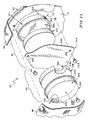
- FIG. 3 is an exploded perspective assembly view of the left-side ride-down pad of FIG. 2 showing that the ride-down pad is a multi-stage unit comprising (1) a first (inner) force dissipater including a first vessel (e.g., bag) formed to include a first air chamber and a forwardly facing first air-discharge port opening into the first air chamber and a first deformable support frame (e.g., cushion) sized to be located in the first air chamber and (2) a second (outer) force dissipater including a second vessel (e.g., bag) formed to include a second air chamber and a rearwardly facing second air-discharge port opening into the second air chamber and a second deformable support frame (e.g., cushion) sized to be located in the second air chamber;
- a first (inner) force dissipater including a first vessel (e.g., bag) formed to include a first air chamber and a forwardly facing first air-discharge port opening
- FIG. 4 is a side elevation view of the juvenile vehicle seat of FIG. 1 , with portions broken away, to reveal the left-side ride-down pad;
- FIG. 5 is a perspective view of the first (inner) and second (outer) force dissipaters included in the left-side ride-down pad while they are separated from one another and before they are mounted on the juvenile vehicle seat shown in FIG. 1 ;
- FIG. 6 is an enlarged sectional view taken along line 6 - 6 of FIG. 2 and of FIG. 4 showing placement of the left-side ride-down pad on an outer wall of a first side-wing panel of the headrest and placement of an interior pad on an inner wall of the first side-wing panel of the headrest;
- FIGS. 7-9 show a sequence in which the left-side ride-down pad is deformed in stages following sudden application of an external impact force to the second (outer) force dissipater to minimize the magnitude of a resulting force applied to a child seated in a juvenile vehicle seat including the left-side ride-down pad and thereby to minimize the g-load (acceleration) caused by the resulting force and experienced by the seated child;
- FIG. 7 shows a diagrammatic representation of a child at time t 0 before an external impact force is applied to the left-side ride-down pad mounted on the juvenile vehicle seat;
- FIG. 8 is a diagrammatic view similar to FIG. 7 at a later time t 1 after the external impact force has deformed the second bag and second cushion included in the second (outer) force dissipater;
- FIG. 9 is a diagrammatic view similar to FIGS. 7 and 8 at a still later time t 2 after the external impact force has also deformed the first bag and first cushion included in the first (inner) force dissipater;
- FIG. 10 is an exploded perspective view showing a ride-down pad kit in accordance with the present disclosure wherein the kit comprises four cushions associated with the first bag and four cushions associated with the second bag, each cushion provides a support frame in the air chamber of a companion bag and has a different deformation characteristic when exposed to an external impact force, and the deformability of each force dissipater can be varied by selecting a desired cushion from among the four available cushions and placing the selected cushion in a companion bag; to produce a force dissipater in accordance with the present disclosure;
- FIG. 11 is a perspective view of a child-restraint system including a juvenile vehicle seat and an energy-dissipation system in accordance with a second embodiment of the present disclosure
- FIG. 12 is an enlarged perspective view of the left-side ride-down pad and the first side wing of the headrest shown in FIG. 11 , with portions broken away;
- FIG. 13 is an exploded perspective assembly view of the left-side ride-down pad of FIG. 12 showing that the ride-down pad comprises, in sequence, from right to left, an inner shell formed to include a forwardly facing first air-discharge port, a first cushion, a partition, a second cushion, and an outer shell formed to include a rearwardly facing second air-discharge port and suggesting that the inner shell and the partition cooperate to form a first air chamber sized to receive the first cushion therein and that the outer shell and the partition cooperate to form a second air chamber sized to receive the second cushion therein;
- FIGS. 14-16 show a sequence in which the left-side ride-down pad is deformed following application of an external impact force to the second (outer) force dissipater to minimize the magnitude of a resulting force applied to a child seated in a juvenile vehicle seat carrying the left-side ride-down pad and thereby to minimize the g-load (acceleration) caused by the resulting force and experienced by the seated child;
- FIG. 14 shows a diagrammatic representation of a child at a time t 0 before an external impact force is applied to the left-side ride-down pad
- FIG. 15 is a diagrammatic view similar to FIG. 14 at a later time t 1 after the external impact force has deformed the outer shell and the second cushion included in a second (outer) force dissipater included in the energy-dissipation system of FIGS. 11-13 ;
- FIG. 16 is a diagrammatic view similar to FIGS. 14 and 15 at a still later time t 2 after the external impact force has also deformed the partition and first cushion included in a first (inner) force dissipater included in the energy-dissipation system of FIGS. 11-13 ;
- FIG. 17 is a perspective view similar to FIG. 12 showing an alternative location of the second air-discharge port of the second (outer) force dissipater relative to the first air-discharge port of the first (inner) force dissipater wherein the angular separation between the first and second air-discharge port is characterized by an included angle therebetween of about 72°;
- FIG. 18 is a perspective view similar to FIG. 17 showing that each of the first and second air-discharge ports is a cruciform opening defined by a cross-shaped pair of intersecting slits;
- FIG. 19 shows the four adjacent corner-shaped flaps separated from one another by the cross-shaped pair of intersecting slits spread apart to discharge air extant in a companion air chamber in response to application of an external force to the bag of the second (outer) force dissipater;
- FIG. 20 is an enlarged view taken along line 20 - 20 of FIG. 19 ;
- FIG. 21 is a perspective view of a child-restraint system in accordance with another embodiment of the disclosure showing multi-stage left-side and right-side ride-down pads wherein the left-side ride-down pad is coupled to an inner wall of a first side-wing panel of the headrest and the right-side ride-down pad is coupled to an inner wall of a second side-wing panel of the headrest; and
- FIG. 22 is a perspective view of a child-restraint system in accordance with yet another embodiment of the disclosure showing four multi-stage ride-down pads wherein a pad is carried on each of the outer and inner walls of the first side-wing panel of the headrest and a pad is also carried on each of the inner and outer walls of the opposite second side-wing panel of the headrest.
- One illustrative child-restraint system 11 comprises a juvenile vehicle seat 10 and an energy-dissipation system 16 coupled to juvenile vehicle seat 10 as suggested in FIG. 1 .
- juvenile vehicle seat 10 includes a seat bottom 12 and a seat back 14 extending upwardly from seat bottom 12 .
- a first illustrative energy-dissipation system 16 is coupled to seat back 14 of juvenile vehicle seat 10 as suggested in FIG. 1 .
- a second illustrative energy-dissipation system 116 is coupled to a seat back 14 of a juvenile vehicle seat 110 to form an illustrative child-restraint system 111 as suggested in FIG. 11 .
- FIGS. 17-22 Other illustrative energy-dissipation systems 616 , 716 , 816 , and 916 and components thereof are shown in FIGS. 17-22 . It is within the scope of this disclosure to mount energy-dissipation systems 16 or 116 of a child-restraint system on a juvenile seat or other device to dissipate energy transferred to such a seat or apparatus by means of an external impact force applied to the seat or apparatus.
- Each energy-dissipation system 16 , 116 , 616 , 716 , 816 , 916 comprises a ride-down pad that is designed to minimize the g-loads experienced by a child seated on seat bottom 12 of juvenile vehicle seat 10 during exposure of seat 10 to an external impact force.
- Multi-stage ride-down pads 21 , 22 in accordance with a first embodiment of the present disclosure are shown in FIGS. 1-9 .
- An illustrative kit 11 for making an illustrative ride-down pad is shown in FIG. 10 .
- Multi-stage ride-down pads 121 , 122 in accordance with a second embodiment of the present disclosure are shown in FIGS. 11-16 .
- Other embodiments are shown in FIGS. 21 and 22 . It is within the scope of this disclosure to provide a single-stage ride-down pad as suggested herein and for use in any of the designs shown, for example, in FIGS. 1 , 11 , 21 , and 22 .
- energy-dissipation system 16 comprises a left-side ride-down pad 21 , a right-side ride-down pad 22 , and a separate interior pad 23 .
- energy-dissipation system 16 is coupled to seat back 14 of juvenile vehicle seat 10 , and, in particular, to a headrest 26 included in seat back 14 .
- energy-dissipation system 16 is mounted on an outside portion of juvenile vehicle seat 10 as suggested, for example, in FIGS. 1 and 11 .
- seat back 12 of juvenile vehicle seat 10 includes a backrest 24 arranged to extend upwardly from seat bottom 12 and a headrest 26 coupled to backrest 24 .
- Left-side ride-down pad 21 is coupled to an outer wall of a first side-wing panel 31 included in headrest 26 .
- Right-side ride-down pad 22 is coupled to an outer wall of a second side-wing panel 32 included in headrest 26 .
- a somewhat C-shaped interior pad 23 is coupled to inner walls of first side-wing panel 31 and second side-wing panel 32 .
- Interior pad 23 is also coupled to an inner wall of a rear panel 30 located between and arranged to interconnect first and second side-wing panels 31 , 32 as suggested in FIG. 1 .
- interior pad 23 is arranged to surround partly the head of a child 100 seated in juvenile vehicle seat 10 to provide deformable padding for the child's head.
- ride-down pad similar to pads 21 , 22 (or other pads disclosed herein) elsewhere on juvenile vehicle seat 10 (e.g., outside torso area, inside head area, outside back area) or on another device in a zone on such seat or device exposed to external impact forces.
- Ride-down pads 321 , 322 in accordance with the present disclosure are mounted on inner walls of each of the first and second side-wing panels 331 , 332 of headrest 326 in an illustrative child restraint 311 having an energy-dissipation system 816 as shown in FIG. 21 .
- Ride-down pads 421 , 422 are mounted on outer walls of the first and second side-wing panels 431 , 432 of headrest 426 in an illustrative child restraint 411 shown in FIG. 22 while ride-down pads 441 , 442 are also mounted on inner walls of those first and second side-wing panels 431 , 432 to provide an energy-dissipation system 916 .
- ride-down pad 21 absorbs that transferred energy as suggested diagrammatically in FIGS. 7-9 to minimize the magnitude of a resulting force 200 applied to a child 100 seated in juvenile vehicle seat 10 during the collision.
- Ride-down pad 21 functions to minimize the g-loads (acceleration) experienced by child 100 seated on seat bottom 12 of juvenile vehicle seat 10 during exposure of seat 10 to external impact force 20 as suggested in FIGS. 7-9 .
- Ride-down pad 21 also functions to maximize the time interval (i.e., ride-down time) between the moment the impacting object strikes ride-down pad 21 to apply the external impact force and the moment that resulting force 200 reaches zero.
- interior pad 23 cooperates with left-side ride-down pad 21 to minimize the magnitude of resulting force 200 applied to child 100 during, for example, a collision.
- a portion 23 P of interior pad 23 is positioned to lie in a space provided between left-side ride-down pad 21 and child 100 .
- a portion 31 P of first side-wing panel 31 is positioned to lie in a space provided between left-side ride-down pad 21 and portion 23 P of interior pad 23 .
- left-side ride-down pad 21 is a multi-stage ride-down pad comprising a first (inner) force dissipater 41 and a second (outer) force dissipater 42 .
- each of first and second force dissipaters 41 , 42 comprises a vessel (such as a bag) containing a deformable support frame (such as a cushion).
- First and second force dissipaters 41 , 42 are stacked in series so that first force dissipater 42 lies in an inner position between second force dissipater 41 and first side-wing panel 31 of headrest 26 and so that second force dissipater 41 lies in an outer position in spaced-apart relation to first side-wing panel 31 . It is within the scope of this disclosure to configure left-side ride-down pad 21 as a single-stage ride-down pad comprising only first force dissipater 41 .
- First (inner) force dissipater 41 includes a first bag 51 and a first cushion 61 as suggested in FIGS. 2 and 3 .
- First bag 51 is formed to include a first air chamber 50 and a first air-discharge port 53 opening into first air chamber 50 .
- First cushion 61 is sized to fit into first air chamber 50 to leave, in the illustrated embodiment, some empty space 54 in first air chamber 50 after first cushion 61 is located in first air chamber 50 as suggested, for example, in FIG. 6 .
- First bag 51 can be formed using any suitable method using any suitable material.
- first bag 51 comprises a shell 511 formed to include first air-discharge port 53 and a closure 512 configured to be coupled to a rim 513 included in shell 511 to define first air chamber 50 between shell 511 and closure 512 .
- first air-discharge port 53 is an aperture as suggested in FIG. 2
- first air-discharge port 212 is an aperture as suggested in FIG. 12
- Second (outer) force dissipater 42 includes a second bag 72 and a second cushion 62 as suggested in FIGS. 2 and 3 .
- Second bag 72 is formed to include a second air chamber 70 and a second air-discharge port 73 opening into second air chamber 70 .
- Second cushion 62 is sized to fit into second air chamber 70 to leave, in the illustrated embodiment, some empty space 55 in second air chamber 70 after second cushion 62 is located in second air chamber 70 as suggested, for example, in FIG. 6 .
- Second bag 72 can be formed using any suitable method using any suitable material.
- second bag 72 comprises a shell 721 formed to include second air-discharge port 73 and a closure 722 configured to be coupled to a rim 723 included in shell 721 to define second air chamber 70 between shell 721 and closure 722 .
- second air-discharge port is an aperture as suggested in FIG. 2
- second air-discharge port 224 is an aperture as suggested in FIG. 12
- Cushions 61 , 62 are illustrative examples of deformable support frames that are located in air chambers formed in bags 51 , 72 or other vessels in accordance with the present disclosure.
- a deformable support frame as disclosed herein provides means for supporting the vessel (e.g., bag) to maintain at least a predetermined volume of air (or other fluid) in the air chamber until the vessel is deformed when exposed to an external impact force. The vessel is thus supported by the deformable support frame so that the vessel does not deform too quickly and deforms at a rate that allows the vessel to absorb external energy associated with the external impact force.
- the deformable support frame is a cushion that is sized to fill most of the air chamber in a companion vessel.
- Each of bags 51 , 72 includes an air chamber 50 , 70 configured to store a predetermined volume of air and an air-discharge port configured to provide means for discharging a metered volume of air from that air chamber in response to application of an external impact force 20 to such bag 80 that the external energy associated with external impact force 20 is absorbed to minimize g-loads experienced by a child seated on the seat bottom of a juvenile vehicle seat.
- each of force dissipaters 41 , 42 included in left-side ride-down pad 21 is substantially undeformed at time t 0 before any collision involving juvenile vehicle seat 10 takes place.
- Interior pad 23 is also substantially undeformed at time t 0 .
- external impact force 20 acts to deform first bag 51 and first cushion 61 included in first (inner) force dissipater 41 .
- Some of the air extant in first air chamber 50 is exhausted through first air-discharge port 53 as discharged air 55 as suggested in FIG. 9 .
- juvenile vehicle seat 10 has moved relative to child 100 to cause a portion (e.g., the head) of child 100 to contact and deform portion 23 P of interior pad 23 .
- First (inner) and second (outer) force dissipaters 41 , 42 and interior pad 23 cooperate to absorb energy transferred by external impact force 20 to minimize resulting force 200 applied to child 100 seated in juvenile vehicle seat 10 .
- This energy absorption feature minimizes the g-loads (acceleration) experienced by child 100 and also maximizes the ride-down time between the first strike of an impacting object on second (outer) force dissipater 42 of left-side ride-down pad 21 and the moment that resulting force 200 reaches zero.
- first (inner) and second (outer) force dissipaters 41 , 42 are oriented relative to one another to cause first air-discharge port 53 of first force dissipater 41 to face (e.g., forwardly) in a first direction 101 and second air-discharge port 73 of second force dissipater 42 to face (e.g., rearwardly) in an opposite second direction 102 as suggested in FIGS. 2 and 3 .
- air-discharge ports 53 , 73 are separated from one another by an effective included angle of about 180° as suggested in FIGS. 2 , 3 , and 6 .
- first (inner) and second (outer) force dissipaters 641 , 642 included in energy-dissipation system 616 are oriented relative to one another to cause first air-discharge port 653 of first force dissipater 641 to face (e.g., forwardly) in first direction 101 and second air-discharge port 673 of second force dissipater 642 to face (e.g., forwardly and upwardly) in a second direction 172 .
- air-discharge ports 653 , 673 are separated from one another by an effective included angle of about 72° as suggested in FIG. 17 .
- any suitable means may be used to retain first and second force dissipaters 41 , 42 in the mounted positions shown in FIGS. 2 , 4 , and 6 .
- (e.g., hook-and-loop) fasteners 44 and 46 are used as suggested in FIGS. 5 and 6 .
- Fastener 44 retains second (outer) force dissipater 42 in a fixed position relative to first (inner) force dissipater 41 when coupled to both of first and second force dissipaters 41 , 42 as suggested in FIG. 6 .
- Fastener 46 retains first (inner) force dissipater 41 in a fixed position relative to first side-wing panel 31 of headrest 26 when coupled to both of first force dissipater 41 and first side-wing panel 31 as suggested in FIG. 6 .
- each of air bags 51 , 72 is made of a plastics material such as polyvinyl chloride (PVC) or nylon.
- PVC polyvinyl chloride
- each of bags 51 , 72 is made of a sheet of PVC or nylon and has a nominal thickness of about 0.030 inch (0.076 centimeters).
- the volume of each bag 51 , 72 is about 28.27 cubic inches (463.33 cubic centimeters) and the diameter of each round air-discharge port 53 , 73 is about three-sixteenths inch (0.476 cm).
- a single round air-discharge port 53 could be replaced by two or mare smaller side-by-side or adjacent air-discharge ports (not shown) having a combined area about equivalent to the area of the single round air-discharge port 53 . It is within the scope of this disclosure to use a variety of hole shapes and sizes such as a cruciform shape shown in FIGS. 18-20 .
- the number of air-discharge ports 53 , 73 varies from two to four per bag depending upon the material used to form cushions 61 , 62 .
- Each of first and second cushions 61 , 62 and interior pad 23 is configured to deform at about a predetermined rate when exposed to a predetermined external impact force 20 .
- Each bag 51 , 72 contains a volume of air that is discharged at a metered rate when the bag 51 or 72 is exposed to an external impact force 20 .
- energy-dissipation system 16 comprising ride-down pad 21 and interior pad 23 is programmable to yield an applied g-load to child 100 in seat 10 over a specified ride-down time in response to exposure of ride-down pad 21 to a specified external impact force 20 .
- cushions 61 , 62 out of fluid foam, micro-spheres, gels, liquids, crushable designed material, foams (e.g., Extruded Polymer Products (EPP), Extra Cellular Polymer Substances (EPS), Polyurethane (PU), Thermoplastic Elastomer (TPE), Polypropylene (PP), etc.), polystyrene (PS), viscoelastic polymener, fluidized air, air, or combinations of the foregoing materials.
- foams e.g., Extruded Polymer Products (EPP), Extra Cellular Polymer Substances (EPS), Polyurethane (PU), Thermoplastic Elastomer (TPE), Polypropylene (PP), etc.
- PS polystyrene
- viscoelastic polymener fluidized air, air, or combinations of the foregoing materials.
- an outer cover 48 is coupled to headrest 26 and arranged to cover each of left-side and right-side ride-down pads 21 , 22 .
- Outer cover 48 also functions to dissipate energy associated with external impact forces 20 and to protect first and second force dissipaters 41 , 42 from damage.
- a ride-down pad kit 11 in accordance with the present disclosure is shown, for example, in FIG. 10 .
- any of an assortment of deformable support frames e.g., cushions 61 , 610 , 611 , 612
- first air chamber 50 associated with first force dissipater 41 to change the energy-dissipation (i.e., deformation) rate of first force dissipater 41 .
- any of cushions 62 , 620 , 621 , 622 could be placed in second air chamber 70 associated with second force dissipater 42 to change the energy-dissipation (i.e., deformation) rate of second force dissipater 42 .
- Each cushion is configured to exhibit a characteristic deformation rate in response to a specified external impact force. It is within the scope of this disclosure to vary the number and kind of cushions placed in an air chamber.
- an energy-dissipation system 116 in accordance with a second embodiment of the present disclosure comprises a left-side ride-down pad 121 , a right-side ride-down pad 122 , and a separate interior pad 23 .
- energy-dissipation system 116 is coupled to seat back 14 , and, in particular, to a headrest 26 included in seat back 14 of juvenile vehicle seat 110 .
- ride-down pad 121 absorbs or otherwise dissipates that transferred energy as suggested diagrammatically in FIGS. 14-16 to minimize the magnitude of a resulting force 200 applied to a child 100 seated in juvenile vehicle seat 10 during the collision.
- Ride-down pad 121 functions to minimize the g-loads (acceleration) experienced by a child seated on seat bottom 12 of juvenile vehicle seat 110 during exposure of child restraint to external impact force 20 .
- Ride-down pad 121 also functions to maximize the time interval (i.e., ride-down time) between the moment the impacting object strikes ride-down pad 121 to apply the external impact force and the moment that resulting force 200 reaches zero.
- left-side ride-down pad 121 comprises, in sequence, from right to left, an inner shell 210 formed to include a first air-discharge port 212 , a first cushion 214 , a partition 216 , a second cushion 218 , and an outer shell 222 formed to include a second air-discharge port 224 .
- Right-side ride-down pad 122 has a similar construction.
- An inner surface 216 i of partition 216 mates with inner shell 210 to form a first air chamber 226 therebetween as suggested in FIGS. 12 and 13 .
- First cushion 214 is located in first air chamber 226 to cooperate with inner shell 210 and inner surface 216 i of partition 216 to establish a first (inner) force dissipater 141 included in left-side ride-down pad 122 .
- inner shell 210 includes a dome 211 and a rim 213 appended to a perimeter edge of dome 211 as suggested in FIG. 13 . Rim 213 mates with inner surface 216 i of partition 216 to form a first (inner) bag.
- An outer surface 216 o of partition 216 mates with outer shell 222 to form a second air chamber 228 therebetween as suggested in FIGS. 12 and 13 .
- Second cushion 218 is located in second air chamber 228 to cooperate with outer shell 222 and outer surface 216 o of partition 216 to establish a second (outer) force dissipater 142 included in left-side ride-down pad 121 .
- outer shell 222 includes a dome 223 and a rim 225 appended to a perimeter edge of dome 223 as suggested in FIGS. 12 and 13 .
- Rim 225 mates with outer surface 216 o of partition 216 to form a second (outer) bag.
- each of force dissipaters 141 , 142 included in left-side ride-down pad 121 is substantially undeformed at time t 0 before any collision involving juvenile vehicle seat 110 takes place.
- Interior pad 23 is also substantially undeformed at time t 0 .
- external impact force 20 acts to deform partition 216 and inner shell 210 and first cushion 214 .
- Air extant in first air chamber 226 is exhausted through first air-discharge port 212 at a metered rate as discharged air 230 as suggested in FIG. 16 .
- juvenile vehicle seat 110 has moved relative to child 100 to cause a portion (e.g., the head) of child 100 to contact and deform a portion of interior pad 23 .
- First (inner) and second (outer) force dissipaters 141 , 142 and interior pad 23 cooperate to absorb energy transferred by external impact force 20 to minimize resulting force 200 applied to child 100 seated in juvenile vehicle seat 110 .
- This energy absorption feature minimizes the g-loads (acceleration) experienced by child 100 and also maximizes the ride-down time between the first strike of an impacting object on second (outer) force dissipater 142 of left-side ride-down pad 121 and the moment that resulting force 200 reaches zero.
- first (inner) and second (outer) force dissipaters 141 , 142 are oriented relative to one another to cause first air-discharge port 212 of first force dissipater 141 to face (e.g., forwardly) in a first direction 101 and second air-discharge port 224 of second force dissipater 142 to face (e.g., rearwardly) in an opposite second direction 102 as suggested in FIGS. 12 and 13 .
- air-discharge ports 212 , 224 are separated from one another by an effective angle of about 180° as suggested in FIGS. 12 and 13 .
- any suitable means may be used to retain first and second force dissipaters 141 , 142 in the mounted positions shown in FIGS. 11-16 .
- fasteners 251 , 252 , and 253 are used as suggested in FIG. 13 to retain first and second force dissipaters 141 , 142 in a fixed position on first side-wing 31 of headrest 26 .
- Each fastener 251 - 233 passes through one of the three fastener-receiving apertures 254 formed in an outer portion of partition 216 and mates with first side-wing panel 31 of headrest 26 as suggested in FIGS. 12 and 13 .
- an outer cover 48 is coupled to headrest 26 and arranged to cover each of left-side and right-side ride-down pads 121 , 122 .
- Outer cover 48 also functions to dissipate energy associated with external impact forces 20 and to protect first and second force dissipaters 141 , 142 from damage.
- a first (inner) force dissipater 741 includes a first air-discharge port 753 and a second (outer) force dissipater 742 includes a second air-discharge port 773 .
- Each of air-discharge ports 753 , 773 comprises a slit 501 or 502 .
- each of air-discharge ports 753 , 773 is a cruciform opening defined by a cross-shaped pair of orthogonal intersecting slits 501 , 502 . As suggested in FIGS.
- four adjacent corner-shaped flaps 401 , 402 , 403 , 404 cooperate to define slits 501 , 502 of air-discharge port 753 and four other adjacent corner-shaped flaps 411 , 412 , 413 , 414 cooperate to define slits 501 , 502 of air-discharge port 773 .
- Four adjacent corner-shaped flaps 411 , 412 , 413 , 414 separated from one another by the cross-shaped pair of intersecting slits 501 , 502 are spread apart as shown in FIG. 19 to discharge air extant in a companion air chamber in response to application of an external force 20 to the bag of the second (outer) force dissipater 742 .
Abstract
Description
Claims (25)
Priority Applications (3)
| Application Number | Priority Date | Filing Date | Title |
|---|---|---|---|
| US12/328,376 US7744154B2 (en) | 2008-07-30 | 2008-12-04 | Energy-dissipation system |
| US12/512,798 US8061768B2 (en) | 2008-07-30 | 2009-07-30 | Energy-dissipation system |
| US12/788,402 US7850234B2 (en) | 2008-07-30 | 2010-05-27 | Energy-dissipation system |
Applications Claiming Priority (2)
| Application Number | Priority Date | Filing Date | Title |
|---|---|---|---|
| US8488908P | 2008-07-30 | 2008-07-30 | |
| US12/328,376 US7744154B2 (en) | 2008-07-30 | 2008-12-04 | Energy-dissipation system |
Related Child Applications (2)
| Application Number | Title | Priority Date | Filing Date |
|---|---|---|---|
| US12/512,798 Continuation-In-Part US8061768B2 (en) | 2008-07-30 | 2009-07-30 | Energy-dissipation system |
| US12/788,402 Continuation US7850234B2 (en) | 2008-07-30 | 2010-05-27 | Energy-dissipation system |
Publications (2)
| Publication Number | Publication Date |
|---|---|
| US20100026064A1 US20100026064A1 (en) | 2010-02-04 |
| US7744154B2 true US7744154B2 (en) | 2010-06-29 |
Family
ID=41607572
Family Applications (2)
| Application Number | Title | Priority Date | Filing Date |
|---|---|---|---|
| US12/328,376 Active US7744154B2 (en) | 2008-07-30 | 2008-12-04 | Energy-dissipation system |
| US12/788,402 Active US7850234B2 (en) | 2008-07-30 | 2010-05-27 | Energy-dissipation system |
Family Applications After (1)
| Application Number | Title | Priority Date | Filing Date |
|---|---|---|---|
| US12/788,402 Active US7850234B2 (en) | 2008-07-30 | 2010-05-27 | Energy-dissipation system |
Country Status (16)
| Country | Link |
|---|---|
| US (2) | US7744154B2 (en) |
| EP (1) | EP2307241B1 (en) |
| JP (1) | JP2010531274A (en) |
| CN (2) | CN103770675B (en) |
| AU (1) | AU2008311740B2 (en) |
| BR (1) | BRPI0805813B1 (en) |
| CA (1) | CA2701307C (en) |
| DK (1) | DK2307241T3 (en) |
| EA (1) | EA016130B1 (en) |
| ES (1) | ES2452467T3 (en) |
| HK (1) | HK1152279A1 (en) |
| IL (1) | IL198278A (en) |
| NZ (1) | NZ576263A (en) |
| PL (1) | PL2307241T3 (en) |
| PT (1) | PT2307241E (en) |
| WO (1) | WO2010014122A1 (en) |
Cited By (22)
| Publication number | Priority date | Publication date | Assignee | Title |
|---|---|---|---|---|
| US20090224580A1 (en) * | 2008-03-05 | 2009-09-10 | Cosco Management, Inc. | Juvenile motion-inhibitor system |
| US20100026059A1 (en) * | 2008-07-30 | 2010-02-04 | Cosco Management, Inc. | Energy-dissipation system |
| US20100171348A1 (en) * | 2006-12-14 | 2010-07-08 | Arjuna Indraesewaran Rajasingham | Occupant support system |
| US20100231012A1 (en) * | 2008-07-30 | 2010-09-16 | Cosco Management, Inc. | Energy-dissipation system |
| US20100295270A1 (en) * | 2009-05-20 | 2010-11-25 | Cosco Management, Inc. | Energy-dissipation system |
| US20100295343A1 (en) * | 2009-05-20 | 2010-11-25 | Cosco Management, Inc. | Energy-dissipation system |
| US20100295341A1 (en) * | 2009-05-20 | 2010-11-25 | Cosco Management, Inc. | Energy-dissipation system |
| US20100295344A1 (en) * | 2009-05-20 | 2010-11-25 | Cosco Management, Inc. | Energy-dissipation system |
| US20100295345A1 (en) * | 2009-05-20 | 2010-11-25 | Cosco Management, Inc. | Energy-dissipation system |
| US20100295346A1 (en) * | 2009-05-20 | 2010-11-25 | Cosco Management, Inc. | Energy-dissipation system |
| US20100295342A1 (en) * | 2009-05-20 | 2010-11-25 | Cosco Management, Inc. | Energy-dissipation system |
| US20100295347A1 (en) * | 2009-05-20 | 2010-11-25 | Cosco Management, Inc. | Energy-dissipation system |
| US8690237B2 (en) | 2012-06-07 | 2014-04-08 | Graco Children's Products Inc. | Child car seat and headrest with side impact energy absorption |
| WO2014053009A1 (en) * | 2012-10-01 | 2014-04-10 | Infa-Secure Pty Ltd | Energy attenuation system for a child safety seat |
| US8863320B2 (en) | 2013-01-18 | 2014-10-21 | Windpact, Inc. | Impact absorbing apparatus |
| US9221366B2 (en) | 2011-06-02 | 2015-12-29 | Dorel Juvenile Group, Inc. | Energy-dissipation system |
| US9315126B2 (en) | 2012-06-01 | 2016-04-19 | Dorel Juvenile Group, Inc. | Energy-dissipation system |
| US9669739B1 (en) | 1999-11-08 | 2017-06-06 | Arjuna Indraeswaran Rajasingham | Vehicle occupant support |
| US10046676B2 (en) | 2015-07-23 | 2018-08-14 | Dorel Juvenile Group, Inc. | Child restraint with energy management system |
| USRE47971E1 (en) | 2012-06-01 | 2020-05-05 | Dorel Juvenile Group, Inc. | Energy-dissipation system |
| US10780857B1 (en) * | 2006-12-14 | 2020-09-22 | Arjuna Indraeswaran Rajasingham | Vehicle occupant support |
| US11364822B1 (en) * | 2005-12-19 | 2022-06-21 | Arjuna Indraeswaran Rajasingham | Vehicle occupant support |
Families Citing this family (21)
| Publication number | Priority date | Publication date | Assignee | Title |
|---|---|---|---|---|
| DE102011003650A1 (en) | 2011-02-04 | 2012-08-09 | Takata-Petri Ag | Energy absorbing deformation structure |
| DE102011016959A1 (en) * | 2011-04-13 | 2012-10-18 | Sitech Sitztechnik Gmbh | Headrest with an autoreactive framework structure |
| CN102390301B (en) * | 2011-09-06 | 2013-10-30 | 张英 | Lightning seat of mine resistant ambush protected vehicle |
| ES2538327T3 (en) * | 2011-09-13 | 2015-06-19 | BRITAX RÖMER Kindersicherheit GmbH | Child safety seat for vehicles |
| EP3858663B1 (en) | 2013-07-16 | 2023-03-22 | BRITAX RÖMER Kindersicherheit GmbH | Child safety seat |
| CN204136815U (en) * | 2013-09-13 | 2015-02-04 | 明门(中国)幼童用品有限公司 | Feet shock absorber and safety chair seats of car |
| NO338505B1 (en) * | 2014-09-05 | 2016-08-29 | Torgersen Hans & Soenn | Child safety seat |
| CN204605583U (en) | 2015-02-06 | 2015-09-02 | 宝钜(中国)儿童用品有限公司 | Child safety seat |
| US11090216B2 (en) * | 2015-07-30 | 2021-08-17 | Eva Medtec, Inc. | Therapeutic massage system |
| US10118510B2 (en) * | 2015-12-01 | 2018-11-06 | Evenflo Company, Inc. | Impact protection for child car seat |
| CN106080309A (en) * | 2016-08-03 | 2016-11-09 | 苏州逗乐儿童用品有限公司 | Child safety seat |
| US10377274B2 (en) * | 2016-08-25 | 2019-08-13 | Dorel Juvenile Group, Inc. | Infant carrier |
| CN107826005A (en) * | 2017-12-08 | 2018-03-23 | 清华大学苏州汽车研究院(相城) | A kind of lateral side protection and child safety seat for child safety seat |
| DE202017107887U1 (en) | 2017-12-22 | 2018-01-12 | Cybex Gmbh | Child seat for attachment to a motor vehicle seat |
| CN110126773B (en) * | 2018-02-02 | 2022-08-19 | 宝钜瑞士股份有限公司 | Automatic-ejecting side-impact protection device |
| US10676085B2 (en) * | 2018-04-11 | 2020-06-09 | Aurora Innovation, Inc. | Training machine learning model based on training instances with: training instance input based on autonomous vehicle sensor data, and training instance output based on additional vehicle sensor data |
| CN108674265B (en) * | 2018-07-12 | 2024-02-27 | 浙江博安母婴用品有限公司 | Telescopic side protection airbag of child safety seat |
| JP7338989B2 (en) * | 2019-03-01 | 2023-09-05 | 株式会社小松製作所 | Driver's cab and work vehicle |
| CN110641330A (en) * | 2019-10-09 | 2020-01-03 | 浙江感恩科技股份有限公司 | Side collision prevention structure of child safety seat |
| CN113386639A (en) * | 2020-03-13 | 2021-09-14 | 宝钜瑞士股份有限公司 | Child safety seat |
| EP4011691A1 (en) * | 2020-12-14 | 2022-06-15 | George TFE SCP | Child safety seat |
Citations (22)
| Publication number | Priority date | Publication date | Assignee | Title |
|---|---|---|---|---|
| US4899961A (en) | 1988-06-28 | 1990-02-13 | The Boeing Company | Inflatable, lateral head restraint |
| US4919483A (en) | 1989-06-16 | 1990-04-24 | Horkey Gregory R | Collapsible and reformable headrest for vehicles |
| US5292175A (en) * | 1992-09-04 | 1994-03-08 | Babystar | Inflatable child vehicle seat |
| US5292176A (en) * | 1992-09-04 | 1994-03-08 | Babystar | Inflatable child vehicle seat |
| US5335968A (en) * | 1991-10-16 | 1994-08-09 | Sheridan Peter A J | Child's booster seat |
| US5567015A (en) | 1995-03-01 | 1996-10-22 | Arias; Antonio | Inflatable headrest apparatus |
| US5881395A (en) | 1993-07-08 | 1999-03-16 | Donzis; Byron A | Impact absorbing pad |
| US20020153753A1 (en) | 2000-08-31 | 2002-10-24 | Kenzou Kassai | Heat protective structure of nursery equipment, head protective pad, and infant safety seat for car |
| US6485101B2 (en) | 1998-01-27 | 2002-11-26 | Aprica Kassai Kabushikikaisha | Child seat with movable side head guards |
| US6519780B2 (en) | 2001-04-04 | 2003-02-18 | Edward L. Goodwin | Air-holding protective foam pad construction |
| US7125073B2 (en) | 2003-02-25 | 2006-10-24 | Takata Corporation | Child seat |
| US20070085394A1 (en) * | 2005-10-13 | 2007-04-19 | Yang Jen S | Inflatable child safety seat |
| US7232182B2 (en) | 2003-02-25 | 2007-06-19 | Takata Corporation | Child seat |
| US7234771B2 (en) | 2003-10-23 | 2007-06-26 | Britax Child Safety, Inc. | Child safety seat with adjustable head restraint |
| US7246853B2 (en) | 2004-06-29 | 2007-07-24 | Kidnetik Corp. | Child restraint apparatus for a vehicle |
| US7293828B2 (en) * | 2003-06-12 | 2007-11-13 | Takata Corporation | Child seat with deployable side airbags |
| US20080258518A1 (en) | 2007-04-23 | 2008-10-23 | Jane, S.A. | Collision safety device being applicable to infant seats |
| WO2009076514A2 (en) | 2007-12-12 | 2009-06-18 | Britax Child Safety, Inc. | Child restraint apparatus for vehicle |
| US20090179469A1 (en) * | 2008-01-14 | 2009-07-16 | Eric Bass | Head and Body Protection System for a Child Safety Seat |
| US20090179470A1 (en) * | 2008-01-14 | 2009-07-16 | Eric Bass | Head and body protection child safety seat |
| US20090256404A1 (en) * | 2008-04-15 | 2009-10-15 | Britax Child Safety, Inc. | Child seat having a crush zone |
| US20100019554A1 (en) * | 2008-07-22 | 2010-01-28 | Britax Child Safety, Inc. | Juvenile seating with resilient side impact protection |
Family Cites Families (10)
| Publication number | Priority date | Publication date | Assignee | Title |
|---|---|---|---|---|
| US4642814A (en) | 1985-11-01 | 1987-02-17 | Godfrey Jerry W | Athletic padding |
| US5235715A (en) | 1987-09-21 | 1993-08-17 | Donzis Byron A | Impact asborbing composites and their production |
| DE10156621C1 (en) * | 2001-11-17 | 2002-11-21 | Thomas Hausmann | Child seat, for automobile or aircraft, has foam-filled inflatable cushioning elements allowing fitting to each child |
| DE20308464U1 (en) * | 2002-06-20 | 2003-08-21 | Keiper Recaro Gmbh Co | Car safety seat for baby, comprising separately movable backrest and seat, for being also used as portable cot |
| JP2004314800A (en) * | 2003-04-16 | 2004-11-11 | Takata Corp | Child seat |
| DE202005011742U1 (en) * | 2005-07-27 | 2005-11-03 | Curt Würstl Vermögensverwaltungs-Gmbh & Co. Kg | Child safety seat for use in motor vehicle, has side panels tilted into protection position from where child looks through window and restored to usage position by application of forces on panels |
| DE102005046651B4 (en) * | 2005-09-29 | 2022-03-31 | Volkswagen Ag | Energy absorption element, in particular deformation element, as a safety device for motor vehicles |
| US7774866B2 (en) | 2006-02-16 | 2010-08-17 | Xenith, Llc | Impact energy management method and system |
| DE202006010876U1 (en) * | 2006-07-10 | 2006-09-28 | Takata-Petri Ag | Energy absorber for motor vehicle seat or child seat, has covering of flexible material wrapped around foam core |
| US7744154B2 (en) * | 2008-07-30 | 2010-06-29 | Cosco Management, Inc. | Energy-dissipation system |
-
2008
- 2008-12-04 US US12/328,376 patent/US7744154B2/en active Active
- 2008-12-18 DK DK08840784.6T patent/DK2307241T3/en active
- 2008-12-18 BR BRPI0805813A patent/BRPI0805813B1/en active IP Right Grant
- 2008-12-18 NZ NZ576263A patent/NZ576263A/en unknown
- 2008-12-18 ES ES08840784.6T patent/ES2452467T3/en active Active
- 2008-12-18 PT PT88407846T patent/PT2307241E/en unknown
- 2008-12-18 CA CA2701307A patent/CA2701307C/en active Active
- 2008-12-18 WO PCT/US2008/087382 patent/WO2010014122A1/en active Application Filing
- 2008-12-18 AU AU2008311740A patent/AU2008311740B2/en active Active
- 2008-12-18 EA EA200900559A patent/EA016130B1/en unknown
- 2008-12-18 EP EP08840784.6A patent/EP2307241B1/en active Active
- 2008-12-18 PL PL08840784T patent/PL2307241T3/en unknown
- 2008-12-18 JP JP2010523207A patent/JP2010531274A/en active Pending
-
2009
- 2009-01-12 CN CN201410019391.1A patent/CN103770675B/en active Active
- 2009-01-12 CN CN200910000150.1A patent/CN101638065B/en active Active
- 2009-04-21 IL IL198278A patent/IL198278A/en active IP Right Grant
-
2010
- 2010-05-27 US US12/788,402 patent/US7850234B2/en active Active
-
2011
- 2011-06-21 HK HK11106396.4A patent/HK1152279A1/en unknown
Patent Citations (25)
| Publication number | Priority date | Publication date | Assignee | Title |
|---|---|---|---|---|
| US4899961A (en) | 1988-06-28 | 1990-02-13 | The Boeing Company | Inflatable, lateral head restraint |
| US4919483A (en) | 1989-06-16 | 1990-04-24 | Horkey Gregory R | Collapsible and reformable headrest for vehicles |
| US5335968A (en) * | 1991-10-16 | 1994-08-09 | Sheridan Peter A J | Child's booster seat |
| US5292175A (en) * | 1992-09-04 | 1994-03-08 | Babystar | Inflatable child vehicle seat |
| US5292176A (en) * | 1992-09-04 | 1994-03-08 | Babystar | Inflatable child vehicle seat |
| US5881395A (en) | 1993-07-08 | 1999-03-16 | Donzis; Byron A | Impact absorbing pad |
| US5567015A (en) | 1995-03-01 | 1996-10-22 | Arias; Antonio | Inflatable headrest apparatus |
| US6485101B2 (en) | 1998-01-27 | 2002-11-26 | Aprica Kassai Kabushikikaisha | Child seat with movable side head guards |
| US20020153753A1 (en) | 2000-08-31 | 2002-10-24 | Kenzou Kassai | Heat protective structure of nursery equipment, head protective pad, and infant safety seat for car |
| US6519780B2 (en) | 2001-04-04 | 2003-02-18 | Edward L. Goodwin | Air-holding protective foam pad construction |
| US7232182B2 (en) | 2003-02-25 | 2007-06-19 | Takata Corporation | Child seat |
| US7125073B2 (en) | 2003-02-25 | 2006-10-24 | Takata Corporation | Child seat |
| US7293828B2 (en) * | 2003-06-12 | 2007-11-13 | Takata Corporation | Child seat with deployable side airbags |
| US7234771B2 (en) | 2003-10-23 | 2007-06-26 | Britax Child Safety, Inc. | Child safety seat with adjustable head restraint |
| US7246853B2 (en) | 2004-06-29 | 2007-07-24 | Kidnetik Corp. | Child restraint apparatus for a vehicle |
| US20070252418A1 (en) | 2004-06-29 | 2007-11-01 | Harcourt John A | Child restraint apparatus for a vehicle |
| US20070085394A1 (en) * | 2005-10-13 | 2007-04-19 | Yang Jen S | Inflatable child safety seat |
| US20080258518A1 (en) | 2007-04-23 | 2008-10-23 | Jane, S.A. | Collision safety device being applicable to infant seats |
| WO2009076514A2 (en) | 2007-12-12 | 2009-06-18 | Britax Child Safety, Inc. | Child restraint apparatus for vehicle |
| US20090152913A1 (en) | 2007-12-12 | 2009-06-18 | Britax Child Safety, Inc. | Child restraint apparatus for vehicle |
| US20090179469A1 (en) * | 2008-01-14 | 2009-07-16 | Eric Bass | Head and Body Protection System for a Child Safety Seat |
| US20090179470A1 (en) * | 2008-01-14 | 2009-07-16 | Eric Bass | Head and body protection child safety seat |
| US7654613B2 (en) * | 2008-01-14 | 2010-02-02 | Eric Bass | Head and body protection system for a child safety seat |
| US20090256404A1 (en) * | 2008-04-15 | 2009-10-15 | Britax Child Safety, Inc. | Child seat having a crush zone |
| US20100019554A1 (en) * | 2008-07-22 | 2010-01-28 | Britax Child Safety, Inc. | Juvenile seating with resilient side impact protection |
Non-Patent Citations (1)
| Title |
|---|
| International Search Report dated Feb. 13, 2009, for International Application No. PCT/US2008/087382. |
Cited By (36)
| Publication number | Priority date | Publication date | Assignee | Title |
|---|---|---|---|---|
| US9669739B1 (en) | 1999-11-08 | 2017-06-06 | Arjuna Indraeswaran Rajasingham | Vehicle occupant support |
| US11364822B1 (en) * | 2005-12-19 | 2022-06-21 | Arjuna Indraeswaran Rajasingham | Vehicle occupant support |
| US20100171348A1 (en) * | 2006-12-14 | 2010-07-08 | Arjuna Indraesewaran Rajasingham | Occupant support system |
| US10780857B1 (en) * | 2006-12-14 | 2020-09-22 | Arjuna Indraeswaran Rajasingham | Vehicle occupant support |
| US8864229B2 (en) * | 2006-12-14 | 2014-10-21 | Arjuna Indraesewaran Rajasingham | Occupant support system |
| US8104829B2 (en) | 2008-03-05 | 2012-01-31 | Cosco Management, Inc. | Juvenile motion-inhibitor system |
| US20090224580A1 (en) * | 2008-03-05 | 2009-09-10 | Cosco Management, Inc. | Juvenile motion-inhibitor system |
| US7850234B2 (en) * | 2008-07-30 | 2010-12-14 | Cosco Management, Inc. | Energy-dissipation system |
| US20100026059A1 (en) * | 2008-07-30 | 2010-02-04 | Cosco Management, Inc. | Energy-dissipation system |
| US20100231012A1 (en) * | 2008-07-30 | 2010-09-16 | Cosco Management, Inc. | Energy-dissipation system |
| US8061768B2 (en) * | 2008-07-30 | 2011-11-22 | Cosco Management, Inc. | Energy-dissipation system |
| US8056971B2 (en) | 2009-05-20 | 2011-11-15 | Cosco Management, Inc. | Energy-dissipation system |
| US20100295345A1 (en) * | 2009-05-20 | 2010-11-25 | Cosco Management, Inc. | Energy-dissipation system |
| US7959223B2 (en) | 2009-05-20 | 2011-06-14 | Cosco Management, Inc. | Energy-dissipation system |
| US8029054B2 (en) | 2009-05-20 | 2011-10-04 | Cosco Management, Inc. | Energy-dissipation system |
| US8038209B2 (en) | 2009-05-20 | 2011-10-18 | Cosco Management, Inc. | Energy-dissipation system |
| US8052210B2 (en) * | 2009-05-20 | 2011-11-08 | Cosco Management, Inc. | Energy-dissipation system |
| US8056972B2 (en) | 2009-05-20 | 2011-11-15 | Cosco Management, Inc. | Energy-dissipation system |
| US20100295342A1 (en) * | 2009-05-20 | 2010-11-25 | Cosco Management, Inc. | Energy-dissipation system |
| US20100295346A1 (en) * | 2009-05-20 | 2010-11-25 | Cosco Management, Inc. | Energy-dissipation system |
| US20100295341A1 (en) * | 2009-05-20 | 2010-11-25 | Cosco Management, Inc. | Energy-dissipation system |
| US8128165B2 (en) * | 2009-05-20 | 2012-03-06 | Cosco Management, Inc. | Energy-dissipation system |
| US20100295343A1 (en) * | 2009-05-20 | 2010-11-25 | Cosco Management, Inc. | Energy-dissipation system |
| US20100295270A1 (en) * | 2009-05-20 | 2010-11-25 | Cosco Management, Inc. | Energy-dissipation system |
| US20100295347A1 (en) * | 2009-05-20 | 2010-11-25 | Cosco Management, Inc. | Energy-dissipation system |
| US20100295344A1 (en) * | 2009-05-20 | 2010-11-25 | Cosco Management, Inc. | Energy-dissipation system |
| US9221366B2 (en) | 2011-06-02 | 2015-12-29 | Dorel Juvenile Group, Inc. | Energy-dissipation system |
| US9592752B2 (en) | 2011-06-02 | 2017-03-14 | Dorel Juvenile Group, Inc. | Energy-dissipation system |
| US11083237B2 (en) | 2011-10-14 | 2021-08-10 | Windpact, Inc. | Impact absorbing apparatus |
| US9315126B2 (en) | 2012-06-01 | 2016-04-19 | Dorel Juvenile Group, Inc. | Energy-dissipation system |
| USRE47971E1 (en) | 2012-06-01 | 2020-05-05 | Dorel Juvenile Group, Inc. | Energy-dissipation system |
| US8690237B2 (en) | 2012-06-07 | 2014-04-08 | Graco Children's Products Inc. | Child car seat and headrest with side impact energy absorption |
| WO2014053009A1 (en) * | 2012-10-01 | 2014-04-10 | Infa-Secure Pty Ltd | Energy attenuation system for a child safety seat |
| US8863320B2 (en) | 2013-01-18 | 2014-10-21 | Windpact, Inc. | Impact absorbing apparatus |
| US10039338B2 (en) | 2013-01-18 | 2018-08-07 | Windpact, Inc. | Impact absorbing apparatus |
| US10046676B2 (en) | 2015-07-23 | 2018-08-14 | Dorel Juvenile Group, Inc. | Child restraint with energy management system |
Also Published As
| Publication number | Publication date |
|---|---|
| CN101638065A (en) | 2010-02-03 |
| US20100026064A1 (en) | 2010-02-04 |
| BRPI0805813A8 (en) | 2015-12-29 |
| CN103770675B (en) | 2016-07-13 |
| US20100231012A1 (en) | 2010-09-16 |
| ES2452467T3 (en) | 2014-04-01 |
| EP2307241B1 (en) | 2013-12-11 |
| EA200900559A1 (en) | 2010-10-29 |
| IL198278A0 (en) | 2011-07-31 |
| CA2701307C (en) | 2012-09-25 |
| EA016130B1 (en) | 2012-02-28 |
| DK2307241T3 (en) | 2014-03-10 |
| NZ576263A (en) | 2012-11-30 |
| JP2010531274A (en) | 2010-09-24 |
| US7850234B2 (en) | 2010-12-14 |
| EP2307241A1 (en) | 2011-04-13 |
| CA2701307A1 (en) | 2010-02-04 |
| PL2307241T3 (en) | 2014-05-30 |
| AU2008311740A1 (en) | 2010-04-01 |
| AU2008311740B2 (en) | 2011-07-28 |
| EP2307241A4 (en) | 2011-07-20 |
| BRPI0805813A2 (en) | 2011-08-30 |
| WO2010014122A1 (en) | 2010-02-04 |
| CN101638065B (en) | 2014-02-19 |
| CN103770675A (en) | 2014-05-07 |
| BRPI0805813B1 (en) | 2018-10-16 |
| PT2307241E (en) | 2014-03-13 |
| HK1152279A1 (en) | 2012-02-24 |
| IL198278A (en) | 2013-01-31 |
Similar Documents
| Publication | Publication Date | Title |
|---|---|---|
| US7744154B2 (en) | Energy-dissipation system | |
| US8029054B2 (en) | Energy-dissipation system | |
| US8061768B2 (en) | Energy-dissipation system | |
| EP2499020B1 (en) | Child seat with impact protection | |
| US8056972B2 (en) | Energy-dissipation system | |
| US7959223B2 (en) | Energy-dissipation system | |
| EP2253503B1 (en) | Energy-dissipation system | |
| US8052210B2 (en) | Energy-dissipation system | |
| US20100295347A1 (en) | Energy-dissipation system | |
| US20100295346A1 (en) | Energy-dissipation system | |
| US9315126B2 (en) | Energy-dissipation system | |
| USRE47971E1 (en) | Energy-dissipation system | |
| AU2018229548A1 (en) | Child seat with impact protection | |
| AU2013248252A1 (en) | Restraint cushioning improvements | |
| EP2679439B9 (en) | Energy-dissipation system |
Legal Events
| Date | Code | Title | Description |
|---|---|---|---|
| AS | Assignment |
Owner name: COSCO MANAGEMENT, INC.,DELAWARE Free format text: ASSIGNMENT OF ASSIGNORS INTEREST;ASSIGNORS:MARSDEN, ANDREW W;FRITZ, WARD;BEZANIUK, WALTER S;AND OTHERS;SIGNING DATES FROM 20090206 TO 20090318;REEL/FRAME:022422/0688 |
|
| STCF | Information on status: patent grant |
Free format text: PATENTED CASE |
|
| FPAY | Fee payment |
Year of fee payment: 4 |
|
| AS | Assignment |
Owner name: DOREL JUVENILE GROUP, INC., MASSACHUSETTS Free format text: ASSIGNMENT OF ASSIGNORS INTEREST;ASSIGNOR:COSCO MANAGEMENT, INC.,;REEL/FRAME:034485/0043 Effective date: 20141125 |
|
| MAFP | Maintenance fee payment |
Free format text: PAYMENT OF MAINTENANCE FEE, 8TH YEAR, LARGE ENTITY (ORIGINAL EVENT CODE: M1552) Year of fee payment: 8 |
|
| MAFP | Maintenance fee payment |
Free format text: PAYMENT OF MAINTENANCE FEE, 12TH YEAR, LARGE ENTITY (ORIGINAL EVENT CODE: M1553); ENTITY STATUS OF PATENT OWNER: LARGE ENTITY Year of fee payment: 12 |
|
| AS | Assignment |
Owner name: BANK OF MONTREAL, AS ADMINISTRATIVE AGENT, ILLINOIS Free format text: SECURITY INTEREST;ASSIGNORS:DOREL HOME FURNISHINGS, INC.;DOREL JUVENILE GROUP, INC.;REEL/FRAME:058682/0356 Effective date: 20210611 |
|
| AS | Assignment |
Owner name: FEAC AGENT, LLC, MASSACHUSETTS Free format text: SECURITY INTEREST;ASSIGNORS:DOREL HOME FURNISHINGS, INC.;DOREL JUVENILE GROUP, INC.;REEL/FRAME:065851/0893 Effective date: 20231208 |