US7736475B2 - System and method for producing copper powder by electrowinning using the ferrous/ferric anode reaction - Google Patents
System and method for producing copper powder by electrowinning using the ferrous/ferric anode reaction Download PDFInfo
- Publication number
- US7736475B2 US7736475B2 US12/332,641 US33264108A US7736475B2 US 7736475 B2 US7736475 B2 US 7736475B2 US 33264108 A US33264108 A US 33264108A US 7736475 B2 US7736475 B2 US 7736475B2
- Authority
- US
- United States
- Prior art keywords
- electrowinning
- copper powder
- electrolyte
- copper
- flow
- Prior art date
- Legal status (The legal status is an assumption and is not a legal conclusion. Google has not performed a legal analysis and makes no representation as to the accuracy of the status listed.)
- Expired - Fee Related
Links
Images


Classifications
-
- C—CHEMISTRY; METALLURGY
- C25—ELECTROLYTIC OR ELECTROPHORETIC PROCESSES; APPARATUS THEREFOR
- C25C—PROCESSES FOR THE ELECTROLYTIC PRODUCTION, RECOVERY OR REFINING OF METALS; APPARATUS THEREFOR
- C25C1/00—Electrolytic production, recovery or refining of metals by electrolysis of solutions
- C25C1/12—Electrolytic production, recovery or refining of metals by electrolysis of solutions of copper
Definitions
- This invention relates to a system and method for producing copper powder by electrowinning.
- this invention relates to a system and method for producing a copper powder product using the ferrous/ferric anode reaction.
- Copper electrowinning according to the above reactions exhibits several areas of potential improvement for, among other things, improved economics, increased efficiency, and reduced acid mist generation.
- Second, the decomposition of water anode reaction used in conventional electrowinning contributes significantly to the overall cell voltage via the anode reaction equilibrium potential and the overpotential.
- the decomposition of water anode reaction exhibits a standard potential of 1.23 Volts (V), which contributes significantly to the total voltage required for conventional copper electrowinning.
- the typical overall cell voltage is approximately 2.0 V. Decreasing the anode reaction equilibrium potential and/or overpotential can reduce cell voltage, and thus conserve energy by decreasing the total operating costs of the electrowinning operation.
- ferric iron generated at the anode as a result of this overall cell reaction can be reduced back to ferrous iron (i.e., “regenerated”) using sulfur dioxide, as follows:
- ferrous/ferric anode reaction in copper electrowinning cells lowers the energy consumption of those cells as compared to conventional copper electrowinning cells that employ the decomposition of water anode reaction, since the oxidation of ferrous iron (Fe 2+ ) to ferric iron (Fe 3+ ) occurs at a lower voltage than does the decomposition of water.
- Copper powder is an alternative to solid copper cathode sheets.
- Production of copper powder as compared to copper cathode sheets can be advantageous in a number of ways. For example, it is potentially easier to remove and handle copper powder from an electrowinning cell, as opposed to handling relatively heavy and bulky copper cathode sheets.
- copper powder exhibits superior melting characteristics over copper cathode sheets and copper powder may be used in a wider variety of products and applications than can conventional copper cathode sheets. For example, it may be possible to directly form rods, shapes, and other copper and copper alloy products from copper powder. Copper powder can also be melted directly or briquetted prior to melting and conventional rod production.
- copper powder may be produced and harvested using alternative anode reaction electrowinning chemistry (i.e., oxidation of ferrous ion to ferric ion at the anode), including using direct electrowinning techniques (i.e., electrowinning copper from copper-containing solution without the use of solvent extraction or without the use of other methods for concentration of copper in solution, such as ion exchange, ion selective membrane technology, solution recirculation, evaporation, and other methods).
- alternative anode reaction electrowinning chemistry i.e., oxidation of ferrous ion to ferric ion at the anode
- direct electrowinning techniques i.e., electrowinning copper from copper-containing solution without the use of solvent extraction or without the use of other methods for concentration of copper in solution, such as ion exchange, ion selective membrane technology, solution recirculation, evaporation, and other methods.
- the present invention provides a method for producing copper powder by electrowinning using an alternative anode reaction process.
- the process and apparatus for electrowinning copper powder from a copper-containing solution using alternative anode reaction technology may be configured to optimize copper powder particle size and/or size distribution, to optimize cell operating voltage, cell current density, and overall power requirements, to maximize the ease of harvesting copper powder from the cathode, and/or to optimize copper concentration in the lean electrolyte stream leaving the electrowinning operation.
- process stages and operating parameters are designed to optimize copper powder quality, particularly with regard to the level of surface oxidation of the copper powder particles, and, optionally, the particle size distribution and physical properties of the final copper powder product.
- the present invention relates to a copper electrowinning process designed to address, among other things, various deficiencies in prior art electrowinning systems and provide a method of producing copper powder by electrowinning using the ferrous/ferric anode reaction.
- the process disclosed herein achieves an advancement in the art by providing a copper powder electrowinning system that, by utilizing the ferrous/ferric anode reaction in combination with other aspects of the invention, enables significant enhancement in electrowinning efficiency, energy consumption, and reduction of acid mist generation as compared to other copper electrowinning processes.
- the term “alternative anode reaction” refers to the ferrous/ferric anode reaction
- the term “alternative anode reaction process” refers to any electrowinning process in which the ferrous/ferric anode reaction is employed.
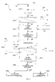
- FIG. 1 is a flow diagram illustrating various aspects of a process for producing copper powder in accordance with one exemplary embodiment of the present invention
- FIG. 2 is a flow diagram illustrating various aspects of a process for producing copper powder in accordance with another exemplary embodiment of the present invention
- FIG. 3 is a flow diagram illustrating various aspects of an electrowinning process in accordance with an exemplary embodiment of the present invention.
- FIGS. 4 through 9 illustrate results from experimentation with various cathode configurations and process parameters in accordance with various aspects of exemplary embodiments of the present invention.
- processes and systems configured according to various embodiments of the present invention enable the efficient and cost-effective utilization of the alternative anode reaction in electrowinning of copper powder at a cell voltage of less than about 1.5 V. Furthermore, the use of such processes and/or systems reduces generation of acid mist.
- copper powder process 100 comprises an electrowinning stage 1010 in which copper powder is electrowon from a copper-containing solution 101 using the ferrous/ferric anode reaction to produce a copper powder slurry stream 102 .
- a copper-containing solution 101 is introduced into an electrowinning cell, and copper is electrowon from the solution to form copper powder.
- a copper powder slurry stream 102 which comprises the copper powder product and electrolyte, is collected and removed from the electrowinning cell, while a lean electrolyte stream 108 exits the electrowinning cell from a side or top portion of the apparatus, preferably from an area generally opposite the entry point of the copper-containing solution to the apparatus.
- the lean electrolyte exiting the electrowinning apparatus may be subjected to filtration to remove suspended copper particles before being recycled to the electrowinning apparatus, utilized in other processing areas, or disposed of.
- the rich electrolyte entering the electrowinning apparatus may be subjected to filtration prior to electrowinning to remove any undesirable solid and/or liquid impurities (including organic liquid impurities).
- the degree of filtration desired generally will be determined by the purity needs of the final copper powder product (in the case of filtration prior to electrowinning), the needs of other processing operations, and/or the amount of solid and/or liquid impurities present in the stream(s).
- ferrous iron for example, in the form of ferrous sulfate (FeSO 4 )
- FeSO 4 ferrous sulfate
- the ferrous/ferric anode reaction may replace the decomposition of water anode reaction (i.e., “conventional” electrowinning chemistry).
- any anode configuration now known or hereafter devised suitable to achieve the processing parameters and objectives described herein may be used in accordance with various embodiments of the present invention.
- various embodiments of the present invention may utilize conventional “plate”-type (i.e., non-flow-through) anodes, other flow-through or non-flow-through anodes of various geometries (e.g., cylindrical anodes), flow-through anodes, or a combination of types within one or more electrowinning cells.
- Any anode, however, that enables electrowinning of copper powder from a copper-containing solution using the ferrous/ferric anode reaction may be employed in connection with the present invention.
- At least one flow-through anode is utilized in connection with the electrowinning cell.
- the term “flow-through anode” refers to any anode configured to enable electrolyte to pass through it. While fluid flow from the electrolyte entry point and/or any other electrolyte flow mechanisms incorporated into the electrowinning cell provide electrolyte movement, a flow-through anode allows the electrolyte in the electrowinning cell to flow through the anode during the electrowinning process.
- any now known or hereafter devised flow-through anode may be utilized in accordance with various exemplary embodiments of the present invention.
- Possible configurations include, but are not limited to, metal, metal wool, metal fabric, other suitable conductive nonmetallic materials (e.g., carbon materials), an expanded porous metal structure, metal mesh, expanded metal mesh, corrugated metal mesh, multiple metal strips, multiple metal wires or rods, woven wire cloth, perforated metal sheets, and the like, or combinations thereof.
- suitable anode configurations are not limited to planar configurations, but may include any suitable multiplanar geometric configuration.
- Anodes employed in conventional electrowinning operations typically comprise lead or a lead alloy, such as, for example, Pb—Sn—Ca.
- a lead alloy such as, for example, Pb—Sn—Ca.
- One significant disadvantage of using such anodes is that, during the electrowinning operation, small amounts of lead are released from the surface of the anode and ultimately cause the generation of undesirable sediments, “sludges,” particulates suspended in the electrolyte, other corrosion products, or other physical degradation products in the electrowinning cell and contamination of the copper product.
- copper produced in operations employing a lead-containing anode typically comprises lead contaminant at a level of from about 0.5 ppm to about 15 ppm.
- the anode is substantially lead-free.
- the anode is formed of one of the so-called “valve” metals, including titanium (Ti), tantalum (Ta), zirconium (Zr), or niobium (Nb).
- the anode may also be formed of other metals, such as nickel (Ni), stainless steel (e.g., Type 316, Type 316L, Type 317, Type 310, etc.), or a metal alloy (e.g., a nickel-chrome alloy), intermetallic mixture, or a ceramic or cermet containing one or more valve metals.
- titanium may be alloyed with nickel, cobalt (Co), iron (Fe), manganese (Mn), or copper (Cu) to form a suitable anode.
- the anode comprises titanium, because, among other things, titanium is rugged and corrosion-resistant. Titanium anodes, for example, when used in accordance with various embodiments of the present invention, potentially have useful lives of up to fifteen years or more.
- the anode may also optionally comprise any electrochemically active coating.
- exemplary coatings include those provided from platinum, ruthenium, iridium, or other Group VIII metals, Group VIII metal oxides, or compounds comprising Group VIII metals, and oxides and compounds of titanium, molybdenum, tantalum, and/or mixtures and combinations thereof.
- Ruthenium oxide and iridium oxide are two preferred compounds for use as an electrochemically active coating on titanium anodes.
- the anode comprises a titanium mesh (or other metal, metal alloy, intermetallic mixture, or ceramic or cermet as set forth above) upon which a coating comprising carbon, graphite, a mixture of carbon and graphite, a precious metal oxide, or a spinel-type coating is applied.
- the anode comprises a titanium mesh with a coating comprised of a mixture of carbon black powder and graphite powder.
- the anode comprises a carbon composite or a metal-graphite sintered material wherein the exemplary metal described is titanium.
- the anode may be formed of a carbon composite material, graphite rods, graphite-carbon coated metallic mesh and the like.
- a metal in the metallic mesh or metal-graphite sintered exemplary embodiment is described herein and shown by example using titanium; however, any metal may be used without detracting from the scope of the present invention. Exemplary embodiments of such anodes are set forth in various of the Examples herein.
- a wire mesh may be welded to the conductor rods, wherein the wire mesh and conductor rods may comprise materials as described above for anodes.
- the wire mesh comprises of a woven wire screen with 80 by 80 strands per square inch, however various mesh configurations may be used, such as, for example, 30 by 30 strands per square inch. Moreover, various regular and irregular geometric mesh configurations may be used.
- a flow-through anode may comprise a plurality of vertically-suspended stainless steel rods, or stainless steel rods fitted with graphite tubes or rings.
- the hanger bar to which the anode body is attached comprises copper or a suitably conductive copper alloy, aluminum, or other suitable conductive material.
- any cathode configuration now known or hereafter devised suitable to achieve the processing parameters and objectives described herein may be used in accordance with various embodiments of the present invention.
- various embodiments of the present invention may utilize conventional “plate”-type (i.e., non-flow-through) cathodes, flow-through cathodes, or a combination of types within one or more electrowinning cells.
- Any cathode, however, that enables electrowinning of copper powder from a copper-containing solution may be employed in connection with the present invention.
- At least one flow-through cathode is utilized in connection with the electrowinning cell.
- the term “cathode” refers to a complete positive electrode assembly (typically connected to a single bar).
- the term “cathode” is used to refer to the group of thin rods, and not to a single rod.
- a flow-through cathode is incorporated into the electrowinning apparatus.
- the term “flow-through cathode” refers to any cathode configured to enable electrolyte to pass through it.
- Various flow-through cathode configurations may be suitable, including: (1) multiple parallel metal wires, thin rods, including hexagonal rods or other geometries, (2) multiple parallel metal strips either aligned with electrolyte flow or inclined at an angle to flow direction, (3) metal mesh, (4) expanded porous metal structure, (5) metal wool or fabric, and/or (6) conductive polymers.
- the cathode may be formed of copper, copper alloy, stainless steel, titanium, aluminum, or any other metal or combination of metals and/or other materials.
- the surface finish of the cathode e.g., whether polished or unpolished) may affect the harvestability of the copper powder. Accordingly, polishing or other surface finishes, surface coatings, surface oxidation layer(s), or any other suitable barrier layer may advantageously be employed to enhance harvestability.
- the cathode may be configured in any manner now known or hereafter devised by the skilled artisan.
- the total surface area of the portion of the cathode that is immersed in the electrolyte during operation of the electrowinning cell is referred to herein, and generally in the literature, as the “active” surface area of the cathode. This is the portion of the cathode onto which copper powder is formed during electrowinning.
- an electrowinning apparatus comprises multiple electrowinning cells configured in series or otherwise electrically connected, each comprising a series of electrodes-alternating anodes and cathodes.
- each electrowinning cell or portion of an electrowinning cell comprises between about 4 and about 80 anodes and between about 4 and about 80 cathodes.
- each electrowinning cell or portion of an electrowinning cell comprises from about 15 to about 40 anodes and about 16 to about 41 cathodes.
- any number of anodes and/or cathodes may be utilized.
- Each electrowinning cell or portions of each electrowinning cell may preferably be configured with a base portion having a collecting configuration, such as, for example, a conical-shaped or trench-shaped base portion, which collects the copper powder product harvested from the cathodes for removal from the electrowinning cell.
- a collecting configuration such as, for example, a conical-shaped or trench-shaped base portion, which collects the copper powder product harvested from the cathodes for removal from the electrowinning cell.
- anode/cathode spacing in conventional electrowinning cells is typically about 2 inches or greater from anode to cathode
- electrowinning cells configured in accordance with various aspects of the present invention preferably exhibit anode/cathode spacing of from about 0.5 inch to about 4 inches, and preferably less than about 2 inches. More preferably, an electrowinning cell configured in accordance with an exemplary embodiment of the present invention exhibits anode/cathode spacing of about or less than about 1.5 inches.
- “anode/cathode spacing” is measured from the centerline of an anode hanger bar to the centerline of the adjacent cathode hanger bar.
- anodes and cathodes in the electrowinning cell may be used effectively in connection with various embodiments of the invention, preferably a flow-through anode is used and electrolyte circulation is provided using an electrolyte flow manifold capable of maintaining satisfactory flow and circulation of electrolyte within the electrowinning cell.
- electrolyte pumping, circulation, or agitation system capable of maintaining satisfactory flow and circulation of electrolyte between the electrodes in an electrowinning cell such that the process specifications described herein are practical may be used in accordance with various embodiments of the invention.
- the electrolyte flow rate is maintained at a level of from about 0.05 gallons per minute per square foot of active cathode to about 30 gallons per minute per square foot of active cathode.
- the electrolyte flow rate is maintained at a level of from about 0.1 gallons per minute per square foot of active cathode to about 0.75 gallons per minute per square foot of active cathode.
- electrolyte flow rate useful in accordance with the present invention will depend upon the specific configuration of the process apparatus employed, and thus flow rates in excess of about 30 gallons per minute per square foot of active cathode or less than about 0.05 gallons per minute per square foot of active cathode may be optimal in accordance with various embodiments of the present invention
- electrolyte movement within the cell may be augmented by agitation, such as through the use of mechanical agitation and/or gas/solution injection devices, to enhance mass transfer.
- overall cell voltage of from about 0.5 V to about 1.5 V is achieved, preferably from about 0.6 V to about 1.1 V, and more preferably from about 0.7 V to about 0.9 V.
- overall cell voltages that are generally less than those achievable through conventional electrowinning reaction chemistry may be utilized.
- the mechanism for optimizing cell voltage within the electrowinning cell will vary in accordance with various exemplary aspects and embodiments of the present invention.
- the overall cell voltage achievable generally is dependent upon a number of interrelated factors, including electrode spacing, the configuration and materials of construction of the electrodes, acid concentration and copper concentration in the electrolyte, current density, electrolyte temperature, and, to a smaller extent, the nature and amount of any additives to the electrowinning process (such as, for example, flocculants, surfactants, and the like).
- the present inventors have recognized that independent control of anode and cathode current densities, together with managing voltage overpotentials, can be utilized to enable effective control of overall cell voltage and current efficiency.
- the configuration of the electrowinning cell hardware including, but not limited to, the ratio of cathode surface area to anode surface area, can be modified in accordance with the present invention to optimize cell operating conditions, current efficiency, and overall cell efficiency.
- the operating current density of the electrowinning cell affects the morphology of the copper powder product and directly affects the production rate of copper powder within the cell. In general, higher current density decreases the bulk density and particle size of the copper powder and increases surface area of the copper powder, while lower current density increases the bulk density of copper product (sometimes resulting in cathode copper if too low, which generally is undesirable in a copper powder electrowinning operation).
- the production rate of copper powder by an electrowinning cell is approximately proportional to the current applied to that cell—a cell operating at, say, 100 A/ft 2 of active cathode produces approximately five times as much copper powder as a cell operating at 20 A/ft 2 of active cathode, all other operating conditions, including active cathode area, remaining constant.
- the current-carrying capacity of the cell furniture is, however, one limiting factor.
- the electrolyte flow rate through the cell may need to be adjusted so as not to deplete the available copper in the electrolyte for electrowinning.
- a cell operating at a high current density may have a higher power demand than a cell operating at a low current density, and as such, economics also plays a role in the choice of operating parameters and optimization of a particular process.
- a current density of from about 10 to about 700 amps per square foot of active cathode is maintained, preferably from about 50 A/ft 2 to about 150 A/ft 2 of active cathode. It should be recognized, however, that the maximum operable current density achievable in accordance with various embodiments of the present invention will depend upon the specific configuration of the process apparatus, the electrolyte flow rate, and other process parameters, and thus an operating current density in excess of 700 A/ft 2 of active cathode may be achievable in accordance with the present invention.
- the temperature of the electrolyte in the electrowinning cell is maintained at from about 40° F. to about 150° F. In accordance with one preferred embodiment, the electrolyte is maintained at a temperature of from about 90° F. to about 140° F. Higher temperatures may, however, be advantageously employed. For example, in direct electrowinning operations, temperatures higher than 140° F. may be utilized. Alternatively, in certain applications, lower temperatures may advantageously be employed. For example, when direct electrowinning of dilute copper-containing solutions is desired, temperatures below 85° F. may be utilized.
- the operating temperature of the electrolyte in the electrowinning cell may be controlled through any one or more of a variety of means well known in the art, including, for example, heat exchange, an immersion heating element, an in-line heating device (e.g., a heat exchanger), or the like, preferably coupled with one or more feedback temperature control means for efficient process control.
- the acid concentration in the electrolyte for electrowinning may be maintained at a level of from about 5 to about 200 grams of acid per liter of electrolyte.
- the acid concentration in the electrolyte is advantageously maintained at a level of from about 100 to about 180 grams of acid per liter of electrolyte, depending upon the upstream process.
- the acid concentration in the electrolyte is advantageously maintained at a level of from about 150 to about 160 grams of acid per liter of electrolyte.
- the copper concentration in the electrolyte for electrowinning is advantageously maintained at a level of from about 5 to about 40 grams of copper per liter of electrolyte.
- the copper concentration is maintained at a level of from about 10 g/L to about 30 g/L.
- the copper concentration in the electrolyte is advantageously maintained at a level of from about 15 to about 25 grams per liter of electrolyte.
- various aspects of the present invention may be beneficially applied to processes employing copper concentrations above and/or below these levels, with lower copper concentration levels of from about 0.5 to about 5 g/L and upper copper concentration levels of from about 40 g/L to about 50 g/L being applied in some cases.
- the total iron concentration in the electrolyte is maintained at a level of from about 10 to about 60 grams of iron per liter of electrolyte.
- the total iron concentration in the electrolyte is maintained at a level of from about 30 g/L to about 50 g/L, and more preferably, from about 40 g/L to about 50 g/L.
- the total iron concentration in the electrolyte may vary in accordance with various embodiments of the invention, as total iron concentration is a function of iron solubility in the electrolyte.
- Iron solubility in the electrolyte varies with other process parameters, such as, for example, acid concentration, copper concentration, and temperature. As explained hereinabove, decreasing iron concentration in the electrolyte is generally economically desirable, because doing so decreases iron make-up requirements and decreases the electrolyte sulfate saturation temperature, and thus decreases the cost of operating the electrowinning cell.
- the total iron concentration in the electrolyte is maintained at a suitable level, preferably as much ferrous iron as can be retained, typically on the order of from about 0.001 to about 10 grams of iron per liter of electrolyte.
- the concentration of ferrous iron in the electrolyte is naturally depleted, while the concentration of ferric iron in the electrolyte is naturally increased.
- the concentration of ferrous iron in the electrolyte is controlled by addition of ferrous sulfate to the electrolyte.
- the concentration of ferrous iron in the electrolyte is controlled by solution extraction (SX) of iron from copper leaching solutions.
- Ferrous/ferric ions also can be leached from the ore, concentrate, or any other iron source (e.g., pyrite, marcasite, pyrrhotite, scrap iron) to generate additional iron, preferably in the form of ferrous ions that do not require regeneration prior to addition to the electrolyte.
- any other iron source e.g., pyrite, marcasite, pyrrhotite, scrap iron
- the ferric iron generated at the anode preferably is reduced back to ferrous iron to maintain a satisfactory ferrous concentration in the electrolyte. Additionally, the ferric iron concentration preferably is controlled to achieve satisfactory current efficiency in the electrowinning cell.
- the ferric iron concentration in the electrolyte is maintained at a level of from about 0.001 to about 10 grams of iron per liter of electrolyte.
- the ferric iron concentration in the electrolyte is maintained at a level of from about 1 g/L to about 6 g/L, and more preferably, from about 2 g/L to about 4 g/L.
- the concentration of ferric iron in the electrolyte within the electrowinning cell is controlled by removing at least a portion of the electrolyte from the electrowinning cell, for example, as illustrated in FIG. 3 as electrolyte regeneration stream 35 of process 300 .
- sulfur dioxide 37 may be used to reduce the ferric iron in electrolyte regeneration stream 35 .
- reduction of Fe 3+ to Fe 2+ in electrolyte regeneration stream 35 in ferrous regeneration stage 303 may be accomplished using any suitable reducing reagent or method, sulfur dioxide is particularly attractive as a reducing agent for Fe 3+ because it is generally available from other copper processing operations, and because sulfuric acid is generated as a byproduct.
- the sulfur dioxide Upon reacting with ferric iron in a copper-containing electrolyte, the sulfur dioxide is oxidized, forming sulfuric acid.
- the reaction of sulfur dioxide with ferric iron produces two moles of sulfuric acid for each mole of copper produced in the electrowinning cell, which is one mole more of acid than is typically required to maintain the acid balance within the overall copper extraction process, when solution extraction (SX) is used in conjunction with electrowinning.
- the excess sulfuric acid may be extracted from the acid-rich electrolyte (illustrated in FIG. 3 as stream 38 ) generated in the ferrous regeneration stage for use in other operations, such as, for example, leaching operations.
- the acid-rich electrolyte stream 38 from ferrous regeneration stage 301 may be returned to electrowinning stage 1010 via electrolyte recycle streams 32 and 36 , may be introduced to acid removal stage 302 for further processing, or may be split (as shown in FIG. 3 ) such that a portion of acid-rich electrolyte stream 38 returns to electrowinning stage 1010 and a portion continues to acid removal stage 302 .
- acid removal stage 302 excess sulfuric acid is extracted from the acid-rich electrolyte and leaves the process via acid stream 39 , to be neutralized or, preferably, used in other operations, such as, for example a heap leach operation.
- the acid-reduced electrolyte stream 34 may then be returned to electrowinning stage 1010 via electrolyte recycle stream 36 , as shown in FIG. 3 .
- the ferric-rich electrolyte is contacted with sulfur dioxide in the presence of a catalyst, such as, for example, activated carbon manufactured from bituminous coal, or other types of carbon with a suitable active surface and suitable structure.
- a catalyst such as, for example, activated carbon manufactured from bituminous coal, or other types of carbon with a suitable active surface and suitable structure.
- the reaction of sulfur dioxide and ferric iron is preferably monitored such that the concentration of ferric iron and ferrous iron in the acid-rich electrolyte stream produced in the ferrous regeneration stage can be controlled.
- two or more oxidation-reduction potential (ORP) sensors are used—at least one ORP sensor in the ferric-rich electrolyte line upstream from the injection point of sulfur dioxide, and at least one ORP sensor downstream from the catalytic reaction point in the ferric-lean electrolyte.
- the ORP measurements provide an indication of the ferric/ferrous ratio in the solution; however, the exact measurements depend on overall solution conditions that may be unique to any particular application. Those skilled in the art will recognize that any number of methods and/or apparatus may be utilized to monitor and control the ferric/ferrous ratio in the solution.
- the ferric-rich electrolyte will contain from about 0.001 to about 10 grams per liter ferric iron, and the ferric-lean electrolyte will contain up to about 6 grams per liter ferric iron.
- any number of mechanisms may be utilized to harvest the copper powder product from the cathode in accordance with various aspects of the present invention.
- the optimal harvesting mechanism for a particular embodiment of the present invention will depend largely on a number of interrelated factors, primarily current density, copper concentration in the electrolyte, electrolyte flow rate, and electrolyte temperature. Other contributing factors include the level of mixing within the electrowinning apparatus, the frequency and duration of the harvesting method, and the presence and amount of any process additives (such as, for example, flocculant, surfactants, and the like).
- In situ harvesting configurations may be desirable to minimize the need to remove and handle cathodes to facilitate the removal of copper powder from the electrowinning cell.
- in situ harvesting configurations may advantageously permit the use of fixed electrode cell designs. As such, any number of mechanisms and configurations may be utilized.
- Examples of possible harvesting mechanisms include vibration (e.g., one or more vibration and/or impact devices affixed to one or more cathodes to displace copper powder from the cathode surface at predetermined time intervals), a pulse flow system (e.g., electrolyte flow rate increased dramatically for a short time to displace copper powder from the cathode surface), use of a pulsed power supply to the cell, use of ultrasonic waves, and use of other mechanical displacement means to remove copper powder from the cathode surface, such as intermittent or continuous air bubbles.
- vibration e.g., one or more vibration and/or impact devices affixed to one or more cathodes to displace copper powder from the cathode surface at predetermined time intervals
- a pulse flow system e.g., electrolyte flow rate increased dramatically for a short time to displace copper powder from the cathode surface
- use of a pulsed power supply to the cell use of ultrasonic waves
- fine copper powder that is carried through the cell with the electrolyte is removed via a suitable filtration, sedimentation, or other fines removal/recovery system.
- a process for producing copper powder includes the steps of: (i) electrowinning copper powder from a copper-containing solution to produce a slurry stream containing copper powder particles and electrolyte; (ii) optionally, separating at least a portion of the electrolyte from the copper powder particles in the slurry stream; (iii) conditioning the slurry stream; (iv) optionally, separating the bulk of the liquid from the copper powder particles; and (v) optionally, drying the copper powder particles originally present in the slurry stream to produce a final, stable copper powder product.
- copper powder slurry stream 102 from electrowinning stage 1010 optionally is subjected to solid/liquid separation (step 1020 ) to reduce the amount of electrolyte in stream 102 .
- Optional solid/liquid separation stage 1020 may comprise any apparatus now known or hereafter developed for separating at least a portion of the electrolyte (stream 104 ) from the copper powder in copper powder slurry stream 102 , such as, for example, a clarifier, a spiral classifier, other screw-type devices, a countercurrent decantation (CCD) circuit, a thickener, a filter, a conveyor-type device, a gravity separation device, or other suitable apparatus.
- the solid/liquid separation apparatus chosen will enable separation of electrolyte from the copper powder while preventing exposure of the copper powder to air, which can cause rapid surface oxidation of the copper powder particles.
- At least a portion of electrolyte stream 104 leaving solid/liquid separation stage 1020 may be recycled to the electrowinning cell (stream 112 ) and/or may be combined with lean electrolyte stream 108 (stream 111 ).
- copper powder slurry stream 102 from electrowinning stage 1010 has a solids content of from about 5 percent by weight to about 30 percent by weight.
- the solids content of copper powder slurry stream 102 from electrowinning stage 1010 is largely dependent upon the copper powder harvesting method chosen in electrowinning stage 1010 .
- solid/liquid separation stage 1020 when used, is configured to produce a concentrated copper powder slurry stream 103 that has a solids content of at least about 20 percent by weight, and preferably greater than about 30 percent by weight, for example, in the range of about 60 percent to about 80 percent by weight or more depending upon the bulk density and morphology of the copper powder.
- High solids content may be advantageous, particularly if coarse or granular copper powder is harvested. It is generally desirable to separate as much electrolyte as possible from the copper powder prior to subjecting the copper powder slurry stream to further processing, as doing so potentially reduces the cost of downstream processing (e.g., by reducing process stream volume and thus capital and operating expenses) and potentially increases the quality of the final copper powder product (e.g., by reducing surface oxidation of the copper powder particles by the electrolyte and by reducing levels of entrained impurities).
- conditioning stage 1030 is configured to (i) adjust of the pH of concentrated copper powder slurry stream 103 , (ii) stabilize the surface of the copper powder particles to prevent surface oxidation, and/or (iii) further reduce the amount of excess liquid in the copper powder slurry stream to form a moist copper powder product. Adjustment of the pH of concentrated copper powder slurry stream 103 and stabilization of the surface of the copper powder particles in copper powder slurry stream 103 is facilitated by the addition of one or more conditioning agents 105 to conditioning stage 1030 .
- conditioning stage 1030 comprises any apparatus now known or hereafter developed capable of achieving the above objectives, and, in particular, capable of treating substantially all surfaces of the copper particles reasonably equally with conditioning agents 105 .
- conditioning stage 1030 comprises use of a centrifuge. Exemplary processing parameters for conditioning stage 1030 are discussed hereinbelow in connection with another embodiment of the present invention.
- a dewatering stage 1040 be employed to enable a bulk of the liquid in copper powder stream 106 to be separated from the bulk of the copper powder as economically as possible.
- a centrifuge, a filter, or other suitable solid/liquid separation apparatus may be used.
- this separation may be accomplished during and/or in connection with conditioning the copper powder slurry in conditioning stage 1030 , such as in connection with conditioning stage 1030 when use of a centrifugal conditioning step is carried out.
- additional dewatering may be desired to yield a copper powder product that is useable for future processing without additional conditioning and/or processing (e.g., drying).
- drying stage 1050 comprises any apparatus now known or hereafter developed capable of drying the copper powder sufficiently for packaging as a final product and/or for transfer to downstream process and for downstream processing steps for formation of alternative copper products.
- drying stage 1050 may comprise a flash dryer, a cyclone, a dry sintering apparatus, a conveyor belt dryer, and/or other suitable apparatus.
- the excess heat from the melting process may be used beneficially to dry the copper powder product.
- a process for producing copper powder includes the steps of (i) electrowinning copper powder from a copper-containing solution to produce a slurry stream containing copper powder particles and electrolyte; (ii) optionally, separating at least a portion of the electrolyte from the copper powder particles in the slurry stream; (iii) optionally, separating one or more coarse copper powder particle size distributions in the slurry stream from one or more finer copper powder particle size distributions in the slurry stream in one or more size classification stages; (iv) optionally, conditioning the slurry stream; (v) separating the bulk of the liquid from the copper powder particles; (vi) optionally, drying the copper powder particles in the slurry stream to produce a dry copper powder stream; (vii) optionally, separating one or more coarse copper powder particle size distributions in the dry copper powder stream from one or more finer copper powder particle size distributions in the dry copper powder stream in one or more size classification stages; and (viii) either collecting the copper
- a copper-containing solution 201 is provided to an electrowinning stage 2010 .
- Electrowinning stage 2010 is configured to produce a copper powder slurry stream 203 , which comprises copper powder and an electrolyte, and a lean electrolyte stream 202 .
- Lean electrolyte stream 202 may be recycled to upstream processing operations (such as, for example, an upstream leaching operation used to produce copper-containing solution 201 ), used in other processing operations, or impounded or disposed of.
- upstream processing operations such as, for example, an upstream leaching operation used to produce copper-containing solution 201
- the excess heat from the melting process may be used beneficially to dry the said copper product.
- copper powder slurry stream 203 then optionally undergoes solid/liquid separation in solid/liquid separation (or “dewatering”) stage 2020 , which may, as described above in connection with FIG. 1 , comprise any apparatus now known or hereafter developed for separating at least a portion of the bulk electrolyte (stream 204 ) from the copper powder in copper powder slurry stream 203 , such as, for example, a clarifier, a spiral classifier, a screw-type device, a countercurrent decantation (CCD) circuit, a thickener, a filter, a gravitational separator device, a conveyor-type device, or other suitable apparatus.
- a clarifier a clarifier
- a spiral classifier a screw-type device
- a countercurrent decantation (CCD) circuit a thickener
- filter a filter
- gravitational separator device a gravitational separator device
- conveyor-type device or other suitable apparatus.
- Such an advantageous bulk liquid removal step may yield a copper powder product that is useable for future processing without additional conditioning and/or processing.
- semi-continuous copper powder harvesting within the electrowinning cell is advantageously matched with batch downstream processing (i.e., dewatering and conditioning) such that copper powder product is more continuously recovered.
- batch downstream processing i.e., dewatering and conditioning
- multiple solid/liquid separation devices may be employed in connection with a conditioning stage, and as such, downstream solid/liquid separation may be eliminated.
- the resulting concentrated copper powder slurry from solid/liquid separation stage 2020 may be collected in a copper powder slurry tank 2030 .
- Copper powder slurry tank 2030 is configured to hold the concentrated copper slurry and to maintain homogeneity of the slurry through mixing, agitation, or other means.
- process water 215 and/or a pH-adjusting agent 216 such as, for example, ammonium hydroxide
- slurry tank 2030 is configured such that the copper powder slurry is not exposed to air during storage and/or treatment, as such exposure may, as described above, detrimentally affect the surface integrity of the copper powder particles.
- slurry stream 206 may, optionally, undergo a size classification stage 2040 .
- the objective of size classification stage 2040 is to separate coarser copper powder particles from finer copper powder particles in the slurry stream, in accordance with specifications for the desired final copper powder product. For example, if the final copper powder product is to be used for extruding copper shapes or other products, such as by direct rotary extrusion, a slurry stream comprising finer copper powder particles is preferred, whereas if the final copper powder product is to be melted for rod or other product formation, relatively coarse copper powder particles may be preferable.
- the term “coarse” describes copper powder particles larger than about 200 microns (in the range of about plus 100 mesh).
- fine is used herein to describe copper powder particles smaller than about 50 microns (in the range of about minus 325 mesh). Particles between those ranges are referred to as “intermediate” particles.
- size classification When size classification is desired, it may be carried out at any suitable stage in the copper powder production process, the suitability of any stage being dependent upon a variety of factors, including the size of the copper powder particles leaving the electrowinning stage, the configuration and materials of construction of the size classification apparatus, and other engineering and economic process considerations.
- size classification when utilized, size classification may be conducted on the slurry stream leaving the electrowinning cell, the optional slurry tank (prior to conditioning), and/or on the copper powder product stream. Such processing may allow for stabilization of fine particles and different treatment of coarser particles. In the event size classification is conducted, the different particle size distributions, or, if desired, various mixtures thereof, may be processed further, as will now be discussed.
- slurry stream 207 (or slurry stream 206 , if size classification is not utilized) is subjected to an optional conditioning operation 2050 to condition the copper powder and/or the solution in preparation for dewatering and optional drying.
- conditioning operation 2050 when used, may be performed in conjunction with a dewatering operation 2060 .
- optional conditioning operation 2050 may include washing, pH adjustment, removal of impurities, stabilization, and/or other conditioning operations.
- the copper slurry may be contacted with a washing agent 208 and/or a stabilizing agent 209 .
- Washing agent 208 can comprise any liquid material, water, ammonium hydroxide, and/or mixtures thereof.
- washing agent 208 may include additional materials, such as, for example, surfactants, soaps, and the like.
- washing agent 208 may be heated prior to washing, which may enhance impurity removal.
- Stabilizing agent 209 may be any agent suitable for preventing surface oxidation of the copper powder particles (which oxidation may diminish the value and/or quality of the copper powder product and/or may negatively impact downstream operations or applications).
- stabilizing agent 209 comprises an organic surfactant in combination with a stabilizer.
- the organic surfactant may be used to lower the surface tension of the stabilizer and thus enable the stabilizer to penetrate into all pores of the copper powder particles.
- the stabilizer on the other hand, preferably is the “active” agent that coats the particles and prevents oxidation, thus providing a suitable shelf life to the copper powder product and enabling transfer of the copper powder in an otherwise oxidizing atmosphere (i.e., air).
- Some suitable stabilizers include, for example, 1,2,3-Benzotriazole (BTA), animal glue, fish glue, soaps, and the like.
- a stabilization agent may be unnecessary, such as when the copper powder product is intended to be processed immediately after production (by melting and casting, for example).
- other methods of preventing surface oxidation of the copper powder particles during processing may reduce or eliminate the need for a stabilization agent, such as, for example, use of a charged fluidized bed or use of nitrogen blanketing during one or more stages of copper powder handling. If it is desirable to store the copper powder product for an extended period of time, however, then a stabilizing agent may be desired.
- a dewatering stage 2060 be employed to enable a bulk of the liquid in copper powder stream 211 to be separated from the bulk of the copper powder as economically as possible.
- a centrifuge, a filter, or other suitable solid/liquid separation apparatus may be used.
- this separation may be accomplished during or in connection with conditioning the copper powder slurry, such as in connection with optional conditioning operation 2050 .
- Such an advantageous dewatering step may yield a copper powder product that is useable for future processing without additional conditioning and/or processing (e.g., drying).
- a dewatering stage 2060 is utilized to draw as much liquid from copper powder slurry 211 as possible, producing a moist copper powder stream 212 .
- Moist copper powder stream 212 may then be subjected to an optional drying stage 2070 to produce a final copper powder product stream 213 .
- optional drying stage 2070 comprises any apparatus now known or hereafter developed capable of drying the copper powder sufficiently for packaging as a final product and/or for shipping to downstream process and for downstream processing steps for formation of alternative copper products.
- drying stage 2070 may comprise a flash dryer, a fluid bed dryer, a rotary dryer, a cyclone, a dry sintering apparatus, a conveyor belt dryer, and/or other suitable apparatus for direct or indirect drying.
- optional drying stage 2070 comprises a flash dryer that enables rapid drying of the copper powder particles without disturbing the integrity of the stabilizer coating on the copper powder particles.
- moist copper powder stream 212 is contacted with sufficient hot air for a period of time sufficient to reduce the moisture content of the copper powder particles.
- the final moisture content of the copper powder product stream 213 may vary, depending upon the nature of any downstream processing of the copper powder (through, for example, size classification, packaging, direct forming of copper shapes and rods, casting, briquetting, and the like). In this regard, in certain applications, significant moisture content may be retained without deleteriously impacting subsequent processing.
- copper powder product stream 213 may optionally undergo size classification in size classification stage 2080 to achieve a desired particle size distribution in the final copper powder product 214 .
- the final copper powder product 214 may then be sent to a packaging operation 2090 —for example, a bagging operation—or may be subjected to further processing 2095 to change the character of the final copper product.
- the electrolyte therefore flowed through the electrodes, not from side to side.
- a recirculation tank with an immersion heater and pump were attached to the electrowinning cell to provide electrolyte to the cell.
- Process variables studied included current density, electrolyte flow rate, copper concentration, and iron concentration.
- the conditions that most favored copper powder formation on the cathode included low copper concentration, high current density, small diameter cathode rods, the use of titanium cathodes, and low electrolyte flow rate. Conditions were found where copper powder that is easily harvestable can be produced.
- Table 1 contains the experimental design. Fixed variables for this design included electrolyte chemistry (44 to 48 g/L copper, 22 to 26 g/L iron, 150 to 160 g/L sulfuric acid), and electrolyte temperature of 120° F. Dependent variables (measured variables) were cell voltage and the harvestability of the copper powder produced (i.e., whether the electrowon copper was easily removed as powder, or whether it formed pseudo-cathode, a cathode-powder intermediate that tends to stick to the cathode). As the experimental results were obtained, new tests were designed to explore specific areas of interest. As a result of the electrolyte chemistry and the anodes utilized in this testing, the anode reaction in the cell was the oxidation of ferrous to ferric iron.
- the harvesting method utilized in each test was to open 1-inch side flow ports on the side of the electrowinning cell one by one for a short period of time. This imposed an electrolyte flow of approximately 20 gpm on individual sections of the cathode rods, causing the electrowon copper powder to fall off the cathode rods. If residual powder remained on the cathode rods at the end of the harvest cycle, the entire cathode was lifted and the powder was removed by hand. Harvest cycles were typically 1 to 2 hours.
- FIG. 4 illustrates the effect of current density on cell voltage and copper powder harvestability using 3 ⁇ 4-inch stainless steel or 3 ⁇ 4-inch titanium cathode rods, an electrolyte flow rate of 10 or 50 gpm, and an electrolyte containing 44 to 48 g/L copper, 22 to 26 g/L iron, 150 to 160 g/L sulfuric acid, and maintained at a temperature of 120° F. Additional current density points were added to the experiment design because of the pseudo-cathode plate that was evident at an operating current density of 300 A/ft 2 .
- Titanium cathode rods were tested at 500, 600, and 700 A/ft 2 for comparison. At 10 gpm electrolyte flow, the titanium rod cathode exhibited an all-powder deposit and the electrowon copper powder was more easily harvested than when the 3 ⁇ 4-inch stainless steel rod cathode was tested under the same conditions.
- the test results with the 3 ⁇ 4-inch titanium cathode rods at 50 gpm are set forth in FIG. 5 .
- pseudo-cathode plate was evident at 500 and 600 A/ft 2
- the electrowon copper was an all-powder deposit.
- a current density of 700 A/ft 2 was required at the higher flow rate to produce an all-powder deposit.
- FIG. 6 sets forth the results obtained using smaller diameter cathode rods.
- 1 ⁇ 8-inch diameter titanium rods were not immediately available, and so 1 ⁇ 4-inch rods were substituted.
- a 1 ⁇ 4-inch hexagonal titanium rod cathode was also tested. The tests were conducted at 10 gpm electrolyte flow only.
- As the results in FIG. 6 demonstrate, when using a cathode with smaller diameter rods, a lower current density can be operated while still maintaining an all-powder copper deposit. Pseudo-cathode plate was observed on the 1 ⁇ 8-inch stainless steel cathode rods at an operating current density of 100 A/ft 2 , but not in the other tests displayed in FIG. 6 .
- FIG. 9 is a summary showing electrowinning power consumption as a function of current density at 10 gpm electrolyte flow rate and 120° F. In order to operate at less than 0.5 W-hr/lb copper, a current density of 100 A/ft 2 is indicated.
Abstract
Description
Cu2++SO4 2−+2e −→Cu0+SO4 2− (E 0=+0.345 V)
H2O→½O2+2H++2e − (E 0=−1.230 V)
Cu2++SO4 2−+H2O→Cu0+2H++SO4 2−+½O2 (E 0=−0.885 V)
Cu2++SO4 2−+2e −→Cu0+SO4 2− (E 0=+0.345 V)
2Fe2+→2Fe3++2e − (E 0=−0.770 V)
Cu2++SO4 2−+2Fe2+→Cu0+2Fe3++SO4 2− (E 0=−0.425 V)
2Fe3++SO2+2H2O→2Fe2++4H++SO4 2−
| TABLE 1 |
| Exploratory experiment design for copper powder production. |
| Current | Electrolyte Flow | Cathode Material | Cathode Rod |
| Density, A/ft2 | Rate, Gpm | of Construction | Diameter, |
| 300 | 10 | 316 Stainless | ⅛ |
| |
|||
| 600 | 50 | Titanium | ¾ |
Claims (19)
Priority Applications (1)
| Application Number | Priority Date | Filing Date | Title |
|---|---|---|---|
| US12/332,641 US7736475B2 (en) | 2003-07-28 | 2008-12-11 | System and method for producing copper powder by electrowinning using the ferrous/ferric anode reaction |
Applications Claiming Priority (4)
| Application Number | Priority Date | Filing Date | Title |
|---|---|---|---|
| US10/629,497 US7378011B2 (en) | 2003-07-28 | 2003-07-28 | Method and apparatus for electrowinning copper using the ferrous/ferric anode reaction |
| US59088204P | 2004-07-22 | 2004-07-22 | |
| US11/160,910 US7494580B2 (en) | 2003-07-28 | 2005-07-14 | System and method for producing copper powder by electrowinning using the ferrous/ferric anode reaction |
| US12/332,641 US7736475B2 (en) | 2003-07-28 | 2008-12-11 | System and method for producing copper powder by electrowinning using the ferrous/ferric anode reaction |
Related Parent Applications (1)
| Application Number | Title | Priority Date | Filing Date |
|---|---|---|---|
| US11/160,910 Continuation US7494580B2 (en) | 2003-07-28 | 2005-07-14 | System and method for producing copper powder by electrowinning using the ferrous/ferric anode reaction |
Publications (2)
| Publication Number | Publication Date |
|---|---|
| US20090145749A1 US20090145749A1 (en) | 2009-06-11 |
| US7736475B2 true US7736475B2 (en) | 2010-06-15 |
Family
ID=34103638
Family Applications (4)
| Application Number | Title | Priority Date | Filing Date |
|---|---|---|---|
| US10/629,497 Expired - Fee Related US7378011B2 (en) | 2003-07-28 | 2003-07-28 | Method and apparatus for electrowinning copper using the ferrous/ferric anode reaction |
| US12/126,552 Expired - Fee Related US7704354B2 (en) | 2003-07-28 | 2008-05-23 | Method and apparatus for electrowinning copper using the ferrous/ferric anode reaction |
| US12/332,641 Expired - Fee Related US7736475B2 (en) | 2003-07-28 | 2008-12-11 | System and method for producing copper powder by electrowinning using the ferrous/ferric anode reaction |
| US12/752,933 Expired - Fee Related US8187450B2 (en) | 2003-07-28 | 2010-04-01 | Method and apparatus for electrowinning copper using ferrous/ferric anode reaction |
Family Applications Before (2)
| Application Number | Title | Priority Date | Filing Date |
|---|---|---|---|
| US10/629,497 Expired - Fee Related US7378011B2 (en) | 2003-07-28 | 2003-07-28 | Method and apparatus for electrowinning copper using the ferrous/ferric anode reaction |
| US12/126,552 Expired - Fee Related US7704354B2 (en) | 2003-07-28 | 2008-05-23 | Method and apparatus for electrowinning copper using the ferrous/ferric anode reaction |
Family Applications After (1)
| Application Number | Title | Priority Date | Filing Date |
|---|---|---|---|
| US12/752,933 Expired - Fee Related US8187450B2 (en) | 2003-07-28 | 2010-04-01 | Method and apparatus for electrowinning copper using ferrous/ferric anode reaction |
Country Status (15)
| Country | Link |
|---|---|
| US (4) | US7378011B2 (en) |
| EP (1) | EP1660700B1 (en) |
| JP (2) | JP4451445B2 (en) |
| AP (1) | AP1865A (en) |
| AT (1) | ATE417144T1 (en) |
| AU (1) | AU2004261975B2 (en) |
| BR (1) | BRPI0413023B1 (en) |
| CA (1) | CA2533650C (en) |
| DE (1) | DE602004018333D1 (en) |
| EA (1) | EA011201B1 (en) |
| MX (1) | MXPA06001149A (en) |
| PE (1) | PE20050637A1 (en) |
| PL (1) | PL379760A1 (en) |
| WO (1) | WO2005012597A2 (en) |
| ZA (1) | ZA200600948B (en) |
Cited By (10)
| Publication number | Priority date | Publication date | Assignee | Title |
|---|---|---|---|---|
| US20100224484A1 (en) * | 2004-07-22 | 2010-09-09 | Freeport-Mcmoran Corporation | System and method for producing copper powder by electrowinning in a flow-through electrowinning cell |
| US20100276281A1 (en) * | 2009-04-29 | 2010-11-04 | Phelps Dodge Corporation | Anode structure for copper electrowinning |
| WO2013154997A1 (en) | 2012-04-09 | 2013-10-17 | Ohio University | Method of producing graphene |
| US8936770B2 (en) | 2010-01-22 | 2015-01-20 | Molycorp Minerals, Llc | Hydrometallurgical process and method for recovering metals |
| US9011669B2 (en) | 2012-09-17 | 2015-04-21 | Blue Planet Strategies, L.L.C. | Apparatus and method for electrochemical modification of liquids |
| WO2015108596A2 (en) | 2013-10-25 | 2015-07-23 | Ohio University | Electrochemical cell containing a graphene coated electrode |
| US9150974B2 (en) | 2011-02-16 | 2015-10-06 | Freeport Minerals Corporation | Anode assembly, system including the assembly, and method of using same |
| US9605353B2 (en) | 2011-05-27 | 2017-03-28 | Blue Planet Strategies, L.L.C. | Apparatus and method for advanced electrochemical modification of liquids |
| US10544482B2 (en) | 2015-07-06 | 2020-01-28 | Sherritt International Corporation | Recovery of copper from arsenic-containing process feed |
| US11118244B2 (en) | 2017-04-14 | 2021-09-14 | Sherritt International Corporation | Low acidity, low solids pressure oxidative leaching of sulphidic feeds |
Families Citing this family (45)
| Publication number | Priority date | Publication date | Assignee | Title |
|---|---|---|---|---|
| US7494580B2 (en) * | 2003-07-28 | 2009-02-24 | Phelps Dodge Corporation | System and method for producing copper powder by electrowinning using the ferrous/ferric anode reaction |
| US7378011B2 (en) | 2003-07-28 | 2008-05-27 | Phelps Dodge Corporation | Method and apparatus for electrowinning copper using the ferrous/ferric anode reaction |
| US7470356B2 (en) * | 2004-03-17 | 2008-12-30 | Kennecott Utah Copper Corporation | Wireless monitoring of two or more electrolytic cells using one monitoring device |
| AU2005224674B2 (en) * | 2004-03-17 | 2010-02-25 | Kennecott Utah Copper Llc | Monitoring electrolytic cell currents |
| US7368049B2 (en) * | 2004-06-22 | 2008-05-06 | Phelps Dodge Corporation | Method and apparatus for electrowinning copper using the ferrous/ferric anode reaction and a flow-through anode |
| US20060021880A1 (en) * | 2004-06-22 | 2006-02-02 | Sandoval Scot P | Method and apparatus for electrowinning copper using the ferrous/ferric anode reaction and a flow-through anode |
| US7393438B2 (en) * | 2004-07-22 | 2008-07-01 | Phelps Dodge Corporation | Apparatus for producing metal powder by electrowinning |
| US7452455B2 (en) * | 2004-07-22 | 2008-11-18 | Phelps Dodge Corporation | System and method for producing metal powder by electrowinning |
| AP2236A (en) | 2005-03-29 | 2011-05-23 | Cytec Tech Corp | Modification of copper/iron selectivity in copper solvent extraction systems. |
| US20070284262A1 (en) * | 2006-06-09 | 2007-12-13 | Eugene Yanjun You | Method of Detecting Shorts and Bad Contacts in an Electrolytic Cell |
| FI120438B (en) | 2006-08-11 | 2009-10-30 | Outotec Oyj | A method for forming a metal powder |
| US8517053B2 (en) * | 2007-04-26 | 2013-08-27 | Westinghouse Electric Company Llc | Cartridge type vortex suppression device |
| CA2712274A1 (en) * | 2008-01-17 | 2009-07-23 | Freeport-Mcmoran Corporation | Method and apparatus for electrowinning copper with ferrous/ferric anode reaction electrowinning |
| CN102317244A (en) | 2009-01-29 | 2012-01-11 | 普林斯顿大学 | Carbonic acid gas is converted into organic product |
| MD4032C2 (en) * | 2009-05-22 | 2010-11-30 | Государственный Университет Молд0 | Process for the regeneration of an electrolyte for the deposition of iron platings |
| FI124812B (en) * | 2010-01-29 | 2015-01-30 | Outotec Oyj | Method and apparatus for the manufacture of metal powder |
| US8845877B2 (en) | 2010-03-19 | 2014-09-30 | Liquid Light, Inc. | Heterocycle catalyzed electrochemical process |
| US8721866B2 (en) | 2010-03-19 | 2014-05-13 | Liquid Light, Inc. | Electrochemical production of synthesis gas from carbon dioxide |
| US8500987B2 (en) | 2010-03-19 | 2013-08-06 | Liquid Light, Inc. | Purification of carbon dioxide from a mixture of gases |
| US8845878B2 (en) | 2010-07-29 | 2014-09-30 | Liquid Light, Inc. | Reducing carbon dioxide to products |
| US8961774B2 (en) | 2010-11-30 | 2015-02-24 | Liquid Light, Inc. | Electrochemical production of butanol from carbon dioxide and water |
| US8568581B2 (en) | 2010-11-30 | 2013-10-29 | Liquid Light, Inc. | Heterocycle catalyzed carbonylation and hydroformylation with carbon dioxide |
| US9090976B2 (en) | 2010-12-30 | 2015-07-28 | The Trustees Of Princeton University | Advanced aromatic amine heterocyclic catalysts for carbon dioxide reduction |
| CN104024478A (en) | 2011-07-06 | 2014-09-03 | 液体光有限公司 | Carbon Dioxide Capture And Conversion To Organic Products |
| CN103649374A (en) | 2011-07-06 | 2014-03-19 | 液体光有限公司 | Reduction of carbon dioxide to carboxylic acids, glycols, and carboxylates |
| PL396693A1 (en) * | 2011-10-19 | 2013-04-29 | Nano-Tech Spólka Z Ograniczona Odpowiedzialnoscia | New method for electrolytes' copper removal in the copper industry |
| KR20140138153A (en) * | 2012-03-06 | 2014-12-03 | 리퀴드 라이트 인코포레이티드 | Reducing carbon dioxide to products |
| FI125808B (en) * | 2012-03-09 | 2016-02-29 | Outotec Oyj | Anode and method for using an electrolytic cell |
| CN103374732A (en) * | 2012-04-11 | 2013-10-30 | 王惟华 | Anode scrap-free tandem electrolyzing device with anode material storing box |
| WO2013152617A1 (en) * | 2012-04-11 | 2013-10-17 | Wang Weihua | Electrolysis apparatus with anode material storage tank |
| US9267212B2 (en) | 2012-07-26 | 2016-02-23 | Liquid Light, Inc. | Method and system for production of oxalic acid and oxalic acid reduction products |
| US8641885B2 (en) | 2012-07-26 | 2014-02-04 | Liquid Light, Inc. | Multiphase electrochemical reduction of CO2 |
| US20130105304A1 (en) | 2012-07-26 | 2013-05-02 | Liquid Light, Inc. | System and High Surface Area Electrodes for the Electrochemical Reduction of Carbon Dioxide |
| US9175407B2 (en) | 2012-07-26 | 2015-11-03 | Liquid Light, Inc. | Integrated process for producing carboxylic acids from carbon dioxide |
| US10329676B2 (en) | 2012-07-26 | 2019-06-25 | Avantium Knowledge Centre B.V. | Method and system for electrochemical reduction of carbon dioxide employing a gas diffusion electrode |
| US9303324B2 (en) | 2012-07-26 | 2016-04-05 | Liquid Light, Inc. | Electrochemical co-production of chemicals with sulfur-based reactant feeds to anode |
| WO2014043651A2 (en) | 2012-09-14 | 2014-03-20 | Liquid Light, Inc. | High pressure electrochemical cell and process for the electrochemical reduction of carbon dioxide |
| JP5962525B2 (en) * | 2013-01-28 | 2016-08-03 | 住友金属鉱山株式会社 | Electrolyte solution supply apparatus and method |
| CL2014001133A1 (en) * | 2014-04-30 | 2014-11-03 | Propipe Maqunarias Limitada | Insertable (dei) electrode device that replaces the traditional anode in electro-metal processes, which does not generate acid mist or other gases, comprising a perimeter frame arranged on both sides of the device, ion exchange membranes, strategic electrode that is a conductor or semiconductor, inlet and outlet duct, vertical electric busbars; device application procedure. |
| CN104032328B (en) * | 2014-06-04 | 2016-08-31 | 杭州三耐环保科技有限公司 | A kind of environment-friendly and energy-efficient diaphragm electrolysis apparatus |
| US9938632B2 (en) | 2015-02-10 | 2018-04-10 | Faraday Technology, Inc. | Apparatus and method for recovery of material generated during electrochemical material removal in acidic electrolytes |
| CN109666952B (en) * | 2017-10-16 | 2020-12-04 | 中国科学院过程工程研究所 | Method for producing metallic silver by electrodeposition |
| KR102409510B1 (en) * | 2021-03-31 | 2022-06-14 | 일렉트로-액티브 테크놀로지즈 인크. | Bioelectrical Process Control and Methods of Use Thereof |
| US11663792B2 (en) | 2021-09-08 | 2023-05-30 | Snap Inc. | Body fitted accessory with physics simulation |
| US11790614B2 (en) | 2021-10-11 | 2023-10-17 | Snap Inc. | Inferring intent from pose and speech input |
Citations (100)
| Publication number | Priority date | Publication date | Assignee | Title |
|---|---|---|---|---|
| US2792342A (en) | 1956-01-26 | 1957-05-14 | Phelps Dodge Corp | Electrowinning of copper |
| US3262870A (en) | 1961-08-31 | 1966-07-26 | Powdered Metals Corp | Process for the extraction of copper |
| US3616277A (en) | 1968-07-26 | 1971-10-26 | Kennecott Copper Corp | Method for the electrodeposition of copper powder |
| US3632498A (en) | 1967-02-10 | 1972-01-04 | Chemnor Ag | Electrode and coating therefor |
| US3703358A (en) | 1969-08-21 | 1972-11-21 | Gen Electric | Method of generating hydrogen with magnesium reactant |
| US3711385A (en) | 1970-09-25 | 1973-01-16 | Chemnor Corp | Electrode having platinum metal oxide coating thereon,and method of use thereof |
| US3853724A (en) | 1973-07-24 | 1974-12-10 | Goold R | Process for electrowinning of copper values from solid particles in a sulfuric acid electrolyte |
| US3876516A (en) | 1973-02-14 | 1975-04-08 | Continental Oil Co | Copper electrowinning process |
| US3887396A (en) | 1973-11-15 | 1975-06-03 | Us Energy | Modular electrochemical cell |
| US3915834A (en) | 1974-04-01 | 1975-10-28 | Kennecott Copper Corp | Electrowinning cell having an anode with no more than one-half the active surface area of the cathode |
| US3956086A (en) | 1974-05-17 | 1976-05-11 | Cjb Development Limited | Electrolytic cells |
| US3972795A (en) | 1974-09-11 | 1976-08-03 | Hazen Research, Inc. | Axial flow electrolytic cell |
| US3979275A (en) | 1974-02-25 | 1976-09-07 | Kennecott Copper Corporation | Apparatus for series electrowinning and electrorefining of metal |
| US3981353A (en) | 1975-01-16 | 1976-09-21 | Knight Bill J | Anode casting machine |
| SU589290A1 (en) | 1976-05-24 | 1978-01-25 | Уральский Ордена Трудового Красного Знамени Политехнический Институт Имени С.М.Кирова | Plate cathode for electrolytic preparation of metallic powders |
| US4071431A (en) | 1975-06-18 | 1978-01-31 | Socomaten | Installation for the treatment of metals pickling solutions |
| US4098668A (en) | 1974-08-21 | 1978-07-04 | Continental Copper & Steel Industries, Inc. | Electrolyte metal extraction |
| US4129494A (en) | 1977-05-04 | 1978-12-12 | Norman Telfer E | Electrolytic cell for electrowinning of metals |
| SU715900A1 (en) | 1978-01-05 | 1980-02-15 | Уральский Научно-Исследовательский И Проектный Институт Медной Промышленности | Copper powder drying method |
| US4201653A (en) | 1977-10-11 | 1980-05-06 | Inco Limited | Electrowinning cell with bagged anode |
| US4219401A (en) | 1978-08-07 | 1980-08-26 | The D-H Titanium Company | Metal electrowinning feed cathode |
| US4226685A (en) | 1978-10-23 | 1980-10-07 | Kennecott Copper Corporation | Electrolytic treatment of plating wastes |
| US4272339A (en) | 1980-03-10 | 1981-06-09 | Knight Bill J | Process for electrowinning of metals |
| US4278521A (en) | 1978-05-30 | 1981-07-14 | Dechema | Electrochemical cell |
| US4288305A (en) | 1979-10-10 | 1981-09-08 | Inco Limited | Process for electrowinning nickel or cobalt |
| US4292160A (en) | 1979-08-20 | 1981-09-29 | Kennecott Corporation | Apparatus for electrochemical removal of heavy metals such as chromium from dilute wastewater streams using flow-through porous electrodes |
| US4318789A (en) * | 1979-08-20 | 1982-03-09 | Kennecott Corporation | Electrochemical removal of heavy metals such as chromium from dilute wastewater streams using flow through porous electrodes |
| US4373654A (en) | 1980-11-28 | 1983-02-15 | Rsr Corporation | Method of manufacturing electrowinning anode |
| US4399020A (en) | 1981-07-24 | 1983-08-16 | Diamond Shamrock Corporation | Device for waste water treatment |
| CA1162514A (en) | 1980-01-21 | 1984-02-21 | Sankar Das Gupta | Apparatus for waste treatment equipment |
| US4436601A (en) | 1981-07-24 | 1984-03-13 | Diamond Shamrock Corporation | Metal removal process |
| US4445990A (en) | 1981-11-12 | 1984-05-01 | General Electric Company | Electrolytic reactor for cleaning wastewater |
| SU1090760A1 (en) | 1981-09-01 | 1984-05-07 | Уральский Ордена Трудового Красного Знамени Научно-Исследовательский И Проектный Институт Медной Промышленности "Унипромедь" | Method for producing copper powder |
| EP0129845A1 (en) | 1983-06-24 | 1985-01-02 | American Cyanamid Company | Electrodes, electro-chemical cells containing said electrodes, and process for forming and utilizing such electrodes |
| US4515672A (en) | 1981-11-09 | 1985-05-07 | Eltech Systems Corporation | Reticulate electrode and cell for recovery of metal ions |
| SU1183566A1 (en) | 1983-06-13 | 1985-10-07 | Уральский ордена Трудового Красного Знамени политехнический институт им.С.М.Кирова | Electrolyte for producing metal powders |
| US4556469A (en) | 1981-11-12 | 1985-12-03 | General Electric Environmental Services, Inc. | Electrolytic reactor for cleaning wastewater |
| US4560453A (en) | 1985-03-28 | 1985-12-24 | Exxon Research And Engineering Co. | Efficient, safe method for decoppering copper refinery electrolyte |
| US4565748A (en) | 1985-01-31 | 1986-01-21 | Dahl Ernest A | Magnetically operated electrolyte circulation system |
| SU1243907A1 (en) | 1983-03-03 | 1986-07-15 | Уральский ордена Трудового Красного Знамени политехнический институт им.С.М.Кирова | Method of producing copper powder by electrolysis |
| EP0206941A1 (en) | 1985-06-21 | 1986-12-30 | Enriqué Hermana Tezanos | Cathode for metal electrowinning |
| US4680100A (en) | 1982-03-16 | 1987-07-14 | American Cyanamid Company | Electrochemical cells and electrodes therefor |
| SU1346697A1 (en) | 1985-12-30 | 1987-10-23 | Уральский политехнический институт им.С.М.Кирова | Method of obtaining copper powder by electrolysis |
| US4715934A (en) | 1985-11-18 | 1987-12-29 | Lth Associates | Process and apparatus for separating metals from solutions |
| US4762603A (en) | 1983-06-24 | 1988-08-09 | American Cyanamid Company | Process for forming electrodes |
| SU1418349A1 (en) | 1986-04-23 | 1988-08-23 | Уральский политехнический институт им.С.М.Кирова | Electrolyte for producing copper powder by electrolysis |
| US4789450A (en) | 1986-12-16 | 1988-12-06 | Bateman Engineering (International) Limited | Electrolytic cell |
| US4834850A (en) | 1987-07-27 | 1989-05-30 | Eltech Systems Corporation | Efficient electrolytic precious metal recovery system |
| US4863580A (en) | 1988-08-10 | 1989-09-05 | Epner R L | Waste metal extraction apparatus |
| SU1537711A1 (en) | 1987-12-15 | 1990-01-23 | Уральский политехнический институт им.С.М.Кирова | Method of producing copper powder by electrolysis |
| JPH02229778A (en) | 1989-03-01 | 1990-09-12 | Dowa Mining Co Ltd | Method for metallizing nonoxide ceramics |
| US4960500A (en) | 1988-08-10 | 1990-10-02 | Epner R L | Waste metal extraction apparatus |
| US5006216A (en) | 1989-12-07 | 1991-04-09 | Eltech Systems Corporation | Metal removal apparatus |
| SU1708939A1 (en) | 1989-06-14 | 1992-01-30 | Уральский политехнический институт им.С.М.Кирова | Method for production of copper powder |
| US5128012A (en) | 1990-05-07 | 1992-07-07 | Elkem Aluminium Ans | Arrangement for closing the top of a Soderberg anode in an electrolytic cell or production of aluminum |
| US5133843A (en) | 1990-09-10 | 1992-07-28 | The Dow Chemical Company | Method for the recovery of metals from the membrane of electrochemical cells |
| SU1813806A1 (en) | 1990-03-06 | 1993-05-07 | N Proizv Ob Edinenie Armtsvetm | Process for preparing copper powder |
| US5277777A (en) | 1991-09-28 | 1994-01-11 | B.U.S. Engitec Servizi Ambientali S.R.L. | Insoluble anode for electrolyses in aqueous solutions |
| US5292412A (en) | 1990-04-12 | 1994-03-08 | Eltech Systems Corporation | Removal of mercury from waste streams |
| US5324409A (en) | 1990-03-17 | 1994-06-28 | Heraeus Electrochemie Gmbh | Electrode arrangement for electrolytic cells |
| US5368702A (en) | 1990-11-28 | 1994-11-29 | Moltech Invent S.A. | Electrode assemblies and mutimonopolar cells for aluminium electrowinning |
| US5454917A (en) | 1993-09-03 | 1995-10-03 | Cognis, Inc. | Apparatus and process for recovering metal from an aqueous solution |
| US5458746A (en) | 1993-04-19 | 1995-10-17 | Magma Copper Company | Process for making copper metal powder, copper oxides and copper foil |
| US5492608A (en) | 1994-03-14 | 1996-02-20 | The United States Of America As Represented By The Secretary Of The Interior | Electrolyte circulation manifold for copper electrowinning cells which use the ferrous/ferric anode reaction |
| US5516412A (en) | 1995-05-16 | 1996-05-14 | International Business Machines Corporation | Vertical paddle plating cell |
| US5622615A (en) | 1996-01-04 | 1997-04-22 | The University Of British Columbia | Process for electrowinning of copper matte |
| US5690806A (en) | 1993-09-10 | 1997-11-25 | Ea Technology Ltd. | Cell and method for the recovery of metals from dilute solutions |
| US5705048A (en) | 1996-03-27 | 1998-01-06 | Oxley Research, Inc. | Apparatus and a process for regenerating a CUCl2 etchant |
| US5725752A (en) | 1993-10-22 | 1998-03-10 | Ea Technology Ltd. | Electrokinetic decontamination of land |
| US5770037A (en) | 1996-11-21 | 1998-06-23 | Konica Corporation | Water processing method |
| US5783050A (en) | 1995-05-04 | 1998-07-21 | Eltech Systems Corporation | Electrode for electrochemical cell |
| US5837122A (en) | 1997-04-21 | 1998-11-17 | The Scientific Ecology Group, Inc. | Electrowinning electrode, cell and process |
| DE19731616A1 (en) | 1997-07-23 | 1999-01-28 | Henry Prof Dr Bergmann | Metal ion removal from electrolyte |
| US5877388A (en) | 1994-02-01 | 1999-03-02 | Kabushiki Kaisha Toshiba | Apparatus and method for electrochemical decontamination of radioactive metallic waste |
| US5882502A (en) | 1992-04-01 | 1999-03-16 | Rmg Services Pty Ltd. | Electrochemical system and method |
| US5908540A (en) | 1997-08-07 | 1999-06-01 | International Business Machines Corporation | Copper anode assembly for stabilizing organic additives in electroplating of copper |
| US6017428A (en) | 1997-07-16 | 2000-01-25 | Summit Valley Equipment And Engineering, Inc. | Electrowinning cell |
| US6086691A (en) | 1997-08-04 | 2000-07-11 | Lehockey; Edward M. | Metallurgical process for manufacturing electrowinning lead alloy electrodes |
| US6086733A (en) | 1998-10-27 | 2000-07-11 | Eastman Kodak Company | Electrochemical cell for metal recovery |
| US6113758A (en) | 1998-07-30 | 2000-09-05 | Moltech Invent S.A. | Porous non-carbon metal-based anodes for aluminium production cells |
| US6139705A (en) | 1998-05-06 | 2000-10-31 | Eltech Systems Corporation | Lead electrode |
| US6149797A (en) | 1998-10-27 | 2000-11-21 | Eastman Kodak Company | Method of metal recovery using electrochemical cell |
| US6214179B1 (en) | 1997-12-28 | 2001-04-10 | Kemix (Proprietary) Limited | Electrowinning cell |
| US6231730B1 (en) | 1999-12-07 | 2001-05-15 | Epvirotech Pumpsystems, Inc. | Cathode frame |
| RU2169443C1 (en) | 1999-12-15 | 2001-06-20 | Камский политехнический институт | Process of generation of electrolytic electric discharge and gear for its implementation |
| US6319389B1 (en) | 1999-11-24 | 2001-11-20 | Hydromet Systems, L.L.C. | Recovery of copper values from copper ores |
| FR2810681A1 (en) | 2000-06-27 | 2001-12-28 | Claude Andre Bedjai | Recovery of precious metal, notably gold, from a variety of wastes involves electrolytic dissolution of gold and electrolytic deposition of gold from solution on an electrode |
| US6340423B1 (en) | 1999-04-12 | 2002-01-22 | Bhp Minerals International, Inc. | Hydrometallurgical processing of lead materials using fluotitanate |
| US6352622B1 (en) | 1998-05-06 | 2002-03-05 | Eltech Systems Corporation | Lead electrode |
| US6398939B1 (en) | 2001-03-09 | 2002-06-04 | Phelps Dodge Corporation | Method and apparatus for controlling flow in an electrodeposition process |
| US6402930B1 (en) | 1999-05-27 | 2002-06-11 | De Nora Elettrodi S.P.A. | Process for the electrolysis of technical-grade hydrochloric acid contaminated with organic substances using oxygen-consuming cathodes |
| US6451183B1 (en) | 1999-08-11 | 2002-09-17 | Electrometals Technologies Limited | Method and apparatus for electrowinning powder metal from solution |
| US20040168909A1 (en) | 2003-02-28 | 2004-09-02 | Larson Arden L. | Three-dimensional flow-through electrode and electrochemical cell |
| US20050023151A1 (en) | 2003-07-28 | 2005-02-03 | Sandoval Scot Philip | Method and apparatus for electrowinning copper using the ferrous/ferric anode reaction |
| US20050269209A1 (en) | 2003-07-28 | 2005-12-08 | Phelps Dodge Corporation | System and method for producing copper powder by electrowinning using the ferrous/ferric anode reaction |
| US20060021880A1 (en) * | 2004-06-22 | 2006-02-02 | Sandoval Scot P | Method and apparatus for electrowinning copper using the ferrous/ferric anode reaction and a flow-through anode |
| US20060226024A1 (en) | 2004-06-22 | 2006-10-12 | Phelps Dodge Corporation | Method and apparatus for electrowinning copper using the ferrous/ferric anode reaction and a flow-through anode |
| US7378010B2 (en) | 2004-07-22 | 2008-05-27 | Phelps Dodge Corporation | System and method for producing copper powder by electrowinning in a flow-through electrowinning cell |
| US7393438B2 (en) * | 2004-07-22 | 2008-07-01 | Phelps Dodge Corporation | Apparatus for producing metal powder by electrowinning |
| US7452455B2 (en) * | 2004-07-22 | 2008-11-18 | Phelps Dodge Corporation | System and method for producing metal powder by electrowinning |
Family Cites Families (4)
| Publication number | Priority date | Publication date | Assignee | Title |
|---|---|---|---|---|
| GB1433800A (en) * | 1973-12-27 | 1976-04-28 | Imi Refinery Holdings Ltd | Method of and anodes for use in electrowinning metals |
| JPH02229788A (en) * | 1989-02-28 | 1990-09-12 | Sumitomo Metal Ind Ltd | Vapor phase growth device |
| JP2938285B2 (en) * | 1992-09-16 | 1999-08-23 | 同和鉱業株式会社 | Chelate resin solution for copper electrolyte |
| US6391170B1 (en) * | 2000-12-01 | 2002-05-21 | Envirotech Pumpsystems, Inc. | Anode box for electrometallurgical processes |
-
2003
- 2003-07-28 US US10/629,497 patent/US7378011B2/en not_active Expired - Fee Related
-
2004
- 2004-07-26 EP EP04779290A patent/EP1660700B1/en not_active Not-in-force
- 2004-07-26 PE PE2004000717A patent/PE20050637A1/en not_active Application Discontinuation
- 2004-07-26 AP AP2006003531A patent/AP1865A/en active
- 2004-07-26 CA CA2533650A patent/CA2533650C/en not_active Expired - Fee Related
- 2004-07-26 JP JP2006521998A patent/JP4451445B2/en not_active Expired - Fee Related
- 2004-07-26 EA EA200600285A patent/EA011201B1/en not_active IP Right Cessation
- 2004-07-26 AT AT04779290T patent/ATE417144T1/en not_active IP Right Cessation
- 2004-07-26 PL PL379760A patent/PL379760A1/en not_active Application Discontinuation
- 2004-07-26 MX MXPA06001149A patent/MXPA06001149A/en active IP Right Grant
- 2004-07-26 DE DE602004018333T patent/DE602004018333D1/en active Active
- 2004-07-26 BR BRPI0413023-5B1A patent/BRPI0413023B1/en not_active IP Right Cessation
- 2004-07-26 AU AU2004261975A patent/AU2004261975B2/en not_active Ceased
- 2004-07-26 WO PCT/US2004/024162 patent/WO2005012597A2/en active Search and Examination
-
2006
- 2006-02-01 ZA ZA200600948A patent/ZA200600948B/en unknown
-
2008
- 2008-05-23 US US12/126,552 patent/US7704354B2/en not_active Expired - Fee Related
- 2008-12-11 US US12/332,641 patent/US7736475B2/en not_active Expired - Fee Related
-
2009
- 2009-02-16 JP JP2009033312A patent/JP2009161860A/en active Pending
-
2010
- 2010-04-01 US US12/752,933 patent/US8187450B2/en not_active Expired - Fee Related
Patent Citations (108)
| Publication number | Priority date | Publication date | Assignee | Title |
|---|---|---|---|---|
| US2792342A (en) | 1956-01-26 | 1957-05-14 | Phelps Dodge Corp | Electrowinning of copper |
| US3262870A (en) | 1961-08-31 | 1966-07-26 | Powdered Metals Corp | Process for the extraction of copper |
| US3632498A (en) | 1967-02-10 | 1972-01-04 | Chemnor Ag | Electrode and coating therefor |
| US3616277A (en) | 1968-07-26 | 1971-10-26 | Kennecott Copper Corp | Method for the electrodeposition of copper powder |
| US3703358A (en) | 1969-08-21 | 1972-11-21 | Gen Electric | Method of generating hydrogen with magnesium reactant |
| US3711385A (en) | 1970-09-25 | 1973-01-16 | Chemnor Corp | Electrode having platinum metal oxide coating thereon,and method of use thereof |
| US3876516A (en) | 1973-02-14 | 1975-04-08 | Continental Oil Co | Copper electrowinning process |
| US3853724A (en) | 1973-07-24 | 1974-12-10 | Goold R | Process for electrowinning of copper values from solid particles in a sulfuric acid electrolyte |
| US3887396A (en) | 1973-11-15 | 1975-06-03 | Us Energy | Modular electrochemical cell |
| US3979275A (en) | 1974-02-25 | 1976-09-07 | Kennecott Copper Corporation | Apparatus for series electrowinning and electrorefining of metal |
| US3915834A (en) | 1974-04-01 | 1975-10-28 | Kennecott Copper Corp | Electrowinning cell having an anode with no more than one-half the active surface area of the cathode |
| US3956086A (en) | 1974-05-17 | 1976-05-11 | Cjb Development Limited | Electrolytic cells |
| US4098668A (en) | 1974-08-21 | 1978-07-04 | Continental Copper & Steel Industries, Inc. | Electrolyte metal extraction |
| US3972795A (en) | 1974-09-11 | 1976-08-03 | Hazen Research, Inc. | Axial flow electrolytic cell |
| US3981353A (en) | 1975-01-16 | 1976-09-21 | Knight Bill J | Anode casting machine |
| US4071431A (en) | 1975-06-18 | 1978-01-31 | Socomaten | Installation for the treatment of metals pickling solutions |
| SU589290A1 (en) | 1976-05-24 | 1978-01-25 | Уральский Ордена Трудового Красного Знамени Политехнический Институт Имени С.М.Кирова | Plate cathode for electrolytic preparation of metallic powders |
| US4129494A (en) | 1977-05-04 | 1978-12-12 | Norman Telfer E | Electrolytic cell for electrowinning of metals |
| US4201653A (en) | 1977-10-11 | 1980-05-06 | Inco Limited | Electrowinning cell with bagged anode |
| SU715900A1 (en) | 1978-01-05 | 1980-02-15 | Уральский Научно-Исследовательский И Проектный Институт Медной Промышленности | Copper powder drying method |
| US4278521A (en) | 1978-05-30 | 1981-07-14 | Dechema | Electrochemical cell |
| US4219401A (en) | 1978-08-07 | 1980-08-26 | The D-H Titanium Company | Metal electrowinning feed cathode |
| US4226685A (en) | 1978-10-23 | 1980-10-07 | Kennecott Copper Corporation | Electrolytic treatment of plating wastes |
| US4318789A (en) * | 1979-08-20 | 1982-03-09 | Kennecott Corporation | Electrochemical removal of heavy metals such as chromium from dilute wastewater streams using flow through porous electrodes |
| US4292160A (en) | 1979-08-20 | 1981-09-29 | Kennecott Corporation | Apparatus for electrochemical removal of heavy metals such as chromium from dilute wastewater streams using flow-through porous electrodes |
| US4288305A (en) | 1979-10-10 | 1981-09-08 | Inco Limited | Process for electrowinning nickel or cobalt |
| CA1162514A (en) | 1980-01-21 | 1984-02-21 | Sankar Das Gupta | Apparatus for waste treatment equipment |
| US4272339A (en) | 1980-03-10 | 1981-06-09 | Knight Bill J | Process for electrowinning of metals |
| US4373654A (en) | 1980-11-28 | 1983-02-15 | Rsr Corporation | Method of manufacturing electrowinning anode |
| US4399020A (en) | 1981-07-24 | 1983-08-16 | Diamond Shamrock Corporation | Device for waste water treatment |
| US4436601A (en) | 1981-07-24 | 1984-03-13 | Diamond Shamrock Corporation | Metal removal process |
| SU1090760A1 (en) | 1981-09-01 | 1984-05-07 | Уральский Ордена Трудового Красного Знамени Научно-Исследовательский И Проектный Институт Медной Промышленности "Унипромедь" | Method for producing copper powder |
| US4515672A (en) | 1981-11-09 | 1985-05-07 | Eltech Systems Corporation | Reticulate electrode and cell for recovery of metal ions |
| US4556469A (en) | 1981-11-12 | 1985-12-03 | General Electric Environmental Services, Inc. | Electrolytic reactor for cleaning wastewater |
| US4445990A (en) | 1981-11-12 | 1984-05-01 | General Electric Company | Electrolytic reactor for cleaning wastewater |
| US4680100A (en) | 1982-03-16 | 1987-07-14 | American Cyanamid Company | Electrochemical cells and electrodes therefor |
| SU1243907A1 (en) | 1983-03-03 | 1986-07-15 | Уральский ордена Трудового Красного Знамени политехнический институт им.С.М.Кирова | Method of producing copper powder by electrolysis |
| SU1183566A1 (en) | 1983-06-13 | 1985-10-07 | Уральский ордена Трудового Красного Знамени политехнический институт им.С.М.Кирова | Electrolyte for producing metal powders |
| EP0129845A1 (en) | 1983-06-24 | 1985-01-02 | American Cyanamid Company | Electrodes, electro-chemical cells containing said electrodes, and process for forming and utilizing such electrodes |
| US4762603A (en) | 1983-06-24 | 1988-08-09 | American Cyanamid Company | Process for forming electrodes |
| US4565748A (en) | 1985-01-31 | 1986-01-21 | Dahl Ernest A | Magnetically operated electrolyte circulation system |
| US4560453A (en) | 1985-03-28 | 1985-12-24 | Exxon Research And Engineering Co. | Efficient, safe method for decoppering copper refinery electrolyte |
| EP0206941A1 (en) | 1985-06-21 | 1986-12-30 | Enriqué Hermana Tezanos | Cathode for metal electrowinning |
| US4776941A (en) | 1985-06-21 | 1988-10-11 | Tezanos Enrique H | Cathode for metal electrowinning |
| US4715934A (en) | 1985-11-18 | 1987-12-29 | Lth Associates | Process and apparatus for separating metals from solutions |
| SU1346697A1 (en) | 1985-12-30 | 1987-10-23 | Уральский политехнический институт им.С.М.Кирова | Method of obtaining copper powder by electrolysis |
| SU1418349A1 (en) | 1986-04-23 | 1988-08-23 | Уральский политехнический институт им.С.М.Кирова | Electrolyte for producing copper powder by electrolysis |
| US4789450A (en) | 1986-12-16 | 1988-12-06 | Bateman Engineering (International) Limited | Electrolytic cell |
| US4834850A (en) | 1987-07-27 | 1989-05-30 | Eltech Systems Corporation | Efficient electrolytic precious metal recovery system |
| SU1537711A1 (en) | 1987-12-15 | 1990-01-23 | Уральский политехнический институт им.С.М.Кирова | Method of producing copper powder by electrolysis |
| US4863580A (en) | 1988-08-10 | 1989-09-05 | Epner R L | Waste metal extraction apparatus |
| US4960500A (en) | 1988-08-10 | 1990-10-02 | Epner R L | Waste metal extraction apparatus |
| JPH02229778A (en) | 1989-03-01 | 1990-09-12 | Dowa Mining Co Ltd | Method for metallizing nonoxide ceramics |
| SU1708939A1 (en) | 1989-06-14 | 1992-01-30 | Уральский политехнический институт им.С.М.Кирова | Method for production of copper powder |
| US5006216A (en) | 1989-12-07 | 1991-04-09 | Eltech Systems Corporation | Metal removal apparatus |
| SU1813806A1 (en) | 1990-03-06 | 1993-05-07 | N Proizv Ob Edinenie Armtsvetm | Process for preparing copper powder |
| US5324409A (en) | 1990-03-17 | 1994-06-28 | Heraeus Electrochemie Gmbh | Electrode arrangement for electrolytic cells |
| US5292412A (en) | 1990-04-12 | 1994-03-08 | Eltech Systems Corporation | Removal of mercury from waste streams |
| US5128012A (en) | 1990-05-07 | 1992-07-07 | Elkem Aluminium Ans | Arrangement for closing the top of a Soderberg anode in an electrolytic cell or production of aluminum |
| US5133843A (en) | 1990-09-10 | 1992-07-28 | The Dow Chemical Company | Method for the recovery of metals from the membrane of electrochemical cells |
| US5368702A (en) | 1990-11-28 | 1994-11-29 | Moltech Invent S.A. | Electrode assemblies and mutimonopolar cells for aluminium electrowinning |
| US5277777A (en) | 1991-09-28 | 1994-01-11 | B.U.S. Engitec Servizi Ambientali S.R.L. | Insoluble anode for electrolyses in aqueous solutions |
| US5882502A (en) | 1992-04-01 | 1999-03-16 | Rmg Services Pty Ltd. | Electrochemical system and method |
| US5458746A (en) | 1993-04-19 | 1995-10-17 | Magma Copper Company | Process for making copper metal powder, copper oxides and copper foil |
| US5454917A (en) | 1993-09-03 | 1995-10-03 | Cognis, Inc. | Apparatus and process for recovering metal from an aqueous solution |
| US5690806A (en) | 1993-09-10 | 1997-11-25 | Ea Technology Ltd. | Cell and method for the recovery of metals from dilute solutions |
| US5725752A (en) | 1993-10-22 | 1998-03-10 | Ea Technology Ltd. | Electrokinetic decontamination of land |
| US5877388A (en) | 1994-02-01 | 1999-03-02 | Kabushiki Kaisha Toshiba | Apparatus and method for electrochemical decontamination of radioactive metallic waste |
| US5492608A (en) | 1994-03-14 | 1996-02-20 | The United States Of America As Represented By The Secretary Of The Interior | Electrolyte circulation manifold for copper electrowinning cells which use the ferrous/ferric anode reaction |
| US5783050A (en) | 1995-05-04 | 1998-07-21 | Eltech Systems Corporation | Electrode for electrochemical cell |
| US5972181A (en) | 1995-05-04 | 1999-10-26 | Eltech Systems, Corp. | Electrode and electrochemical cell |
| US5516412A (en) | 1995-05-16 | 1996-05-14 | International Business Machines Corporation | Vertical paddle plating cell |
| US5622615A (en) | 1996-01-04 | 1997-04-22 | The University Of British Columbia | Process for electrowinning of copper matte |
| US5705048A (en) | 1996-03-27 | 1998-01-06 | Oxley Research, Inc. | Apparatus and a process for regenerating a CUCl2 etchant |
| US5770037A (en) | 1996-11-21 | 1998-06-23 | Konica Corporation | Water processing method |
| US5837122A (en) | 1997-04-21 | 1998-11-17 | The Scientific Ecology Group, Inc. | Electrowinning electrode, cell and process |
| US6017428A (en) | 1997-07-16 | 2000-01-25 | Summit Valley Equipment And Engineering, Inc. | Electrowinning cell |
| DE19731616A1 (en) | 1997-07-23 | 1999-01-28 | Henry Prof Dr Bergmann | Metal ion removal from electrolyte |
| US6086691A (en) | 1997-08-04 | 2000-07-11 | Lehockey; Edward M. | Metallurgical process for manufacturing electrowinning lead alloy electrodes |
| US5908540A (en) | 1997-08-07 | 1999-06-01 | International Business Machines Corporation | Copper anode assembly for stabilizing organic additives in electroplating of copper |
| US6214179B1 (en) | 1997-12-28 | 2001-04-10 | Kemix (Proprietary) Limited | Electrowinning cell |
| US6352622B1 (en) | 1998-05-06 | 2002-03-05 | Eltech Systems Corporation | Lead electrode |
| US6139705A (en) | 1998-05-06 | 2000-10-31 | Eltech Systems Corporation | Lead electrode |
| US6113758A (en) | 1998-07-30 | 2000-09-05 | Moltech Invent S.A. | Porous non-carbon metal-based anodes for aluminium production cells |
| US6149797A (en) | 1998-10-27 | 2000-11-21 | Eastman Kodak Company | Method of metal recovery using electrochemical cell |
| US6086733A (en) | 1998-10-27 | 2000-07-11 | Eastman Kodak Company | Electrochemical cell for metal recovery |
| US6340423B1 (en) | 1999-04-12 | 2002-01-22 | Bhp Minerals International, Inc. | Hydrometallurgical processing of lead materials using fluotitanate |
| US6402930B1 (en) | 1999-05-27 | 2002-06-11 | De Nora Elettrodi S.P.A. | Process for the electrolysis of technical-grade hydrochloric acid contaminated with organic substances using oxygen-consuming cathodes |
| US6451183B1 (en) | 1999-08-11 | 2002-09-17 | Electrometals Technologies Limited | Method and apparatus for electrowinning powder metal from solution |
| US6319389B1 (en) | 1999-11-24 | 2001-11-20 | Hydromet Systems, L.L.C. | Recovery of copper values from copper ores |
| US6231730B1 (en) | 1999-12-07 | 2001-05-15 | Epvirotech Pumpsystems, Inc. | Cathode frame |
| RU2169443C1 (en) | 1999-12-15 | 2001-06-20 | Камский политехнический институт | Process of generation of electrolytic electric discharge and gear for its implementation |
| FR2810681A1 (en) | 2000-06-27 | 2001-12-28 | Claude Andre Bedjai | Recovery of precious metal, notably gold, from a variety of wastes involves electrolytic dissolution of gold and electrolytic deposition of gold from solution on an electrode |
| US6398939B1 (en) | 2001-03-09 | 2002-06-04 | Phelps Dodge Corporation | Method and apparatus for controlling flow in an electrodeposition process |
| US20040168909A1 (en) | 2003-02-28 | 2004-09-02 | Larson Arden L. | Three-dimensional flow-through electrode and electrochemical cell |
| US20050269209A1 (en) | 2003-07-28 | 2005-12-08 | Phelps Dodge Corporation | System and method for producing copper powder by electrowinning using the ferrous/ferric anode reaction |
| US20050023151A1 (en) | 2003-07-28 | 2005-02-03 | Sandoval Scot Philip | Method and apparatus for electrowinning copper using the ferrous/ferric anode reaction |
| US7378011B2 (en) | 2003-07-28 | 2008-05-27 | Phelps Dodge Corporation | Method and apparatus for electrowinning copper using the ferrous/ferric anode reaction |
| US7494580B2 (en) * | 2003-07-28 | 2009-02-24 | Phelps Dodge Corporation | System and method for producing copper powder by electrowinning using the ferrous/ferric anode reaction |
| US20060021880A1 (en) * | 2004-06-22 | 2006-02-02 | Sandoval Scot P | Method and apparatus for electrowinning copper using the ferrous/ferric anode reaction and a flow-through anode |
| US20060226024A1 (en) | 2004-06-22 | 2006-10-12 | Phelps Dodge Corporation | Method and apparatus for electrowinning copper using the ferrous/ferric anode reaction and a flow-through anode |
| US20080047839A1 (en) * | 2004-06-22 | 2008-02-28 | Phelps Dodge Corporation | Method and apparatus for electrowinning copper using the ferrous/ferric anode reaction and a flow-through anode |
| US7368049B2 (en) | 2004-06-22 | 2008-05-06 | Phelps Dodge Corporation | Method and apparatus for electrowinning copper using the ferrous/ferric anode reaction and a flow-through anode |
| US20080105556A1 (en) * | 2004-06-22 | 2008-05-08 | Phelps Dodge Corporation | Method and apparatus for electrowinning copper using the ferrous/ferric anode reaction and a flow-through anode |
| US7378010B2 (en) | 2004-07-22 | 2008-05-27 | Phelps Dodge Corporation | System and method for producing copper powder by electrowinning in a flow-through electrowinning cell |
| US7393438B2 (en) * | 2004-07-22 | 2008-07-01 | Phelps Dodge Corporation | Apparatus for producing metal powder by electrowinning |
| US20080217185A1 (en) * | 2004-07-22 | 2008-09-11 | Phelps Dodge Corporation | System and method for producing copper power by electrowinning in a flow-through electrowinning cell |
| US7452455B2 (en) * | 2004-07-22 | 2008-11-18 | Phelps Dodge Corporation | System and method for producing metal powder by electrowinning |
Non-Patent Citations (29)
| Title |
|---|
| Alkire, et al.; "Flow-Through Porous Electrodes", J. Electrochem. Soc.; vol. 122, No. 12, pp. 1594-1601; Dec. 1975. |
| Allen, et al.; "Energy Savings by Means of Fuel Cell Electrodes in Electro-Chemical Industries", Dept. of Energy, Journal Announcement: GRAI8018; NSA0500, Mar. 19, 1979, p. 72. |
| Barbosa, et al.; "On-line coupling of electrochemical preconcentration in tungsten coil electrothermal atomic absorption spectrometry for determination of lead in natural waters", Spectrochimica Acta-Part B Atomic Spectroscopy, v. 54, n 8, 1999, p. 1155-1166. |
| Bechtold, et al.; "Optimization of multi-cathode membrane electrolyzers for the indirect electrochemical reduction of indigo"; Chemical Engineering & Technology, v. 21, n. 11, Nov. 1998; pp. 877-880. |
| Chin, Der-Tau; "Metal recovery from wastewater with an electrochemical method", Chemical Engineering Education, v. 36, No. 2, Spring 2002. |
| Cook, et al.; "Electrodeposition of copper in flow-through cathodes"; Abstract from Electrochemical Society Fall Meeting; pp. 76-77; Oct. 17-22, 1976. |
| Dolinar, et al.; "Copper Electrowinning in the Absence of Acid Misting Using the Ferrous/Ferric-Sulfur Dioxide Anode Reaction-A Pilot Study"; Society for Mining, Metallurgy and Exploration, Inc., Transactions vol. 298, pp. 1936-1942, SME Annual Meeting, Mar. 6-9, 1995. |
| Duby, Paul; "The History of Progress in Dimensionally Stable Anodes", JOM, Mar. 1993, pp. 41-43. |
| Ford, et al.; "User Data Package for Implementation of Electrolytic Recovery Technology in Navy Electroplating Shops"; Naval Facilities Engineering Service Center, Report No. NFESC-TR-2046-ENV, Oct. 1995, 83p. |
| International Preliminary Report on Patentability dated Mar. 29, 2007 in PCT/US2005/025228. |
| International Search Report dated Jul. 13, 2005 ISA: European Patent Office in PCT/US2004/024162. |
| International Search Report/Written Opinion dated Feb. 16, 2007 in PCT/US2005/025228. |
| Jian Qi, et al.; "Analysis of flow-through porous electrode cell with homogenous chemical reactions: application to bromide oxidation in brine solutions"; Journal of Applied Electrochemistry, Vo. 23, revised Jan. 8, 1993; pp. 873-886. |
| Jorne, et al.; "Suppression of Dendrites and Roughness During Electrodeposition by Impinging Flow"; Journal of the Electrochemical Society, v. 134, n6, Jun. 1987, p. 1399-1402. |
| Lemon, et al.; "3-D Electrolytic Cell Provides New Option for Wastewater Recycle & Waste Minimization"; Renovare International, Inc., AESF/EPA Conference for Environmental Excellence-Jan. 2000. |
| Marracino, et al.; "A First Investigation of Flow-Through Porous Electrodes Made of Metallic Felts or Foams"; Electrochimica Acta, Vo. 32, No. 9, pp. 1303-1309; 1987. |
| Notice of Allowance dated Oct. 29, 2009 in U.S. Appl. No. 12/126,559. |
| Popov, et al.; "The comparison of galvanostatic and potentiostatic copper powder deposition on platinum and aluminum electrodes"; Journal of Applied Electrochemistry, vol. 8, Jan. 3, 1978; pp. 503-514. |
| Saleh, et al.; "Electrowinning of Non-Noble Metals with Simultaneous Hydrogen Evolution at Flow-Through Porous Electrodes", J. Electrochem. Soc., vol. 142, No. 12, Dec. 1995; pp. 4122-4128. |
| Sandoval, et al.; "A substituted anode reaction for electrowinning copper"; Proceedings of COPPER95-COBRE 95 International Conference, vol. III-Electrorefining and Hydrometallurgy of Copper, pp. 423-435. |
| Sandoval, et al.; "Evaluation of the Ferrous/Ferric-Sulfur Dioxide Anode Reaction for Integration Into the Copper Leaching-Solvent Extraction-Electrowinning Circuit"; Chapter 66, Reno Research Center, U.S. Bureau of Mines, pp. 1091-1105. |
| Scholder, et al.; "Study of a Porous Cathode with Stacked Woven Screens"; Abstract-34th Meeting of International Society of Electrochemistry; Sep. 18, 1983. |
| Smirnov, et al.; "Theory, Production Technology, and Properties of Powders and Fibers"; Ural Scientific-Research and Design Institute of the Copper Industry; Translated from Poroshkovaya Metallurgiya, No. 3(291), pp. 1-4, Mar. 1987, original article submitted Mar. 25, 1986. |
| Smith, et al.; "Electrowinning/electrostripping and electrodialysis processes for the recovery and recycle of metals from plating rinse solutions"; Abstract from Proceedings of 9th Symposium on Separation Science and Technology for Energy Applications; Oct. 22-26, 1995. |
| The International Preliminary Report on Patentability dated Feb. 22, 2006 in PCT/US2004/024162. |
| Usol'Tseva, et al.; "Production of Electrolytic Copper Powders on Rod Electrodes With Separating Layers"; Ural Polytechnic Institute; Translated from Poroshkovaya Metallurgiya, No. 11(299), pp. 4-8, Nov. 1987; original article submitted Dec. 29, 1986. |
| Varentsov, et al.; "Electrochemical Extraction of Copper from Dilute Sulfuric Acid Solutions Onto Fibrous Graphite Flow-Through Cathodes"; Soviet Electrochemistry, v. 18, n. 3, Mar. 1982, p. 326-329 (Abstract only). |
| Wiechmann, et al.; "The use of segmented intercell bars in electrowinning plants"; Electrometallurgy 2001, pp. 261-272. |
| Zamyatin, et al.; "Experimental Study of the Factors Governing the Efficiency of Porous Cathodes in metal Extraction from Dilute Solutions"; Soviet Electrochemistry, v. 20, n. 6, Jun. 1984, p. 795-797 (Abstract only). |
Cited By (16)
| Publication number | Priority date | Publication date | Assignee | Title |
|---|---|---|---|---|
| US20100224484A1 (en) * | 2004-07-22 | 2010-09-09 | Freeport-Mcmoran Corporation | System and method for producing copper powder by electrowinning in a flow-through electrowinning cell |
| US8016983B2 (en) * | 2004-07-22 | 2011-09-13 | Freeport-Mcmoran Corporation | System and method for producing copper powder by electrowinning in a flow-through electrowinning cell |
| US20100276281A1 (en) * | 2009-04-29 | 2010-11-04 | Phelps Dodge Corporation | Anode structure for copper electrowinning |
| US8038855B2 (en) * | 2009-04-29 | 2011-10-18 | Freeport-Mcmoran Corporation | Anode structure for copper electrowinning |
| US8372254B2 (en) | 2009-04-29 | 2013-02-12 | Freeport-Mcmoran Corporation | Anode structure for copper electrowinning |
| US10179942B2 (en) | 2010-01-22 | 2019-01-15 | Secure Natural Resources Llc | Hydrometallurgical process and method for recovering metals |
| US8936770B2 (en) | 2010-01-22 | 2015-01-20 | Molycorp Minerals, Llc | Hydrometallurgical process and method for recovering metals |
| US9150974B2 (en) | 2011-02-16 | 2015-10-06 | Freeport Minerals Corporation | Anode assembly, system including the assembly, and method of using same |
| US9988728B2 (en) | 2011-02-16 | 2018-06-05 | Freeport Minerals Corporation | Anode assembly, system including the assembly, and method of using same |
| US9605353B2 (en) | 2011-05-27 | 2017-03-28 | Blue Planet Strategies, L.L.C. | Apparatus and method for advanced electrochemical modification of liquids |
| WO2013154997A1 (en) | 2012-04-09 | 2013-10-17 | Ohio University | Method of producing graphene |
| US9011669B2 (en) | 2012-09-17 | 2015-04-21 | Blue Planet Strategies, L.L.C. | Apparatus and method for electrochemical modification of liquids |
| WO2015108596A2 (en) | 2013-10-25 | 2015-07-23 | Ohio University | Electrochemical cell containing a graphene coated electrode |
| US10738387B2 (en) | 2013-10-25 | 2020-08-11 | Ohio University | Electrochemical cell containing a graphene coated electrode |
| US10544482B2 (en) | 2015-07-06 | 2020-01-28 | Sherritt International Corporation | Recovery of copper from arsenic-containing process feed |
| US11118244B2 (en) | 2017-04-14 | 2021-09-14 | Sherritt International Corporation | Low acidity, low solids pressure oxidative leaching of sulphidic feeds |
Also Published As
| Publication number | Publication date |
|---|---|
| CA2533650A1 (en) | 2005-02-10 |
| CA2533650C (en) | 2010-06-15 |
| PL379760A1 (en) | 2006-11-13 |
| ATE417144T1 (en) | 2008-12-15 |
| EA011201B1 (en) | 2009-02-27 |
| PE20050637A1 (en) | 2005-09-09 |
| MXPA06001149A (en) | 2006-04-24 |
| US20080217169A1 (en) | 2008-09-11 |
| AP1865A (en) | 2008-07-07 |
| WO2005012597A2 (en) | 2005-02-10 |
| US8187450B2 (en) | 2012-05-29 |
| US20050023151A1 (en) | 2005-02-03 |
| AU2004261975B2 (en) | 2010-02-18 |
| EP1660700B1 (en) | 2008-12-10 |
| AU2004261975A1 (en) | 2005-02-10 |
| JP2007500790A (en) | 2007-01-18 |
| EA200600285A1 (en) | 2006-08-25 |
| BRPI0413023A (en) | 2006-10-03 |
| BRPI0413023B1 (en) | 2013-08-06 |
| WO2005012597B1 (en) | 2005-12-08 |
| DE602004018333D1 (en) | 2009-01-22 |
| WO2005012597A3 (en) | 2005-09-15 |
| ZA200600948B (en) | 2007-04-25 |
| US7704354B2 (en) | 2010-04-27 |
| US20090145749A1 (en) | 2009-06-11 |
| EP1660700A2 (en) | 2006-05-31 |
| US7378011B2 (en) | 2008-05-27 |
| AP2006003531A0 (en) | 2006-02-28 |
| JP4451445B2 (en) | 2010-04-14 |
| US20100187125A1 (en) | 2010-07-29 |
| JP2009161860A (en) | 2009-07-23 |
Similar Documents
| Publication | Publication Date | Title |
|---|---|---|
| US7736475B2 (en) | System and method for producing copper powder by electrowinning using the ferrous/ferric anode reaction | |
| US7378010B2 (en) | System and method for producing copper powder by electrowinning in a flow-through electrowinning cell | |
| US7452455B2 (en) | System and method for producing metal powder by electrowinning | |
| US7494580B2 (en) | System and method for producing copper powder by electrowinning using the ferrous/ferric anode reaction | |
| US7591934B2 (en) | Apparatus for producing metal powder by electrowinning | |
| US3981787A (en) | Electrochemical circulating bed cell | |
| AU2008323857B2 (en) | Double contact bar insulator assembly for electrowinning of a metal and methods of use thereof | |
| JPH11506808A (en) | Copper matte electrowinning method | |
| US20130153435A1 (en) | High surface area cathode assembly, system including the assembly, and method of using same | |
| JP2002327289A (en) | Method for manufacturing copper fine powder | |
| US4670116A (en) | Purifying mixed-cation electrolyte |
Legal Events
| Date | Code | Title | Description |
|---|---|---|---|
| AS | Assignment |
Owner name: PHELPS DODGE CORPORATION, ARIZONA Free format text: ASSIGNMENT OF ASSIGNORS INTEREST;ASSIGNORS:SANDOVAL, SCOT P;STEVENS, ANTONIONI C;ROBINSON, TIMOTHY G;AND OTHERS;REEL/FRAME:021964/0140;SIGNING DATES FROM 20050708 TO 20050711 Owner name: PHELPS DODGE CORPORATION,ARIZONA Free format text: ASSIGNMENT OF ASSIGNORS INTEREST;ASSIGNORS:SANDOVAL, SCOT P;STEVENS, ANTONIONI C;ROBINSON, TIMOTHY G;AND OTHERS;SIGNING DATES FROM 20050708 TO 20050711;REEL/FRAME:021964/0140 |
|
| AS | Assignment |
Owner name: FREEPORT-MCMORAN CORPORATION, ARIZONA Free format text: CHANGE OF NAME;ASSIGNOR:PHELPS DODGE CORPORATION;REEL/FRAME:023015/0851 Effective date: 20080415 Owner name: FREEPORT-MCMORAN CORPORATION,ARIZONA Free format text: CHANGE OF NAME;ASSIGNOR:PHELPS DODGE CORPORATION;REEL/FRAME:023015/0851 Effective date: 20080415 |
|
| REMI | Maintenance fee reminder mailed | ||
| LAPS | Lapse for failure to pay maintenance fees | ||
| STCH | Information on status: patent discontinuation |
Free format text: PATENT EXPIRED DUE TO NONPAYMENT OF MAINTENANCE FEES UNDER 37 CFR 1.362 |
|
| FP | Lapsed due to failure to pay maintenance fee |
Effective date: 20140615 |
|
| FP | Lapsed due to failure to pay maintenance fee |
Effective date: 20180615 |