US7722405B2 - Electronic device - Google Patents
Electronic device Download PDFInfo
- Publication number
- US7722405B2 US7722405B2 US11/791,551 US79155105A US7722405B2 US 7722405 B2 US7722405 B2 US 7722405B2 US 79155105 A US79155105 A US 79155105A US 7722405 B2 US7722405 B2 US 7722405B2
- Authority
- US
- United States
- Prior art keywords
- contact
- housing
- contact holder
- holder
- contact element
- Prior art date
- Legal status (The legal status is an assumption and is not a legal conclusion. Google has not performed a legal analysis and makes no representation as to the accuracy of the status listed.)
- Expired - Fee Related
Links
- 239000000758 substrate Substances 0.000 claims abstract description 10
- 239000004020 conductor Substances 0.000 claims description 15
- 238000000034 method Methods 0.000 description 4
- 239000006096 absorbing agent Substances 0.000 description 2
- 230000035939 shock Effects 0.000 description 2
- 230000015556 catabolic process Effects 0.000 description 1
- 230000001939 inductive effect Effects 0.000 description 1
- 238000009434 installation Methods 0.000 description 1
- 239000007788 liquid Substances 0.000 description 1
- 239000002184 metal Substances 0.000 description 1
Images


Classifications
-
- H—ELECTRICITY
- H05—ELECTRIC TECHNIQUES NOT OTHERWISE PROVIDED FOR
- H05K—PRINTED CIRCUITS; CASINGS OR CONSTRUCTIONAL DETAILS OF ELECTRIC APPARATUS; MANUFACTURE OF ASSEMBLAGES OF ELECTRICAL COMPONENTS
- H05K5/00—Casings, cabinets or drawers for electric apparatus
- H05K5/0026—Casings, cabinets or drawers for electric apparatus provided with connectors and printed circuit boards [PCB], e.g. automotive electronic control units
- H05K5/0069—Casings, cabinets or drawers for electric apparatus provided with connectors and printed circuit boards [PCB], e.g. automotive electronic control units having connector relating features for connecting the connector pins with the PCB or for mounting the connector body with the housing
-
- H—ELECTRICITY
- H05—ELECTRIC TECHNIQUES NOT OTHERWISE PROVIDED FOR
- H05K—PRINTED CIRCUITS; CASINGS OR CONSTRUCTIONAL DETAILS OF ELECTRIC APPARATUS; MANUFACTURE OF ASSEMBLAGES OF ELECTRICAL COMPONENTS
- H05K5/00—Casings, cabinets or drawers for electric apparatus
- H05K5/02—Details
- H05K5/0247—Electrical details of casings, e.g. terminals, passages for cables or wiring
Definitions
- the invention relates to an electronic device having a housing for accommodating a support substrate which supports an electronic circuit, with at least one electrical line, which is routed out of the housing, making contact with the electronic circuit.
- the electronic circuits for controlling individual vehicle functions are arranged on a printed circuit board which is arranged in a housing directly at the location of the actuating drive to be controlled.
- the electronic circuit is connected to the vehicle-body side by means of cables. The cable ends make contact with the printed circuit board by the individual lines of the cable being threaded through holes in the printed circuit board and then soldered.
- An object of the present invention is to provide an electronic device which meets the increased vibration requirements in the motor vehicle and can be produced in a simple and cost-effective manner.
- the object is achieved in that an electrical line or conductor is connected to an inflexible contact element of a contact holder, and in that the contact element is inserted into a support substrate in order to make contact with an electronic circuit.
- the advantage of the invention is that a prefabricated subassembly, comprising the contact element, contact holder and line, constitutes a connection technique which is particularly suitable for mass production since all of the elements required for making electrical contact are fitted in just one installation step. This connection technique also reliably prevents the contacts becoming loose due to vibration phenomena in the motor vehicle.
- the contact element advantageously projects beyond the contact holder at least on one side, with the electrical line being connected to the contact holder at one end of said contact holder.
- the contact element and the electrical line can be soldered or welded.
- the electrical line is positioned parallel to one end of the contact element, with said electrical line and contact element being crimped or spliced to one another.
- the contact holder is inserted into a contact holder receptacle which is arranged on the housing wall arrangement, and the support substrate is placed on the contact holder.
- the contact elements are positioned in relation to the printed circuit board by virtue of the contact holder being firmly installed on the housing.
- the contact holder simultaneously serves as an adjustment means for the support substrate.
- the contact holder receptacle has a plug-on peg behind which the contact holder engages. As a result, the contact holder is simply just plugged onto the contact holder receptacle.
- the contact holder receptacle has a base in which cable receptacles are formed.
- a seal which is pushed into an opening in the housing wall arrangement, is advantageously pushed over a cable which combines a plurality of electrical lines.
- This seal which represents a part of the housing wall arrangement, leads to the housing being tightly closed and forms a structural unit which can be prefabricated together with the cable holder, the contact elements and the cable.
- FIG. 1 is a perspective view of a closed control unit according to an embodiment of the present invention
- FIG. 2 is a perspective view of the control unit of FIG. 1 without the printed circuit board,
- FIG. 3 is a perspective view of a contact holder of the control unit of FIG. 1 ,
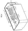
- FIG.4 is a perspective view of a control unit housing of the control unit of FIG. 1 ,
- FIG. 5 is a plan view of the closed control unit of FIG. 1 .
- FIG. 6 a - 6 b are sectional views of the control unit of FIG. 5 .
- FIG. 1 illustrates a control unit for use on the shock absorbers of a motor vehicle, which control unit regulates the flow of hydraulic liquid through a valve.
- the control unit has an integral pot-like housing 1 which is composed of plastic and is produced as an injection-molded part.
- the housing 1 is covered by a printed circuit board 2 which supports electrical components 4 which contain the regulation means for the shock absorber valve.
- the connection wires of the cables 5 , 6 , 7 which electrically connect the control unit to the surroundings extend through the contact openings 3 in the printed circuit board 2 .
- the line 5 is connected to a coil 8 which serves for inductive energy transfer of the valve (not illustrated any further).
- the housing 1 has seals 9 which are each pushed over a cable 5 , 6 , 7 and at the same time are inserted into the housing wall as part of the housing wall arrangement.
- the housing 1 is illustrated without the printed circuit board which simultaneously serves as a cover of the housing.
- Contact holders 10 , 11 , 12 are arranged in the interior of the housing, with the conductors 13 , 14 , 15 of the cable 6 being routed to the contact holder 10 , while the conductor 39 , 40 of the cable 7 are routed to the contact holders 11 , and the conductors 41 , 42 of the cable 5 are routed to the contact holder 12 .
- the further design of the contact holders 10 , 11 , 12 will be explained using the example of the contact holder 10 with the aid of FIG. 3 .
- the contact holder 10 has three openings 16 , 17 , 18 , with an inflexible press-in pin 19 , 20 , 21 being inserted into each opening in such a way that part of the press-in pin protrudes beyond the top of the contact holder 10 . These parts then engage in the contact openings 3 in the printed circuit board 2 .
- the press-in pins 19 , 20 , 21 also protrude beyond the lower face of the contact holder 10 and there are connected to the stripped part of the conductors 13 , 14 , 15 of the cable 6 .
- the lower end of the press-in pins 19 , 20 , 21 is spliced to the stripped end of the line 13 , 14 or 15 by a metal sheet 22 being wound around and pinching the two ends.
- FIG. 4 illustrates the pot-like housing 1 , with contact holder receptacles 24 and 25 being integrally formed from the housing on a side wall 23 .
- These contact holder receptacles have pegs 26 and 27 .
- These pegs 26 and 27 are integrally formed on a base 29 which is divided into various channels 30 , 31 , 32 by side walls 28 .
- an opening 33 for accommodating the seals 9 is visible in the side of the housing wall arrangement.
- FIG. 5 illustrates a plan view of the exemplary embodiment, with sectional directions Y and z being identified in particular, these directions being explained in greater detail in connection with FIG. 6 .
- FIG. 6 a shows a Y-Y section through the control unit.
- the contact holders 12 and 11 can be seen on said control unit, these contact holders each engaging in the printed circuit board 2 by means of the press-in pins 36 and 37 and, respectively, 34 and 35 , and in the process producing the electrical connection from the cables 5 and 7 to the components 4 .
- the press-in pins in the cable holder 12 or 11 can be populated as required. For example, no electrical line is fitted to the cable channel 31 , which is why the cable holder remains unpopulated at this point in this case.
- the cores 41 and 42 of the cable 5 adjoin the press-in pins 36 and 37 , whereas the cable 7 is routed to the press-in pins 34 and 35 of the contact holder 11 by means of the cores 39 and 40 .
- the Z-Z section illustrates the cable holder 11 which surrounds a peg 26 of the base 29 with the aid of a lug 43 and is therefore arrested against the housing wall arrangement 23 . It can also be seen here that the press-in pin 35 makes contact with the printed circuit board 2 .
Abstract
Description
Claims (11)
Applications Claiming Priority (7)
| Application Number | Priority Date | Filing Date | Title |
|---|---|---|---|
| DE102004057404 | 2004-11-26 | ||
| DE102004057404.9 | 2004-11-26 | ||
| DE102004057404 | 2004-11-26 | ||
| DE102004060694.3 | 2004-12-16 | ||
| DE102004060694 | 2004-12-16 | ||
| DE102004060694A DE102004060694A1 (en) | 2004-11-26 | 2004-12-16 | Electronic device |
| PCT/EP2005/055267 WO2006056512A1 (en) | 2004-11-26 | 2005-10-14 | Electronic device |
Publications (2)
| Publication Number | Publication Date |
|---|---|
| US20080081517A1 US20080081517A1 (en) | 2008-04-03 |
| US7722405B2 true US7722405B2 (en) | 2010-05-25 |
Family
ID=35472913
Family Applications (1)
| Application Number | Title | Priority Date | Filing Date |
|---|---|---|---|
| US11/791,551 Expired - Fee Related US7722405B2 (en) | 2004-11-26 | 2005-10-14 | Electronic device |
Country Status (6)
| Country | Link |
|---|---|
| US (1) | US7722405B2 (en) |
| EP (1) | EP1814764B8 (en) |
| JP (1) | JP4604091B2 (en) |
| DE (2) | DE102004060694A1 (en) |
| ES (1) | ES2306220T3 (en) |
| WO (1) | WO2006056512A1 (en) |
Cited By (12)
| Publication number | Priority date | Publication date | Assignee | Title |
|---|---|---|---|---|
| US9150077B2 (en) | 2009-10-06 | 2015-10-06 | Tenneco Automotive Operating Company Inc. | Damper with digital valve |
| US9163691B2 (en) | 2013-03-15 | 2015-10-20 | Tenneco Automotive Operating Company Inc. | Rod guide arrangement for electronically controlled valve applications |
| US9217483B2 (en) | 2013-02-28 | 2015-12-22 | Tenneco Automotive Operating Company Inc. | Valve switching controls for adjustable damper |
| US9399383B2 (en) | 2013-02-28 | 2016-07-26 | Tenneco Automotive Operating Company Inc. | Damper with integrated electronics |
| US9404551B2 (en) | 2013-03-15 | 2016-08-02 | Tenneco Automotive Operating Company Inc. | Rod guide assembly with multi-piece valve assembly |
| US9879748B2 (en) | 2013-03-15 | 2018-01-30 | Tenneco Automotive Operating Company Inc. | Two position valve with face seal and pressure relief port |
| US9879746B2 (en) | 2013-03-15 | 2018-01-30 | Tenneco Automotive Operating Company Inc. | Rod guide system and method with multiple solenoid valve cartridges and multiple pressure regulated valve assemblies |
| US9884533B2 (en) | 2013-02-28 | 2018-02-06 | Tenneco Automotive Operating Company Inc. | Autonomous control damper |
| US9954411B2 (en) | 2012-11-02 | 2018-04-24 | Siemens Schweiz Ag | Actuating drive having an electrical plug-in connection |
| US10312609B2 (en) * | 2015-06-03 | 2019-06-04 | 3M Innovative Properties Company | Low profile electrical connector |
| US10479160B2 (en) | 2017-06-06 | 2019-11-19 | Tenneco Automotive Operating Company Inc. | Damper with printed circuit board carrier |
| US10588233B2 (en) | 2017-06-06 | 2020-03-10 | Tenneco Automotive Operating Company Inc. | Damper with printed circuit board carrier |
Families Citing this family (6)
| Publication number | Priority date | Publication date | Assignee | Title |
|---|---|---|---|---|
| JP2009134932A (en) * | 2007-11-29 | 2009-06-18 | Fujitsu Ltd | Electronic device and printed board unit |
| DE102009043702B4 (en) * | 2009-10-01 | 2019-02-28 | Unimet Gmbh | System of at least one press-in contact and a press-fit contact housing and method for producing the same |
| DE102013004189B4 (en) | 2013-03-12 | 2019-07-18 | Sew-Eurodrive Gmbh & Co Kg | Electric device with housing and cover which can be placed on the housing |
| DE102013113200A1 (en) * | 2013-11-28 | 2015-05-28 | Huf Hülsbeck & Fürst Gmbh & Co. Kg | Housing for at least one electrical component |
| JP6687291B1 (en) * | 2019-01-22 | 2020-04-22 | 三菱電機株式会社 | Electrical equipment |
| CN110252034B (en) * | 2019-05-10 | 2021-07-06 | 太原理工大学 | Biological 3D prints toilet's fungus degree control and monitoring system |
Citations (12)
| Publication number | Priority date | Publication date | Assignee | Title |
|---|---|---|---|---|
| US4813885A (en) | 1988-06-29 | 1989-03-21 | Molex Incorporated | Wiring harness connector retainer |
| GB2263817A (en) | 1992-01-29 | 1993-08-04 | Mecanismos Aux Ind | Process for the production of service boxes for vehicles |
| US5295859A (en) * | 1991-10-23 | 1994-03-22 | Hirose Electric Co., Ltd. | Electric connector |
| US5445528A (en) | 1994-05-31 | 1995-08-29 | The Whitaker Corporation | Electrical connector with improved mounting |
| DE19503778A1 (en) | 1995-02-04 | 1996-08-08 | Duerrwaechter E Dr Doduco | Housing and mounting system for electronic circuit boards and feed lines |
| DE19632817A1 (en) | 1995-08-15 | 1997-02-20 | Whitaker Corp | Electrical cable tree for multi-port electrical device |
| US6039582A (en) | 1998-09-30 | 2000-03-21 | Motorola, Inc. | Discharge lamp ballast housing with solderless connectors |
| US6160708A (en) | 1998-06-15 | 2000-12-12 | Siemens Aktiengesellschaft | Control unit for a motor vehicle |
| US6193564B1 (en) | 1998-04-17 | 2001-02-27 | Siemens Aktiengesellschaft | Electric connecting configuration |
| US6386917B1 (en) * | 1999-02-25 | 2002-05-14 | Yazaki Corporation | Wire module and method of producing same |
| US20020149916A1 (en) | 2000-05-11 | 2002-10-17 | Juergen Kurle | Electronic device |
| US20040161975A1 (en) | 2003-02-07 | 2004-08-19 | Shuhei Sakai | Power supply terminal |
Family Cites Families (4)
| Publication number | Priority date | Publication date | Assignee | Title |
|---|---|---|---|---|
| JPS541894A (en) * | 1977-06-08 | 1979-01-09 | Yamaichi Electric Mfg | Connector for flexible flat cable |
| JPS5979981A (en) * | 1982-10-29 | 1984-05-09 | 松下電器産業株式会社 | Electric connector |
| JPH04123487A (en) * | 1990-09-14 | 1992-04-23 | Hitachi Ltd | Electronic device and its preparation |
| JP3631868B2 (en) * | 1996-12-20 | 2005-03-23 | 株式会社東芝 | Motion vector detection apparatus and method |
-
2004
- 2004-12-16 DE DE102004060694A patent/DE102004060694A1/en not_active Withdrawn
-
2005
- 2005-10-14 US US11/791,551 patent/US7722405B2/en not_active Expired - Fee Related
- 2005-10-14 JP JP2007541896A patent/JP4604091B2/en not_active Expired - Fee Related
- 2005-10-14 ES ES05794598T patent/ES2306220T3/en active Active
- 2005-10-14 DE DE502005003875T patent/DE502005003875D1/en active Active
- 2005-10-14 WO PCT/EP2005/055267 patent/WO2006056512A1/en active IP Right Grant
- 2005-10-14 EP EP05794598A patent/EP1814764B8/en not_active Expired - Fee Related
Patent Citations (15)
| Publication number | Priority date | Publication date | Assignee | Title |
|---|---|---|---|---|
| US4813885A (en) | 1988-06-29 | 1989-03-21 | Molex Incorporated | Wiring harness connector retainer |
| EP0349125A2 (en) | 1988-06-29 | 1990-01-03 | Molex Incorporated | Wiring harness connector retainer |
| US5295859A (en) * | 1991-10-23 | 1994-03-22 | Hirose Electric Co., Ltd. | Electric connector |
| GB2263817A (en) | 1992-01-29 | 1993-08-04 | Mecanismos Aux Ind | Process for the production of service boxes for vehicles |
| DE4208765A1 (en) | 1992-01-29 | 1993-08-05 | Mecanismos Aux Ind | ELECTRICAL CONTROL BOX AND MANUFACTURING METHOD |
| US5445528A (en) | 1994-05-31 | 1995-08-29 | The Whitaker Corporation | Electrical connector with improved mounting |
| DE19503778A1 (en) | 1995-02-04 | 1996-08-08 | Duerrwaechter E Dr Doduco | Housing and mounting system for electronic circuit boards and feed lines |
| DE19632817A1 (en) | 1995-08-15 | 1997-02-20 | Whitaker Corp | Electrical cable tree for multi-port electrical device |
| US5836789A (en) | 1995-08-15 | 1998-11-17 | The Whitaker Corporation | Multi port electrical device and harness therefor |
| US6193564B1 (en) | 1998-04-17 | 2001-02-27 | Siemens Aktiengesellschaft | Electric connecting configuration |
| US6160708A (en) | 1998-06-15 | 2000-12-12 | Siemens Aktiengesellschaft | Control unit for a motor vehicle |
| US6039582A (en) | 1998-09-30 | 2000-03-21 | Motorola, Inc. | Discharge lamp ballast housing with solderless connectors |
| US6386917B1 (en) * | 1999-02-25 | 2002-05-14 | Yazaki Corporation | Wire module and method of producing same |
| US20020149916A1 (en) | 2000-05-11 | 2002-10-17 | Juergen Kurle | Electronic device |
| US20040161975A1 (en) | 2003-02-07 | 2004-08-19 | Shuhei Sakai | Power supply terminal |
Non-Patent Citations (2)
| Title |
|---|
| International Search Report issued in a corresponding foreign application. |
| Written Report dated Jan. 3, 2006 issued in corresponding application 2004P19942WO. |
Cited By (17)
| Publication number | Priority date | Publication date | Assignee | Title |
|---|---|---|---|---|
| US9150077B2 (en) | 2009-10-06 | 2015-10-06 | Tenneco Automotive Operating Company Inc. | Damper with digital valve |
| US9695900B2 (en) | 2009-10-06 | 2017-07-04 | Tenneco Automotive Operating Company Inc. | Damper with digital valve |
| US9810282B2 (en) | 2009-10-06 | 2017-11-07 | Tenneco Automotive Operating Company Inc. | Damper with digital valve |
| US9954411B2 (en) | 2012-11-02 | 2018-04-24 | Siemens Schweiz Ag | Actuating drive having an electrical plug-in connection |
| US9884533B2 (en) | 2013-02-28 | 2018-02-06 | Tenneco Automotive Operating Company Inc. | Autonomous control damper |
| US10000104B2 (en) | 2013-02-28 | 2018-06-19 | Tenneco Automotive Operating Company Inc. | Damper with integrated electronics |
| US9217483B2 (en) | 2013-02-28 | 2015-12-22 | Tenneco Automotive Operating Company Inc. | Valve switching controls for adjustable damper |
| US9399383B2 (en) | 2013-02-28 | 2016-07-26 | Tenneco Automotive Operating Company Inc. | Damper with integrated electronics |
| US9802456B2 (en) | 2013-02-28 | 2017-10-31 | Tenneco Automotive Operating Company Inc. | Damper with integrated electronics |
| US9925842B2 (en) | 2013-02-28 | 2018-03-27 | Tenneco Automotive Operating Company Inc. | Valve switching controls for adjustable damper |
| US9404551B2 (en) | 2013-03-15 | 2016-08-02 | Tenneco Automotive Operating Company Inc. | Rod guide assembly with multi-piece valve assembly |
| US9879746B2 (en) | 2013-03-15 | 2018-01-30 | Tenneco Automotive Operating Company Inc. | Rod guide system and method with multiple solenoid valve cartridges and multiple pressure regulated valve assemblies |
| US9879748B2 (en) | 2013-03-15 | 2018-01-30 | Tenneco Automotive Operating Company Inc. | Two position valve with face seal and pressure relief port |
| US9163691B2 (en) | 2013-03-15 | 2015-10-20 | Tenneco Automotive Operating Company Inc. | Rod guide arrangement for electronically controlled valve applications |
| US10312609B2 (en) * | 2015-06-03 | 2019-06-04 | 3M Innovative Properties Company | Low profile electrical connector |
| US10479160B2 (en) | 2017-06-06 | 2019-11-19 | Tenneco Automotive Operating Company Inc. | Damper with printed circuit board carrier |
| US10588233B2 (en) | 2017-06-06 | 2020-03-10 | Tenneco Automotive Operating Company Inc. | Damper with printed circuit board carrier |
Also Published As
| Publication number | Publication date |
|---|---|
| ES2306220T3 (en) | 2008-11-01 |
| EP1814764B8 (en) | 2008-06-25 |
| JP4604091B2 (en) | 2010-12-22 |
| DE502005003875D1 (en) | 2008-06-05 |
| WO2006056512A1 (en) | 2006-06-01 |
| DE102004060694A1 (en) | 2006-06-14 |
| US20080081517A1 (en) | 2008-04-03 |
| EP1814764B1 (en) | 2008-04-23 |
| EP1814764A1 (en) | 2007-08-08 |
| JP2008522390A (en) | 2008-06-26 |
Similar Documents
| Publication | Publication Date | Title |
|---|---|---|
| US7722405B2 (en) | Electronic device | |
| EP3301763B1 (en) | Electronic device | |
| CN102842872B (en) | Electrical terminal block | |
| US6547572B1 (en) | Integrated and flexible power distribution assembly | |
| US5325267A (en) | Remote driver board having input/output connector circuitry molded therein | |
| US5040996A (en) | Central circuit arrangement for motor vehicles | |
| CN101316032A (en) | Electrical junction box | |
| JPH0373505B2 (en) | ||
| EP1737286A2 (en) | Sealed fastenerless multi-board electronic module and method of manufacture | |
| EP1641081B1 (en) | Press-fit terminal, printed board connection structure using the press-fit terminal, and electrical connection box | |
| EP1669247A2 (en) | Electric connection box | |
| EP3249675A2 (en) | Modular fuse holder and arrangement and connection thereof | |
| EP1245454B1 (en) | Junction box | |
| CN109841992B (en) | Modular plug connector with replaceable module circuit board | |
| US6511331B2 (en) | Electrical junction box for a vehicle | |
| US7674127B2 (en) | Electrical contact-making element | |
| CN108281930B (en) | Arrangement structure of electrical connection box, wire harness, and vehicle | |
| US5653018A (en) | Method for the manufacture of an electric appliance | |
| EP1548893B1 (en) | Connecting a solenoid to a lead frame | |
| US9017094B2 (en) | Coupling structure for a flat wiring cable having non-uniform pitch | |
| CN111406140A (en) | Vehicle door handle | |
| CN1955454B (en) | Electronic circuit unit | |
| CN100460248C (en) | Electronic device | |
| KR20180051943A (en) | Elctronic control device | |
| KR100812786B1 (en) | Junction box |
Legal Events
| Date | Code | Title | Description |
|---|---|---|---|
| AS | Assignment |
Owner name: SIEMENS AKTIENGESELLSCHAFT, GERMANY Free format text: ASSIGNMENT OF ASSIGNORS INTEREST;ASSIGNORS:JAKLIN, RALF;ULLRICH, HORST;REEL/FRAME:019392/0525 Effective date: 20070425 Owner name: SIEMENS AKTIENGESELLSCHAFT,GERMANY Free format text: ASSIGNMENT OF ASSIGNORS INTEREST;ASSIGNORS:JAKLIN, RALF;ULLRICH, HORST;REEL/FRAME:019392/0525 Effective date: 20070425 |
|
| FEPP | Fee payment procedure |
Free format text: PAYOR NUMBER ASSIGNED (ORIGINAL EVENT CODE: ASPN); ENTITY STATUS OF PATENT OWNER: LARGE ENTITY |
|
| AS | Assignment |
Owner name: CONTINENTAL AUTOMOTIVE GMBH, GERMANY Free format text: ASSIGNMENT OF ASSIGNORS INTEREST;ASSIGNOR:SIEMENS AKTIENGESELLSCHAFT;REEL/FRAME:027263/0068 Effective date: 20110704 |
|
| REMI | Maintenance fee reminder mailed | ||
| LAPS | Lapse for failure to pay maintenance fees | ||
| STCH | Information on status: patent discontinuation |
Free format text: PATENT EXPIRED DUE TO NONPAYMENT OF MAINTENANCE FEES UNDER 37 CFR 1.362 |
|
| FP | Lapsed due to failure to pay maintenance fee |
Effective date: 20140525 |