US7720996B2 - Internet protocol (IP) address proximity and application to peer provider location - Google Patents
Internet protocol (IP) address proximity and application to peer provider location Download PDFInfo
- Publication number
- US7720996B2 US7720996B2 US09/908,782 US90878201A US7720996B2 US 7720996 B2 US7720996 B2 US 7720996B2 US 90878201 A US90878201 A US 90878201A US 7720996 B2 US7720996 B2 US 7720996B2
- Authority
- US
- United States
- Prior art keywords
- address
- peer
- addresses
- peers
- information
- Prior art date
- Legal status (The legal status is an assumption and is not a legal conclusion. Google has not performed a legal analysis and makes no representation as to the accuracy of the status listed.)
- Expired - Fee Related, expires
Links
Images


Classifications
-
- H—ELECTRICITY
- H04—ELECTRIC COMMUNICATION TECHNIQUE
- H04L—TRANSMISSION OF DIGITAL INFORMATION, e.g. TELEGRAPHIC COMMUNICATION
- H04L9/00—Cryptographic mechanisms or cryptographic arrangements for secret or secure communications; Network security protocols
- H04L9/40—Network security protocols
-
- H—ELECTRICITY
- H04—ELECTRIC COMMUNICATION TECHNIQUE
- H04L—TRANSMISSION OF DIGITAL INFORMATION, e.g. TELEGRAPHIC COMMUNICATION
- H04L61/00—Network arrangements, protocols or services for addressing or naming
-
- H—ELECTRICITY
- H04—ELECTRIC COMMUNICATION TECHNIQUE
- H04L—TRANSMISSION OF DIGITAL INFORMATION, e.g. TELEGRAPHIC COMMUNICATION
- H04L61/00—Network arrangements, protocols or services for addressing or naming
- H04L61/35—Network arrangements, protocols or services for addressing or naming involving non-standard use of addresses for implementing network functionalities, e.g. coding subscription information within the address or functional addressing, i.e. assigning an address to a function
-
- H—ELECTRICITY
- H04—ELECTRIC COMMUNICATION TECHNIQUE
- H04L—TRANSMISSION OF DIGITAL INFORMATION, e.g. TELEGRAPHIC COMMUNICATION
- H04L61/00—Network arrangements, protocols or services for addressing or naming
- H04L61/45—Network directories; Name-to-address mapping
-
- H—ELECTRICITY
- H04—ELECTRIC COMMUNICATION TECHNIQUE
- H04L—TRANSMISSION OF DIGITAL INFORMATION, e.g. TELEGRAPHIC COMMUNICATION
- H04L67/00—Network arrangements or protocols for supporting network services or applications
- H04L67/01—Protocols
- H04L67/10—Protocols in which an application is distributed across nodes in the network
- H04L67/1001—Protocols in which an application is distributed across nodes in the network for accessing one among a plurality of replicated servers
- H04L67/1004—Server selection for load balancing
- H04L67/1021—Server selection for load balancing based on client or server locations
-
- H—ELECTRICITY
- H04—ELECTRIC COMMUNICATION TECHNIQUE
- H04L—TRANSMISSION OF DIGITAL INFORMATION, e.g. TELEGRAPHIC COMMUNICATION
- H04L67/00—Network arrangements or protocols for supporting network services or applications
- H04L67/01—Protocols
- H04L67/10—Protocols in which an application is distributed across nodes in the network
- H04L67/104—Peer-to-peer [P2P] networks
- H04L67/1061—Peer-to-peer [P2P] networks using node-based peer discovery mechanisms
- H04L67/1063—Discovery through centralising entities
-
- H—ELECTRICITY
- H04—ELECTRIC COMMUNICATION TECHNIQUE
- H04L—TRANSMISSION OF DIGITAL INFORMATION, e.g. TELEGRAPHIC COMMUNICATION
- H04L67/00—Network arrangements or protocols for supporting network services or applications
- H04L67/01—Protocols
- H04L67/10—Protocols in which an application is distributed across nodes in the network
- H04L67/104—Peer-to-peer [P2P] networks
- H04L67/1061—Peer-to-peer [P2P] networks using node-based peer discovery mechanisms
- H04L67/1072—Discovery involving ranked list compilation of candidate peers
-
- H—ELECTRICITY
- H04—ELECTRIC COMMUNICATION TECHNIQUE
- H04L—TRANSMISSION OF DIGITAL INFORMATION, e.g. TELEGRAPHIC COMMUNICATION
- H04L69/00—Network arrangements, protocols or services independent of the application payload and not provided for in the other groups of this subclass
- H04L69/30—Definitions, standards or architectural aspects of layered protocol stacks
- H04L69/32—Architecture of open systems interconnection [OSI] 7-layer type protocol stacks, e.g. the interfaces between the data link level and the physical level
- H04L69/322—Intralayer communication protocols among peer entities or protocol data unit [PDU] definitions
- H04L69/329—Intralayer communication protocols among peer entities or protocol data unit [PDU] definitions in the application layer [OSI layer 7]
Definitions
- the present invention relates to the field of networking. More specifically, the present invention relates to methods and systems associated with detecting the proximity of IP (Internet Protocol) addresses, and their applications to locating peer providers of resources.
- IP Internet Protocol
- Interactions that are better carried out in a peer-to-peer fashion include the transfer of large volumes of data (such as images, music files, or video clips) or highly volatile information (such as documents being edited by several people at once), and distributed applications that run on multiple end-user machines (such as real-time distributed games).
- Peer-to-peer computing enables three novel aspects that are not supported by the World Wide Web:
- One of the most promising benefits of the peer-to-peer model is the ability to seamlessly “cache” resources on multiple machines, both to provide robustness against one particular source of content going off-line, and to maximize the download performance by transparently selecting the fastest and closest possible source(s) of a download and by striping across multiple “equivalent” sources, i.e., downloading multiple fragments (or stripes) of the same file from several sources at once.
- one of the problems faced by such peer-to-peer infrastructure is to be able to find the sources of a given content that are the “closest” to a given target in terms of Internet topology, in order to maximize bandwidth and minimize latency.
- the question of interest is to find the best source or sources, rather than the best route.
- the difficulty of the problem stems from the fact that it is in general not possible to have exact knowledge of the network topology, in particular of the topology of the network below the level of Autonomous Systems (ASs).
- ASs Autonomous Systems
- Border Gateway Protocol which is used by routers to compute the best route between two published networks.
- BGP Border Gateway Protocol
- IP address assignment information is collected from Address Allocation Tables (AATs) of a plurality of IP address assigning registrars.
- AATs Address Allocation Tables
- the information is processed and stored into one or more data structures.
- the information is accessed to determine a proximity measure for two IP addresses.
- the proximity determination includes the determination of superblock memberships of the IP addresses, comparison of the assigning registrars, as well as the location countries of the IP addresses.
- the proximity detection is applied to locating IP addresses of peer providers of resources.
- Autonomous System (AS) numbers and IP addresses for a plurality of peer providers for a plurality of resources are also collected and organized into one or more data structures; this organized information of the peer providers is also used in locating the “closest” peer providers of a resource in terms of network topology.
- AS Autonomous System
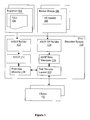
- FIG. 1 illustrates an overview of the present invention, in accordance with one embodiment
- FIG. 2 illustrates the operational flow of the relevant aspects of the Allocated Address Lookup Structure (AALS) builder of FIG. 1 , in accordance with one embodiment;
- AALS Allocated Address Lookup Structure
- FIGS. 3 a - 3 b illustrate two example data structures suitable for use to implement the AALS of FIG. 1 , in accordance with one embodiment
- FIG. 4 illustrates the operational flow of the relevant aspects of the AS/IP data structure builder of FIG. 1 , in accordance with one embodiment
- FIG. 5 illustrates an example data structure suitable for use to implement the AS/IP data structure of FIG. 1 , in accordance with one embodiment
- FIG. 6 a - 6 b illustrate the operational flow of the relevant aspects of the proximity detector of FIG. 1 , in accordance with two embodiments;
- FIGS. 7 a - 7 c illustrate the operational flow of the relevant aspects of the peer provider locator of FIG. 1 , in accordance with one embodiment
- FIG. 8 illustrates the operational flow of the client of FIG. 1 , in accordance with one embodiment
- FIG. 9 illustrates an example computer system suitable for use to practice the present invention, in accordance with one embodiment.
- the present invention includes improved methods and related apparatuses for detecting the proximity of two IP addresses, and its application to locating the “closest” peer providers of resources based on network topology.
- “Closest”, in the context of present application, is a qualitative attribute of the relative network distance between two peer providers as seen by the methodology of the present invention, which may or may not correspond in absolute distance to either the shortest physical distance, the smallest number of network hops, the shortest network latency, or any other similar measure.
- processor includes microprocessors, micro-controllers, digital signal processors, and the like, that are standalone, adjunct or embedded.
- FIG. 1 wherein a block diagram illustrating an overview of the present invention, in accordance with one embodiment, is shown.
- IPAP detection system 110 of the present invention includes AALS builder 112 and proximity detector 120 .
- AALS builder 112 accesses and retrieves IP address assignment information from IP address assigning registrars 102 , and builds AALS data structures 114 , for use during operation by proximity detector 120 , to quickly and efficiently detect the proximity of any two given IP addresses.
- IPAP detection system 110 also includes Autonomous System AS/IP data structure builder 116 and peer provider locator 122 .
- AS/IP data structure builder 116 builds up AS/IP data structures 118 based on AS and IP addresses of peer providers of various resources of interest, for use during operation by peer provider locator 122 to locate and provide a client (such as one of clients 132 ) with a list of proximally located peer providers of any given resource of interest, including the locations, more specifically, the IP addresses of the peer providers.
- Peer provider locator 122 advantageously utilizes proximity detector 120 in detecting the proximity of two IP addresses.
- registrars 102 including AATs 104 contained therein, and router groups 106 , including AS numbers 108 contained therein, all represent a broad range of such elements known in the art.
- clients 132 also represent a broad range of such elements, including but are not limited to, wireless palm sized personal devices (such as wireless mobile phones, pagers, personal digital assistants (PDAs)), notebook computers, desktop computers, set-top boxes, servers (such as compute servers, and file servers), network appliances, network attached storage, and so forth.
- IPAP detection system 110 may be implemented on one or more servers.
- the various elements are communicatively coupled to each other through interconnected public networks, such as the Internet, and communicate with each other using the IP (although some of the elements may be coupled to each other via private networking connection and/or utilizing proprietary communication protocols).
- AALS builder 112 selects an IP address assigning registrar, block 202 , and accesses its AAT to retrieve IP address assignment information from the registrar, block 204 .
- AALS builder 112 retrieves information about all superblocks of IP addresses (hereinafter, simply called superblocks) assigned by the registrar. For each superblock, AALS builder 112 retrieves the country identifications for the countries within which the superblock addresses reside, and the community identifier of the superblock.
- AALS builder 112 sort/merges the retrieved superblocks of IP addresses, based on their base block IP addresses, into MLS 114 , block 206 , for subsequent use by proximity detector 120 in detecting or determining the proximity of two IP addresses.
- blocks 202 - 206 are repeated for all known registrars, until eventually, it is determined in block 208 , that all known registrars have been accessed, and their address assignment information have been retrieved and stored into AALS 114 .
- the MLS data structure can be built by merging the information as it is retrieved, or by batch-sorting the information after all information has been retrieved. Further, as registrars change or make new IP address assignments from time to time, the presently preferred embodiment repeats the above described AALS building process from time to time. The frequency of repetition is dependent on the accuracy desired for the proximity detection process. Preferably, the frequency is configurable by the service provider hosting IPAP detection system 110 . Such configuration may be effectuated via any one of a number of user configuration techniques known in the art.
- AALS 114 is simply formed by arranging the superblocks in accordance with their base addresses.
- the data structure may be subsequently accessed using a “binary search” strategy.
- FIGS. 3 a - 3 b illustrate two alternative data structures also suitable for use to store the retrieved address assignment information in an organized manner, to facilitate efficient proximity detection.
- the retrieved address assignment information is stored and organized in a “prefix tree” data structure, with the registrar, country, and community information 306 a - 310 a of each superblock of IP addresses being stored at a “leaf node” location of the “prefix tree” data structure.
- the “leaf node” location is determined by the values of the significant bits of the IP addresses of the superblock, starting with the most significant bit from the root.
- the number of most significant bits that uniquely distinguishes a given superblock from any other superblock stored in the AALS also determines the depth level of the “leaf node” corresponding to the given superblock.
- the first significant bit of the IP addresses of a superblock is “0” (branch 310 a ) (branch 310 a ), its “leaf node” is disposed at the left-hand-side (LHS) of the “prefix tree”. If the first significant bit of the IP addresses of a superblock is “1” (branch 310 b), its “leaf node” is disposed at the right-hand-side (RHS) of the “prefix tree”.
- the “lower levels” of the “prefix tree” are traversed in like manner to locate the ultimate “leaf node” storage location for a superblock. Thus, if a superblock does not exist (i.e.
- the IP addresses have not been assigned by any of the registrars, the corresponding “leaf node” will be missing, as the “leaf node” for the exemplary superblock having “10” as its two most significant bits (end of branch 310 c missing a “leaf node”).
- FIG. 3 b illustrates an alternate embodiment, wherein the entire “prefix tree” is subdivided into a number of smaller “prefix trees” 340 a - 340 k (a “hybrid” implementation).
- the smaller “prefix trees” 340 a - 340 k are indexed by the first n most significant bits of the superblock base IP address, where n is a power of two.
- the integer value of these first n bits is shown as numbers 320 a - 320 k in FIG. 3 b , and ranges from 0 to one less than two raised to the nth power. For the illustrated embodiment, n equals 8.
- the n most significant bits of the address are first used to select the smaller “prefix trees” whose index corresponds to these bits. Subsequently, the selected smaller “prefix tree” is constructed as described above, using the remaining s-n bits of the superblock base IP address, where s is the size of the superblock IP address in bits. For IPv4 superblock addresses, the size s is 32 bits.
- the above illustrated exemplary data structures are particularly suitable in facilitating quick lookup of superblock registrar and country information, starting with a given IP address.
- other data structures may also employed to store the registrar, country, and community information of the superblock IP addresses.
- other differentiating information may also be employed and stored.
- proximity detector 120 upon invocation to determine or detect the proximity of two given IP addresses, proximity detector 120 first accesses AALS 114 to determine the superblock memberships of the IP addresses of interest, block 602 .
- a penalty is optionally assessed and the proximity detection process jumps to block 610 (to be described more fully later). In one embodiment, the penalty would be assessed by multiplying the distance metric computed in block 610 by eight and adding sixteen.
- the proximity detection process continues at block 604 , wherein the registrars and country codes corresponding to the two superblocks of IP addresses are first fetched from the MLS Data Structure shown in two embodiments in FIG. 3 a and FIG. 3 b , respectively. The registrars are then compared. If the registrars corresponding to the two superblocks of IP addresses are determined to be different, a “large penalty” is assessed against the proximity or distance metric to be subsequently generated, block 605 . In one embodiment, a penalty of 256 is assessed.
- the proximity detection process continues at block 606 , wherein the countries within which the two superblocks of IP addresses are located, are compared. If the countries are determined to be different, a “medium penalty” is assessed against the proximity or distance metric to be subsequently generated, block 607 . In one embodiment, a penalty of 128 is assessed.
- the proximity detection process continues at block 608 , wherein the two superblocks themselves are compared. If the two superblocks are determined to be different, a “small penalty” is assessed against the proximity or distance metric to be subsequently generated, block 609 . In one embodiment, a penalty of 64 is assessed.
- the proximity detection process continues at block 610 , wherein the bits of the two IP addresses are compared, starting from the most significant bit to the least significant bit, to determine the first bit positions the two IP addresses begin to diverge or differ.
- the proximity or distance metric is then generated based on the position where the bits of the two IP addresses begin to diverge, block 612 .
- the distance metric is set to be the number of bits from the first differing bit to the least significant bit. For the earlier cases, where penalties are assessed, the corresponding penalty is outputted as the proximity or distance measure.
- an additional penalty can be assessed in block 612 based on the superblock community information contained in the AALS data structures 114 . If, by advantageously using the AALS data structures 114 , the two IP addresses are found to have different AS numbers, an additional “large penalty” can be assessed. In one alternate embodiment, this additional “large penalty” would be 32. If, however, the AS numbers, although different, are found to belong to the same community (as defined in the BGP protocol), an additional “small penalty” is assessed. In one alternate embodiment, the additional “small penalty” would be 16. If the two IP addresses are found to have the save AS numbers, no additional penalty is assessed.
- FIG. 6 b illustrates the operational flow for an alternate embodiment of proximity detector 120 , operating inside a private, e.g. corporate, network behind a Network Address Translator (NAT) firewall or proxy.
- proximity detector 120 can be configured to assess different penalties depending on whether both IP addresses are inside the private network or not, block 622 . If both IP addresses are inside the private network, block 624 , process 600 of FIG. 6 a is performed, starting at block 610 . That is, only the distance determined in block 610 is used for proximity detection, but no other penalties are assessed. If one of the IP addresses is inside the private network, but the other one is outside, the outside IP address of the gateway is first substituted for the local IP address before process 600 of FIG. 6 a is performed, starting from the beginning. If both IP addresses are outside the private network, process 600 of FIG. 6 a is performed as discussed above.
- NAT Network Address Translator
- the proximity determination process described above may be implemented very efficiently as one AALS lookup per address, followed by simple comparisons, binary masks, and binary shifts.
- To lookup which superblock a given IP address belongs to the largest base address (of a superblock in the AALS) that is smaller than or equal to the IP address is first determined. For the earlier described “first embodiment”, this may be achieved quickly through binary search of the sorted list of the superblocks, and checking whether the superblock thus located does indeed match the IP address for that block's number of significant bits. The contrary would indicate that the IP address is not in any existing (i.e. known) superblock.
- prefix tree this may be achieved by descending the prefix tree along the path of nodes that match the successive bits of the IP address, from most significant to least significant, until a leaf node is reached or no laid path can be found (which would indicate that the IP address is not in any known superblock).
- the first few bits of the address are used to select the appropriate prefix tree, which is then used as above for the remaining bits.
- the efficiency of the lookups depends on the chosen implementation for the AALS.
- the “binary search” implementation is expected to yield a uniform cost of lookup, requiring a number of 32-bit comparisons equal to the base-2 logarithm of the total number of superblocks in the AALS.
- a lookup requires a number of 1-bit comparisons equal to the number of significant bits (and thus, the category) of the superblock to which the IP address belongs. Since large superblocks of the lower categories contain many more addresses than the higher category ones, the “prefix tree” implementation is likely to have the advantage that the most frequent lookups will also be the fastest lookups.
- the “prefix tree” achieves the smallest expected number of binary comparisons.
- the “hybrid” implementation is expected to attain even better performance by resolving the first few bits of the IP address using a single indexing operation into a table. For example, if 12 bits are used for the first level of the hybrid method, the superblock containing a given IP address will be determined in a single step if the superblock is of class/12 or less. Since the address belonging to the largest blocks are also the most frequent ones, the average savings are very significant.
- IPAP detection system 110 in addition to the teachings of the present invention for detecting IP address proximity, is further incorporated with the teachings of the present invention to apply the IP address proximity detection technology to providing a client with a list of proximally located peer providers for resources of interest. To that end, IPAP detection system 110 is further equipped with AS/IP data structure builder 106 and peer provider locator 122 .
- AS/IP data structure builder 116 upon receipt of each registration of a peer provider 132 of a given resource, block 402 , AS/IP data structure builder 116 , as part of the registration process, obtains the IP address of the peer provider 132 , block 404 .
- this IP address is obtained from the peer provider itself.
- this IP address is obtained as a parameter of the network connection between the peer provider 132 and IPAP detection system 110 .
- AS/IP data structure builder 116 determines the AS number of peer provider, block 404 .
- AS/IP data structure builder 116 obtains the AS number information by using aBGP feed.
- AS/IP data structure builder 116 uses information supplied by the administrator of the IPAP detection system 110 to compute AS numbers; this information in turn can, but need not necessarily, be derived from a BGP feed.
- the AS number is supplied by the peer provider 132 itself.
- AS/IP data structure builder 116 stores the obtained IP address and AS numbers information in the earlier mentioned AS/IP data structures 118 , for subsequent user by peer provider locator 122 during operation.
- FIG. 5 wherein a block diagram illustrating a collection of data structures suitable for use to store the AS numbers and the IP addresses of the peer providers of various resources of interest, in accordance with one embodiment, is shown.
- the data structures shown in the block diagram facilitate efficient retrieval of peer provider IP addresses of proximally located peer providers, given a specified resource.
- AS/IP data structures 500 include table 502 having a number of columns 504 - 506 for storing resource identifiers identifying the various resources whose peer providers are tracked, column 504 , and references to the bucket tables 512 , column 506 .
- AS/IP data structures 500 also include bucket tables 512 having a number of columns 514 - 516 for storing AS numbers of the peer providers, column 514 , and pointers to IP address lists within the AS number buckets, column 516 .
- the IP addresses of the peer providers are organized by the peer providers' AS numbers.
- each IP address list 522 for an AS number includes one or more IP addresses of peer providers “linked” together for retrieval (ref. 524 and 526 ), with the last IP address having an associated “end of list” (EOL) marker (or a null value).
- peer provider locator 122 upon requested by a client 132 to provide a desired number of peer providers for a specified target resource, peer provider locator 122 first determines the AS number of the requesting client 132 , block 702 .
- peer provider locator 122 extracts the AS number of requesting client 132 from the received communication and determines the AS number of requesting client 132 by using the AS/IP data structures 118 that have been previously constructed by the AS/IP data structure builder 116 .
- the AS number is part of the communication through which the request is conveyed to IPAP detection system 110 .
- the system is used to retrieve a number of addresses satisfying a particular condition (such as serving a copy of a particular resource in a peer-to-peer architecture), such that the addresses are proximal, in terms of Internet topology and efficiency, to a given target IP address.
- a particular condition such as serving a copy of a particular resource in a peer-to-peer architecture
- the addresses are proximal, in terms of Internet topology and efficiency, to a given target IP address.
- the target IP address will be that of a peer wishing to access a particular resource; the retrieved addresses will correspond to the IP addresses of peers which can supply the desired resource.
- the desired number of peer providers to be returned is specified in the request. In another embodiment, the desired number of peer providers to be returned is implicitly specified via a configurable parameter of the requesting client and/or IPAP detection system 110 . In the cases where both the requesting client and IPAP detection system 110 specify the desired number, either may control, depending on the implementation.
- peer provider locator 122 accesses AS/IP data structures 118 and attempts to retrieve the IP addresses of the peer providers of the target resource of interest with the same AS number as that of the requesting client 132 , as determined in block 702 .
- peer provider locator 122 determines if it was successful in retrieving a number of IP addresses of the peer providers of the target resource of interest that meets or is in excess of the desired number of IP addresses of peer providers to be returned.
- peer provider locator 122 determines the proximity of the retrieved IP addresses to the IP address of the requesting client 132 , block 708 .
- peer provider locator 122 advantageously determines the proximity of the retrieved IP addresses by invoking proximity detector 120 .
- the information about whether the IP addresses share the same AS number, as well as other relevant information may be provided to proximity detector 120 to enable proximity detector 120 to streamline its decision process).
- peer provider locator 122 selects the peer providers with the “closest” IP addresses (i.e.
- peer provider locator 122 includes all retrieved IP addresses of peer providers with the same AS number, if any, as part of the eventual answer set to be returned to requesting client 132 , block 712 .
- Peer provider locator 122 then accesses AS/IP data structures 118 again to determine if there are additional peer providers having other AS numbers, block 714 . If not, peer provider locator 122 returns to requesting client 132 the set of IP addresses that it has managed to retrieve thus far. Preferably, a warning or error code is included to denote that less than the desired number of IP addresses of peer providers or no IP addresses of peer providers are returned.
- peer provider locator 122 continues the peer provider selection process at block 716 , wherein it retrieves and examines these additional IP addresses of peer providers, block 716 and 718 .
- peer providers having other AS numbers than the requesting client are selected arbitrarily (i.e. in a random order) for analysis.
- other auxiliary information may be employed to assist in their selection for analysis.
- peer provider locator 122 advantageously determines its proximity to the requesting client 132 , block 718 , by invoking proximity detector 120 .
- peer provider locator 122 determines whether the selected peer provider is within a predetermined distance from requesting client 132 , block 720 . If the selected peer provider is proximally located within the predetermined distance from requesting client 132 , peer provider locator 122 includes the analyzed peer provider as part of the answer set to be later returned to requesting client 132 , block 724 . Thereafter, peer provider locator 122 determines whether the number of peer providers accumulated thus far meets or exceeds the desired number of peer providers to be returned to requesting client 132 or not, block 726 . If the desired number of peer providers to be returned is being met, peer provider locator 122 proceeds to block 736 , and returns the accumulated peer providers to requesting client 132 .
- peer provider locator 122 proceeds to block 728 and determines if there are still other peer providers with AS number different from that of the requesting client 132 remain to be selected for analysis, block 728 . If such providers exist, peer provider locator 122 proceeds back to block 716 . If the list of peer providers has been exhausted, peer provider locator 122 proceeds to block 730 .
- peer provider locator 122 caches the identification and the distance of the analyzed peer provider for potential subsequent further analysis, block 722 . Upon caching the information, peer provider locator 122 also proceeds to block 728 and determines if there are still other peer providers that remain to be selected for analysis.
- peer provider locator 122 returns to block 716 and selects another one of these peer providers for analysis, and continues from there as earlier described. If all other peer providers located in other “network communities” have been analyzed, peer provider locator 122 continues the process at block 730 .
- peer provider locator 122 determines whether there are any “cached” peer providers, i.e. previously analyzed peer providers but not within the predetermined proximal distance from requesting client 132 . If there are “cached” peer providers available for analysis, peer provider locator 122 advantageously selects the next “closest” peer provider for inclusion in the answer set to be returned, block 732 , by advantageously using the distance information cached in block 722 . Upon so selecting, peer provider locator 122 determines if the desired number of peer providers to be returned is being met, block 734 . If it is, peer provider locator 122 proceeds to block 736 and returns the IP addresses of the peer providers accumulated thus far.
- peer provider locator 122 If back at block 734 , it is determined that the desired number of peer providers to be returned still has not been met, peer provider locator 122 returns to block 730 and continues the process as earlier described. Eventually, peer provider locator 122 either manages to accumulate the desired number of peer providers to be returned, and returns them accordingly at block 736 as earlier described, or it is going to determine at block 730 that no more cached peer provider remains to be analyzed. At such time, peer provider locator 122 proceeds to block 736 and returns whatever number of IP addresses of peer providers it has managed to accumulate thus far.
- FIG. 8 wherein a block diagram illustrating the operational flow of the relevant aspects of a client 132 of FIG. 1 , in accordance with one embodiment, is shown.
- client 132 requests peer provider locator 123 to return IP addresses of peer providers that can provide a specified target resource of interest, block 802 .
- peer provider locator 123 goes through the earlier described peer provider selection process 700 , and if possible, selects up to the desired number of IP addresses of peer providers to be returned to return to requesting client 132 .
- client 132 Upon receipt of the returned IP addresses, client 132 determines which one among the returned IP addresses is the “most desirable” peer provider for the target resource of interest, block 804 . What constitutes the “most desirable” peer provider varies from application to application. In one embodiment, client 132 determines which of the returned peer providers is the “most desirable” by comparing the connection set up times of the different IP addresses. In another embodiment, client 132 determines the “most desirable” peer provider by sending a “ping” message to each of them, and selecting the one to respond the fastest. In yet another embodiment, client 132 makes the determination based to the transfer data rates achievable for the different IP addresses. In yet another embodiment, client 132 makes the determination based on the fluctuations of the data transfer rates of the different IP addresses.
- client 132 Upon making the determination, client 132 selects the “most desirable” provider for the target resource of interest, and retrieves the target resource from the selected provider, block 806 . In one embodiment, at block 808 , client 132 from time to time during the retrieval process examines the retrieval status and speed. If the client 132 determines that the retrieval is too slow or has failed (i.e. the peer provider has failed to maintain the retrieval network connection with the client 132 ), the client aborts the retrieval process, and continues at block 804 to select another peer provider.
- FIG. 9 illustrates an exemplary computer system 900 suitable for use to host IPAP detection system 110 or as client 132 of FIG. 1 , in accordance with one embodiment.
- computer system 900 includes one or more processors 902 and system memory 904 .
- computer system 900 includes one or more mass storage devices 906 (such as diskette, hard drive, CDROM and so forth), one or more input/output devices 908 (such as keyboard, cursor control and so forth) and communication interfaces 910 (such as network interface cards, modems and so forth).
- the elements are coupled to each other via system bus 912 , which represents one or more buses. In the case of multiple buses, they are bridged by one or more bus bridges (not shown). Each of these elements performs its conventional functions known in the art.
- system memory 904 and mass storage 906 are employed to store a working copy and a permanent copy of the programming instructions implementing the teachings of the present invention (i.e. IPAP detection System 110 or the client side software).
- the permanent copy of the programming instructions may be loaded into mass storage 906 in the factory, or in the field, as described earlier, through a distribution medium (not shown) or through communication interface 910 (from a distribution server (not shown).
- the constitution of these elements 902 - 912 are known, and accordingly will not be further described.
- example computer system 900 has been described as being suitable for use to host IPAP detection system 110 or the client side software, those skilled in the art will also appreciate that example computer system 900 may also be used to practice the location server aspect of the present invention, or the distributed storage itself. In alternate embodiments, each of these aspects (i.e. IPAP detection system 110 , etc.) may also be practiced on multiple systems.
- the AALS builder can be configured to include additional “superblocks” that correspond to the various address ranges defined by said private network.
- an IPAP-enabled client seeking to retrieve a resource may use a plurality of “most desirable” providers of the resource, retrieving complementary fragments (or stripes) of the resource from each of the selected providers.
Abstract
Description
-
- Frictionless publishing of content. In a peer-to-peer system, every peer machine is both a consumer and a publisher of information. Publishing information in such a system can be as easy as creating a new file.
- Low barrier to revision and synchronization. Published files can be edited and updated by their author or any person having write permission on the file, either on the local machine or remotely.
- Active role of peer machines. While on the World Wide Web user machines are mainly passive participants, in a peer-to-peer environment those machines can become an active part of distributed applications that span many peers. For instance, any participant machine that has a cached copy of a particular document can supply that document in lieu of the publisher.
-
- BGP route determination between two arbitrary addresses requires a number of BGP feeds from various locations to accurately compute the hops between the two networks involved.
- BGP contains no information on the internal structure of networks, only the links between them, that is, BGP only provides information between the “edges” of public networks.
- BGP information is expensive in terms of resources to gather and process.
Claims (25)
Priority Applications (3)
| Application Number | Priority Date | Filing Date | Title |
|---|---|---|---|
| US09/908,782 US7720996B2 (en) | 2001-03-27 | 2001-07-18 | Internet protocol (IP) address proximity and application to peer provider location |
| PCT/US2001/045805 WO2002078285A2 (en) | 2001-03-27 | 2001-10-30 | Internet protocol (ip) address proximity detection and application to peer provider location |
| AU2002228732A AU2002228732A1 (en) | 2001-03-27 | 2001-10-30 | Internet protocol (ip) address proximity detection and application to peer provider location |
Applications Claiming Priority (2)
| Application Number | Priority Date | Filing Date | Title |
|---|---|---|---|
| US27922501P | 2001-03-27 | 2001-03-27 | |
| US09/908,782 US7720996B2 (en) | 2001-03-27 | 2001-07-18 | Internet protocol (IP) address proximity and application to peer provider location |
Publications (2)
| Publication Number | Publication Date |
|---|---|
| US20020143918A1 US20020143918A1 (en) | 2002-10-03 |
| US7720996B2 true US7720996B2 (en) | 2010-05-18 |
Family
ID=26959536
Family Applications (1)
| Application Number | Title | Priority Date | Filing Date |
|---|---|---|---|
| US09/908,782 Expired - Fee Related US7720996B2 (en) | 2001-03-27 | 2001-07-18 | Internet protocol (IP) address proximity and application to peer provider location |
Country Status (3)
| Country | Link |
|---|---|
| US (1) | US7720996B2 (en) |
| AU (1) | AU2002228732A1 (en) |
| WO (1) | WO2002078285A2 (en) |
Cited By (6)
| Publication number | Priority date | Publication date | Assignee | Title |
|---|---|---|---|---|
| US20100125643A1 (en) * | 2008-11-14 | 2010-05-20 | At&T Corp. | Interdomain Network Aware Peer-to-Peer Protocol |
| US20140164627A1 (en) * | 2012-12-11 | 2014-06-12 | Microsoft Corporation | Peer-to-peer performance |
| US10148748B2 (en) | 2015-02-26 | 2018-12-04 | Microsoft Technology Licensing, Llc | Co-locating peer devices for peer matching |
| US10270849B2 (en) | 2015-02-26 | 2019-04-23 | Microsoft Technology Licensing, Llc | Scalable peer matching |
| US10484469B2 (en) | 2001-12-28 | 2019-11-19 | James Hoffman | Personal digital server (PDS) |
| US11144952B2 (en) | 2013-11-13 | 2021-10-12 | Bi Science (2009) Ltd. | Behavioral content discovery |
Families Citing this family (38)
| Publication number | Priority date | Publication date | Assignee | Title |
|---|---|---|---|---|
| US7827257B2 (en) * | 2001-06-19 | 2010-11-02 | Intel Corporation | System and method for automatic and adaptive use of active network performance measurement techniques to find the fastest source |
| US7440994B2 (en) * | 2001-07-06 | 2008-10-21 | Intel Corporation | Method and apparatus for peer-to-peer services to shift network traffic to allow for an efficient transfer of information between devices via prioritized list |
| US7546363B2 (en) * | 2001-07-06 | 2009-06-09 | Intel Corporation | Adaptive route determination for peer-to-peer services |
| US7562112B2 (en) * | 2001-07-06 | 2009-07-14 | Intel Corporation | Method and apparatus for peer-to-peer services for efficient transfer of information between networks |
| US7249165B1 (en) * | 2001-07-30 | 2007-07-24 | Enreach Technology, Inc. | Method and system for message initiation of digital video recorders peer-to-peer video/media file delivery |
| EP1413119B1 (en) * | 2001-08-04 | 2006-05-17 | Kontiki, Inc. | Method and apparatus for facilitating distributed delivery of content across a computer network |
| US10235873B2 (en) * | 2001-12-20 | 2019-03-19 | Universal Electronics Inc. | System and method to facilitate configuration of a controlling device |
| US7016883B2 (en) * | 2002-04-23 | 2006-03-21 | Sprint Communications Company L.P. | Reverse caching for residential end-users to reduce usage of access links to a core communication network |
| US7634569B2 (en) * | 2003-04-23 | 2009-12-15 | Microsoft Corporation | Match making based on proximity measures between devices |
| US7885190B1 (en) | 2003-05-12 | 2011-02-08 | Sourcefire, Inc. | Systems and methods for determining characteristics of a network based on flow analysis |
| US20040267875A1 (en) * | 2003-06-30 | 2004-12-30 | Hennessey Wade L. | Method and apparatus for establishing peering rules for distributed content delivery |
| US7450524B2 (en) * | 2003-06-30 | 2008-11-11 | Kontiki, Inc. | Method and apparatus for determining network topology in a peer-to-peer network |
| DE10334269A1 (en) * | 2003-07-25 | 2005-03-17 | Siemens Ag | Decentralized provision of media data for random access |
| US7660889B2 (en) * | 2003-11-18 | 2010-02-09 | Cisco Technology, Inc. | Initialization and acquisition of peers in a peers' list in a peer-to-peer network |
| US20060259469A1 (en) * | 2005-05-12 | 2006-11-16 | Fu-Sheng Chiu | Intelligent adaptive programming based on collected dynamic market data and user feedback |
| US7733803B2 (en) | 2005-11-14 | 2010-06-08 | Sourcefire, Inc. | Systems and methods for modifying network map attributes |
| US20070136476A1 (en) * | 2005-12-12 | 2007-06-14 | Isaac Rubinstein | Controlled peer-to-peer network |
| US20070204323A1 (en) * | 2006-02-24 | 2007-08-30 | Rockwell Automation Technologies, Inc. | Auto-detection capabilities for out of the box experience |
| CN101507231B (en) * | 2006-06-30 | 2013-06-26 | 网络通保安有限公司 | A system for classifying an internet protocol address |
| US7761900B2 (en) * | 2006-08-02 | 2010-07-20 | Clarendon Foundation, Inc. | Distribution of content and advertisement |
| US7769009B1 (en) * | 2006-12-11 | 2010-08-03 | Sprint Communications Company L.P. | Automatic peer to peer mobile device data replication |
| US20080209053A1 (en) * | 2007-02-28 | 2008-08-28 | Microsoft Corporation | HTTP-Based Peer-to-Peer Framework |
| US8474043B2 (en) | 2008-04-17 | 2013-06-25 | Sourcefire, Inc. | Speed and memory optimization of intrusion detection system (IDS) and intrusion prevention system (IPS) rule processing |
| US8272055B2 (en) | 2008-10-08 | 2012-09-18 | Sourcefire, Inc. | Target-based SMB and DCE/RPC processing for an intrusion detection system or intrusion prevention system |
| WO2010088372A1 (en) | 2009-01-29 | 2010-08-05 | The Nielsen Company (Us), Llc | Methods and apparatus to measure market statistics |
| US8280996B2 (en) * | 2009-01-29 | 2012-10-02 | The Nielsen Company (Us), Llc | Methods and apparatus to collect broadband market data |
| US9021018B2 (en) * | 2009-10-30 | 2015-04-28 | Nec Europe Ltd. | Method and system for supporting the selection of communication peers in an overlay network |
| EP2559217B1 (en) | 2010-04-16 | 2019-08-14 | Cisco Technology, Inc. | System and method for near-real time network attack detection, and system and method for unified detection via detection routing |
| US8433790B2 (en) | 2010-06-11 | 2013-04-30 | Sourcefire, Inc. | System and method for assigning network blocks to sensors |
| US8671182B2 (en) | 2010-06-22 | 2014-03-11 | Sourcefire, Inc. | System and method for resolving operating system or service identity conflicts |
| US8407472B2 (en) * | 2010-09-13 | 2013-03-26 | Verizon Patent And Licensing Inc. | Mobile content delivery optimization |
| US8601034B2 (en) | 2011-03-11 | 2013-12-03 | Sourcefire, Inc. | System and method for real time data awareness |
| US9001804B2 (en) * | 2011-06-16 | 2015-04-07 | Qualcomm Incorporated | Sharing multi description coded content utilizing proximate helpers |
| GB2496212B (en) * | 2011-12-20 | 2013-11-27 | Renesas Mobile Corp | Method and apparatus for traffic offloading between devices |
| EP3025540A4 (en) * | 2013-07-26 | 2017-03-15 | Intel IP Corporation | Signaling interference information for user equipment assistance |
| US9474967B2 (en) * | 2013-08-02 | 2016-10-25 | Activision Publishing, Inc. | Internet distance-based matchmaking |
| CN103902715B (en) * | 2014-04-03 | 2017-12-22 | 北京国双科技有限公司 | IP range lookup method and apparatus |
| US20220321525A1 (en) * | 2021-04-05 | 2022-10-06 | At&T Intellectual Property I, L.P. | Internet protocol version 4 address leaf block identification |
Citations (17)
| Publication number | Priority date | Publication date | Assignee | Title |
|---|---|---|---|---|
| US5724510A (en) | 1996-09-06 | 1998-03-03 | Fluke Corporation | Method of configuring a valid IP address and detecting duplicate IP addresses in a local area network |
| WO1998057275A2 (en) * | 1997-06-12 | 1998-12-17 | Telia Ab | Arrangement for load sharing in computer networks |
| US5922049A (en) | 1996-12-09 | 1999-07-13 | Sun Microsystems, Inc. | Method for using DHCP and marking to override learned IP addesseses in a network |
| US6006264A (en) * | 1997-08-01 | 1999-12-21 | Arrowpoint Communications, Inc. | Method and system for directing a flow between a client and a server |
| US6178455B1 (en) | 1997-01-17 | 2001-01-23 | Scientific-Atlanta, Inc. | Router which dynamically requests a set of logical network addresses and assigns addresses in the set to hosts connected to the router |
| US6295298B1 (en) | 1997-04-11 | 2001-09-25 | Scientific-Atlanta, Inc. | Method of dynamically assigning a logical network address and a link address |
| US6314465B1 (en) * | 1999-03-11 | 2001-11-06 | Lucent Technologies Inc. | Method and apparatus for load sharing on a wide area network |
| US20010056416A1 (en) * | 2000-03-16 | 2001-12-27 | J.J. Garcia-Luna-Aceves | System and method for discovering information objects and information object repositories in computer networks |
| US6374289B2 (en) * | 1998-10-05 | 2002-04-16 | Backweb Technologies, Ltd. | Distributed client-based data caching system |
| US20020163882A1 (en) * | 2001-03-01 | 2002-11-07 | Akamai Technologies, Inc. | Optimal route selection in a content delivery network |
| US6618755B1 (en) * | 1999-12-07 | 2003-09-09 | Watchguard Technologies, Inc. | Automatically identifying subnetworks in a network |
| US6785704B1 (en) * | 1999-12-20 | 2004-08-31 | Fastforward Networks | Content distribution system for operation over an internetwork including content peering arrangements |
| US20040215756A1 (en) * | 2003-04-23 | 2004-10-28 | Microsoft Corporation | Match making based on proximity measures between devices |
| US20040215693A1 (en) * | 2003-03-26 | 2004-10-28 | Jim Thompson | Apparatus, methods and computer program products for power monitoring using networked UPS clients |
| US20050201302A1 (en) * | 2000-06-14 | 2005-09-15 | Wiltel Communications Group, Inc. | Internet route deaggregation and route selection preferencing |
| US6973485B2 (en) * | 1997-10-07 | 2005-12-06 | Hitachi, Ltd. | Proxy server selecting server and proxy server |
| US7089301B1 (en) * | 2000-08-11 | 2006-08-08 | Napster, Inc. | System and method for searching peer-to-peer computer networks by selecting a computer based on at least a number of files shared by the computer |
Family Cites Families (5)
| Publication number | Priority date | Publication date | Assignee | Title |
|---|---|---|---|---|
| US6012053A (en) * | 1997-06-23 | 2000-01-04 | Lycos, Inc. | Computer system with user-controlled relevance ranking of search results |
| US6018524A (en) * | 1997-09-09 | 2000-01-25 | Washington University | Scalable high speed IP routing lookups |
| US7114008B2 (en) * | 2000-06-23 | 2006-09-26 | Cloudshield Technologies, Inc. | Edge adapter architecture apparatus and method |
| US7299351B2 (en) * | 2001-09-19 | 2007-11-20 | Microsoft Corporation | Peer-to-peer name resolution protocol (PNRP) security infrastructure and method |
| US7050053B2 (en) * | 2002-01-30 | 2006-05-23 | Sun Microsystems, Inc. | Geometric folding for cone-tree data compression |
-
2001
- 2001-07-18 US US09/908,782 patent/US7720996B2/en not_active Expired - Fee Related
- 2001-10-30 WO PCT/US2001/045805 patent/WO2002078285A2/en active Application Filing
- 2001-10-30 AU AU2002228732A patent/AU2002228732A1/en not_active Abandoned
Patent Citations (17)
| Publication number | Priority date | Publication date | Assignee | Title |
|---|---|---|---|---|
| US5724510A (en) | 1996-09-06 | 1998-03-03 | Fluke Corporation | Method of configuring a valid IP address and detecting duplicate IP addresses in a local area network |
| US5922049A (en) | 1996-12-09 | 1999-07-13 | Sun Microsystems, Inc. | Method for using DHCP and marking to override learned IP addesseses in a network |
| US6178455B1 (en) | 1997-01-17 | 2001-01-23 | Scientific-Atlanta, Inc. | Router which dynamically requests a set of logical network addresses and assigns addresses in the set to hosts connected to the router |
| US6295298B1 (en) | 1997-04-11 | 2001-09-25 | Scientific-Atlanta, Inc. | Method of dynamically assigning a logical network address and a link address |
| WO1998057275A2 (en) * | 1997-06-12 | 1998-12-17 | Telia Ab | Arrangement for load sharing in computer networks |
| US6006264A (en) * | 1997-08-01 | 1999-12-21 | Arrowpoint Communications, Inc. | Method and system for directing a flow between a client and a server |
| US6973485B2 (en) * | 1997-10-07 | 2005-12-06 | Hitachi, Ltd. | Proxy server selecting server and proxy server |
| US6374289B2 (en) * | 1998-10-05 | 2002-04-16 | Backweb Technologies, Ltd. | Distributed client-based data caching system |
| US6314465B1 (en) * | 1999-03-11 | 2001-11-06 | Lucent Technologies Inc. | Method and apparatus for load sharing on a wide area network |
| US6618755B1 (en) * | 1999-12-07 | 2003-09-09 | Watchguard Technologies, Inc. | Automatically identifying subnetworks in a network |
| US6785704B1 (en) * | 1999-12-20 | 2004-08-31 | Fastforward Networks | Content distribution system for operation over an internetwork including content peering arrangements |
| US20010056416A1 (en) * | 2000-03-16 | 2001-12-27 | J.J. Garcia-Luna-Aceves | System and method for discovering information objects and information object repositories in computer networks |
| US20050201302A1 (en) * | 2000-06-14 | 2005-09-15 | Wiltel Communications Group, Inc. | Internet route deaggregation and route selection preferencing |
| US7089301B1 (en) * | 2000-08-11 | 2006-08-08 | Napster, Inc. | System and method for searching peer-to-peer computer networks by selecting a computer based on at least a number of files shared by the computer |
| US20020163882A1 (en) * | 2001-03-01 | 2002-11-07 | Akamai Technologies, Inc. | Optimal route selection in a content delivery network |
| US20040215693A1 (en) * | 2003-03-26 | 2004-10-28 | Jim Thompson | Apparatus, methods and computer program products for power monitoring using networked UPS clients |
| US20040215756A1 (en) * | 2003-04-23 | 2004-10-28 | Microsoft Corporation | Match making based on proximity measures between devices |
Non-Patent Citations (6)
| Title |
|---|
| Border Gateway Protocol (BGP), printed from the Mar. 11, 2000 archive of . * |
| Border Gateway Protocol (BGP), printed from the Mar. 11, 2000 archive of <http://www.cisco.com/universecd/cc/td/doc/cisintwk/ito—doc/bgp.pdf>. * |
| International Search Report for WO 02/078285 A3. * |
| Network Working Group, Request for Comments: 1771, Rekhter et al., Mar. 1995. * |
| SONAR-A Network Proximity Service Version 1, Keith Moore, Aug. 4, 1998. * |
| SONAR—A Network Proximity Service Version 1, Keith Moore, Aug. 4, 1998. * |
Cited By (12)
| Publication number | Priority date | Publication date | Assignee | Title |
|---|---|---|---|---|
| US10484469B2 (en) | 2001-12-28 | 2019-11-19 | James Hoffman | Personal digital server (PDS) |
| US10819782B2 (en) | 2001-12-28 | 2020-10-27 | Woodstock Systems, Llc | Personal digital server (PDS) |
| US20100125643A1 (en) * | 2008-11-14 | 2010-05-20 | At&T Corp. | Interdomain Network Aware Peer-to-Peer Protocol |
| US8219706B2 (en) * | 2008-11-14 | 2012-07-10 | At&T Intellectual Property I, Lp | Interdomain network aware peer-to-peer protocol |
| US8533359B2 (en) | 2008-11-14 | 2013-09-10 | At&T Intellectual Property I, L.P. | Interdomain network aware peer-to-peer protocol |
| US20140164627A1 (en) * | 2012-12-11 | 2014-06-12 | Microsoft Corporation | Peer-to-peer performance |
| US9219782B2 (en) * | 2012-12-11 | 2015-12-22 | Microsoft Technology Licensing, Llc | Identifying seed computing devices using estimates in peer-to-peer networks |
| US10574747B2 (en) | 2012-12-11 | 2020-02-25 | Microsoft Technology Licensing, Llc | Improving peer-to-peer network performance through coordination of digital content distribution |
| US11144952B2 (en) | 2013-11-13 | 2021-10-12 | Bi Science (2009) Ltd. | Behavioral content discovery |
| US11720915B2 (en) | 2013-11-13 | 2023-08-08 | Bi Science (2009) Ltd. | Behavioral content discovery |
| US10148748B2 (en) | 2015-02-26 | 2018-12-04 | Microsoft Technology Licensing, Llc | Co-locating peer devices for peer matching |
| US10270849B2 (en) | 2015-02-26 | 2019-04-23 | Microsoft Technology Licensing, Llc | Scalable peer matching |
Also Published As
| Publication number | Publication date |
|---|---|
| US20020143918A1 (en) | 2002-10-03 |
| WO2002078285A2 (en) | 2002-10-03 |
| WO2002078285A3 (en) | 2002-12-27 |
| AU2002228732A1 (en) | 2002-10-08 |
Similar Documents
| Publication | Publication Date | Title |
|---|---|---|
| US7720996B2 (en) | Internet protocol (IP) address proximity and application to peer provider location | |
| US10706029B2 (en) | Content name resolution for information centric networking | |
| Cai et al. | Maan: A multi-attribute addressable network for grid information services | |
| Stoica et al. | Chord: a scalable peer-to-peer lookup protocol for internet applications | |
| US8073978B2 (en) | Proximity guided data discovery | |
| EP2214356B1 (en) | System for forwarding a packet with a hierarchically structured variable-length identifier | |
| JP6146950B2 (en) | Method and system for requesting routing using a network computing component | |
| EP2356577B1 (en) | Request routing and updating routing information utilizing client location information | |
| JP5404766B2 (en) | Method and system for requesting routing | |
| JP5073817B2 (en) | Use a prefix hash table (PHT) to locate services in a peer-to-peer communication network | |
| EP1719308A1 (en) | Selecting nodes close to another node in a network using location information for the nodes | |
| IL197009A (en) | System and method for the location of caches | |
| Karakannas et al. | Information centric networking for delivering big data with persistent identifiers | |
| Louati et al. | A bottleneck-free tree-based name resolution system for Information-Centric Networking | |
| CN109495525B (en) | Network component, method of resolving content identification, and computer-readable storage medium | |
| Pentikousis | Distributed information object resolution | |
| US9805122B2 (en) | Search engine and method for performing a search for objects that correspond to a search request | |
| Kung et al. | Hierarchical peer-to-peer networks | |
| Harrell et al. | Survey of locating & routing in peer-to-peer systems | |
| WO2002039699A1 (en) | Domain name system extensions to support reverse proxy operations and layer-7 redirection | |
| Hu et al. | Design and scalability of NLS, a scalable naming and location service | |
| Cojocar | BBUFs: A new lookup mechanism based on IPV6 | |
| Kwok et al. | An enhanced Gnutella P2P protocol: a search perspective | |
| Bauer et al. | Replica placement and location using distributed hash tables | |
| Sethom et al. | Palma: A P2P based Architecture for Location Management |
Legal Events
| Date | Code | Title | Description |
|---|---|---|---|
| AS | Assignment |
Owner name: XDEGREES, INCORPORATED, CALIFORNIA Free format text: ASSIGNMENT OF ASSIGNORS INTEREST;ASSIGNORS:SOLES, L. ROGER;BOYEN, XAVIER;TEODOSIU, DAN;REEL/FRAME:011999/0843 Effective date: 20010717 Owner name: XDEGREES, INCORPORATED,CALIFORNIA Free format text: ASSIGNMENT OF ASSIGNORS INTEREST;ASSIGNORS:SOLES, L. ROGER;BOYEN, XAVIER;TEODOSIU, DAN;REEL/FRAME:011999/0843 Effective date: 20010717 |
|
| AS | Assignment |
Owner name: REDPOINT VENTURES I, L.P., CALIFORNIA Free format text: INTELLECTUAL PROPERTY SECURITY AGREEMENT;ASSIGNOR:XDEGREES, INC.;REEL/FRAME:012449/0706 Effective date: 20011128 Owner name: REDPOINT TECHNOLOGY PARTNERS Q-1, L.P., CALIFORNIA Free format text: INTELLECTUAL PROPERTY SECURITY AGREEMENT;ASSIGNOR:XDEGREES, INC.;REEL/FRAME:012449/0706 Effective date: 20011128 Owner name: REDPOINT TECHNOLOGY PARTNERS A-1, L.P., CALIFORNIA Free format text: INTELLECTUAL PROPERTY SECURITY AGREEMENT;ASSIGNOR:XDEGREES, INC.;REEL/FRAME:012449/0706 Effective date: 20011128 Owner name: REDPOINT ASSOCIATES I, LLC, CALIFORNIA Free format text: INTELLECTUAL PROPERTY SECURITY AGREEMENT;ASSIGNOR:XDEGREES, INC.;REEL/FRAME:012449/0706 Effective date: 20011128 Owner name: CAMBRIAN FUND LLC, CALIFORNIA Free format text: INTELLECTUAL PROPERTY SECURITY AGREEMENT;ASSIGNOR:XDEGREES, INC.;REEL/FRAME:012449/0706 Effective date: 20011128 Owner name: REDPOINT VENTURES I, L.P.,CALIFORNIA Free format text: INTELLECTUAL PROPERTY SECURITY AGREEMENT;ASSIGNOR:XDEGREES, INC.;REEL/FRAME:012449/0706 Effective date: 20011128 Owner name: REDPOINT TECHNOLOGY PARTNERS Q-1, L.P.,CALIFORNIA Free format text: INTELLECTUAL PROPERTY SECURITY AGREEMENT;ASSIGNOR:XDEGREES, INC.;REEL/FRAME:012449/0706 Effective date: 20011128 Owner name: REDPOINT TECHNOLOGY PARTNERS A-1, L.P.,CALIFORNIA Free format text: INTELLECTUAL PROPERTY SECURITY AGREEMENT;ASSIGNOR:XDEGREES, INC.;REEL/FRAME:012449/0706 Effective date: 20011128 Owner name: REDPOINT ASSOCIATES I, LLC,CALIFORNIA Free format text: INTELLECTUAL PROPERTY SECURITY AGREEMENT;ASSIGNOR:XDEGREES, INC.;REEL/FRAME:012449/0706 Effective date: 20011128 Owner name: CAMBRIAN FUND LLC,CALIFORNIA Free format text: INTELLECTUAL PROPERTY SECURITY AGREEMENT;ASSIGNOR:XDEGREES, INC.;REEL/FRAME:012449/0706 Effective date: 20011128 |
|
| AS | Assignment |
Owner name: XDEGREES, INC., CALIFORNIA Free format text: RELEASE OF PATENT SECURITY INTEREST;ASSIGNOR:REDPOINT VENTURES I, L.P.;REEL/FRAME:013037/0867 Effective date: 20020628 Owner name: XDEGREES, INC.,CALIFORNIA Free format text: RELEASE OF PATENT SECURITY INTEREST;ASSIGNOR:REDPOINT VENTURES I, L.P.;REEL/FRAME:013037/0867 Effective date: 20020628 |
|
| AS | Assignment |
Owner name: MICROSOFT CORPORATION, WASHINGTON Free format text: ASSIGNMENT OF ASSIGNORS INTEREST;ASSIGNOR:XDEGREES, INC.;REEL/FRAME:013418/0414 Effective date: 20020620 Owner name: MICROSOFT CORPORATION,WASHINGTON Free format text: ASSIGNMENT OF ASSIGNORS INTEREST;ASSIGNOR:XDEGREES, INC.;REEL/FRAME:013418/0414 Effective date: 20020620 |
|
| STCF | Information on status: patent grant |
Free format text: PATENTED CASE |
|
| CC | Certificate of correction | ||
| FPAY | Fee payment |
Year of fee payment: 4 |
|
| AS | Assignment |
Owner name: MICROSOFT TECHNOLOGY LICENSING, LLC, WASHINGTON Free format text: ASSIGNMENT OF ASSIGNORS INTEREST;ASSIGNOR:MICROSOFT CORPORATION;REEL/FRAME:034541/0001 Effective date: 20141014 |
|
| MAFP | Maintenance fee payment |
Free format text: PAYMENT OF MAINTENANCE FEE, 8TH YEAR, LARGE ENTITY (ORIGINAL EVENT CODE: M1552) Year of fee payment: 8 |
|
| FEPP | Fee payment procedure |
Free format text: MAINTENANCE FEE REMINDER MAILED (ORIGINAL EVENT CODE: REM.); ENTITY STATUS OF PATENT OWNER: LARGE ENTITY |
|
| LAPS | Lapse for failure to pay maintenance fees |
Free format text: PATENT EXPIRED FOR FAILURE TO PAY MAINTENANCE FEES (ORIGINAL EVENT CODE: EXP.); ENTITY STATUS OF PATENT OWNER: LARGE ENTITY |
|
| STCH | Information on status: patent discontinuation |
Free format text: PATENT EXPIRED DUE TO NONPAYMENT OF MAINTENANCE FEES UNDER 37 CFR 1.362 |
|
| FP | Lapsed due to failure to pay maintenance fee |
Effective date: 20220518 |