US7720947B2 - Method and device for reserving transmission band on internet - Google Patents
Method and device for reserving transmission band on internet Download PDFInfo
- Publication number
- US7720947B2 US7720947B2 US10/005,988 US598801A US7720947B2 US 7720947 B2 US7720947 B2 US 7720947B2 US 598801 A US598801 A US 598801A US 7720947 B2 US7720947 B2 US 7720947B2
- Authority
- US
- United States
- Prior art keywords
- server
- policy
- band
- content
- address
- Prior art date
- Legal status (The legal status is an assumption and is not a legal conclusion. Google has not performed a legal analysis and makes no representation as to the accuracy of the status listed.)
- Expired - Fee Related, expires
Links
Images


Classifications
-
- H—ELECTRICITY
- H04—ELECTRIC COMMUNICATION TECHNIQUE
- H04L—TRANSMISSION OF DIGITAL INFORMATION, e.g. TELEGRAPHIC COMMUNICATION
- H04L69/00—Network arrangements, protocols or services independent of the application payload and not provided for in the other groups of this subclass
- H04L69/30—Definitions, standards or architectural aspects of layered protocol stacks
- H04L69/32—Architecture of open systems interconnection [OSI] 7-layer type protocol stacks, e.g. the interfaces between the data link level and the physical level
- H04L69/322—Intralayer communication protocols among peer entities or protocol data unit [PDU] definitions
- H04L69/329—Intralayer communication protocols among peer entities or protocol data unit [PDU] definitions in the application layer [OSI layer 7]
-
- H—ELECTRICITY
- H04—ELECTRIC COMMUNICATION TECHNIQUE
- H04L—TRANSMISSION OF DIGITAL INFORMATION, e.g. TELEGRAPHIC COMMUNICATION
- H04L47/00—Traffic control in data switching networks
- H04L47/70—Admission control; Resource allocation
-
- H—ELECTRICITY
- H04—ELECTRIC COMMUNICATION TECHNIQUE
- H04L—TRANSMISSION OF DIGITAL INFORMATION, e.g. TELEGRAPHIC COMMUNICATION
- H04L47/00—Traffic control in data switching networks
- H04L47/70—Admission control; Resource allocation
- H04L47/72—Admission control; Resource allocation using reservation actions during connection setup
- H04L47/724—Admission control; Resource allocation using reservation actions during connection setup at intermediate nodes, e.g. resource reservation protocol [RSVP]
-
- H—ELECTRICITY
- H04—ELECTRIC COMMUNICATION TECHNIQUE
- H04L—TRANSMISSION OF DIGITAL INFORMATION, e.g. TELEGRAPHIC COMMUNICATION
- H04L67/00—Network arrangements or protocols for supporting network services or applications
- H04L67/50—Network services
- H04L67/60—Scheduling or organising the servicing of application requests, e.g. requests for application data transmissions using the analysis and optimisation of the required network resources
Definitions
- the present invention relates to a method and device for reserving a transmission band on the Internet.
- a mechanism should operate according to the same method from one end to another end of a network.
- a receiver and/or a transmitter of information should pay each ISP for the quality assurance.
- IP Internet Protocol
- the ISP when receiving a request for band allocation, has to accept the request without assurance of being paid for the band allocation.
- a receiving terminal In the case of controlling band allocation in conformity to the RSVP, a receiving terminal is required to have a RSVP function. However, only a limited number of receiving terminals have the RSVP function at present.
- a band required for the communication depends on the capacity of a receiving terminal and a bandwidth between the receiving terminal and the nearest router. However, in the case of the bandwidth brokering, a band allocation setting is only performable from the transmitter side.
- the band required for the communication depends on the capacity of the receiving terminal and the bandwidth between the receiving terminal and the nearest router.
- an actual receiver of a content cannot inform the band allocation mechanism of the band requirements of the receiver without explicitly determining a special communication element of the transmission band although the receiver has no special knowledge of parameters for communication.
- a more specific object of the present invention is to provide a method and device for reserving a transmission band on the Internet which method and device realizes band-controlled data transmission in communication via a plurality of ISPs.
- a method of reserving a transmission band of a transmission line for transmitting data via a plurality of Internet service providers on the Internet between first and second communication devices including the steps of (a) the first communication device requesting an intermediary server to reserve the transmission band and (b) the intermediary server reserving the transmission band for the first and second communication devices.
- band-controlled data transmission is realized with an intermediary server reserving a transmission band of a transmission line between first and second communication devices.
- a method of reserving a transmission band of a transmission line for transmitting data via a plurality of Internet service providers on the Internet between first and second communication devices in compliance with an RSVP protocol including the steps of (a) the first communication device transmitting data including an ID of the first communication device to the second communication device through routers on the transmission line, (b) the second communication device transmitting to the routers an instruction with the ID to reserve the transmission band, and (c) the routers reserving the transmission band.
- a transmission band is reliably reservable with routers reserving the transmission band based on an instruction with an ID issued by an intermediary server contracting Internet service providers having the routers.
- a device for reserving a transmission band of a transmission line for transmitting data via a plurality of Internet service providers on the Internet between first and second communication devices including a first part storing IP addresses of servers of the Internet service providers, the servers reserving the transmission band, a second part storing a request of the first communication device to reserve the transmission band, and a third part storing results of reservations of the transmission band, the results being returned from the servers, wherein the device, upon receiving the request of the first communication device, refers to the first and second parts to instruct the servers to reserve the transmission band, recording the results of the reservations returned from the servers, and informing the first communication device whether a reservation of the transmission band is confirmed.
- band-controlled data transmission is realized with the device reserving a transmission band of a transmission line between first and second communication devices.
- FIG. 1 is a diagram showing a system configuration of a first method according to the present invention
- FIGS. 2A through 2C are diagrams showing a middleman address management table, a content information management table, and a user policy storage table of a content server of the first embodiment, respectively;
- FIGS. 3A through 3C are diagrams showing a contractor ISP management table, an ISP policy table, and a policy reservation determination management table of a middleman server of the first method, respectively;
- FIGS. 4A through 4C are diagrams showing an output side port band management table, an executed policy management table, and a router management table of a policy server of the first method, respectively;
- FIG. 5 is a diagram showing a system configuration of a second method according to the present invention.
- FIG. 6 is a diagram showing a client management table of a client management server of the second method
- FIG. 7 is a diagram showing a system configuration of a third method according to the present invention.
- FIGS. 8A and 8B are diagrams showing a copy content management table of the content server and a user policy management table of a copy server of the third method
- FIG. 9 is a diagram showing a system configuration of a fourth method according to the present invention.
- FIG. 10 is a diagram showing a system configuration of a fifth method according to the present invention.
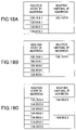
- FIGS. 11A through 11C are diagrams showing a payment ID storage table of the content server, a payment ID management table of the middleman server, and an ISP billing particulars table of the middleman server of the fifth method, respectively;
- FIGS. 12A through 12D are diagrams showing a billing address determination table of a bill collection server, a billing particulars table of the bill collection server, a payment ID determination table of an ISP router, and a band usage particulars table of the ISP router of the fifth method, respectively;
- FIG. 13A is a diagram showing a network structure of a first embodiment of the present invention.
- FIG. 13B is a diagram showing IP addresses of network components of the first embodiment
- FIGS. 14A through 14C are diagrams showing the user policy storage table, the middleman address management table, and the content information management table of the content server of the first embodiment, respectively;
- FIGS. 15A through 15C are diagrams showing the contractor ISP management table, the ISP policy table, and the policy reservation determination management table of the middleman server of the first embodiment, respectively;
- FIGS. 16A through 16C are diagrams showing the output side port band management tables of the policy servers of the first embodiment
- FIGS. 17A through 17C are diagrams showing the executed policy management tables of the policy servers of the first embodiment
- FIGS. 18A through 18C are diagrams showing the router management tables of the policy servers of the first embodiment
- FIGS. 19 and 20 are diagrams showing a sequence of steps of a system operation according to the first embodiment
- FIG. 21 is a flowchart of an operation of a user terminal according to the first embodiment
- FIG. 22 is a flowchart of an operation of the content server according to the first embodiment
- FIG. 23 is a flowchart of an operation of the middleman server according to the first embodiment
- FIG. 24 is a flowchart of an operation of each policy server according to the first embodiment
- FIG. 25 is a flowchart of another operation of each policy server according to the first embodiment.
- FIG. 26 is a flowchart of an operation of each ISP router according to the first embodiment
- FIGS. 27A through 27F are diagrams for illustrating steps S 1 and S 2 of the system operation of FIG. 19 ;
- FIGS. 28A through 28D are diagrams for illustrating steps S 3 through S 5 of the system operation of FIG. 19 ;
- FIGS. 29A through 29C are diagrams for illustrating step S 6 of the system operation of FIG. 19 ;
- FIGS. 30A and 30B are diagrams for illustrating step S 7 of the system operation of FIG. 19 ;
- FIGS. 31A through 31E are diagrams for illustrating step S 7 of the system operation of FIG. 19 ;
- FIGS. 32A through 32C are diagrams for illustrating step S 8 of the system operation of FIG. 19 ;
- FIGS. 33A through 33E are diagrams for illustrating steps S 9 and S 10 of the system operation of FIGS. 19 and 20 ;
- FIGS. 34A through 34E are diagrams for illustrating steps S 11 through S 13 of the system operation of FIG. 20 ;
- FIGS. 35A through 35C are diagrams for illustrating steps S 14 and S 15 of the system operation of FIG. 20 ;
- FIG. 36 is a diagram showing a sequence of steps of a system operation according to a second embodiment of the present invention.
- FIG. 37 is a flowchart of an operation of the user terminal according to the second embodiment.
- FIG. 38 is a flowchart of an operation of the content server according to the second embodiment.
- FIG. 39 is a flowchart of an operation of the middleman server according to the second embodiment.
- FIG. 40 is a flowchart of an operation of the client management server according to the second embodiment.
- FIGS. 41A through 41C are diagrams showing the client management tables according to the second embodiment.
- FIGS. 42A through 42D are diagrams for illustrating steps S 21 and S 22 of the system operation of FIG. 36 ;
- FIGS. 43A through 43D are diagrams for illustrating steps S 23 through S 25 of the system operation of FIG. 36 ;
- FIGS. 44A through 44D are diagrams for illustrating step S 26 of the system operation of FIG. 36 ;
- FIGS. 45A through 45E are diagrams for illustrating step S 27 of the system operation of FIG. 36 ;
- FIGS. 46A through 46D are diagrams for illustrating steps S 28 and S 29 of the system operation of FIG. 36 ;
- FIG. 47 is a diagram showing a sequence of steps of a system operation according to a third embodiment of the present invention.
- FIG. 48 is a flowchart of an operation of the content server according to the third embodiment.
- FIG. 49 is a flowchart of an operation of the middleman server according to the third embodiment.
- FIG. 50 is a flowchart of an operation of the copy server according to the third embodiment.
- FIGS. 51A and 51B are diagrams showing the copy content management table of the content server and the user policy storage table of the copy server according to the third embodiment, respectively;
- FIG. 52 is a diagram for illustrating step S 31 of the system operation of FIG. 47 ;
- FIGS. 53A through 53F are diagrams for illustrating step S 32 of the system operation of FIG. 47 ;
- FIGS. 54A through 54E are diagrams for illustrating steps S 33 through S 38 of the system operation of FIG. 47 ;
- FIG. 57 is a flowchart of an operation of the user terminal according to the fourth embodiment.
- FIG. 59 is a flowchart of an operation of the middleman server according to the fourth embodiment.
- FIG. 60 is a flowchart of an operation of each policy server according to the fourth embodiment.
- FIG. 61 is a flowchart of an operation of each router according to the fourth embodiment.
- FIGS. 62A through 62C are diagram showing the output side port band management tables of the policy servers according to the fourth embodiment.
- FIGS. 63A through 63C are diagrams showing the executed policy management tables of the policy servers according to the fourth embodiment.
- FIGS. 65A through 65D are diagrams for illustrating step S 43 of the system operation of FIG. 55 ;
- FIGS. 66A through 66C are diagrams for illustrating steps S 44 and S 45 of the system operation of FIG. 55 ;
- FIGS. 67A through 67E are diagrams for illustrating step S 46 of the system operation of FIG. 55 ;
- FIGS. 68A through 68E are diagrams for illustrating steps S 47 and S 48 of the system operation of FIGS. 55 and 56 ;
- FIGS. 69A and 69B are diagrams for illustrating step S 49 of the system operation of FIG. 56 ;
- FIG. 70B is a diagram showing IP addresses of network components of the fifth embodiment.
- FIG. 73 is a flowchart of an operation of the user terminal according to the fifth embodiment.
- FIG. 74 is a flowchart of an operation of the content server according to the fifth embodiment.
- FIG. 75 is a flowchart of an operation of each content server according to the fifth embodiment.
- FIG. 77 is a flowchart of an operation of each bill collection server according to the fifth embodiment.
- FIGS. 78 and 79 are flowcharts of an operation of each ISP router according to the fifth embodiment.
- FIGS. 80A and 80B are diagrams showing the payment ID storage tables of the content servers according to the fifth embodiment.
- FIG. 83A is a diagram showing the payment ID determination table of each ISP router according to the fifth embodiment.
- FIGS. 83B through 83E are diagrams showing the band usage particulars tables of the ISP routers according to the fifth embodiment.
- FIGS. 86A and 86B are diagrams for illustrating step S 54 of the system operation of FIG. 71 ;
- FIG. 87 is a diagram for illustrating step S 55 of the system operation of FIG. 71 ;
- FIGS. 88A through 88C are diagrams for illustrating step S 56 of the system operation of FIG. 71 ;
- FIGS. 89A through 89C are diagrams for illustrating steps S 57 through S 59 of the system operation of FIG. 71 ;
- FIGS. 90A through 90C are diagrams for illustrating step S 60 of the system operation of FIG. 71 ;
- FIGS. 91A through 91C are diagrams for illustrating steps S 61 and S 62 of the system operation of FIG. 71 ;
- FIGS. 92A through 92D are diagrams for illustrating steps S 63 and S 64 of the system operation of FIG. 71 ;
- FIGS. 94A through 94E are diagrams for illustrating steps S 68 and S 69 of the system operation of FIG. 72 ;
- a transmission band frequency band
- a server of the middleman (intermediary server) (hereinafter referred to as a middleman server ⁇ ) commands the reservation of a transmission band (a band reservation) for devices such as routers on the transmission line between the two parties based on a policy (a desired band value to be reserved, a reservation start date and time, etc.) of a user terminal (hereinafter referred to as a DTE-a) between the DTE-a and a server of the content (service) provider (hereinafter referred to as a content server ⁇ ).
- a policy a desired band value to be reserved, a reservation start date and time, etc.
- FIG. 1 is a diagram showing a system configuration of the first method.
- the system of FIG. 1 includes the DTE-a, ISPs (ISP-a and ISP-b), the content server ⁇ , and the middleman server ⁇ .
- the content server ⁇ includes a line connection part 11 , a control part 12 , and contents 16 .
- the line connection part 11 provides an interface with a network such as the Internet, and inputs and outputs data.
- the line connection part 11 receives data and transfers the data to the control part 12 for processing.
- the line connection part 11 also outputs data that the control part 12 requests to be transmitted.
- the control part 12 includes a middleman address data management table 13 , a content information management table 14 , and a user policy storage table 15 , and processes the data received from the line connection part 11 in accordance with the tables 13 through 15 . Further, the control part 12 can perform an IP trace route (an IP route tracing) and process an Internet control message protocol (ICMP) message responding to the IP trace route.
- IP trace route an IP route tracing
- ICMP Internet control message protocol
- FIG. 2A is a diagram showing an example of the middleman address management table 13 .
- the middleman address management table 13 prestores the IP address of the middleman server ⁇ .
- the middleman address management table 13 is used for setting the IP address of the middleman server ⁇ in the user policy storage table 15 when a message requesting a band reservation (a band reservation request) arrives from the user.
- FIG. 2B is a diagram showing an example of the content information management table 14 .
- the content information management table 14 prestores a content capacity for each of the contents 16 .
- the content information management table 14 is used for calculating a content transmission reservation end time in setting a content transmission reservation date and time in the user policy storage table 15 when the band reservation request arrives from the user.
- FIG. 2C is a diagram showing an example of the user policy storage table 15 .
- the user policy storage table 15 stores, for each of a series of ordering numbers (unique numbers in the content server ⁇ ), such information as middleman IP address, IP address of a user requesting a band reservation, content name, desired band value to be reserved (requested band), reservation start date and time, reservation end date and time, and router port IP addresses.
- ordering numbers unique numbers in the content server ⁇
- control part 12 calculates the content transmission end time from the capacity of the content extracted from the content information management table 14 and the requested band transmitted together with the content name, and sets the calculated content transmission end time in the column of reservation end date and time.
- control part 12 performs the IP trace route on the basis of the IP address of the user, and enters the IP addresses of all the ports of routers (for instance, ISP routers 40 - a and 40 - b in FIG. 1 ) on a transmission line obtained from the ICMP message responding to the trace route in the column of router port IP address.
- the obtained IP addresses are used later as information for identifying the routers for reserving the band between the DTE-a and the content server ⁇ .
- the operation is performed in the following steps.
- the control part 12 assigns an ordering number to the request and sets the middleman IP address, the user IP address, the content name, the requested band, the reservation start date and time, the reservation end date and time, and the IP addresses of all the router ports between the DTE-a and the content server ⁇ in the user policy storage table 15 .
- the control part 12 Letting the middleman IP address set in the user policy storage table 15 be a destination address, the control part 12 transmits the contents of the columns (of the user policy storage table 15 ) corresponding to the ordering number except for the content name to the middleman server ⁇ as the band reservation request from the user.
- the contents transmitted here may be referred to as a “policy” of the user.
- step (c) Receiving the band reservation result assigned the ordering number from the middleman server ⁇ , the content server ⁇ searches the user policy storage table 15 based on the ordering number, and transmits the band reservation result having the ordering number, letting the user IP address corresponding to the ordering number be a destination address. Since the band reservation contents recorded in their respective columns in a row of the user policy storage table 15 which row corresponds to the ordering number are based on the request from the user, as is apparent from step (a), the band reservation result is accurately transmitted to the DTE-a.
- the ordering number transmitted to the DTE-a is used to release the reserved band in the middle of communication, which is later described in the part of a fourth method.
- the middleman server ⁇ includes a line connection part 21 , a control part 22 , a contractor ISP management table 23 , an ISP policy table 24 , and a policy reservation determination management table 25 .
- the line connection part 21 provides an interface with a network such as the Internet, and inputs and outputs data.
- the line connection part 21 receives data and transmits the received data to the control part 22 for processing.
- the line connection part 21 also outputs data that the control part 22 requests to be transmitted.
- the control part 22 includes the contractor ISP management table 23 , the ISP policy table 24 , and the policy reservation determination management table 25 , and processes the data received from the line connection part 21 in accordance with the tables 23 through 25 .
- FIG. 3A is a diagram showing an example of the contractor ISP management table 23 .
- the contractor ISP management table 23 is used for searching for the IP addresses of the policy servers (band reservation setting servers) (for instance, policy servers 30 - a and 30 - b in FIG. 1 ) of the ISPs which policy servers can issue instructions to reserve the requested band (band reservation instructions) to the routers between the DTE-a and the content server ⁇ .
- the contractor ISP management table 23 prestores the IP addresses of the policy server and a client management server (employed in a later-described second method) for each of network addresses assigned to the ISPs managing the routers between the DTE-a and the content server ⁇ .
- the middleman server ⁇ receives the user policy from the content server ⁇ , extracts the IP addresses of the router ports based on the contents of the received policy. Using the network addresses determined from the router port IP addresses as keys, the middleman server ⁇ searches the contractor ISP management table 23 for the IP addresses of the policy servers or client management servers that can issue the instructions to the routers.
- FIG. 3B is a diagram showing an example of the ISP policy table 24 .
- the ISP policy table 24 temporarily stores the user policy received from the content server ⁇ .
- the ISP policy table 24 stores, for each of the policy servers of the ISPs that can issue the band reservation instructions to the routers between the DTE-a and the content server ⁇ , such information as order reception number (unique number in the middleman server ⁇ ), policy server IP address, user IP address, content server IP address, requested band, reservation start date and time, reservation end date and time, and router port IP address.
- the middleman server ⁇ assigns an order reception number to the IP address of each of the policy servers determined from the contractor ISP management table 23 , and sets the contents of the user policy (user IP address, requested band, reservation start date and time, and reservation end date and time) in their respective columns on the ISP policy table 24 .
- the policy servers are assigned serial order reception numbers, and the user policy is recorded for each of the serial order reception numbers.
- the middleman server ⁇ transmits a message requesting the band reservation to each of the policy servers, the contents of the columns (the user policy) except for the policy server IP address are transmitted with the policy server IP address being a destination address.
- FIG. 3C is a diagram showing an example of the policy reservation determination management table 25 .
- the policy reservation determination management table 25 is used for managing the result of the band reservation requested of each of the policy servers by the middleman server ⁇ . It is only when all the results of the band reservations requested of the policy servers between the DTE-a, and the content server ⁇ are OK that it is determined that the band is reserved all the way through between the DTE-a and the content server ⁇ . After the results of the band reservations are received from all the policy servers and recorded on the policy reservation determination management table 25 , the content server ⁇ is informed that the band reservation is OK (confirmed) if all the results are OK and that the band reservation is NG (not confirmed) if any of the results is NG.
- IP policy table 24 After the IP policy table 24 is created, with respect to each pair of the content server IP address and its ordering number, that is, with respect to each user policy requested by a content provider, a pair of the order reception number and the policy server IP address of each corresponding policy server is recorded on the policy reservation determination management table 25 .
- the operation is performed in the following steps.
- the control part 22 searches the contractor ISP address management table 23 for the IP addresses of the policy servers of the ISPs. Then, the control part 22 assigns the order reception number to each of the discovered policy server IP addresses and stores the user policy for each policy server in the ISP policy table 24 .
- control part 22 sets the IP address of the content provider (that is, the IP address of the content server ⁇ ), its ordering number, and the pairs of the policy server IP addresses and their order reception numbers corresponding to the IP address of the content provider and its ordering number in the policy reservation determination management table 25 .
- control part 22 transmits each pair of the order reception number and the user policy to the corresponding policy server with its policy server IP address obtained from the user policy stored in step (a) being a destination IP address.
- the control part 22 searches the policy reservation determination management table 25 and writes each reservation result to the corresponding column based on the transmitter IP address of each result message and its order reception number.
- step (e) Receiving the band reservation results from all the corresponding policy servers in step (d) and determining whether the band reservation requested by the user is confirmed or not, the control part 22 transmits the result of the band reservation for the user policy indicated by its ordering number to the content server ⁇ , letting the corresponding content server IP address recorded on the policy reservation determination management table 25 be a destination address.
- the ISPs include their respective policy servers 30 - a and 30 - b and ISP routers 40 - a and 40 - b .
- each of the policy servers 30 - a and 30 - b may be referred to equally as a policy server 30
- each of the ISP routers 40 - a and 40 - b may be referred to equally as an ISP router 40 or simply as a router 40 for convenience of description.
- the policy server 30 includes an output side port band management table 31 , an executed policy management table 32 , and a router management table 33 , which are shown as an output side port band management table 31 - a , an executed policy management table 32 - a , and a router management table 33 - a in FIG. 1 , respectively.
- FIG. 4A is a diagram showing an example of the output side port band management table 31 .
- the output side port band management table 31 manages a band control port and line bands left after band reservation (residual line band) classified by date and time with respect to each of the IP addresses of the routers 40 under the policy server 30 .
- the policy server 30 determines from the later-described router management table 33 the port number of the router 40 ( 40 - a in FIG. 1 ) for the band reservation requested by the user policy. Then, the policy server 30 determines that the band requested by the user policy is reservable if the requested band is smaller in data transmission amount than the residual line band of the port number throughout a given period of time of a desired reservation date and time. At this point, the policy server 30 decreases the data transmission amount (bps) of the residual line band by that of the requested band. At the same time, the policy server 30 informs the middleman server ⁇ that the requested band is reserved.
- FIG. 4B is a diagram showing an example of the executed policy management table 32 .
- the executed policy management table 32 is used for storing the user policy so that the policy server 30 can wait to instruct the router 40 to reserve or release the band until a specified execution time.
- the executed policy management table 32 stores, with respect to each policy number (a unique number in the policy server 30 ), IP address of an instructed router (destination IP address), transmitter IP address (content provider (server) IP address), requested band, reservation start date and time, reservation end date and time, middleman IP address, order reception number, router virtual IP address, and router output port number.
- the policy server 30 determines, with reference to the requested band of the user policy with its order reception number received from the middleman server ⁇ and the residual line band of the corresponding router port in the output side port band management table 31 , that the requested band of the user policy is reservable, the policy server 30 records the contents of the user policy in their respective columns with the corresponding policy number. At this time, the policy server 30 also records the discovered router output port number in the corresponding column.
- the policy server 30 transmits the user policy with its policy number to the router 40 and instructs the router 40 in accordance with the user policy.
- FIG. 4C is a diagram showing an example of the router management table 33 .
- the router management table 33 prestores relationships between the IP addresses assigned to the ports of the router 40 and the virtual IP address for controlling the router 40 .
- searching the router management table 33 by using as a key the router port IP address transmitted from the middleman server ⁇ together with the user policy having its order reception number, the number of the port actually used for the band reservation can be inquired, and a destination to which the instruction for the band reservation is given, or the virtual IP address of the router 40 , can be extracted.
- the policy server 30 searches the router management table 33 for the virtual IP address of the router 40 using the router port IP address included in the transmitted user policy.
- the policy server 30 transmits the user IP address included in the received user policy to the router 40 , letting the searched-out virtual IP address of the router 40 be a destination IP address, and transmits a message asking the output port of the router 40 at the time of performing the routing based on the user IP address.
- the policy server 30 receives the output port number from the router 40 , the policy server 30 refers to the output side port band management table 31 and confirms that the requested band of the user policy is smaller in data transmission amount than the residual line band of the output port number.
- the policy server 30 Determining that the requested band of the user policy is reservable in the residual line band of the output port of the router 40 , the policy server 30 enters the user policy in the executed policy management table 32 . At this time, the policy server 30 also enters the virtual IP address and the output port of the router 40 in the executed policy management table 32 . Further, the policy server 30 informs the middleman server ⁇ that the requested band of the user policy of the corresponding ordering number is reservable.
- the policy server 30 constantly monitors the executed policy management table 32 to instruct the router 40 to reserve or release the band at each specified execution time.
- the ISP router 40 Receiving the data (message) asking the number of its output port to the user from the policy server 30 , the ISP router 40 starts to find from which port data is output to the user IP address based on routing information and transmits the finding result to the policy server 30 .
- the ISP router 40 reserves or releases the line band of the port indicated by the data and transmits a message that the band reservation or release is completed to the policy server 30 .
- a middleman is allowed to reserve a certain transmission band (frequency band) on a transmission line between two parties (for instance, between a user and a content provider) in the case of transferring data between the two parties via a plurality of ISPs on the Internet.
- a certain transmission band frequency band
- the middleman server ⁇ commands the reservation of a transmission band (a band reservation) for the devices on the transmission line between the DTE-a and the content server ⁇ in the case of using the band of a connection line connecting the DTE-a to the ISP (ISP-a in FIG. 5 ) on a pay phone network as a band value to be reserved (a requested band) without the DTE-a setting the requested band.
- FIG. 5 is a diagram showing a system configuration of the second method.
- the system of FIG. 5 includes the DTE-a, the ISPs (ISP-a and ISP-b), the content server ⁇ , and the middleman server ⁇ .
- the content server ⁇ includes the line connection part 11 , the control part 12 , and the contents 16 .
- the control part 12 includes the middleman address management table 13 , the content information management table 14 , and the user policy storage table 15 .
- the line connection part 11 , the control part 12 , and the middleman address management table 13 are equal to those of the content server ⁇ of the first method.
- the content information management table 14 of the second method prestores a content capacity for each of the contents 16 .
- the content information management table 14 is searched for a content capacity for a requested content by using as a key the name of the content included in the message so that the middleman server ⁇ is informed of the content capacity.
- the content information management table 14 is used for figuring out a band reservation end date and time in the middleman server ⁇ based on the band to be reserved for the user, which band is to be determined in the middleman server ⁇ , and the content capacity and a band reservation start date and time transmitted from the content server ⁇ .
- the user policy storage table 15 of the second method is equal to that of the content server ⁇ of the first method. However, since the desired band value to be reserved is not transmitted from the user, the columns of requested band and reservation end date and time of the user policy storage table 15 remain blank with respect to the ordering number of the content server ⁇ .
- the operation is performed in the following steps.
- the control part 12 assigns an ordering number to the request, and sets the middleman IP address, the user IP address, the content name, the reservation start date and time, the IP addresses of all the routers between the DTE-a and the content server ⁇ in the user policy storage table 15 in the same manner as described in the first method.
- the control part 12 transmits the contents of the columns of the user policy storage table 15 except for the content name to the middleman server ⁇ as the band reservation request from the user, letting the middleman IP address set in the user policy storage table 15 be a destination address. However, the requested band value is not transmitted to the middleman server ⁇ because the column therefor remains blank.
- the content server ⁇ searches the user policy storage table 15 , based on the ordering number, for the user IP address corresponding to the ordering number, and transmits the band reservation result, letting the user IP address be a destination address. Since the contents of the band reservation corresponding to the ordering number are transmitted from the DTE-a, as is apparent from step (a), the result is accurately transmitted to the DTE-a.
- the middleman server ⁇ includes the line connection part 21 and the control part 22 .
- the control part 22 includes the contractor ISP management table 23 , the ISP policy table 24 , and the policy reservation determination management table 25 .
- the line connection part 21 , the control part 22 , and the policy reservation determination management part 25 are equal to those of the middleman server ⁇ of the first method.
- the contractor ISP management table 23 of the second method is used for searching for the IP addresses of the policy servers of the ISPs which policy servers can issue band reservation instructions to the routers between the DTE-a and the content server ⁇ .
- the contractor ISP management table 23 prestores the IP addresses of the policy server and the client management server (for instance, a client management server 50 in FIG. 5 ) for each of the network addresses assigned to the ISPs managing the routers between the DTE-a and the content server ⁇ .
- the middleman server ⁇ receives the user policy from the content server ⁇ , extracts the IP addresses of the routers based on the contents of the received policy. Based on the network addresses determined from the IP addresses, the middleman server ⁇ searches the contractor ISP management table 23 for the IP addresses of the policy servers that can issue the instructions to the routers. Further, upon receiving the user policy from the content server ⁇ , the middleman server ⁇ extracts the user IP address from the user policy.
- the middleman server ⁇ can obtain the IP address of the client management server storing the value of the line band used for the connection of the DTE-a to the ISP.
- the ISP policy table 24 of the second method temporarily stores policies transmitted from content providers.
- the ISP policy table 24 manages the policies for the ISPs by a series of order reception numbers (unique numbers in the middleman server ⁇ ) and is recorded with such information as policy server IP address, user IP address, requested band, reservation start date and time, and reservation end date and time for each of the order reception numbers.
- the control part 22 Upon receiving the user policy (content name, reservation start date and time, and router port IP addresses) and the content capacity from the content server ⁇ with the ordering number, the control part 22 extracts the corresponding policy server IP addresses from the ISP policy table 24 based on the router port IP addresses and the network addresses recorded on the contractor ISP management table 23 . The control part 22 assigns an order reception number to each of the policy server IP addresses and stores the contents of the user policy (the user IP address and the reservation start date and time) in their respective columns on the ISP policy table 24 .
- control part 22 inquires of the client management server of the ISP (ISP-a) “the band used for the connection of the DTE-a to the ISP” based on the corresponding network address of the user IP address.
- the control part 22 receives the result of the inquiry, the control part 22 figures out a content transmission end date and time from the value of the band used for the connection and the content capacity, and sets the value of the band used for the connection and the content transmission end date and time in the columns of requested band and reservation end date and time, respectively.
- the middleman server ⁇ When the middleman server ⁇ transmits the user policy for the band reservation to each of the corresponding policy servers of the ISPs, the middleman server ⁇ extracts the user policy from the ISP policy table 24 based on the corresponding pair of the order reception number and policy server IP address.
- the operation is performed in the following steps.
- the control part 22 searches the contractor ISP management table 23 , based on the network address of the ISP (ISP-a) determined from the user IP address included in the user policy, for the IP address of the client management server of the ISP (ISP-a) for managing the user.
- the control part 22 inquires about the connection line band value of the user, letting the searched-out IP address be a destination address.
- the control part 22 calculates a reservation end date and time from the connection line band value of the user transmitted from the client management server, and the content capacity and the reservation start date and time included in the user policy.
- the control part 22 searches the contractor ISP management table 23 for the IP addresses of the policy servers of the ISPs based on the network addresses of the ISPs determined from the IP addresses of the router port IP addresses included in the user policy.
- the control part 22 assigns the order reception number to each of the IP addresses of the policy servers and stores the user policy for each of the policy servers in the ISP policy table 24 .
- control part 22 sets the IP address and the ordering number of the content provider, or the content server ⁇ , and pairs of the IP addresses of the policy servers corresponding to the ordering number and their respective order reception numbers assigned thereto in step (d) in the policy reservation determination management part 25 .
- the control part 22 extracts the IP address of each policy server from the corresponding user policy stored in step (d), and transmits each pair of the order reception number and the user policy, letting the IP address of each policy server be a destination IP address.
- the control part 22 searches the policy reservation determination management table 25 and writes the band reservation results to the corresponding column on the policy reservation determination management table 25 based on the transmitter IP addresses of the messages and the transmitted order reception numbers.
- the middleman server ⁇ performs the same operation as step (e) of the operation of the middleman server ⁇ of the first method.
- the ISPs include their respective policy servers 30 , the ISP routers 40 , and client management servers 50 .
- Each client management server 50 includes a client management table 51 .
- each policy server 30 includes the output side port band management table 31 , the executed policy management table 32 , and the router management table 33 .
- the client management server 50 and the client management table 51 of the ISP-b are not shown in FIG. 5 for simplicity purposes.
- the policy server 30 and the ISP router 40 of the second method are equal to those of the first method.
- the client management server 50 includes the client management table 51 shown in FIG. 6 .
- the user IP address and the band used for the connection are set in the client management table 51 .
- the client management server 50 If the middleman server ⁇ inquires of the client management server 50 the band used for the connection when the connection of the user to the ISP is completed, the client management server 50 transmits the band used for the connection to the middleman server ⁇ by using the user IP address as a key.
- the client management server 50 performs an operation in the following steps.
- the client management server 50 receives from the middleman server ⁇ an inquiry about the band used for the connection of the user to the ISP at the time of the completion of the connection, the client management server 50 extracts the band used for the connection of the user from the client management table 51 , using the user IP address as a key.
- the client management server 50 transmits the extracted used band of the user to the middleman server ⁇ .
- a middleman is allowed to reserve a certain transmission band (frequency band) on a transmission line between two parties (for instance, between a user and a content provider) in the case of transferring data between the two parties via a plurality of ISPs on the Internet.
- a certain transmission band frequency band
- the middleman server ⁇ commands the reservation of a transmission band (a band reservation) for the devices on the transmission line between the DTE-a and the content provider (content server ⁇ ) when servers each having a copy of the content requested by the DTE-a (hereinafter referred to as copy servers) exist, apart from the content server ⁇ , in some places between the DTE-a and the content provider (content server ⁇ ) on the Internet and the content is distributed to the DTE-a from the copy server nearest the DTE-a.
- copy servers servers each having a copy of the content requested by the DTE-a
- FIG. 7 is a diagram showing a system configuration of the third method.
- the system of FIG. 7 includes the DTE-a, the ISPs (ISP-a and ISP-b), the content server ⁇ , and the middleman server ⁇ .
- the content server ⁇ includes the line connection part 11 , the control part 12 , and the contents 16 .
- the control part 12 includes the middleman address management table 13 , the content information management table 14 , the user policy storage table 15 , and a copy content management table 17 .
- the line connection part 11 , the middleman address management table 13 , and the content information management table 14 are equal to those of the content server ⁇ of the first method.
- the control part 12 includes the middleman address management table 13 , the content information management table 14 , the user policy management table 15 , and the copy content management table 17 , and processes data received from the line connection part 11 in accordance with the tables 13 through 15 and 17 . Further, the control part 12 performs an IP trace route and processes an ICMP message responding thereto.
- the user policy storage table is equal to that of the content server ⁇ of the first method. However, the trace route is performed from a copy server 60 . Therefore, in the user policy storage table 15 , the column of router port IP address remains blank with respect to the ordering number of the content server ⁇ .
- FIG. 8A is a diagram showing an example of the copy content management table 17 .
- the copy content management table 17 prestores the network address of the ISP (ISP-a in FIG. 7 ) that is under contract with the content provider to distribute a copy of the content and the IP address of the copy server 60 to which the copy content is to be distributed.
- the user policy (user IP address, content name, requested band, reservation start date and time, and reservation end date and time) stored in the user policy storage table 15 is transmitted to the copy server 60 to reserve a band from the copy server 60 to the user and distribute the copy content to the user.
- the copy content management table 17 is used for extracting the IP address of the copy server 60 therefrom based on the corresponding network address with the user IP address stored in the user policy storage table 15 being used as a key.
- the operation is performed in the following steps.
- the control part 12 assigns an ordering number to the request, and in the same manner as described in the first method, sets such information as middleman IP address, content name, requested band, reservation start date and time, and reservation end date and time in the user policy storage table 15 .
- the control part 12 transmits the contents of the columns of the user policy storage table 15 to the copy server 60 as the band reservation request from the user, letting the IP address of the copy server 60 be a destination address.
- the IP address of the copy server 60 is extracted from the copy content management table 17 based on the corresponding network address by using as a key the user IP address set in the user policy storage table 15 .
- the router port IP addresses which are obtained as a result of the trace route performed by the copy server 60 , are not transmitted.
- the content server ⁇ searches the user policy storage table 15 , based on the ordering number, for the user IP address corresponding to the ordering number, and transmits the result of the band reservation, letting the user IP address be a destination address. Since the contents of the band reservation corresponding to the ordering number are transmitted from the DTE-a, as is apparent from step (a), the result is accurately transmitted to the DTE-a.
- the middleman server ⁇ includes the line connection part 21 and the control part 22 .
- the control part 22 includes the contractor ISP management table 23 , the ISP policy table 24 , and the policy reservation determination management table 25 .
- the line connection part 21 , the control part 22 , and the policy reservation determination management part 25 are equal to those of the middleman server ⁇ of the first method.
- the contractor ISP management table 23 is used for searching for the IP address of the policy server (the policy server 30 in FIG. 7 ) of the ISP (ISP-a in FIG. 7 ) which policy server can issue a band reservation instruction to a router (the ISP router 40 in FIG. 7 ) between the DTE-a and the copy server 60 .
- the contractor ISP management table 23 prestores the IP address of the policy server for each of the network addresses assigned to the ISPs managing routers between the DTE-a and copy servers.
- the middleman server ⁇ extracts the IP address of the router based on the contents of the received policy. Using the network address determined from the IP address as a key, the middleman server ⁇ searches the contractor ISP management table 23 and obtains the IP address of the policy server that can issue the instruction to the router.
- the ISP policy table 24 temporarily stores user policies transmitted from the copy servers.
- the user policies for the ISPs and the IP addresses of the policy servers that can issue the band reservation instructions are stored in accordance with a series of order reception numbers.
- the middleman server ⁇ After receiving the user policy with the ordering number from the copy server 60 , the middleman server ⁇ operates in the same way as that of the first method.
- the control part 22 searches the contractor ISP management table 23 , based on the network address of the ISP (ISP-a) determined from the router port IP address included in the user policy, for the IP address of the policy server (the policy server 30 - a ) of the ISP (ISP-a) for managing the user.
- the control part 22 assigns the order reception number to the searched-out IP address of the policy server, and sets the user policy for the policy server in the ISP policy table 24 .
- the middleman server ⁇ operates in the same way as that of the first method.
- the ISPs include their respective policy servers 30 , ISP routers 40 , and copy servers 60 .
- Each policy server 30 includes the output side port band management table 31 , the executed policy management table 32 , and the router management table 33 .
- Each copy server 60 includes a user policy storage table 61 .
- the copy server 60 and the user policy storage table 61 of the ISP-b are not shown in FIG. 7 for simplicity purposes.
- the output side port band management table 31 , the executed policy management table 32 , and the router management table 33 of the policy server 30 are equal to those of the policy server 30 of the first method.
- the ISP router 40 operates in the same way as that of the first method.
- the copy server 60 includes the user policy storage table 61 and processes data received from the content server ⁇ .
- the copy server 60 can perform an IP trace route and process an ICMP message responding thereto.
- FIG. 8 is a diagram showing an example of the user policy storage table 61 .
- the user policy storage table 61 is used in the same way as the user policy storage table 15 of the first method.
- the user policy storage table 61 is used so that the copy server 60 replaces the content server ⁇ to make a band reservation request accompanying the user policy to the middleman server ⁇ .
- the contents of the request are recorded on the user policy storage table 61 .
- the trace route is performed based on the user IP address and the IP addresses of all router ports (in the case of FIG. 7 , a port of the router 40 - a ) on the transmission line are obtained from the ICMP message, the IP addresses are recorded in the column of router port IP address.
- the band reservation request is made to the middleman server ⁇ in accordance with the contents set in the user policy storage table 61 .
- the operation is performed in the following steps.
- the control part (not shown in the drawing) of the copy server 60 sets the contents in the corresponding columns on the user policy storage table 61 in the same way as the contents of the user policy are stored in the user policy storage table 15 of the first method.
- the copy server 60 operates in the same way as the content server ⁇ of the first method.
- a middleman is allowed to reserve a certain transmission band (frequency band) on a transmission line between two parties (for instance, between a user and a content provider) in the case of transferring data between the two parties via a plurality of ISPs on the Internet.
- a certain transmission band frequency band
- the middleman server ⁇ releases a reserved band at the request of the DTE-a to release the reserved band (a reserved band release request) while a content is downloaded at a band value requested by the DTE-a between the DTE-a and the content server ⁇ .
- FIG. 9 is a diagram showing a system configuration of the fourth method.
- the system of FIG. 9 includes the DTE-a, the ISPs (ISP-a and ISP-b), the content server ⁇ , and the middleman server ⁇ .
- Each of the ISP-a and ISP-b includes a plurality of routers (indicated by 40 - a 1 and 40 - a 2 for the ISP-a; only the router 40 - b is shown for the ISP-b for simplicity purposes).
- the routers are equally referred to by the numeral 40 for convenience of description.
- the content server ⁇ includes the line connection part 11 , the control part 12 , and the contents 16 .
- the control part 12 includes the middleman address management table 13 , the content information management table 14 , and the user policy storage table 15 .
- the line connection part 11 , the control part 12 , the middleman address management table 13 , the content information management table 14 , and the user policy storage table 15 are equal to those of the content server ⁇ of the first method.
- the operation is performed in the following steps.
- the control part 12 searches the user policy storage table 15 for the IP address of the middleman based on the ordering number, and transmits the band reservation release request with the ordering number to the middleman server ⁇ with the searched-out IP address of the middleman being a destination address.
- the control part 12 receives the ordering number of the user policy to be deleted from the middleman server ⁇ , and deletes the user policy corresponding to the ordering number.
- the middleman server ⁇ includes the line connection part 21 and the control part 22 .
- the control part 22 includes the contractor ISP management table 23 , the ISP policy table 24 , and the policy reservation determination management table 25 .
- the line connection part 21 , the control part 22 , the contractor ISP management table 25 , the ISP policy table 24 , and the policy reservation determination management table 25 are equal to those of the middleman server ⁇ of the first method.
- the operation is performed in the following steps.
- the control part 22 searches the policy reservation determination table 25 for the order reception numbers and the policy server IP addresses corresponding to the ordering number.
- the control part 22 transmits messages with the order reception numbers requesting the release of the reserved band to the corresponding policy servers, letting the searched-out IP addresses of the policy servers be destination addresses.
- the control part 22 receives a message (data) confirming the release of the reserved band corresponding to the order reception number back from any of the policy servers, the control part 22 turns off the reservation flag of the order reception number in the policy reservation determination management table 25 .
- the reservation flags are turned on if the requested band is reserved.
- the control part 22 deletes all the data corresponding to the order reception numbers and transmits the message that the release is completed with respect to the ordering number to the content server ⁇ .
- the ISP-a and ISP-b includes their respective policy servers 30 and ISP routers 40 .
- the policy server 30 includes the output side port band management table 31 , the executed policy management table 32 , and the router management table 33 .
- the output side port band management table 31 , the executed policy management table 32 , and the router management table 33 are equal to those of the policy server 30 of the first method in configuration and operation.
- the policy server 30 operates in the following steps.
- the policy server 30 searches the executed policy management table 32 based on the transmitter IP address and the order reception number of the message. Letting the router IP address (an address to which band reservation and release instructions are given) corresponding to the transmitter IP address and the order reception number of the message be a destination address, the policy server 30 transmits to the corresponding router a message that the user policy corresponding to the transmitter IP address and the order reception number of the message is to be deleted.
- the policy server 30 increases the residual line band (data amount) of the corresponding router port in the output side port band management table 31 by the amount of the released band, using as a key the corresponding number of the output port of the router in the executed policy management table 32 .
- the policy server 30 transmits the message (data) confirming the deletion of the user policy having the order reception number to the middleman server ⁇ .
- the ISP router 40 operates in the same way as that of the first method.
- a fifth method of the present invention in the case of transferring data between two parties via a plurality of ISPs on the Internet, with a band reservation being made by an RSVP message assigned an ID (a payment ID) issued in advance by a middleman and with routers on a transmission line checking the ID included in the reservation message, the band reservation can be authorized with the ID guaranteeing the middleman a charge payment for the band reservation.
- an RSVP message assigned an ID (a payment ID) issued in advance by a middleman and with routers on a transmission line checking the ID included in the reservation message
- FIG. 10 is a diagram showing a system configuration of the fifth method.
- the system of FIG. 10 includes the DTE-a, the ISPs (ISP-a and ISP-b), the content server ⁇ , and the middleman server ⁇ .
- the content server ⁇ includes the line connection part 11 , the control part 12 , and the contents 16 .
- the line connection part is equal to that of the content server ⁇ of the first method.
- the control part 12 includes a payment ID storage table 18 , and processes data received from the line connection part 11 . Further, the control part 12 can perform and process operations in conformity to the RSVP protocol.
- FIG. 11A is a diagram showing an example of the payment ID storage table 18 .
- the payment ID storage table 18 is used for storing an ID (a payment ID) issued when the content provider and the middleman make a general contract for payment for band reservation.
- the ID is transmitted and received as an object of each RSVP message such as a Path message, a Resv message, a Resv Tear message, or a Path Tear message, and is used for a router to determine whether the message (RSVP message) requesting the band reservation is payment-guaranteed. Further, the ID is exchanged as a key used by router-managing servers or the middleman to confirm a guarantee on payment for the band reservation.
- the operation is performed in the following steps.
- the content server ⁇ (a) Receiving the content request from the DTE-a, first, the content server ⁇ starts to transmit a requested content to the DTE-a without reserving a band. Further, in order to cause the routers on the transmission line to the DTE-a to prepare for the band reservation, the content server ⁇ includes the ID extracted from the payment ID storage table 18 in the Path message as an object, and transmits the Path message, letting the IP address of the DTE-a be a destination address.
- the content server ⁇ controls a transfer rate for the transmitted content in accordance with a band to be reserved (the requested band) of flow spec objects in the Resv message.
- the content server ⁇ pays the middleman the amount billed and charges the user the amount paid.
- the middleman server ⁇ includes the line connection part 21 and the control part 22 .
- the line connection part 21 is equal to that of the middleman server ⁇ of the first method.
- the control part 22 includes a payment ID management table 26 and an ISP billing particulars table 27 , and processes data received from the line connection part 21 in accordance with the tables 26 and 27 .
- FIG. 11B is a diagram showing an example of the payment ID management table 26 .
- the payment ID management table 26 is recorded with payment IDs issued in advance to content providers (servers) for their respective IP addresses when the middleman contracts the content providers.
- the payment ID to the content server ⁇ is stored in the payment ID management table 26 , being correlated with the IP address of the content server ⁇ .
- FIG. 11C is a diagram showing an example of the ISP billing particulars table 27 .
- the ISP billing particulars table 27 is recorded with billing particulars transmitted from a server (a bill collection server 80 in FIG. 10 ) that manages a router (the router 40 - a in FIG. 10 ) and collects a bill for a band reservation.
- a server a bill collection server 80 in FIG. 10
- the router 40 - a in FIG. 10 collects a bill for a band reservation.
- the operation is performed in the following steps.
- the control part 22 (a) Receiving the billing particulars with the payment ID from the bill collection server 80 , which has received the usage particulars of the reserved band (band usage particulars) from the ISP router 40 - a , the control part 22 records the billing particulars on the ISP billing particulars table 27 .
- control part 22 After a given period of time passes, the control part 22 searches the ISP billing particulars table 27 for the IP address of the content server ⁇ corresponding to the payment ID, and transmits the billing particulars, letting the searched-out IP address be a destination address.
- the bill collection server 80 includes a billing address determination table 81 and a billing particulars table 82 .
- FIG. 12A is a diagram showing an example of the billing address determination table 81 .
- the billing address determination table 81 prestores a middleman IP address that is a billing address for a payment ID when a middleman contracts an ISP (the ISP-a in FIG. 10 ) that manages the bill collection server 80 and the ISP router 40 .
- FIG. 12B is a diagram showing an example of the billing particulars table 82 .
- the billing particular table 82 is recorded with the band usage particulars (payment ID, destination IP address, and destination port number) collected from the ISP router 40 .
- the bill collection server 80 collects the band usage particulars at regular intervals from the ISP router 40 managed and identified by the bill collection server 80 , letting the IP address of the ISP router 40 be a destination address.
- the bill collection server 80 extracts the IP address of the middleman server ⁇ that is the billing address from the billing address determination table 81 based on the payment ID included in the band usage particulars.
- the bill collection server 80 transmits the band usage particulars to the middleman server ⁇ with the extracted IP address being a destination address.
- the ISP router 40 is capable of interpreting an object of a newly defined payment ID in each RSVP message, and includes a payment ID determination table 41 and a band usage particulars table 42 .
- FIG. 12C is a diagram showing an example of the payment ID determination table 41 .
- the payment ID determination table 41 stores a payment ID when a middleman contracts an ISP managing the bill collection server 80 and the ISP router 40 .
- FIG. 12D is a diagram showing an example of the band usage particulars table 42 .
- the band usage particulars table 42 is recorded with such information as payment ID, destination IP address, destination port number, reserved (requested) band, use start date and time, and use end date and time.
- each RSVP message Path message, Resv message, Resv Tear message, and Path Tear message
- the ISP router 40 transmits the band usage particulars to the bill collection server 80 .
- the ISP router 40 (a) Receiving the Path message including the payment ID as an object from the content server ⁇ , the ISP router 40 confirms whether the payment ID matches that recorded on the payment ID determination table 41 (that is, whether the payment ID is recorded on the payment ID determination table 41 ). If it is confirmed in the affirmative, the ISP router 40 records session objects (destination IP address and destination port number) included in the Path message as well as the payment ID on the band usage particulars table 42 . Thereafter, the ISP router 40 transmits the Path message to the DTE-a.
- the ISP router 40 receives the Resv message including the payment ID as an object from the DTE-a, the ISP router 40 confirms whether the payment ID and the session objects match those recorded on the band usage particulars table 42 . If it is confirmed in the affirmative, the ISP router 40 sets the requested band set as a flow spec object in the Resv message actually as a band to be reserved by the ISP router 40 . At this time, the ISP router 40 records the requested band and a usage start date and time at which the requested band is reserved on the band usage particulars table 42 . Thereafter, the router 40 transmits the Resv message to the content provider (the content server ⁇ ).
- the content provider the content server ⁇
- the ISP router 40 receives the message notifying the collection of the stored band usage particulars from the bill collection server 80 managing the ISP router 40 , the ISP router 40 transmits the band usage particulars stored by that time to the bill collection server 80 .
- a content server in distributing its content to a user terminal (user) via the Internet, transmits to a middleman server (middleman) the IP addresses of the user terminal and the content server, a desired band value to be reserved (a requested band) on a transmission line between the user terminal and the content server, the IP addresses of the ports of all routers between the user terminal and the content server so that the middleman server causes policy servers between the user terminal and the content server to reserve the requested band.
- a middleman server middleman the IP addresses of the user terminal and the content server, a desired band value to be reserved (a requested band) on a transmission line between the user terminal and the content server, the IP addresses of the ports of all routers between the user terminal and the content server so that the middleman server causes policy servers between the user terminal and the content server to reserve the requested band.
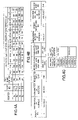
- FIG. 13A is a diagram showing a network structure of the first embodiment.
- FIG. 13A is a diagram showing a network structure of the first embodiment.
- second through fourth embodiments will also be given with reference to FIG. 13 A.
- a network of the first embodiment includes user terminals (DTE-a through DTE-c), ISPs (ISP-a through ISP-c), a server of a content provider ⁇ (a content server ⁇ ), and a server of a middleman ⁇ (a middleman server ⁇ ).
- the content server ⁇ and the middleman server ⁇ are equal in structure and operation to those previously described in the first through fifth method.
- the ISP-a includes a policy server Pa, a client management server Ka, a copy server Sa, and a router Ra.
- the ISP-b includes a policy server Pb, a client management server Kb, a copy server Sb, and a router Rb.
- the ISP-c includes a policy server Pc, a client management server Kc, a copy server Sc, and routers Rc and Rd.
- the policy servers Pa through Pc are equal to the above-described policy server 30
- the client management servers Ka through Kc are equal to the above-described client management server 50
- the copy servers Sa through Sc are equal to the above-described copy server 60
- the routers Ra through Rd are equal to the above-described routers 40 .
- the router Ra includes ports P 1 through P 4
- the router Rb includes ports PS through P 9
- the router Rc includes ports P 10 through P 13
- the router Rd includes ports P 14 through P 16 .
- the content server ⁇ includes the middleman address management table 13 , the content information management table 14 , and the user policy storage table 15 as shown in FIG. 1 .
- the middleman server ⁇ includes the contractor ISP management table 23 , the ISP policy table 24 , and the policy reservation determination management table 25 as shown in FIG. 1 .
- IP addresses of the above-described components of the network are shown in FIG. 13B .
- a variety of data is set in each of the following network components.
- a band of “128 Kbps” is reserved in advance on a transmission line between the DTE-b and DTE-c for a period of 10:00 to 12:00 on 2001/9/1.
- the content server ⁇ includes the middleman address management table 13 , the content information management table 14 , and the user policy storage table 15 .
- the user policy management table 15 manages a band reservation request from the user (DTE-a) by a serial ordering number assigned thereto.
- the band reservation request from the user is called a “policy”.
- the middleman address management table 13 manages the IP address of the middleman ⁇ (middleman server ⁇ ) so as to transmits the user policy to the middleman ⁇ .
- the middleman address management table 13 prestores the IP address of the middleman server ⁇ .
- the content information management table 14 manages a content capacity for calculating a reservation end time for the band request from the user.
- the content information management table 14 stores information on contents A and B.
- the middleman server ⁇ includes the contractor ISP management table 23 , the ISP policy table 24 , and the policy reservation determination management table 25 .
- the contractor ISP management table 23 manages the network addresses of the ISP-a through ISP-c and the IP addresses of the policy servers Pa through Pc and the client management servers Ka through Kc so as to make band reservation for the ISP-a through ISP-c.
- the contractor ISP management table 23 prestores the network addresses of the ISP-a through ISP-c and the IP addresses of the policy servers Pa through Pc and the client management servers Ka through Kc.
- the ISP policy table 24 temporarily stores the user policy (band reservation request from the user) transmitted from the content server ⁇ and manages the user policy by a serial order reception number assigned thereto so as to transmit the user policy to each of the policy servers Pa through Pc of the ISP-a through ISP-c.
- the policy reservation determination management table 25 manages band reservation results transmitted from the policy servers Pa through Pc.
- Each of the policy servers Pa through Pc of the ISP-a through ISP-c includes the output side port band management table 31 , the executed policy management table 32 , and the router management table 33 .
- FIGS. 16A through 16C are diagrams showing the output side port band management tables 31 of the policy servers Pa through Pc, respectively, according to this embodiment.
- each output side port band management table 31 manages the bands of the output ports of the corresponding router(s).
- the band of “128 Kbps” is reserved on the transmission line between the DTE-b and the DTE-c for a period of 10:00 to 12:00 on 2001/9/1.
- FIGS. 17A through 17C are diagrams showing the executed policy management tables 32 of the policy servers Pa through Pc, respectively, according to this embodiment.
- each executed policy management table 32 manages the user policy operated by the corresponding router(s) by a serial policy number assigned to the user policy.
- the band of “128 Kbps” is reserved on the transmission line between the DTE-b and the DTE-c for the period of 10:00 to 12:00 on 2001/9/1.
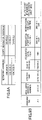
- FIGS. 18A through 18C are diagrams showing the router management tables 33 of the policy servers Pa through Pc, respectively, according to this embodiment.
- each router management table 33 manages IP addresses used for identifying the corresponding router(s) and its ports in transmitting to the corresponding router(s) the user policy transmitted from the middleman server ⁇ .
- Each of the routers Ra through Rd of the ISP-a through ISP-c has given routing information, and routing is performed based on the routing information.
- FIGS. 19 and 20 are diagrams showing a sequence of steps of a system operation according to the first embodiment.
- FIGS. 21 through 26 are flowcharts of operations of the DTE-a, the content server ⁇ , the middleman server ⁇ , the policy servers Pa through Pc, and the routers Ra through Rc.
- step S 1 of FIG. 19 the user selects conditions to be requested from the list of contents displayed on a web screen of the DTE-a, and the DTE-a transmits an IP packet including the conditions to the content server ⁇ .
- This operation corresponds to steps S 10101 through S 10102 of FIG. 21 .
- the IP packet transmitted to the content server ⁇ is shown in FIG. 27A .
- the conditions requested by the DTE-a are as follows:
- Desired band value to be reserved 64 Kbps
- the DTE-a waits for a band reservation result transmitted from the content server ⁇ (step S 10103 of FIG. 21 ).
- step S 2 of FIG. 19 when the content server ⁇ , which waits to receive data (step S 10201 of FIG. 22 ), receives the IP packet (step S 10202 ), the content server ⁇ identifies the transmitter of the IP packet (step S 10203 ) and extracts from the IP packet its transmitter IP address and the requested conditions (content name, requested band, and reservation start date and time) of the DTE-a (step S 10204 ).
- the content server ⁇ extracts the IP address of the middleman server ⁇ from the middleman address management table 13 (step S 10205 ).
- the content server ⁇ searches the content information management table 14 for the content name (content A) specified by the DTE-a, and calculates a reservation (transmission) end date and time from a content capacity for the content name (step S 10206 ).
- a reservation (transmission) end date and time is calculated at 2001/9/1, 12:00 p.m. as shown in FIG. 27 D( c ).
- the content server ⁇ assigns an ordering number “ ⁇ 1” to a group of the obtained data items (middleman server IP address, content name, transmitter IP address, requested band, reservation start date and time, and calculated reservation end date and time), and records the data in the respective columns (ordering number, middleman IP address, content name, user IP address, requested band, reservation start date and time, and reservation end date and time) on the user policy storage table 15 (step S 10207 ).
- the content server ⁇ in order to reserve a data transfer route for the content A on the transmission line between the DTE-a and the content server ⁇ , the content server ⁇ , letting the data recorded in the column of user IP address of the user policy storage table 15 be a destination address, transmits an IP trace route shown in FIG. 27E to the DTE-a (step S 10208 ).
- step S 3 of FIG. 19 when the router Rc, which waits to receive data (step S 10601 of FIG. 26 ), receives the IP trace route (step S 10602 ), the router Rc identifies the transmitter of the IP trace route (step S 10603 ) and transmits an ICMP message as shown in FIG. 28A to the content server ⁇ with the transmitter IP address of the IP trace route and the IP address of its port P 12 being set as the destination IP address and the transmitter IP address of the ICMP message, respectively (step S 10604 ).
- step S 4 of FIG. 19 receiving the ICMP message from the router Rc, the content server ⁇ extracts the transmitter IP address from the ICMP message and records the transmitter IP address in the column of router port IP address on the user policy storage table (step S 10209 of FIG. 22 ).
- step S 5 of FIG. 19 the router Rc transmits the IP trace route to the router Rb as in step S 2 , and the router Rb, receiving the IP trace route, transmits an ICMP message to the content server ⁇ . Thereafter, the router Ra operates in the same way as in steps S 2 and S 3 (steps S 10601 through S 10604 ).
- FIG. 28C is a diagram showing the ICMP message transmitted from the router Rb to the content server ⁇
- FIG. 28D is a diagram showing the ICMP message transmitted from the router Ra to the content server ⁇ .
- step S 6 of FIG. 19 receiving the ICMP messages from the routers Rb and Ra, the content server ⁇ extracts the transmitter IP addresses of the ICMP messages as in step S 4 , and records the extracted transmitter IP addresses in the column of router port IP address on the user policy storage table 15 .
- FIG. 29A is a diagram showing the user policy storage table 15 recorded further with the transmitter IP addresses of the routers Rb and Ra. Thereafter, it is determined whether the content server ⁇ has received the ICMP messages from all the routers (the routers Ra through Rc in this case) on the transmission line between the DTE-a and the content server ⁇ (step S 10210 of FIG. 22 ).
- step S 10210 If it is determined in the negative in step S 10210 , the steps S 10201 through S 10203 and S 10209 are repeated until the content server ⁇ receives the ICMP messages from all the routers Ra through Rc.
- step S 10211 the content server ⁇ , letting the data corresponding to the ordering number ⁇ 1 in the column of middleman server IP address of the user policy storage table 15 be a destination IP address, transmits to the middleman server ⁇ an IP packet including the items of the user policy (ordering number, user IP address, requested band, reservation start date and time, reservation end date and time, and router port IP addresses (input side)) of the ordering number ⁇ 1.
- the IP packet includes information indicated by hatching in FIG. 29B as data.
- FIG. 29C is a diagram showing the IP packet.
- step S 7 of FIG. 19 when the middleman server ⁇ , which waits to receive data (step S 10301 of FIG. 23 ), receives the IP packet (step S 10302 ), the middleman server ⁇ identifies the transmitter of the IP packet (step S 10303 ) and extracts from the IP packet its transmitter IP address and the policy items (ordering number, user IP address, requested band, reservation start date and time, reservation end date and time, and router port IP addresses) of the user policy of the ordering number ⁇ 1 (step S 10304 ).
- the middleman server ⁇ identifies the transmitter of the IP packet (step S 10303 ) and extracts from the IP packet its transmitter IP address and the policy items (ordering number, user IP address, requested band, reservation start date and time, reservation end date and time, and router port IP addresses) of the user policy of the ordering number ⁇ 1 (step S 10304 ).
- the middleman server ⁇ extracts the router port IP addresses (addresses of the input ports P 3 , P 8 , and P 12 ) of the routers Ra, Rb, and Rc from the user policy (step S 10305 ), and searches the column of network address on the contractor ISP management table 23 for network addresses (network addresses of the ISP-a through ISP-c) corresponding to the extracted router port IP addresses (step S 10306 ). Then, the middleman server ⁇ extracts data corresponding to the extracted network addresses from the column of policy server IP address of the contractor ISP management table 23 (step S 10307 ). That is, the middleman server ⁇ extracts the IP addresses of the policy servers Pa through Pc.
- FIG. 30A is a diagram for illustrating the above-described operations.
- step S 10308 it is determined whether the middleman server ⁇ has extracted the IP addresses of the policy servers Pa through Pc. If it is determined in the negative in step S 10308 , the middleman server ⁇ records NG (not confirmed) in the column of reservation result on the policy reservation determination management table 25 for each corresponding one of the policy server IP addresses (step S 10312 ), and transmits to the content server ⁇ a message that the user policy of the ordering number ⁇ 1 is not reservable (step S 10313 ). Thereafter, the operation goes back to step S 10301 .
- the middleman server ⁇ assigns an order reception number “ ⁇ 1” to the extracted IP address of the policy server Pc, and records the order reception number “ ⁇ 1” and the IP address of the policy server Pc in the columns of order reception number and policy server IP address on the ISP policy table 24 .
- the middleman server ⁇ records the extracted policy items (transmitter IP address, user IP address, requested band, reservation start date and time, reservation end date and time, and router port IP address) in their respective columns (content server IP address, user IP address, requested band, reservation start date and time, reservation end date and time, and router port IP address) on the ISP policy table 24 so that the items are correlated with the ordering number ⁇ 1 (that is, the items are recorded in a row corresponding to the ordering number ⁇ 1 in the columns on the ISP policy table 24 ).
- the middleman server ⁇ successively performs the same operation with respect to each of the policy servers Pb and Pa, and records the extracted data on the ISP policy table 24 as shown in FIG. 30B (step S 10309 ).
- the policy servers Pb and Pa are assigned order reception numbers “ ⁇ 2” and “ ⁇ 3”, respectively.
- the middleman server ⁇ records the extracted data items (transmitter IP address and ordering number) in the columns of content server IP address and ordering number on the policy reservation determination management table 25 , respectively, and as shown in FIG. 31A , records a pair of the data of order reception number and policy server IP address of each of the policy servers Pa through Pc in the columns of order reception number and policy server IP address on the policy reservation determination management table 25 so that each pair of the data is correlated with the IP address “136.10.0.1” of the content server ⁇ in the column of the content server IP address (step S 10310 ).
- the middleman server ⁇ transmits to the policy server Pc an IP packet including the policy items (order reception number, user IP address, content server IP address, requested band, reservation start date and time, reservation end date and time, and router port IP address) of the order reception number ⁇ 1.
- FIG. 31B is a diagram showing the ISP policy table 24 according to this embodiment. In FIG. 31B , the data items of the user policy transmitted to the policy server Pc are indicated by hatching.
- FIG. 31C is a diagram showing the IP packet transmitted from the middleman server ⁇ to the policy server Pc.
- FIGS. 31E and 31F are diagrams showing IP packets transmitted from the middleman server ⁇ to the policy servers Pb and Pa, respectively.
- step S 8 of FIG. 19 when the policy server Pc, which waits to receive data (step S 10401 of FIG. 24 ), receives the IP packet from the middleman server ⁇ (step S 10402 ), the policy server Pc identifies the transmitter of the IP packet (step S 10403 ) and extracts from the IP packet its transmitter IP address and the policy items (order reception number, user IP address, content server IP address, requested band, reservation start date and time, reservation end date and time, and router port IP address) of the order reception number ⁇ 1 (step S 10404 ).
- the policy items order reception number, user IP address, content server IP address, requested band, reservation start date and time, reservation end date and time, and router port IP address
- the policy server Pc assigns a policy number “1” to the extracted policy items (transmitter IP address, order reception number, user IP address, content server IP address, requested band, reservation start date and time, reservation end date and time, and router virtual IP address), and records the policy items in the columns of middleman IP address, order reception number, destination IP address, transmitter IP address, requested band, reservation start date and time, reservation end date and time, and router virtual IP address of the executed policy management table 32 , respectively (step S 10406 ).
- FIG. 32B is a diagram showing the executed policy management table 32 according to this embodiment.
- FIG. 32C is a diagram showing the IP packet.
- step S 10 of FIG. 19 when the policy server Pc receives the IP packet from the router Rc, the policy server Pc determines whether the IP message includes the result of a request to reserve a band for the DTE-a (step S 10408 ). Since the IP message does not include the band reservation result, the policy server Pc determines that the received IP packet is a response to the inquiry about the output side port of the router Rc, and extracts the policy number (“1”) and the inquiry result (output side port P 10 ) from the IP packet (step S 10410 ).
- step S 10411 the policy server Pc searches the column of policy number on the executed policy management table 32 for the policy number 1, and records the number (P 10 ) of the output port P 10 in the column of output port number on the executed policy management table 32 so that the number (P 10 ) of the output port P 10 is correlated with the policy number 1 (that is, the number (P 10 ) of the output port P 10 is recorded in a row corresponding to the policy number 1 in the column on the executed policy management table 32 ).
- FIG. 33B is a diagram showing the executed policy management table 32 recorded with the policy number 1.
- the policy server Pc extracts the output port number P 10 , and searches the column of output port number on the output side port band management table 31 so as to find a residual line band for a reserved period corresponding to the output port number P 10 (step S 10412 ).
- the policy server Pc determines whether the requested band is reservable in the residual line band for the reserved period of 10:00 to 12:00 of the router port number P 10 (step S 10413 ). In this case, as shown in FIG. 33C , by subtracting 64 Kbps from the residual line band of 1 Mbps , a band of 0.936 Mbps in a data transmission amount is still obtained. Since 0.936 Mbps>0 bps, the policy server Pc determines that the requested band is reservable, that is, the policy of the order reception number ⁇ 1 is executable, and updates the output side port band management table 31 as shown in FIG. 33D (step S 10414 ). That is, the policy server Pc decreases the residual line band for the reserved period of 10:00 to 12:00 of the output port number P 10 by the data transmission amount of the requested band.
- the policy server Pc determines that the policy of the order reception number ⁇ 1 is not reservable, and transmits to the middleman server ⁇ a message to that effect (step S 10416 ).
- step S 11 of FIG. 20 the policy server Pc refers to the executed policy management table 32 when necessary (step S 10501 of FIG. 25 ), and if it is determined in step S 10502 that the reservation start (date and) time comes, the policy server Pc extracts the policy items (policy number, destination IP address, transmitter IP address, requested band, reservation start date and time, and reservation end date and time) of the policy number 1 from the executed policy management table 32 shown in FIG. 34A .
- the policy items policy number, destination IP address, transmitter IP address, requested band, reservation start date and time, and reservation end date and time
- the policy server Pc transmits to the router Rc an IP packet including the extracted policy items of the policy number 1, letting the data in the column of router virtual IP address on the executed policy management table 32 as shown in FIG. 34B (step S 10505 ).
- FIG. 34B is a diagram showing the IP packet.
- the policy server Pc informs the middleman server ⁇ of the completion of the setting of the policy of the policy number 1 (step S 10409 of FIG. 24 ).
- step S 14 of FIG. 20 receiving the IP packets transmitted from the policy servers Pc, Pb, and Pa in steps S 10 and S 13 , the middleman server ⁇ successively extracts the reservation results “ ⁇ ” of the policies of the order reception numbers ⁇ 1 through ⁇ 3 from the IP packets. Then, searching the column of order reception number on the policy reservation determination management table 25 , the middleman server ⁇ records the reservation results “ ⁇ ” in the column of reservation result so that the reservation results “ ⁇ ” are correlated with the corresponding order reception numbers ⁇ 1 through ⁇ 3 (step S 10314 of FIG. 23 ).
- FIG. 35A is a diagram showing the policy reservation determination management table recorded with the reservation results “ ⁇ ” in the column of reservation result.
- the middleman server ⁇ determines whether all the reservation results from the policy servers Pa through Pc are “ ⁇ ” (that is, whether all the band reservations are confirmed) (step S 10315 ). If the middleman server ⁇ determines in step S 10315 that all the reservation results are “ ⁇ ”, in step S 10316 , the middleman server ⁇ judges by a general determination that the requested band is reservable, and transmits to the content server ⁇ an IP packet including a general determination result “ ⁇ ” for the ordering number ⁇ 1, letting the data corresponding to the order reception numbers ⁇ 1 through ⁇ 3 in the column of content server on the policy reservation determination table 25 be a destination address (step S 10316 ).
- FIG. 35B is a diagram showing the IP packet.
- the content server ⁇ determines whether the policy is reservable (that is, the requested band is reservable) (step S 10215 ), and if the policy is reservable, the content server ⁇ starts transmitting the content A to the DTE-a with the reserved band for the reserved period of time (10:00 to 12:00) (step S 10216 ).
- the reservation end (date and) time comes (step S 10503 of FIG. 25 )
- the content server ⁇ ends the transmission of the content A (step S 10217 ), and the policy servers Pa through Pc transmit to their respective routers Ra through Rc instructions to release the reserved band (step S 10504 ).
- the content server ⁇ in order to reserve a data transfer route for the content A on the transmission line between the DTE-a and the content server ⁇ , the content server ⁇ , letting the data recorded in the column of user IP address of the user policy storage table 15 be a destination address, transmits an IP trace route shown in FIG. 42D to the DTE-a (step S 20207 ).
- step S 24 of FIG. 36 receiving the ICMP message from the router Rc, the content server ⁇ extracts the transmitter IP address from the ICMP message and records the transmitter IP address in the column of router port IP address on the user policy storage table (step S 20208 of FIG. 38 ).
- FIG. 43B is a diagram showing the user policy storage table recorded with the transmitter IP address.
- step S 20210 the content server ⁇ searches the column of content name on the content information management table 14 for the requested content name (content A), and extracts a content capacity corresponding to the content name from the content information management table 14 .
- a content capacity of 57.6 Mbytes corresponding to the content A is extracted from the content information management table 14 .
- the middleman server ⁇ searches the column of network address on the contractor ISP management table 23 for network addresses (network addresses of the ISP-a through ISP-c) corresponding to the extracted router port IP addresses (addresses of the input ports P 3 , P 8 , and P 12 of the routers Ra, Rb, and Rc) (step S 20308 ), and extracts data corresponding to the extracted network addresses from the column of policy server IP address of the contractor ISP management table 23 as shown in FIG. 45A (step S 20309 ). That is, the middleman server ⁇ extracts the IP addresses of the policy servers Pa through Pc.
- the client management server Ka receives an IP packet (data) from other components of the network than the middleman server ⁇ in step S 20402 , the client management server Ka identifies the transmitter of the IP packet in step S 20403 and operates in accordance with the received IP packet in step S 20404 .
- the middleman server ⁇ calculates a reservation end date and time based on the extracted value of 64 Kbps and the previously extracted content capacity (step S 20305 ), and records the reservation end date and time in the column of reservation end date and time on the ISP policy table 24 so that the reservation end date and time is correlated with each of the order reception numbers ⁇ 1 through ⁇ 3 corresponding to the ordering number ⁇ 1 (step S 20306 ).
- the middleman server ⁇ since the content A of 57.6 Mbytes in size is to be transmitted at a transmission rate of 64 Kbps, 7200 seconds are required to transmit the content A. Therefore, by adding 7200 seconds to the reservation start date and time of 2001/9/1, 10:00 a.m. as shown in FIG.
- Each of the copy servers Sa through Sc of the ISP-a through ISP-c includes the user policy storage table 61 .
- the user policy storage table 61 is recorded with the contents of the user policy storage table 15 transmitted from the content server ⁇ so as to store a band reservation request from a user and manage the band reservation request by a serial ordering number for the content server ⁇ .
- the copy servers Sa through Sc each include the IP address of the content server ⁇ based on the contracts between the ISP-a through ISP-c and the content server ⁇ .
- step S 32 of FIG. 47 when the content server ⁇ , which waits to receive data (step S 30101 of FIG. 48 ), receives the IP packet (step S 30102 ), the content server ⁇ identifies the transmitter of the IP packet (step S 30103 ) and extracts from the IP packet its transmitter IP address and the requested conditions (content name, requested band, and reservation start date and time) of the DTE-a (step S 30104 ).
- the content server ⁇ searches the content information management table 14 for the content name (content A) specified by the DTE-a. Then, the content server ⁇ calculates a reservation (transmission) end date and time from a content capacity for the content name, and records the calculated reservation end date and time in the column of reservation end date and time on the user policy storage table 15 (step S 30106 ).
- the content server ⁇ since the content A of 57.6 Mbytes in size is to be transmitted at a transmission rate of 64 Kbps, 7200 seconds are required to transmit the content A. Therefore, by adding 7200 seconds to the reservation start date and time of 2001/9/1, 10:00 a.m. as shown in FIG. 53 C(b), the reservation end date and time is calculated at 2001/9/1, 12:00 p.m. as shown in FIG. 53 C(c).
- the content server ⁇ searches the column of network address on the copy content management table 17 for a network address corresponding to the extracted user IP address as shown in FIG. 53E (S 30108 ). Then, the content server ⁇ extracts data corresponding to the searched-out network address from the column of copy server IP address on the copy content management table 17 (S 30109 ). That is, in this case, the content server ⁇ extracts the IP address of the copy server Sa.
- the content server ⁇ transmits to the copy server Sa the policy items (ordering number, middleman server IP address, content name, user IP address, requested band, reservation start date and time, and reservation end date and time) of the ordering number ⁇ 1 (step S 30110 ).
- FIG. 53F is a diagram showing the IP packet.
- step S 33 of FIG. 47 when the copy server Sa, which waits to receive data (step S 30301 of FIG. 50 ), receives the IP packet from the content server ⁇ (step S 30302 ), the copy server Sa identifies the transmitter of the IP packet (step S 30303 ) and extracts the policy of the ordering number ⁇ 1 from the IP packet (step S 30304 ). Then, the copy server Sa records the extracted policy items in the corresponding columns (ordering number, middleman server IP address, content name, user IP address, requested band, reservation start date and time, and reservation end date and time) on the user policy storage table 61 (step S 30305 ).
- FIG. 54A is a diagram showing the user policy storage table 61 recorded with the policy of the ordering number ⁇ 1.
- the copy server Sa in order to reserve a data transfer route for the content A on the transmission line between the DTE-a and the copy server Sa, the copy server Sa, letting the recorded user IP address be a destination address, transmits an IP trace route shown in FIG. 54B to the DTE-a (step S 30306 ).
- step S 30313 If it is determined in the negative in step S 30313 , the operation goes back to step S 30301 , and steps S 30301 through S 30303 and S 30312 are repeated until the copy server Sa receives the ICMP messages from all the routers.
- the copy server Sa letting the data corresponding to the ordering number ⁇ 1 in the column of middleman server IP address of the user policy storage table 61 be a destination IP address, transmits to the middleman server ⁇ an IP packet including the items of the user policy (ordering number, user IP address, requested band, reservation start date and time, reservation end date and time, and router port IP addresses (input side)) of the ordering number ⁇ 1 (step S 30314 ).
- step S 36 of FIG. 47 the middleman server ⁇ , the policy server Pa, and the router Ra basically perform the same operations as in steps S 7 through S 14 of FIG. 19 in the first embodiment. That is, when the middleman server ⁇ , which waits to receive data (step S 30201 of FIG. 49 ), receives the IP packet from the copy server Sa (step S 30202 ), identifies the transmitter of the IP packet (step S 30203 ) and extracts the transmitter IP address and the policy items of the ordering number ⁇ 1 from the IP packet. Then, the middleman server ⁇ searches the column of network address on the contractor ISP management table 23 for data corresponding to the user IP address (step S 30205 ).
- step S 30207 If it is determined in the affirmative in step S 30207 , the operation goes to step S 10309 of FIG. 23 , and the middleman server ⁇ performs the same operations as in steps S 10309 through S 10311 with respect to the policy server Pa (step S 30208 ).
- the middleman server receives the IP packet from the policy server Pa, the middleman server performs the same operations as in steps S 10314 through S 10316 of FIG. 23 , and transmits to the copy server Sa an IP packet including a general determination result (OK or NG) for the ordering number ⁇ 1 .
- step S 37 of FIG. 47 receiving the IP packet including from the middleman server ⁇ , the copy server Sa transmits an IP packet including the general determination result to the content server ⁇ (step S 30307 of FIG. 50 ).
- the general determination result is “ ⁇ (OK)”
- the IP packet includes a message notifying the content server ⁇ of the completion of the reservation of the policy of the ordering number ⁇ 1.
- FIG. 54E is a diagram showing the IP packet.
- the copy server Sa refers to the general determination result (reservation result) (step S 30308 ), and determines whether the reservation of the policy (requested band) is confirmed (step S 30309 ). If the reservation is confirmed, the copy server Sa starts transmitting the content A to the DTE-a with the reserved band for the reserved period of time (step S 30310 ). When the reservation end (date and) time comes, the copy server Sa ends the transmission of the content A (step S 30311 ).
- step S 38 of FIG. 47 receiving the IP packet from the copy server Sa, the content server ⁇ stores the received packet (data) and refers to the general determination result (reservation result) (step S 30111 ).
- a middleman server while a content server (content provider) distributes a reserved content to a user terminal (user) at a reserved band value of 64 Kbps via the Internet, releases the reserved band value with the user informing the content server of an ordering number for the reservation of the content so as to cancel the reservation in the middle of communication (data distribution) at the request of the user terminal.
- the DTE-a reserves a band of “64 Kbps” on a transmission line between the DTE-a and the content server ⁇ for a period of 10:00 to 12:00 on 2001/9/1, and the content A is being distributed on the web screen of the DTE-a.
- the content server ⁇ includes the middleman address management table 13 , the content information management table 14 , and the user policy storage table 15 that are equal to those described in the first embodiment.
- the middleman server ⁇ includes the contractor ISP management table 23 , the ISP policy table 24 , and the policy reservation determination management table 25 that are equal to those described in the first embodiment.
- Each of the policy servers Pa through Pc of the ISP-a through ISP-c includes the output side port band management table 31 , the executed policy management table 32 , and the router management table 33 that are equal to those described in the first embodiment.
- the output side port band management table 31 of the policy server Pa manages the bands of the output side ports P 1 and P 2 of its subordinate router Ra as shown in FIG. 62A .
- the output side port band management table 31 of the policy server Pb manages the bands of the output side ports P 5 and P 6 of its subordinate router Rb as shown in FIG. 62B .
- the output side port band management table 31 of the policy server Pc manages the bands of the output side ports P 10 and P 11 of its subordinate router Rc and the output side ports P 14 and P 16 of its subordinate router Rd as shown in FIG. 62C .
- FIGS. 63A through 63C are diagrams showing the executed policy management tables 32 of the policy servers Pa through Pc according to this embodiment, respectively.
- FIGS. 55 and 56 are diagrams showing a sequence of steps of a system operation according to the fourth embodiment.
- FIGS. 57 through 61 are flowcharts of operations of the DTE-a, the content server ⁇ , the middleman server ⁇ , the policy servers Pa through Pc, and the routers Ra through Rd, respectively.
- step S 41 of FIG. 55 the DTE-a, for its own reason, transmits to the content server ⁇ an IP packet in which a condition to be requested is set on the web screen (step S 40101 of FIG. 57 ).
- FIG. 64A is a diagram showing the IP packet.
- the condition requested by the DTE-a is as follows:
- the DTE-a waits to receive data from the content server ⁇ (step S 40102 ).
- step S 42 of FIG. 55 when the content server ⁇ , which waits to receive data (step S 40201 ), receives the IP packet (step S 40202 ), the content server ⁇ determines whether the IP packet includes a request from the DTE-a for canceling the reservation or transmission of the content A (a cancellation request from the DTE-a) (step S 40203 ). If the IP packet includes such a request, it is determined in step S 40204 that the content server ⁇ has received the cancellation request from the DTE-a. Then, the content server ⁇ extracts the transmitter IP address and the ordering number ⁇ 1 from the IP packet, and searches the column of ordering number on the user policy storage table 15 for data matching the ordering number ⁇ 1 as shown in FIG. 64B (step S 40205 ).
- the content server ⁇ transmits to the middleman server ⁇ an IP packet including an instruction to cancel the policy of the ordering number ⁇ 1 (a policy cancellation instruction), letting the data corresponding to the ordering number ⁇ 1 in the column of middleman server IP address of the user policy storage table 15 be the destination IP address of the IP packet (step S 40206 ).
- step S 43 of FIG. 55 when the middleman server ⁇ , which waits to receive data (step S 40301 of FIG. 59 ), receives the IP packet (step S 40302 ), the middleman server ⁇ determines whether the IP packet is a policy cancellation instruction from the content server ⁇ (step S 40303 ).
- the middleman server ⁇ determines in step S 40303 that the IP packet is the policy cancellation instruction, the middleman server ⁇ extracts the transmitter IP address and the ordering number ( ⁇ 1) from the IP packet, and searches the columns of content server IP address and ordering number on the policy reservation determination management table 25 for data matching the extracted transmitter IP address and ordering number. Then, the middleman server extracts data in the column of policy server IP address which data corresponds to both extracted transmitter IP address and ordering number as shown in FIG. 65A (step S 40306 ). That is, the middleman server ⁇ extracts the IP addresses of the policy servers Pa through Pc.
- FIGS. 65B through 65C are diagrams showing the IP packets to the policy servers Pc, Pb, and Pa, respectively.
- the policy server Pc extracts policy items (policy number, destination IP address, transmitter IP address, requested band, reservation start date and time, reservation end date and time, and router IP address) corresponding to both extracted transmitter IP address and order reception number as shown in FIG. 66A (step S 40404 ).
- the policy server Pc searches the column of port number on the output side port band management table 31 for the extracted output port number P 10 . Then, with respect to the (output) port number P 10 , the policy server Pc updates the output side port band management table 31 by adding the reserved (requested) band value of 64 Kbps to a residual band value for the reserved period (10:00 to 12:00) obtained from the extracted reservation start date and time and reservation end date and time (step S 40407 ). As shown in FIG. 67C , the residual line band of the port number P 10 for the period of 10:00 to 12:00 is updated to 1 Mbps by adding 64 Kbps to 0.936 Mbps as shown in FIG. 67B .
- the policy server Pc letting data corresponding to the policy number 1 in the column of middleman server IP address on the executed policy management table 32 be a destination IP address, transmits to the middleman server ⁇ an IP packet including a message notifying the completion of the cancellation of the policy of the order reception number ⁇ 1 (step S 40408 ).
- FIG. 67D is a diagram showing the IP packet.
- the policy server Pc searches the executed policy management table 32 for the order reception number ⁇ 1, and deletes the policy corresponding to the order reception number ⁇ 1 from the executed policy management table 32 as shown in FIG. 67E (step S 40409 ).
- step S 47 of FIG. 55 the policy servers Pb and Pa successively transmit to the middleman server ⁇ IP packets including messages notifying the completions of the cancellations of the policies of the order reception numbers ⁇ 2 and ⁇ 3, respectively, in the same way as the policy server Pc.
- FIGS. 68A and 68B are diagrams showing the IP packets transmitted from the policy servers Pb and Pa, respectively.
- step S 48 of FIG. 56 receiving the IP packet transmitted from the policy server Pc in step S 46 , the middleman server ⁇ searches the column of order reception number on the policy reservation determination management table 25 for data corresponding to the order reception number ⁇ 1, and deletes data corresponding to the order reception number ⁇ 1 from the column of reservation result on the policy reservation determination management table 25 (step S 40304 of FIG. 59 ).
- FIG. 68C is a diagram showing the policy reservation determination management table 25 whose reservation result column is updated.
- FIG. 68D is a diagram showing the IP packet.
- the middleman server ⁇ searches the column of ordering number on the policy reservation determination management table 25 , and deletes the policies corresponding to the searched-out ordering number as shown in FIG. 68E (step S 40319 ).
- step S 49 of FIG. 56 receiving the IP packet, the content server ⁇ determines whether the IP packet includes a message notifying the completion of the cancellation of the reservation of the policy of the ordering number ⁇ 1 (step S 40207 ).
- step S 40207 If the content server ⁇ determines in step S 40207 that the IP packet includes such a message, the content server ⁇ transmits to the DTE-a an IP packet including a message notifying the completion of the policy reservation cancellation, such as “Cancellation of the reserved policy of the ordering number ⁇ 1 is completed,” letting data corresponding to the ordering number ⁇ 1 in the column of user IP address on the user policy storage table 15 be the destination address of the IP packet (step S 40208 ).
- FIG. 69A is a diagram showing the IP packet.
- the content server ⁇ searches the user policy storage table for the ordering number ⁇ 1, and deletes the policy corresponding to the ordering number ⁇ 1 as shown in FIG. 69B (step S 40209 ).
- step S 40207 If the content server ⁇ determines in step S 40207 that the IP packet does not include such a message from the middleman server ⁇ , the content server ⁇ operates in accordance with the received IP packet (step S 40210 ).
- a user terminal transmits to a content server (content provider) a request for a content in receiving the content from the content server via the Internet, and the content server, receiving the request from the user terminal, causes routers between the user terminal and the content server to reserve a band value recorded in advance in the user terminal by using an RSVP message with an ID issued by a middleman server.
- a content server content provider
- FIG. 70A is a diagram showing a network structure of the fifth embodiment.
- a network of the first embodiment includes user terminals (DTE-a through DTE-c), ISPs (ISP-a through ISP-c), servers of content providers ⁇ and ⁇ (content servers ⁇ and ⁇ ), and a server of a middleman ⁇ (a middleman server ⁇ ).
- the content servers ⁇ and ⁇ are equal in structure and operation to the previously described content server ⁇
- the middleman server ⁇ is equal in structure and operation to the previously described middleman server ⁇ .
- the ISP-a includes a bill collection server Ca and a router Ra.
- the ISP-b includes a bill collection server Cb and a router Rb.
- the ISP-c includes a bill collection server Cc and routers Rc and Rd.
- the bill collection servers Ca through Cc are equal to the above-described bill collection server 80
- the routers Ra through Rd are equal to the above-described routers 40 .
- the router Ra includes ports P 1 through P 4
- the router Rb includes ports P 5 through P 9
- the router Rc includes ports P 10 through P 13
- the router Rd includes ports P 14 through P 17 .
- the content servers ⁇ and ⁇ include their respective payment ID storage tables 18 shown in FIGS. 80A and 80B , respectively.
- the middleman server ⁇ includes the payment ID management table 26 shown in FIG. 81A and the ISP billing particulars table 27 shown in FIG. 81 B.
- Each of the bill collection servers Ca through Cc includes the billing address determination table 81 shown in FIG. 82A and the billing particulars table 82 shown in FIG. 82B .
- each of the routers Ra through Rd includes the payment ID determination table 41 shown in FIG. 83A and the band usage particulars table 42 .
- FIGS. 83B through 83E are diagrams showing the band usage particulars tables 42 of the routers Ra through Rd, respectively.
- IP addresses of the above-described components of the network are shown in FIG. 70B .
- the content server ⁇ distributes a content A to the DTE-b at a band value of “64 Kbps” for a reserved period of 10:00 to 12:00 on 2001/9/1. Further, the content server ⁇ distributes a content B to the DTE-c at a band value of “64 Kbps” for a reserved period of 9:00 to 12:00 on 2001/9/1.
- the content servers ⁇ and ⁇ prestores the IP address of the middleman server ⁇ under their respective contracts with the middleman ⁇ .
- the content servers ⁇ and ⁇ comply with the RSVP protocol.
- connection band (a band used for the connection of the DTE-a to the ISP-a) set in the DTE-a and the setting of the object part of an RSVP message according to the present invention.
- the content servers ⁇ and ⁇ include their respective payment ID storage tables 18 for storing payment IDs issued in advance to the content servers ⁇ and ⁇ .
- the content servers ⁇ and ⁇ store their respective payment IDs ⁇ 1 and ⁇ 2 issued by the middleman ⁇ .
- the middleman server ⁇ includes the payment ID management table 26 and the ISP billing particulars table 27 .
- the payment ID management table 26 is used for managing the IP addresses of content servers used for billing by correlating the IP addresses with their respective payment IDs.
- the ISP billing particulars table 27 is used for collecting billing particulars transmitted from ISPs and charging the content servers.
- Each of the bill collection servers Ca through Cc of the ISP-a through ISP-c includes the billing address determination table 81 and the billing particulars table 82 , and stores a list of charges.
- the billing address determination table 81 is used for specifying a middleman to be charged for usage particulars collected from the subordinate router.
- the billing particulars table 82 is used for collecting usage particulars from the subordinate router, and calculating and managing an amount billed to a middleman.
- Each of the routers Ra through Rd includes the payment ID determination table 41 and the band usage particulars table 42 . All the routers Ra through Rd comply with the RSVP protocol.
- the payment ID determination table 41 is used for judging an RSVP message in advance to prevent a non-subscriber from receiving a service from a content provider, and is provided in advance in each subordinate router.
- the payment ID determination table 41 stores the payment IDs ⁇ 1 and ⁇ 2 issued by the middleman ⁇ .
- the band usage particulars table 42 is used for recording RSVP usage particulars in each router.
- a connection band is preset in a terminal.
- the DTE-a complies with the RSVP protocol.
- a payment ID identifier is preset in the Class-Num part of the object part of an RSVP message and a payment ID issued by the middleman ⁇ is set in the object part of the RSVP message so that a router receiving the RSVP message can reserve or release a resource.
- FIGS. 71 and 72 are diagrams showing a sequence of steps of a system operation according to the fifth embodiment.
- FIG. 73 is a flowchart of an operation of the DTE-a
- FIGS. 74 and 75 are flowcharts of an operation of the content server ⁇
- FIG. 76 is a flowchart of an operation of the middleman server ⁇
- FIG. 77 is a flowchart of an operation of each of the bill collection servers Ca through Cc
- FIGS. 78 and 79 are flowcharts of an operation of each of the routers Ra through Rd.
- step S 51 of FIG. 71 the user, who browses contents on the web screen of the DTE-a (step S 50101 of FIG. 73 ), selects a condition to be requested on the screen and transmits to the content server ⁇ an IP packet including a request for the condition (step S 50102 ).
- FIG. 84A is a diagram showing the IP packet.
- the condition requested by the DTE-a is as follows:
- the DTE-a waits to receive the requested content A from the content server ⁇ (step S 50103 ).
- step S 52 of FIG. 71 when the content server ⁇ , which waits to receive data (step S 50201 of FIG. 74 ), receives the IP packet (step S 50202 ), the content server ⁇ determines whether the IP packet includes a content request from the DTE-a. If the content server ⁇ determines that the IP packet includes such a request, the content server ⁇ extracts the transmitter IP address and the requested condition (content name) from the IP packet (step S 50204 ).
- FIG. 84B is a diagram showing the IP packet.
- the DTE-a starts to receive the content A (step S 50104 of FIG. 73 ).
- the content server ⁇ extracts the payment ID ⁇ 1 corresponding to the middleman ⁇ from the payment ID storage table 18 (step S 50206 of FIG. 74 ). Then, the content server ⁇ transmits to the DTE-a a Path message including items (session objects: content destination IP address and content destination port number, and payment ID object) set in compliance with the RSVP protocol (step S 50207 ).
- FIG. 84D is a diagram showing the Path message.
- step S 53 of FIG. 71 when the router Rc, which waits to receive data (step S 50601 of FIG. 78 ), receives the Path message (step S 50602 ), it is determined that the router Rc has received the Path message from the content server ⁇ (step S 50603 and S 50604 ), and extracts the session objects (content destination IP address and content destination port number) and the payment ID object from the Path message (step S 50605 ).
- the router Rc searches the payment ID determination table 41 for data corresponding to the extracted payment ID ⁇ 1 (step S 50606 ) as shown in FIG. 85A to determine whether the payment ID ⁇ 1 is official (step S 50607 ).
- step S 50607 If it is determined in step S 50607 that the payment ID ⁇ 1 is official, the router Rc proceeds to determine whether a corresponding session exists (step S 50608 ).
- FIG. 85B is a diagram showing the band usage particulars table 42 recorded with the above-described session objects and payment ID object (indicated by hatching).
- the router Rc transmits to the DTE-a the Path message including the previously extracted items (session objects: content destination IP address and content destination port number, and payment ID object) set in compliance with the RSVP protocol (step S 50610 ).
- FIG. 85C is a diagram showing the Path message transmitted from the router Rc to the DTE-a.
- the router Rc transmits to the content server ⁇ a Path Error message including the previously extracted items (session objects: content destination IP address and content destination port number, and payment ID object) set in compliance with the RSVP protocol (step S 50611 ).
- the content server ⁇ operates in accordance with the Path Error message (step S 50210 ).
- FIGS. 86A and 86B are diagrams showing the Path message transmitted from the routers Rb and Ra, respectively.
- step S 55 of FIG. 72 it is determined that the DTE-a has received the Path message transmitted from the router Ra (that is, from the content server ⁇ ) (steps S 50105 and S 50106 of FIG. 73 ), and the DTE-a extracts the transmitter IP address, the session objects (content destination IP address and content destination port number), and the payment ID object from the Path message (step S 50107 ).
- the DTE-a extracts therefrom a prerecorded band value of 64 Kbps (step S 50108 ). Then, with the previously extracted transmitter IP address being set as a destination IP address, the DTE-a transmits to the content server ⁇ the Resv message including an item (flow spec object: band value to be reserved (requested band)) set in compliance with the RSVP protocol in addition to the above-described items (session objects: content destination IP address and content destination port number, and payment ID object).
- FIG. 87 is a diagram showing the Resv message.
- step S 56 of FIG. 71 when it is determined that the router Ra has received the Resv message from the DTE-a (steps S 50612 and S 50613 of FIG. 78 ), the router Ra extracts the session objects (content destination IP address and content destination port number), the flow spec object (requested band), and the payment ID object from the Resv message (step S 50614 ).
- the router Ra searches the payment ID determination table 41 for data corresponding to the extracted payment ID ⁇ 1 (step S 50615 ) as shown in FIG. 88A to determine whether the payment ID ⁇ 1 is official (step S 50616 ).
- step S 50616 If it is determined in step S 50616 that the payment ID ⁇ 1 is official, the router Ra proceeds to determine whether the requested band corresponds to the content destination port number (step S 50617 ).
- step S 50617 the router Ra reserves the requested band that is the flow spec object of the Resv message with respect to the corresponding session (step S 50618 ).
- the router Ra determines that the reservation of the requested band starts.
- the router Ra searches the columns of destination IP address and destination port number on the band usage particulars table 42 for data corresponding to the previously extracted session objects (content destination IP address and content destination port number) (step S 50619 ).
- the router Ra confirms the existence of the corresponding data
- the router Ra records the date and time of the confirmation (10:00 a.m. on 2001/9/1) in the column of usage start date and time on the band usage particulars table 42 so that the date and time is correlated with the session objects.
- the router Ra figures out the requested band from the extracted flow spec object in accordance with the RSVP protocol, and records the requested band in the column of reserved (requested) band on the band usage particulars table 42 in the same way as in recording the date and time of the confirmation (step S 50620 ).
- FIG. 88B is a diagram showing the band usage particulars table 42 recorded with the data in the column of usage start date and time and reserved band.
- the router Ra transmits to the content server ⁇ the Resv message including the above-described items (session objects: content destination IP address and content destination port number, flow spec object: requested band, and payment ID object) set in compliance with the RSVP protocol with the previously extracted transmitter IP address of the Path message being set as the destination address of the Resv message (step S 50621 ).
- FIG. 88C is a diagram showing the Resv message transmitted from the router Ra to the content server ⁇ .
- the router Ra transmits to the DTE-a an Resv Error message including the above-described items (session objects: content destination IP address, content destination port number, flow spec object: requested band, and payment ID object) set in compliance with the RSVP protocol (step S 50622 ).
- the DTE-a When it is determined that the DTE-a has received the Resv Error message from the router Ra (steps S 50112 and S 50113 of FIG. 73 ), the DTE-a operates in accordance with the Resv Error message (step S 50114 ).
- FIGS. 89A and 89B are diagrams showing the Resv message transmitted from the routers Rb and Rc, respectively.
- step S 58 of FIG. 71 when it is determined that the content server ⁇ has received the Resv message from the router Rc (that is, from the DTE-a) (step S 50211 of FIG. 74 ), the content server ⁇ confirms the reservation of the requested band (step S 50212 ).
- step S 59 of FIG. 71 when the distribution of the content A is completed (step S 50110 of FIG. 73 ), in order to release the reserved paths and resources, the DTE-a transmits to the content server ⁇ an Resv Tear message including the items (session objects: content destination IP address and content destination port number, and payment ID object) set in compliance with the RSVP protocol (step S 50111 ).
- FIG. 89C is a diagram showing the Resv Tear message.
- step S 60 of FIG. 71 when it is determined that the router Ra has received the Resv Tear message from the DTE-a (steps S 50623 and S 50624 ), the router Ra extracts the session objects (content destination IP address and content destination port number) and the payment ID object from the Resv Tear message (step S 50625 ).
- the router Ra searches the payment ID determination table 41 for data corresponding to the extracted payment ID ⁇ 1 (step S 50626 ) as shown in FIG. 90A to determine whether the payment ID ⁇ 1 is official (step S 50627 ).
- step S 50627 If it is determined in step S 50627 that the payment ID ⁇ 1 is official, the router Ra proceeds to determine whether the resource reserved for the corresponding session is released (step S 50628 ).
- the router Ra determines that the reservation of the requested band ends.
- the router Ra searches the columns of destination IP address and destination port number on the band usage particulars table 42 for data corresponding to the previously extracted session objects (content destination IP address and content destination port number) (step S 50629 ).
- the router Ra confirms the existence of the corresponding data
- the router Ra records the date and time of the confirmation (12:00 a.m. on 2001/9/1) in the column of usage end date and time on the band usage particulars table 42 so that the date and time is correlated with the session objects (step S 50630 ).
- FIG. 90B is a diagram showing the band usage particulars table 42 recorded with the data in the column of usage end date and time.
- FIG. 90C is a diagram showing the Resv Tear message transmitted from the router Ra to the content server ⁇ .
- the router Ra transmits to the DTE-a a Resv Error message including the previously extracted items (session objects: content destination IP address and content destination port number, and payment ID object) set in compliance with the RSVP protocol (step S 50632 ).
- FIGS. 91A and 91B are diagrams showing the Resv Tear message transmitted from the router Rb and Rc, respectively.
- step S 62 of FIG. 71 when it is determined that the content server ⁇ has received the Resv Tear message from the router Rc (that is, from the DTE-a) (steps S 50213 and S 50214 of FIG. 74 ), the content server ⁇ extracts the session objects (content destination IP address and content destination port number) and the payment ID object from the Resv Tear message (step S 50215 ).
- the content server ⁇ transmits to the DTE-a a Path Tear message including the previously extracted items (session objects: content destination IP address and content destination port number, and payment ID object) set in compliance with the RSVP protocol (step S 50216 ).
- FIG. 91C is a diagram showing the Path Tear message.
- step S 50213 if it is determined in step S 50213 that the data received by the content server ⁇ is no the Resv Tear message from the router Rc, that is, if it is determined that the data received by the content server ⁇ in step S 50203 is none of the content request from the DTE-a and the Path Error message, the Resv message, and the Resv Tear message from the router Rc, the content server ⁇ operates in accordance with the received data (packet) (step S 50217 ).
- step S 63 of FIG. 71 when it is determined that the router Rc has received the Path Tear message from the content server ⁇ (steps S 50633 and S 50634 of FIG. 79 ), the router Rc extracts the session objects (content destination IP address and content destination port number) and the payment ID object from the Path Tear message (step S 50635 ).
- the router Rc searches the payment ID determination table 41 for data corresponding to the extracted payment ID ⁇ 1 (step S 50636 ) as shown in FIG. 92A to determine whether the payment ID ⁇ 1 is official (step S 50637 ).
- step S 50637 If it is determined in step S 50637 that the payment ID ⁇ 1 is official, the router Rc transmits to the DTE-a the Path Tear message including the previously extracted items (session objects: content destination IP address and content destination port number, and payment ID object) set in compliance with the RSVP protocol (step S 50638 ).
- FIG. 92B is a diagram showing the Path Tear message transmitted from the router Rc to the DTE-a.
- step S 64 of FIG. 71 the routers Rb and Ra successively perform the same operation as the router Rc in step S 63 , and transmit the Path Tear message to the DTE-a.
- FIGS. 92C and 92D are diagrams showing the Path Tear message transmitted from the routers Rb and Ra, respectively.
- step S 65 of FIG. 71 when it is determined that the DTE-a has received the Path Tear message from the router Ra (that is, from the content server ⁇ ), the DTE-a confirms the release of the reserved band (step S 50115 of FIG. 73 ).
- Each of the ISP-a through ISP-c collects a log of the band usage particulars table 42 from its subordinate router to charge the middleman ⁇ periodically.
- a description will be given through an operation of the ISP-c.
- step S 66 of FIG. 72 the bill collection server Cc periodically transmits to each of the routers Rc and Rc an IP packet including a request for a log of its band usage particulars table 42 (step S 50501 of FIG. 77 ), and waits to receive data from the routers Rc and Rd (step S 50502 ).
- FIGS. 93A and 93B are diagrams showing the IP packets transmitted from the bill collection server Cc to the routers Rc and Rd, respectively.
- step S 67 of FIG. 72 when it is determined that the router Rc has received the IP packet from the bill collection server Cc (steps S 50640 and S 50641 of FIG. 79 ), the router Rc prepares a log (log items) (payment ID, destination IP address, destination port number, reserved (requested) band, usage start date and time, and usage end date and time) of the band usage particulars table, and transmits to the bill collection server Cc an IP packet including the prepared log (step S 50642 ).
- the router Rd also performs the same operation.
- FIGS. 93C and 93D are diagrams showing the IP packets transmitted from the routers Rc and Rd to the bill collection server Cc.
- step S 50640 If it is determined in step S 50640 that the data received by the router Rc is not a log request from the bill collection server Cc, that is, if it is determined that the data received by the router Rc in step S 50602 is none of the Path message and the Path Tear message from the content server ⁇ , and the Resv message and the Resv Tear message from the DTE-a, the router Rc operates in accordance with the received data (packet) (step S 50643 ).
- the bill collection server Cc receives the IP packets transmitted from the routers Rc and Rd (step S 50503 of FIG. 77 ), and records the logs (log items) collected from the routers Rc and Rd in the columns of payment ID, destination IP address, destination port number, transmitter IP address, reserved band, usage start date and time, and usage end date and time on the billing particulars table 82 (step S 50504 ).
- the bill collection server Cc calculates a period of usage time from the usage start date and time and the usage end date and time of the band, and based on the calculated usage time, computes an amount billed by referring to the list of charges (step S 50505 ). Then, the bill collection server Cc records the computed amount billed in the column of amount billed on the billing particulars table 82 (step S 50506 ).
- FIG. 94 is a diagram showing the billing particulars table 82 recorded with the logs transmitted from the routers Rc and Rd.
- the billing collection server Cc searches the column of payment ID on the billing address determination table 81 for data corresponding to the payment ID ⁇ 1 as shown in FIG. 94B to extract a middleman server IP address corresponding to the payment ID ⁇ 1. That is, the billing collection server Cc extracts the IP address of the middleman server ⁇ (step S 50507 ).
- the bill collection server Cc transmits to the middleman server ⁇ an IP packet including the contents of the billing particulars table 82 (billing particulars) with the IP address of the middleman server ⁇ being set as the destination address of the IP packet (step S 50508 ).
- FIG. 94C is a diagram showing the IP packet.
- step S 69 of FIG. 72 the bill collection servers Cb and Ca successively transmit IP packets including billing particulars to the middleman server ⁇ .
- FIGS. 94D and 94E are diagrams showing the IP packets transmitted from the bill collection servers Cb and Ca, respectively.
- the middleman server ⁇ searches the column of payment ID on the payment ID management table 26 for data corresponding to the payment IDs ⁇ 1 and ⁇ 2 as shown in FIG. 95B , and extracts content server IP addresses corresponding to the payment IDs ⁇ 1 and ⁇ 2 (step S 50404 ). That is, the middleman server ⁇ extracts the IP addresses of the content servers ⁇ and ⁇ .
- the middleman server ⁇ transmits to the content servers ⁇ and ⁇ IP packets each including the billing particulars from the ISP-a through ISP-c set separately from one another with the extracted content server IP addresses being set as the destination IP addresses of the IP packets (step S 50405 ).
- FIGS. 95C and 95D are diagrams showing the IP packets transmitted from the middleman server ⁇ to the content servers ⁇ and ⁇ , respectively.
- step S 71 of FIG. 72 when the content server ⁇ receives the IP packet (step S 50301 of FIG. 75 ), the content server ⁇ sums up the amounts billed to each of the DTE-a and DTE-b. Then, the content server ⁇ transmits to the DTE-a and the DTE-b IP packets including the billing particulars for the DTE-a and DTE-b, respectively. Similarly, the content server ⁇ transmits an IP packet including the billing particulars to the DTE-c (step S 50302 ).
- FIGS. 96A and 96B are diagrams showing the IP packets transmitted from the content server ⁇ to the DTE-a and the DTE-b, respectively.
- FIG. 96C is a diagram showing the IP packet transmitted from the content server ⁇ to the DTE-c.
- the content servers ⁇ and ⁇ pay the middleman server their respective amounts billed (step S 50303 ).
- the best transmission band is automatically transmitted to a band allocation mechanism without a receiving terminal (receiver) explicitly indicating a required transmission band.
- a QoS control over a plurality of ISPs can be realized with a load on the receiving terminal being minimized by adding a function of a content provider (transmitter) and a function of a network, whether the band allocation mechanism itself is transmitter-triggered or receiver-triggered.
- a receiving terminal can receive a band allocation without having a function complying with a band allocation mechanism.
- a transmitter or receiver can pay for a plurality of band allocations at one time.
- An ISP can accept a band allocation request after confirming an assurance of payment for a band allocation when the ISP receives the band allocation request.
Abstract
Description
Claims (20)
Applications Claiming Priority (2)
| Application Number | Priority Date | Filing Date | Title |
|---|---|---|---|
| JP2001-149473 | 2001-05-18 | ||
| JP2001149473A JP4284009B2 (en) | 2001-05-18 | 2001-05-18 | A method for securing a transmission band in the Internet |
Publications (2)
| Publication Number | Publication Date |
|---|---|
| US20020174228A1 US20020174228A1 (en) | 2002-11-21 |
| US7720947B2 true US7720947B2 (en) | 2010-05-18 |
Family
ID=18994638
Family Applications (1)
| Application Number | Title | Priority Date | Filing Date |
|---|---|---|---|
| US10/005,988 Expired - Fee Related US7720947B2 (en) | 2001-05-18 | 2001-10-29 | Method and device for reserving transmission band on internet |
Country Status (2)
| Country | Link |
|---|---|
| US (1) | US7720947B2 (en) |
| JP (1) | JP4284009B2 (en) |
Cited By (1)
| Publication number | Priority date | Publication date | Assignee | Title |
|---|---|---|---|---|
| US20100111103A1 (en) * | 2008-10-31 | 2010-05-06 | Cisco Technology, Inc. | Executing and supporting a multiple bandwidth reservation request |
Families Citing this family (14)
| Publication number | Priority date | Publication date | Assignee | Title |
|---|---|---|---|---|
| JP2003186851A (en) * | 2001-12-14 | 2003-07-04 | Sony Corp | Computer program, client computer, and content distribution method |
| JP2004193842A (en) * | 2002-12-10 | 2004-07-08 | Matsushita Electric Ind Co Ltd | Resource reservation method and packet communication system |
| CN100419729C (en) * | 2003-10-31 | 2008-09-17 | 浙江大学 | Contents server system and processing procedure |
| US20050235137A1 (en) * | 2004-04-20 | 2005-10-20 | Barr Andrew H | Rack equipment capacity on demand system and method |
| US7984149B1 (en) * | 2004-08-04 | 2011-07-19 | Cisco Technology, Inc. | Method and apparatus for identifying a policy server |
| KR100717933B1 (en) | 2004-09-17 | 2007-05-11 | 주식회사 케이티 | Apparatus and method for real-time management of Internet accessing speed for subscribers in high-speed Internet |
| JP4682068B2 (en) * | 2006-03-17 | 2011-05-11 | 富士通株式会社 | Quality assurance service information notification method, communication apparatus, and interdomain information transmission apparatus |
| EP2066083A1 (en) | 2006-09-19 | 2009-06-03 | NEC Corporation | Content delivery system, bandwidth control intermediate device, and bandwidth control method |
| US8997091B1 (en) * | 2007-01-31 | 2015-03-31 | Emc Corporation | Techniques for compliance testing |
| KR100717934B1 (en) | 2007-02-13 | 2007-05-11 | 주식회사 케이티 | Apparatus and method for securing bandwidth of website in high-speed internet |
| JP4930224B2 (en) * | 2007-06-29 | 2012-05-16 | ブラザー工業株式会社 | Network equipment |
| US10666732B2 (en) | 2011-03-21 | 2020-05-26 | Iplcontent, Llc | Systems and methods to provide digital amenities for local access |
| WO2013133355A1 (en) | 2012-03-08 | 2013-09-12 | 日本電気株式会社 | Route request mediation device, control device, route request mediation method and program |
| US9137169B2 (en) * | 2013-01-14 | 2015-09-15 | Comcast Cable Communications, Llc | Efficient allocation of network resources |
Citations (19)
| Publication number | Priority date | Publication date | Assignee | Title |
|---|---|---|---|---|
| JPH10257050A (en) | 1997-03-13 | 1998-09-25 | Yamaha Corp | Server computer |
| JPH1155252A (en) | 1997-06-16 | 1999-02-26 | Internatl Business Mach Corp <Ibm> | System for charging to plural persons concerned and method therefor |
| JPH11275141A (en) | 1998-03-19 | 1999-10-08 | Ntt Data Corp | Communication quality controller, network system, communication quality control method and recording medium |
| US6101549A (en) * | 1996-09-27 | 2000-08-08 | Intel Corporation | Proxy-based reservation of network resources |
| US6118785A (en) * | 1998-04-07 | 2000-09-12 | 3Com Corporation | Point-to-point protocol with a signaling channel |
| JP2000312226A (en) | 1999-02-25 | 2000-11-07 | Hitachi Ltd | Method for warranting communication quality |
| WO2000069129A1 (en) | 1999-05-10 | 2000-11-16 | Fujitsu Limited | Network device, apparatus for controlling network device, and method of resource reservation |
| US6278712B1 (en) * | 1997-05-08 | 2001-08-21 | Hitachi, Ltd. | Network and switching node in which resource can be reserved |
| US6336129B1 (en) * | 1997-12-05 | 2002-01-01 | Kabushiki Kaisha Toshiba | Packet transfer method and node device using resource reservation or priority transfer control without requiring virtual connection merging |
| US6341127B1 (en) * | 1997-07-11 | 2002-01-22 | Kabushiki Kaisha Toshiba | Node device and method for controlling label switching path set up in inter-connected networks |
| US20020099848A1 (en) * | 2000-12-05 | 2002-07-25 | Hoon Lee | Apparatus and method for providing measured rate system in IP network |
| US6519254B1 (en) * | 1999-02-26 | 2003-02-11 | Lucent Technologies Inc. | RSVP-based tunnel protocol providing integrated services |
| US6577628B1 (en) * | 1999-06-30 | 2003-06-10 | Sun Microsystems, Inc. | Providing quality of service (QoS) in a network environment in which client connections are maintained for limited periods of time |
| US6708209B1 (en) * | 1999-10-05 | 2004-03-16 | Hitachi, Ltd. | Network system having plural networks for performing quality guarantee among the networks having different policies |
| US6721272B1 (en) * | 1999-10-08 | 2004-04-13 | Cisco Technology, Inc. | Method and apparatus for generating an RSVP message for a non-RSVP-enabled network device |
| US6765872B1 (en) * | 1999-03-01 | 2004-07-20 | Fujitsu Limited | Routing apparatus and a routing method |
| US6771661B1 (en) * | 1999-07-21 | 2004-08-03 | Cisco Technology, Inc. | Apparatus and methods for providing event-based data communications device configuration |
| US6779031B1 (en) * | 1997-12-12 | 2004-08-17 | Level 3 Communications, Inc. | Network architecture with event logging |
| US20040202158A1 (en) * | 2000-12-18 | 2004-10-14 | Hirokazu Takeno | Packet communication network and packet transfer control method |
Family Cites Families (3)
| Publication number | Priority date | Publication date | Assignee | Title |
|---|---|---|---|---|
| US6810525B1 (en) * | 1999-08-17 | 2004-10-26 | General Instrument Corporation | Impulse pay per use method and system for data and multimedia services |
| US6829221B1 (en) * | 1999-12-27 | 2004-12-07 | Nortel Networks Limited | Border gateway protocol manager and method of managing the selection of communication links |
| US7080161B2 (en) * | 2000-10-17 | 2006-07-18 | Avaya Technology Corp. | Routing information exchange |
-
2001
- 2001-05-18 JP JP2001149473A patent/JP4284009B2/en not_active Expired - Fee Related
- 2001-10-29 US US10/005,988 patent/US7720947B2/en not_active Expired - Fee Related
Patent Citations (20)
| Publication number | Priority date | Publication date | Assignee | Title |
|---|---|---|---|---|
| US6101549A (en) * | 1996-09-27 | 2000-08-08 | Intel Corporation | Proxy-based reservation of network resources |
| JPH10257050A (en) | 1997-03-13 | 1998-09-25 | Yamaha Corp | Server computer |
| US6801944B2 (en) | 1997-03-13 | 2004-10-05 | Yamaha Corporation | User dependent control of the transmission of image and sound data in a client-server system |
| US6278712B1 (en) * | 1997-05-08 | 2001-08-21 | Hitachi, Ltd. | Network and switching node in which resource can be reserved |
| JPH1155252A (en) | 1997-06-16 | 1999-02-26 | Internatl Business Mach Corp <Ibm> | System for charging to plural persons concerned and method therefor |
| US6341127B1 (en) * | 1997-07-11 | 2002-01-22 | Kabushiki Kaisha Toshiba | Node device and method for controlling label switching path set up in inter-connected networks |
| US6336129B1 (en) * | 1997-12-05 | 2002-01-01 | Kabushiki Kaisha Toshiba | Packet transfer method and node device using resource reservation or priority transfer control without requiring virtual connection merging |
| US6779031B1 (en) * | 1997-12-12 | 2004-08-17 | Level 3 Communications, Inc. | Network architecture with event logging |
| JPH11275141A (en) | 1998-03-19 | 1999-10-08 | Ntt Data Corp | Communication quality controller, network system, communication quality control method and recording medium |
| US6118785A (en) * | 1998-04-07 | 2000-09-12 | 3Com Corporation | Point-to-point protocol with a signaling channel |
| JP2000312226A (en) | 1999-02-25 | 2000-11-07 | Hitachi Ltd | Method for warranting communication quality |
| US6519254B1 (en) * | 1999-02-26 | 2003-02-11 | Lucent Technologies Inc. | RSVP-based tunnel protocol providing integrated services |
| US6765872B1 (en) * | 1999-03-01 | 2004-07-20 | Fujitsu Limited | Routing apparatus and a routing method |
| WO2000069129A1 (en) | 1999-05-10 | 2000-11-16 | Fujitsu Limited | Network device, apparatus for controlling network device, and method of resource reservation |
| US6577628B1 (en) * | 1999-06-30 | 2003-06-10 | Sun Microsystems, Inc. | Providing quality of service (QoS) in a network environment in which client connections are maintained for limited periods of time |
| US6771661B1 (en) * | 1999-07-21 | 2004-08-03 | Cisco Technology, Inc. | Apparatus and methods for providing event-based data communications device configuration |
| US6708209B1 (en) * | 1999-10-05 | 2004-03-16 | Hitachi, Ltd. | Network system having plural networks for performing quality guarantee among the networks having different policies |
| US6721272B1 (en) * | 1999-10-08 | 2004-04-13 | Cisco Technology, Inc. | Method and apparatus for generating an RSVP message for a non-RSVP-enabled network device |
| US20020099848A1 (en) * | 2000-12-05 | 2002-07-25 | Hoon Lee | Apparatus and method for providing measured rate system in IP network |
| US20040202158A1 (en) * | 2000-12-18 | 2004-10-14 | Hirokazu Takeno | Packet communication network and packet transfer control method |
Non-Patent Citations (1)
| Title |
|---|
| Japanese Office Action dated Dec. 4, 2007, from the corresponding Japanese Application. |
Cited By (2)
| Publication number | Priority date | Publication date | Assignee | Title |
|---|---|---|---|---|
| US20100111103A1 (en) * | 2008-10-31 | 2010-05-06 | Cisco Technology, Inc. | Executing and supporting a multiple bandwidth reservation request |
| US8000347B2 (en) * | 2008-10-31 | 2011-08-16 | Cisco Technology, Inc. | Executing and supporting a multiple bandwidth reservation request |
Also Published As
| Publication number | Publication date |
|---|---|
| JP2002344499A (en) | 2002-11-29 |
| US20020174228A1 (en) | 2002-11-21 |
| JP4284009B2 (en) | 2009-06-24 |
Similar Documents
| Publication | Publication Date | Title |
|---|---|---|
| US7720947B2 (en) | Method and device for reserving transmission band on internet | |
| US6092113A (en) | Method for constructing a VPN having an assured bandwidth | |
| CN101753576B (en) | Method and device for reserving network resources during scheduling of meeting event | |
| EP1091526A2 (en) | Network system | |
| US20020052798A1 (en) | Service system | |
| US8320277B2 (en) | Multitopology routing method and system | |
| US20040008688A1 (en) | Business method and apparatus for path configuration in networks | |
| JP2003531519A (en) | Network optimization method | |
| US8179794B2 (en) | Methods, systems, and computer program products for providing quality of service brokering in a network | |
| US20010056459A1 (en) | Service assignment apparatus | |
| JP2000316025A (en) | Communication quality guarantee-type network system | |
| JP2002526978A (en) | Methods and systems for telecommunications resource negotiation | |
| US20030033467A1 (en) | Method and apparatus for resource allocation in network router and switch | |
| JP2000312226A (en) | Method for warranting communication quality | |
| Ferrari et al. | Charging for QOS | |
| US20080137654A1 (en) | Method of managing signaling message in path-based signaled paths to mpls-enabled core network | |
| US7168043B2 (en) | Apparatus and system for communication | |
| JP2004348495A (en) | Method for providing personal storage service | |
| JP2003152783A (en) | Server load distributing device | |
| US7406045B2 (en) | Modular policy decision point for processing resource-reservation requests within a data network | |
| US7620557B2 (en) | Charging system | |
| JP2002051076A (en) | Management server | |
| EP1195075B1 (en) | Improvements in, or relating to, telecommunications service provision | |
| JP4473227B2 (en) | Resource management apparatus, communication system, and communication method | |
| JP3616621B2 (en) | Communication quality allocation system |
Legal Events
| Date | Code | Title | Description |
|---|---|---|---|
| AS | Assignment |
Owner name: FUJITSU LIMIED, JAPAN Free format text: ASSIGNMENT OF ASSIGNORS INTEREST;ASSIGNORS:KANEMAKI, HIDEYASU;OKAMOTO, TAKESHI;TAOKA, IKUO;AND OTHERS;REEL/FRAME:012656/0225 Effective date: 20020206 Owner name: FUJITSU LIMIED,JAPAN Free format text: ASSIGNMENT OF ASSIGNORS INTEREST;ASSIGNORS:KANEMAKI, HIDEYASU;OKAMOTO, TAKESHI;TAOKA, IKUO;AND OTHERS;REEL/FRAME:012656/0225 Effective date: 20020206 |
|
| STCF | Information on status: patent grant |
Free format text: PATENTED CASE |
|
| FEPP | Fee payment procedure |
Free format text: PAYOR NUMBER ASSIGNED (ORIGINAL EVENT CODE: ASPN); ENTITY STATUS OF PATENT OWNER: LARGE ENTITY |
|
| FPAY | Fee payment |
Year of fee payment: 4 |
|
| MAFP | Maintenance fee payment |
Free format text: PAYMENT OF MAINTENANCE FEE, 8TH YEAR, LARGE ENTITY (ORIGINAL EVENT CODE: M1552) Year of fee payment: 8 |
|
| FEPP | Fee payment procedure |
Free format text: MAINTENANCE FEE REMINDER MAILED (ORIGINAL EVENT CODE: REM.); ENTITY STATUS OF PATENT OWNER: LARGE ENTITY |
|
| LAPS | Lapse for failure to pay maintenance fees |
Free format text: PATENT EXPIRED FOR FAILURE TO PAY MAINTENANCE FEES (ORIGINAL EVENT CODE: EXP.); ENTITY STATUS OF PATENT OWNER: LARGE ENTITY |
|
| STCH | Information on status: patent discontinuation |
Free format text: PATENT EXPIRED DUE TO NONPAYMENT OF MAINTENANCE FEES UNDER 37 CFR 1.362 |
|
| FP | Lapsed due to failure to pay maintenance fee |
Effective date: 20220518 |