US7714517B2 - LED driver with current sink control and applications of the same - Google Patents
LED driver with current sink control and applications of the same Download PDFInfo
- Publication number
- US7714517B2 US7714517B2 US11/737,343 US73734307A US7714517B2 US 7714517 B2 US7714517 B2 US 7714517B2 US 73734307 A US73734307 A US 73734307A US 7714517 B2 US7714517 B2 US 7714517B2
- Authority
- US
- United States
- Prior art keywords
- terminal
- electrically coupled
- input
- led
- current
- Prior art date
- Legal status (The legal status is an assumption and is not a legal conclusion. Google has not performed a legal analysis and makes no representation as to the accuracy of the status listed.)
- Active, expires
Links
Images


Classifications
-
- H—ELECTRICITY
- H05—ELECTRIC TECHNIQUES NOT OTHERWISE PROVIDED FOR
- H05B—ELECTRIC HEATING; ELECTRIC LIGHT SOURCES NOT OTHERWISE PROVIDED FOR; CIRCUIT ARRANGEMENTS FOR ELECTRIC LIGHT SOURCES, IN GENERAL
- H05B45/00—Circuit arrangements for operating light-emitting diodes [LED]
- H05B45/40—Details of LED load circuits
- H05B45/44—Details of LED load circuits with an active control inside an LED matrix
- H05B45/46—Details of LED load circuits with an active control inside an LED matrix having LEDs disposed in parallel lines
-
- H—ELECTRICITY
- H05—ELECTRIC TECHNIQUES NOT OTHERWISE PROVIDED FOR
- H05B—ELECTRIC HEATING; ELECTRIC LIGHT SOURCES NOT OTHERWISE PROVIDED FOR; CIRCUIT ARRANGEMENTS FOR ELECTRIC LIGHT SOURCES, IN GENERAL
- H05B45/00—Circuit arrangements for operating light-emitting diodes [LED]
- H05B45/20—Controlling the colour of the light
Definitions
- the present invention relates generally to a light emitting diode driver, and more particularly, to a light emitting diode driver with current sink control for a liquid crystal display.
- a liquid crystal display usually requires a cold cathode fluorescent lamp to provide backlight to display an image on an LCD screen.
- LED light emitting diode array modules
- An LED array module includes N columns of LED, where each LED column has M individual LEDs. Usually, each LED in an LED column is electrically coupled in serial. The anode of the first LED forms a first terminal of the LED column, and the cathode of the first LED is electrically coupled to the anode of the second LED. The cathode of the second LED is electrically coupled to the anode of the third LED, and so on.
- the anode of the last LED in the column is electrically coupled to the cathode of the one next to the last LED, and the cathode of the last LED forms a second terminal of the LED column.
- Each LED column is usually powered by a direct current (hereinafter “DC”) voltage and a current driver such that a constant current is provided to the LED column for a consistent and even backlight.
- DC direct current
- Other LED columns are usually connected in parallel and each LED column has its own DC power supply. Ideally, when a constant DC voltage is applied to each identical LED column, the current through each LED column should be identical, yielding an even and consistent backlight.
- each LED may exhibits different resistance/impedance. These deviations cause these LED columns each to have different current passing through when a constant DC voltage is applied to the LED column. In order to provide an even, consistent backlight, the same and constant DC current is required for each and every LED column. An individual current driver circuit is supplied to each LED column to provide a constant current through these LED columns.
- FIG. 7 shows an integrated LED driving device for multiple LED strings disclosed by Chang et al. in U.S. Pat. No. 6,621,235, which is incorporated herein in its entirety by reference for background information only.
- the LED driving device employs a single linear regulator or other controller and a multiple-output current mirror that is almost independent of the DC input voltage source, almost independent of the transistor's or MOSFET's variations from the semiconductor integration process, and almost independent of temperature variation.
- This LED driving device controls each LED cluster by using the current mirror and adjust the current through the LED cluster. It uses high frequency switching technique to achieve current balance and color temperature compensation. However, such a driving device consumes a large sum of electrical energy and produces large amounts of heat during operation. Additionally, this LED driving device can only be used for a single color LED backlight.
- FIG. 8 shows a driving circuit for an LED array was disclosed by Alois Biebl in U.S. Pat. No. 6,864,867, which is also incorporated herein in its entirety by reference for background information only.
- This driving circuit has a first LED cluster and at least one second LED cluster.
- a control loop is designed to drive a switch of the first LED cluster so as to achieve a constant mean value of the current flowing through the first LED cluster.
- the control loop is designed for driving switches of the further LED clusters.
- This circuit uses a controller, similar to the controller described in U.S. Pat. No. 6,621,235, which is also incorporated herein in its entirety by reference for background information only, to achieve the current balance in the LED clusters.
- the range of controllable current through the LED clusters is limited.
- Such a driving device also consumes a large sum of electrical energy and produces large amounts of heat during operation.
- the present invention in one aspect, relates to a current feedback circuit for use in an LED driver with current sink control.
- the current feedback circuit has N current feedback units, where N is a positive integer.
- Each of N current feedback units includes: (i) an input, (ii) a first output, (iii) a second output, (iv) a first reference line for receiving a first supply voltage, (v) a second reference line for receiving a second supply voltage, (vi) a ground terminal for connecting to the ground of the LED driver, (vii) an operational amplifier (op-amp), (viii) a first resistor, (ix) a second resistor, (x) a third resistor, (xi) a fourth resistor, and (xii) a fifth resistor.
- Each of the resistors has a first terminal and a second terminal.
- the op-amp has a positive input, a negative input, an output, a first power supply input, and a second power supply input.
- the first power supply input is electrically coupled to the first reference line.
- the second power supply input is electrically coupled to the second reference line.
- the output is electrically coupled to the second output.
- the first terminal of the first resistor is electrically coupled to the input, and the second terminal of the first resistor is electrically coupled to the first output.
- the first terminal of the second resistor is electrically coupled to the first terminal of the first resistor, and the second terminal of the second resistor is electrically coupled to the positive input of the op-amp.
- the first terminal of the third resistor is electrically coupled to the second terminal of the first resistor, and the second terminal of the third resistor is electrically coupled to the negative input of the op-amp.
- the first terminal of the fourth resistor is electrically coupled to the negative input of the op-amp, and the second terminal of the fourth resistor is electrically coupled to the output of the op-amp and the second output.
- the first terminal of the fifth resistor is electrically coupled to the positive input of the op-amp, and the second terminal of the fifth resistor is electrically coupled to the ground terminal.
- Each of the plurality of LEDs has an anode and a cathode.
- the LED column has a first terminal and a second terminal. The first terminal of the LED column is electrically coupled to the anode of the first LED D 1 .
- the anode of the j-th LED D j is electrically coupled to the cathode of the (j ⁇ 1)-th LED D j ⁇ 1 .
- the cathode of the j-th LED D j is electrically coupled to the anode of the (j+1)-th LED D j+1 .
- the cathode of the M-th LED D M is electrically coupled to the second terminal of the LED column, respectively.
- the present invention relates to a current compensation circuit for use in an LED driver with current sink control.
- the current compensation circuit has N current compensation units.
- Each of the N current compensation units includes: (i) a first input, (ii) a second input, (iii) a third input, (iv) a first reference line for receiving a first supply voltage, (v) a second reference line for receiving a second supply voltage, (vi) a ground terminal for connecting to the ground of the LED driver, (vii) a comparator, (viii) a sixth resistor, (ix) a seventh resistor, and (x) an eighth resistor.
- Each of the resistors has a first terminal and a second terminal.
- the comparator has a positive input, a negative input, an output, a first power supply input, and a second power supply input.
- the first power supply input is electrically coupled to the first reference line.
- the second power supply input is electrically coupled to the second reference line.
- the positive input is electrically coupled to the second input.
- the negative input is electrically coupled to the third input;
- the first terminal of the sixth resistor is electrically coupled to the first input, and the second terminal of the sixth resistor is electrically coupled to the ground terminal.
- the first terminal of the seventh resistor is electrically coupled to the first input and the first terminal of the sixth resistor, and the second terminal of the seventh resistor is electrically coupled to the output of the comparator.
- the first terminal of the eighth resistor is electrically coupled to the first reference line and the first power supply input of the comparator, the second terminal of the eighth resistor is electrically coupled to the output of the comparator and the second terminal of the seventh resistor.
- Each of the plurality of LEDs of the column of LED has an anode and a cathode.
- the LED column has a first terminal and a second terminal. The first terminal of the LED column is electrically coupled to the anode of the first LED D 1 .
- the anode of the j-th LED D j is electrically coupled to the cathode of the (j ⁇ 1)-th LED D j ⁇ 1 .
- the cathode of the j-th LED D j is electrically coupled to the anode of the (j+1)-th LED D j ⁇ 1 .
- the cathode of the M-th LED D M is electrically coupled to the second terminal of the LED column, respectively.
- the present invention relates to a backlight system for use in an LCD display with a driver providing current sink control.
- the backlight system has (i) an LED array module, (ii) a current feedback circuit, and (iii) a current compensation circuit.
- Each of the plurality of LEDs of an LED column has an anode and a cathode.
- the anode of the first LED of an LED column is electrically coupled to the first terminal of the LED column.
- the cathode of the j-th LED R j is electrically coupled to the anode of the (j+1)-th LED R j+1 .
- the anode of the j-th LED R j is electrically coupled to the cathode of the (j ⁇ 1)-th LED R j ⁇ 1 .
- the cathode of the M-th LED R M of the LED column is electrically coupled to the second terminal of the LED column.
- the N LED columns are electrically coupled in parallel. Each of the first terminal of the N LED columns is electrically coupled to a DC power supply.
- Each of the N current feedback units has an input, a first output and a second output.
- the n-th current feedback unit CFn is electrically coupled to the n-th LED column Cn.
- the first input of the n-th current feedback unit is electrically coupled to the second terminal of the n-th LED column Cn.
- the n-th current compensation unit CCn is electrically coupled to the n-th current feedback unit CFn.
- the first output of the n-th current feedback unit CFn is electrically coupled to the first input of the n-th current compensation unit CCn, and the second output of the n-th current feedback unit CFn is electrically coupled to the second input of the n-th current compensation unit CCn, respectively.
- a current passes through the n-th LED column, the first input and first output of the n-th current feedback unit CFn, and the first input of the n-th current compensation unit CCn.
- An output voltage is generated at the second output of the n-th current feedback unit CFn.
- the output voltage is provided to the second input of the n-th current compensation unit for comparison with a predetermined DC voltage electrically coupled to the third input of the current compensation unit CCn.
- the n-th current compensation unit CCn compensates for the current based on the results of the comparison.
- Each of the N current feedback units includes: (i) a first reference line for receiving a first supply voltage, (ii) a second reference line for receiving a second supply voltage, (iii) a ground terminal for connecting to the ground of the LED driver, (iv) an operational amplifier (op-amp), (v) a first resistor, (vi) a second resistor, (vii) a third resistor, (viii) a fourth resistor, and (ix) a fifth resistor.
- Each of the resistors has a first terminal and a second terminal.
- the op-amp has a positive input, a negative input, an output, a first power supply input, and a second power supply input.
- the first power supply input is electrically coupled to the first reference line.
- the second power supply input is electrically coupled to the second reference line.
- the output is electrically coupled to the second output.
- the first terminal of the first resistor is electrically coupled to the first input, and the second terminal of the first resistor is electrically coupled to the first output.
- the first terminal of the second resistor is electrically coupled to the first terminal of the first resistor, and the second terminal of the second resistor is electrically coupled to the positive input of the op-amp.
- the first terminal of the third resistor is electrically coupled to the second terminal of the first resistor, and the second terminal of the third resistor is electrically coupled to the negative input of the op-amp.
- the first terminal of the fourth resistor is electrically coupled to the negative input of the op-amp, and the second terminal of the fourth resistor is electrically coupled to the output of the op-amp and the second output.
- the first terminal of the fifth resistor is electrically coupled to the positive input of the op-amp, and the second terminal of the fifth resistor is electrically coupled to the ground terminal.
- Each of the N current compensation units includes: (i) a first input, (ii) a second input, (iii) a third input, (iv) a first reference line for receiving a first supply voltage, (v) a second reference line for receiving a second supply voltage, (vi) a ground terminal for connecting to the ground of the LED driver, (vii) a comparator, (viii) a sixth resistor, (ix) a seventh resistor, and (x) an eighth resistor.
- Each of the resistors has a first terminal and a second terminal.
- the comparator has a positive input, a negative input, an output, a first power supply input, and a second power supply input.
- the first power supply input is electrically coupled to the first reference line.
- the second power supply input is electrically coupled to the second reference line.
- the positive input is electrically coupled to the second input.
- the negative input is electrically coupled to the third input.
- the first terminal of the sixth resistor is electrically coupled to the first input, and the second terminal of the sixth resistor is electrically coupled to the ground terminal.
- the first terminal of the seventh resistor is electrically coupled to the first input and the first terminal of the sixth resistor, and the second terminal of the seventh resistor is electrically coupled to the output of the comparator.
- the first terminal of the eighth resistor is electrically coupled to the first reference line and the first power supply input of the comparator, the second terminal of the eighth resistor is electrically coupled to the output of the comparator and the second terminal of the seventh resistor.
- the output of the comparator of the n-th current compensation unit CCn provides a positive voltage to cause a compensation current to flow from the second terminal to the first terminal of the seventh resistor.
- the output of the comparator of the n-th current compensation unit CCn provides a negative voltage to cause a compensation current to flow from the first terminal to the second terminal of the seventh resistor.
- the LED array module provides backlights with a plurality of colors for the LCD panel.
- a plurality smaller sized LED array modules can be combined to provide backlight for LCD panels of larger sizes.
- the current of each of the N LED columns is individually controllable and precisely compensatable.
- the i-th LED L 1 i in first color, the i-th LED L 2 i in second color and the i-th LED L 3 i in third color are combined to provide backlight for a corresponding portion of the LCD panel.
- the present invention relates to an LED driver with current sink control for an LCD array module.
- the backlight system has (i) a current feedback circuit, and (ii) a current compensation circuit.
- Each of the LEDs has an anode and a cathode.
- the anode of the first LED R 1 of an LED column is electrically coupled to the first terminal of the LED column.
- the cathode of the j-th LED R j is electrically coupled to the anode of the (j+1)-th LED.
- the anode of the j-th LED R j is electrically coupled to the cathode of the (j ⁇ 1)-th LED R j+1 .
- the cathode of the last LED R M of the LED column is electrically coupled to the second terminal of the LED column.
- the N LED columns are electrically coupled in parallel and each first terminal of each of the N LED columns is electrically coupled to a DC power supply.
- Each of the N current feedback units has an input, a first output and a second output.
- the n-th current feedback unit CFn is electrically coupled to the n-th LED column Cn.
- the first input of the n-th current feedback unit is electrically coupled to the second terminal of the n-th LED column Cn.
- the n-th current compensation unit CCn is electrically coupled to the n-th current feedback unit CFn.
- the first output of the n-th current feedback unit CFn is electrically coupled to the first input of the n-th current compensation unit CCn, and the second output of the n-th current feedback unit CFn is electrically coupled to the second input of the n-th current compensation unit CCn, respectively.
- a current passes through the n-th LED column, the first input and first output of the n-th current feedback unit CFn, and the first input of the n-th current compensation unit CCn.
- An output voltage is generated at the second output of the n-th current feedback unit CFn.
- the output voltage is provided to the second input of the n-th current compensation unit CCn for comparison with a predetermined DC voltage electrically coupled to the third input of the n-th current compensation unit CCn, and the n-th current compensation unit CCn compensates the current based on the results of the comparison.
- Each of the N current feedback units includes: (i) a first reference line for receiving a first supply voltage, (ii) a second reference line for receiving a second supply voltage, (iii) a ground terminal for connecting to the ground of the LED driver, (iv) an operational amplifier (op-amp), (v) a first resistor, (vi) a second resistor, (vii) a third resistor, (viii) a fourth resistor, and (ix) a fifth resistor.
- Each of the resistors has a first terminal and a second terminal.
- the op-amp has a positive input, a negative input, an output, a first power supply input, and a second power supply input.
- the first power supply input is electrically coupled to the first reference line.
- the second power supply input is electrically coupled to the second reference line.
- the output is electrically coupled to the second output.
- the first terminal of the first resistor is electrically coupled to the first input, and the second terminal of the first resistor is electrically coupled to the first output.
- the first terminal of the second resistor is electrically coupled to the first terminal of the first resistor, and the second terminal of the second resistor is electrically coupled to the positive input of the op-amp.
- the first terminal of the third resistor is electrically coupled to the second terminal of the first resistor, and the second terminal of the third resistor is electrically coupled to the negative input of the op-amp.
- the first terminal of the fourth resistor is electrically coupled to the negative input of the op-amp, and the second terminal of the fourth resistor is electrically coupled to the output of the op-amp and the second output.
- the first terminal of the fifth resistor is electrically coupled to the positive input of the op-amp, and the second terminal of the fifth resistor is electrically coupled to the ground terminal.
- Each of the N current compensation units includes: (i) a first input, (ii) a second input, (iii) a third input, (iv) a first reference line for receiving a first supply voltage, (v) a second reference line for receiving a second supply voltage, (vi) a ground terminal for connecting to the ground of the LED driver, (vii) a comparator, (viii) a sixth resistor, (ix) a seventh resistor, and (x) an eighth resistor.
- Each of the resistors has a first terminal and a second terminal.
- the comparator has a positive input, a negative input, an output, a first power supply input, and a second power supply input.
- the first power supply input is electrically coupled to the first reference line.
- the second power supply input is electrically coupled to the second reference line.
- the positive input is electrically coupled to the second input.
- the negative input is electrically coupled to the third input;
- the first terminal of the sixth resistor is electrically coupled to the first input, and the second terminal of the sixth resistor is electrically coupled to the ground terminal.
- the first terminal of the seventh resistor is electrically coupled to the first input and the first terminal of the sixth resistor, and the second terminal of the seventh resistor is electrically coupled to the output of the comparator.
- the first terminal of the eighth resistor is electrically coupled to the first reference line and the first power supply input of the comparator, the second terminal of the eighth resistor is electrically coupled to the output of the comparator and the second terminal of the seventh resistor.
- the output of the comparator of the n-th current compensation unit CCn provides a positive voltage to cause a compensation current to flow from the second terminal to the first terminal of the seventh resistor.
- the output of the comparator of the n-th current compensation unit CCn provides a negative voltage to cause a compensation current to flow from the first terminal to the second terminal of the seventh resistor.
- the present invention relates to a backlight system for use in an LCD display with a driver providing current sink control.
- the backlight system has (i) an LED array module, (ii) a current feedback circuit, and (iii) a current compensation circuit.
- Each of the plurality of LEDs has an anode and a cathode.
- the anode of the first LED R 1 of the LED column is electrically coupled to the first terminal of the LED column.
- the cathode of the j-th LED R j is electrically coupled to the anode of the (j+1)-th LED R j+1 .
- the anode of the j-th LED R j is electrically coupled to the cathode of the (j ⁇ 1)-th LED R j ⁇ 1 .
- the cathode of the last LED R M of the LED column is electrically coupled to the second terminal of the LED column.
- the N LED columns are electrically coupled in parallel.
- Each of the N current feedback units CFn has an input, a first output and a second output.
- the input of the n-th current feedback unit CFn is electrically coupled to the n-th LED column Cn and a DC power supply.
- the first input of the n-th current feedback unit is electrically coupled to the DC power supply, and the first output of the n-th current feedback unit is electrically coupled to the first terminal of the n-th LED column Cn.
- Each of the N current compensation units has a first input, a second input, and a third input.
- the n-th current compensation unit CCn is electrically coupled to the n-th current feedback unit CFn and the n-th LED column.
- the second terminal of the n-th LED column is electrically coupled to the first input of the n-th current compensation unit CCn.
- the second input of the n-th current compensation unit CCn is electrically coupled to the second output of the n-th current feedback unit CFn.
- a current passes through the first input and first output of the n-th current feedback unit CFn, the n-th LED column, and the first input of the n-th current compensation unit CCn.
- An output voltage is generated at the second output of the n-th current feedback unit CFn.
- the output voltage is provided to the second input of the n-th current compensation unit CCn for comparison with a predetermined DC voltage electrically coupled to the third input of the current compensation unit CCn.
- the n-th current compensation unit CCn compensates the current based on the results of the comparison.
- Each of the N current feedback units includes: (i) a first reference line for receiving a first supply voltage, (ii) a second reference line for receiving a second supply voltage, (iii) a ground terminal for connecting to the ground of the LED driver, (iv) an operational amplifier (op-amp), (v) a first resistor, (vi) a second resistor, (vii) a third resistor, (viii) a fourth resistor, and (ix) a fifth resistor.
- Each of the resistors has a first terminal and a second terminal.
- the op-amp has a positive input, a negative input, an output, a first power supply input, and a second power supply input.
- the first power supply input is electrically coupled to the first reference line.
- the second power supply input is electrically coupled to the second reference line.
- the output is electrically coupled to the second output.
- the first terminal of the first resistor is electrically coupled to the first input, and the second terminal of the first resistor is electrically coupled to the first output.
- the first terminal of the second resistor is electrically coupled to the first terminal of the first resistor, and the second terminal of the second resistor is electrically coupled to the positive input of the op-amp.
- the first terminal of the third resistor is electrically coupled to the second terminal of the first resistor, and the second terminal of the third resistor is electrically coupled to the negative input of the op-amp.
- the first terminal of the fourth resistor is electrically coupled to the negative input of the op-amp, and the second terminal of the fourth resistor is electrically coupled to the output of the op-amp and the second output.
- the first terminal of the fifth resistor is electrically coupled to the positive input of the op-amp, and the second terminal of the fifth resistor is electrically coupled to the ground terminal.
- Each of the N current compensation units includes: (i) a first input, (ii) a second input, (iii) a third input, (iv) a first reference line for receiving a first supply voltage, (v) a second reference line for receiving a second supply voltage, (vi) a ground terminal for connecting to the ground of the LED driver, (vii) a comparator, (viii) a sixth resistor, (ix) a seventh resistor, and (x) an eighth resistor.
- Each of the resistors has a first terminal and a second terminal.
- the comparator has a positive input, a negative input, an output, a first power supply input, and a second power supply input.
- the first power supply input is electrically coupled to the first reference line.
- the second power supply input is electrically coupled to the second reference line.
- the positive input is electrically coupled to the second input.
- the negative input is electrically coupled to the third input;
- the first terminal of the sixth resistor is electrically coupled to the first input, and the second terminal of the sixth resistor is electrically coupled to the ground terminal.
- the first terminal of the seventh resistor is electrically coupled to the first input and the first terminal of the sixth resistor, and the second terminal of the seventh resistor is electrically coupled to the output of the comparator.
- the first terminal of the eighth resistor is electrically coupled to the first reference line and the first power supply input of the comparator, the second terminal of the eighth resistor is electrically coupled to the output of the comparator and the second terminal of the seventh resistor.
- the output of the comparator of the n-th current compensation unit CCn provides a positive voltage to cause a compensation current to flow from the second terminal to the first terminal of the seventh resistor.
- the output of the comparator of the n-th current compensation unit CCn provides a negative voltage to cause a compensation current to flow from the first terminal to the second terminal of the seventh resistor.
- the current of each of the N LED columns of the backlight system is individually controllable and precisely compensatable.
- FIG. 1 partially shows a circuit diagram of a current feedback unit for an LED driver with current sink control according to one embodiment of the present invention
- FIG. 2 partially shows a circuit diagram of a current compensation unit for an LED driver with current sink control according to one embodiment of the present invention
- FIG. 3 shows a block diagram of an LED driver with current sink control and the detailed connection of an LED array module according to one embodiment of the present invention
- FIG. 4 shows a detailed circuit diagram of an LED driver with current sink control according to one embodiment of the present invention
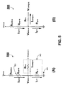
- FIG. 5A illustrates an equivalent circuit showing current flow when over-current condition occurs
- FIG. 5B illustrates an equivalent circuit showing current flow when under-current condition occurs according to one embodiment of the present invention
- FIG. 6 shows a detailed circuit diagram of an LED driver with current sink control according to another embodiment of the present invention.
- FIG. 7 shows a conventional circuit diagram of an integrated LED driving device
- FIG. 8 shows another conventional circuit diagram of a drive circuit.
- this invention in one aspect, relates to an LED driver with current sink control.
- the n-th current feedback unit 100 a representative current feedback unit of the plurality of current feedback units has an input 110 , a first output 120 , a second output 130 , a first reference line 310 for receiving a first supply voltage, a second reference line 320 for receiving a second supply voltage, a ground terminal 300 for coupling to the ground of the LED driver, an operational amplifier OP-n, a first resistor R cur-n , a second resistor R a-n , a third resistor R b-n , a fourth resistor R c-n , and a fifth resistor R d-n .
- Each of the first resistor R cur-n , the second resistor R a-n , the third resistor R b-n , the fourth resistor R c-n and the fifth resistor R d-n has a first terminal and a second terminal, respectively.
- the operational amplifier OP-n has a positive input 331 , a negative input 333 , an output 335 , a first power supply input 337 , and a second power supply input 339 .
- the first power supply input 337 is coupled to the first reference line 310 .
- the second power supply input 339 is coupled to the second reference line 320 .
- the output 335 is coupled to the second output 130 .
- the first terminal of the first resistor R cur-n is coupled to the first input 110 .
- the second terminal of the first resistor R cur-n is coupled to the first output 120 .
- the first terminal of the second resistor R a-n is coupled to the first terminal of the first resistor R cur-n .
- the second terminal of the second resistor R a-n is coupled to the positive input 331 of the operational amplifier OP-n.
- the first terminal of the third resistor R b-n is coupled to the second terminal of the first resistor R cur-n and the second terminal of the third resistor R b-n is coupled to the negative input of the operational amplifier OP-n.
- the first terminal of the fourth resistor R c-n is coupled to the negative input 333 of the operational amplifier OP-n.
- the second terminal of the fourth resistor R c-n is coupled to the output 335 of the operational amplifier OP-n and the second output 130 .
- the first terminal of the fifth resistor R d-n is coupled to the positive input 331 of the operational amplifier OP-n.
- the second terminal of the fifth resistor R d-n is coupled to the ground terminal 300 .
- the current flowing from the first input 110 to the first output 120 and the first resistor R cur-n is designated as I cur-n .
- the current I cur-n generates a voltage V Rcur-n across the first resistor R cur-n .
- the voltage V Rcur-n is multiplied through operational amplifier OP-n and the resistors R a-n , R b-n , R c-n , and R d-n .
- the voltage V cur-n is used for the closed circuit control and compensation for the current through n-th LED column.
- the n-th current compensation unit 200 a representative current compensation unit of the plurality of current feedback units has a first input 210 , a second input 220 , a third input 230 , a first reference line 310 for receiving a first supply voltage, a second reference line 320 for receiving a second supply voltage, a ground terminal 300 for connecting to the ground of the LED driver, a comparator COMP-n, a sixth resistor R g-n , a seventh resistor R f-n , and an eighth resistor R e-n .
- Each of the sixth resistor R g-n , the seventh resistor R f-n , and the eighth resistor R e-n has a first terminal and a second terminal, respectively.
- the comparator COMP-n has a positive input 341 , a negative input 343 , an output 345 , a first power supply input 347 , and a second power supply input 349 .
- the first power supply input 347 is coupled to the first reference line 310 .
- the second power supply input 349 is coupled to the second reference line 320 .
- the positive input 341 of the comparator COMP-n is coupled to the second input 220 and the negative input 343 of the comparator COMP-n is coupled to the third input 230 .
- the first terminal of the sixth resistor R g-n is coupled to the first input 210 .
- the second terminal of the sixth resistor R g-n is coupled to the ground terminal 300 .
- the first terminal of the seventh resistor R f-n is coupled to the first input 210 and the first terminal of the sixth resistor R g-n .
- the second terminal of the seventh resistor R f-n is coupled to the output 345 of the comparator COMP-n.
- the first terminal of the eighth resistor R e-n is coupled to the first reference line 310 and the first power supply input of the comparator COMP-n.
- the second terminal of the eighth resistor R e-n is coupled to the output 345 of the comparator COMP-n and the second terminal of the seventh resistor R f-n .
- Each LED column has a first terminal and a second terminal.
- the first terminal of an LED column is electrically coupled to the anode of the first LED D 1 .
- the cathode of each LED is electrically coupled to the anode of the anode of the next LED.
- the second terminal of the LED column is electrically coupled to the cathode of the M-th LED D M .
- SINK-n the second terminal of n-th LED column
- the LED array modules can be assembled with LED with various colors such as white color LED, red color LED, green color LED, blue color LED, or Red/Green/Blue combined color LED, and the like. For example, if a white color backlight is needed, N columns of M white color LED are used to construct the white LED backlight. If a tri-color (i.e. red, green and blue color) LED backlight is needed, N columns of M red color LED, N columns of M green color LED, and N columns of M blue color LED are used to form three LED columns with different color LED columns. Each of these three color LED columns is individually controlled and the corresponding red/green/blue color LED are combined to form a tri-color backlight for one pixel of the LCD screen.
- white color LED red color LED
- green color LED blue color LED
- Red/Green/Blue combined color LED Red/Green/Blue combined color LED
- a tri-color LED backlight can also be made with Red/Green/Blue combined color LED.
- each red, green and blue color LED is serially connected to the next same color LED to form three color LED columns such that each color LED column can be individually controlled.
- Each three color LED combination provides a three color backlight for each pixel of the LCD screen.
- the first output 120 and the second output 130 of the n-th current feedback unit 401 are coupled to the first input 210 and second input 220 of the n-th current compensation unit 451 , respectively.
- Each current feedback unit and each current compensation unit are provided with a first reference line 310 , a second reference line 320 , and a ground terminal 300 .
- the third input 230 of the n-th current compensation unit is electrically coupled to a current setting input V cur-set-n .
- the circuit diagrams shown in FIG. 3 and FIG. 4 in principle may be reduced to one equivalent circuit 500 as shown in FIGS. 5A and 5B .
- the equivalent circuit 500 has an LED column, the n-th LED column, having M LEDs connected in serial, a current feedback unit 100 , and a current compensation unit 200 .
- the equivalent circuit 500 is identical in both FIGS. 5A and 5B , but under different operating conditions, as further discussed below.
- the equivalent resistor R LED-N is the total combined resistance of the M LEDs in the n-th LED column.
- the resistor R cur-n is the first resistor of the n-th current feedback unit 100 shown in FIG. 1 .
- the R f-n is the resistance of the seventh resistor of the n-th current compensation unit 200 .
- R g-n is the sixth resistor of the n-th current compensation unit 200 .
- the equivalent circuit has a DC voltage V dcbus , and a ground terminal 300 .
- the node connecting to R cur-n , R f-n and R g-n is denoted as V sink-n .
- the current passing through n-th LED column is illustrated as I cur-n .
- I cur-n The current passing through n-th LED column is illustrated as I cur-n .
- over-current condition which is shown in FIG. 5A and further discussed below.
- under-current condition which is shown in FIG. 5B and further discussed below.
- the current I cur-n is sampled through the first resistor R cur-n and in doing so, the current I cur-n generates a voltage V Rcur-n across the first resistor R cur-n .
- the voltage output V cur-n of the operational amplifier OP-n is forwarded to the positive input of the comparator COMP-n (e.g. the second input 220 of the current compensation unit 200 shown in FIG. 2 ). This voltage V cur-n is compared to a predetermined voltage input as indicated as V cur-set-n .
- the current passing through n-th LED column I cur-n is greater than the ideal current level.
- the output of the comparator COMP-n is high.
- the voltage output V comp-n is accordingly increased and the compensation current I comp-n is injected into the node V sink-n such that the compensation current I comp flows from the output V comp-n of the n-th comparator COMP-n to V sink-n as shown in FIG. 5A .
- the current through the n-th LED column I cur-n is less than the ideal current level.
- the output of the comparator COMP-n is low.
- the voltage output V comp-n is accordingly decreased and the compensation current I comp-n is drawn from the node V sink-n such that the compensation current I comp flows from the node V sink-n to the output V comp-n of the n-th comparator COMP-n as shown in FIG. 5B .
- the sixth and seventh resistor R g-n and R f-n can be chosen to achieve maximum adjustment range of the output voltage V comp-n .
- the predetermined voltage V cur-set-n can be set to receive a same voltage for all LED columns to achieve a uniform compensation level, which provides a consistent and uniform color temperature of the backlight.
- each individual LED column can be independently adjusted through other digital signals to achieve maximum color gamut.
- the n-th LED column is electrically coupled in serial with the first resistor R cur-n .
- the current I cur-n flowing through these two components remains the same if the connection between these two components is swapped.
- FIG. 6 Another embodiment of the present invention is shown in FIG. 6 with such a configuration.
- an LED driver with current sink control include a DC power source V dcbus , N current feedback units, N LED columns having M LED connected in serial, and N current compensation units.
- Each LED column has a first terminal and a second terminal.
- the first terminal of an LED column is electrically coupled to the anode of the first LED.
- the cathode of each LED is electrically coupled to the anode of the anode of the next LED.
- the second terminal of the LED column is electrically coupled to the cathode of the M-th LED.
- the first output of the n-th current feedback unit is electrically coupled to the first terminal of the n-th LED column.
- Each of the second terminals of the N LED columns is electrically coupled to the input of a corresponding n-th current compensation unit.
- the second output of the n-th current feedback unit is electrically coupled to the second input of respective n-th current compensation unit.
- circuit diagram according to the embodiment of the present invention shown in FIG. 6 can be reduced to similar equivalent circuits shown in FIGS. 5A and 5B for both over-current condition and under-current condition, respectively.
- the LED driver with current sink control shown in FIGS. 1-6 according to various embodiments of the present invention as shown in FIGS. 1-7 , has following advantages over currently available LED drivers:
Abstract
Description
V cur-n=(R c-n)×(V Rcur-n)/(R a-n) (1)
where Ra-n=Rb-n, and Rc-n=Rd-n. The voltage Vcur-n is used for the closed circuit control and compensation for the current through n-th LED column.
I g-n =I cur-n +I comp-n (2)
I g-n =I cur-n −I comp-n (3)
-
- the LED driver with current sink control can be assembled as discrete component circuit as well as an integrated circuit;
- the number of LED columns of an LED driver with current sink control can be adjusted for different sizes of LED backlight for an LCD screen;
- the LED driver with current sink control reduces power consumption, and increases the overall efficiency of an LED backlight system using the LED driver;
- the LED driver with current sink control can be used with large LED array modules and provides greater color gamut;
- the LED driver with current sink control provides large current compensation adjustment ranges;
- the LED driver with current sink control provides individually controllable current compensation for each individual LED column, where each Red/Blue/Green LED column is able to achieve overall color temperature compensation and control;
- the LED driver with current sink control can be used in combination with proper Application Specific Integrated Circuit (ASIC) image control signal is to control the brightness of the backlight LED array module to further enhance the quality of the image displayed on the LCD screen; and
- the LED driver with current sink control uses the current feedback and current compensation to precisely compensate and control the current through each LED column, to adjust the brightness of the image and compensate the color temperature of the image such that the resulted images have greater dynamic ranges of the brightness, contrast, and natural color temperature.
Claims (25)
Priority Applications (4)
| Application Number | Priority Date | Filing Date | Title |
|---|---|---|---|
| US11/737,343 US7714517B2 (en) | 2007-04-19 | 2007-04-19 | LED driver with current sink control and applications of the same |
| TW096133210A TWI374687B (en) | 2007-04-19 | 2007-09-06 | Current feedback circuits, current compensation circuits, light emitting drivers and backlight systems |
| JP2007295091A JP4971949B2 (en) | 2007-04-19 | 2007-11-14 | LIGHT EMITTING DIODE DRIVER WITH A DRIVE CURRENT STABILIZER CONTROL DEVICE AND BACKLIGHT SYSTEM USING THE LIGHT EMITTING DIODE DRIVER |
| CNB2007101667760A CN100550107C (en) | 2007-04-19 | 2007-11-19 | Current feedback and compensating circuit, light emitting diode drive device and back light system |
Applications Claiming Priority (1)
| Application Number | Priority Date | Filing Date | Title |
|---|---|---|---|
| US11/737,343 US7714517B2 (en) | 2007-04-19 | 2007-04-19 | LED driver with current sink control and applications of the same |
Publications (2)
| Publication Number | Publication Date |
|---|---|
| US20080258636A1 US20080258636A1 (en) | 2008-10-23 |
| US7714517B2 true US7714517B2 (en) | 2010-05-11 |
Family
ID=39547479
Family Applications (1)
| Application Number | Title | Priority Date | Filing Date |
|---|---|---|---|
| US11/737,343 Active 2028-07-30 US7714517B2 (en) | 2007-04-19 | 2007-04-19 | LED driver with current sink control and applications of the same |
Country Status (4)
| Country | Link |
|---|---|
| US (1) | US7714517B2 (en) |
| JP (1) | JP4971949B2 (en) |
| CN (1) | CN100550107C (en) |
| TW (1) | TWI374687B (en) |
Cited By (6)
| Publication number | Priority date | Publication date | Assignee | Title |
|---|---|---|---|---|
| US20100264847A1 (en) * | 2009-04-16 | 2010-10-21 | Ke-Horng Chen | Voltage converter, backlight module control system and control method thereof |
| US20110109246A1 (en) * | 2008-07-04 | 2011-05-12 | Osram Gesellschaft Mit Beschraenkter Haftung | Circuit configuration and method for operating at least one first and one second led |
| US20110266972A1 (en) * | 2010-04-28 | 2011-11-03 | National Semiconductor Corporation | Dynamic current equalization for light emitting diode (LED) and other applications |
| US20130093327A1 (en) * | 2011-10-13 | 2013-04-18 | Leadtrend Technology Corp. | Control methods for led chains |
| US20140225517A1 (en) * | 2013-02-12 | 2014-08-14 | Samsung Electronics Co., Ltd. | Light emitting device (led) array unit and led module comprising the same |
| US9030459B2 (en) | 2011-04-06 | 2015-05-12 | Samsung Display Co., Ltd. | Back light unit and display device including the same |
Families Citing this family (33)
| Publication number | Priority date | Publication date | Assignee | Title |
|---|---|---|---|---|
| US9071139B2 (en) | 2008-08-19 | 2015-06-30 | Advanced Analogic Technologies Incorporated | High current switching converter for LED applications |
| US8358085B2 (en) | 2009-01-13 | 2013-01-22 | Terralux, Inc. | Method and device for remote sensing and control of LED lights |
| US9326346B2 (en) | 2009-01-13 | 2016-04-26 | Terralux, Inc. | Method and device for remote sensing and control of LED lights |
| JP2010267481A (en) * | 2009-05-14 | 2010-11-25 | Hitachi Displays Ltd | Backlight device and display device |
| CN101932168B (en) * | 2009-06-25 | 2013-02-20 | 佛山普立华科技有限公司 | Led control circuit |
| CN101600285B (en) * | 2009-06-26 | 2012-10-24 | 苏州佳世达电通有限公司 | Liquid crystal display, backlight module and drive method thereof |
| US9429965B2 (en) | 2009-11-03 | 2016-08-30 | Advanced Analogic Technologies Incorporated | Multiple chip voltage feedback technique for driving LED's |
| US8344659B2 (en) * | 2009-11-06 | 2013-01-01 | Neofocal Systems, Inc. | System and method for lighting power and control system |
| CN103025337B (en) | 2009-11-17 | 2014-10-15 | 特锐拉克斯有限公司 | LED power-supply detection and control |
| US8334660B2 (en) * | 2010-05-19 | 2012-12-18 | Sct Technology, Ltd. | Light source driving circuit with low operating output voltage |
| CN101917807B (en) * | 2010-08-12 | 2013-11-06 | 聚辰半导体(上海)有限公司 | Driving system for light-emitting diode |
| US9342058B2 (en) | 2010-09-16 | 2016-05-17 | Terralux, Inc. | Communication with lighting units over a power bus |
| US9596738B2 (en) | 2010-09-16 | 2017-03-14 | Terralux, Inc. | Communication with lighting units over a power bus |
| JP2012103538A (en) * | 2010-11-11 | 2012-05-31 | Mitsumi Electric Co Ltd | Backlight device, image display system including the same device, and lighting system |
| US8997732B2 (en) * | 2010-12-15 | 2015-04-07 | General Electric Company | Method and apparatus for the thermal protection of LED light modules in a range hood appliance |
| TWI426823B (en) * | 2010-12-24 | 2014-02-11 | Au Optronics Corp | Terminal voltage control circuit for light emitting diode (led) string and led illumination device |
| JP2014507711A (en) * | 2011-01-12 | 2014-03-27 | シティー ユニバーシティ オブ ホンコン | Current balancing circuit and method |
| US8531164B2 (en) | 2011-04-04 | 2013-09-10 | Advanced Analogic Technologies Incorporated | Operational transconductance amplifier feedback mechanism for fixed feedback voltage regulators |
| US9577610B2 (en) * | 2011-04-05 | 2017-02-21 | Advanced Analogic Technologies Incorporated | Active LED voltage clamp |
| TWI430238B (en) | 2011-05-17 | 2014-03-11 | Realtek Semiconductor Corp | Operating circuit applying to backlight and associated method |
| CN102956202A (en) * | 2011-08-29 | 2013-03-06 | 通嘉科技股份有限公司 | Current control level, constant-current control system, and current control method |
| US9706610B2 (en) | 2011-10-18 | 2017-07-11 | Atmel Corporation | Driving circuits for light emitting elements |
| US8896231B2 (en) | 2011-12-16 | 2014-11-25 | Terralux, Inc. | Systems and methods of applying bleed circuits in LED lamps |
| US9426862B2 (en) * | 2012-04-12 | 2016-08-23 | Shenzhen China Star Optoelectronics Technology Co., Ltd. | LED backlight drive circuit, liquid crystal display device and driving method |
| RU2632186C2 (en) * | 2012-06-14 | 2017-10-04 | Филипс Лайтинг Холдинг Б.В. | Self-regulating lighting exciter for exciting light sources and lighting unit including self-regulating lighting exciter |
| CN103634976A (en) * | 2012-08-29 | 2014-03-12 | 深圳富泰宏精密工业有限公司 | Backlight module control circuit |
| CN102930830B (en) * | 2012-10-30 | 2016-01-20 | 南京中电熊猫液晶显示科技有限公司 | A kind of method improving scanning backlight inequality |
| CN103854596A (en) * | 2012-11-29 | 2014-06-11 | 利亚德光电股份有限公司 | Led display |
| US9265119B2 (en) | 2013-06-17 | 2016-02-16 | Terralux, Inc. | Systems and methods for providing thermal fold-back to LED lights |
| TWI587738B (en) * | 2016-05-02 | 2017-06-11 | 友達光電股份有限公司 | Detection and correction device |
| US10877314B2 (en) * | 2018-09-27 | 2020-12-29 | Apple Inc. | Methods and apparatus for controlling display backlight |
| TWI806476B (en) * | 2022-03-07 | 2023-06-21 | 友達光電股份有限公司 | Light emitting diode display module |
| CN115987392B (en) * | 2023-02-16 | 2023-06-09 | 南昌大学 | POE-based high-speed visible light communication system and method |
Citations (6)
| Publication number | Priority date | Publication date | Assignee | Title |
|---|---|---|---|---|
| US4104533A (en) | 1977-02-28 | 1978-08-01 | The United States Of America As Represented By The Secretary Of The Navy | Wideband optical isolator |
| US6490512B1 (en) | 1998-11-13 | 2002-12-03 | Hella Kg Hueck & Co. | Diagnostic system for an LED lamp for a motor vehicle |
| US6621235B2 (en) | 2001-08-03 | 2003-09-16 | Koninklijke Philips Electronics N.V. | Integrated LED driving device with current sharing for multiple LED strings |
| US6864867B2 (en) | 2001-03-28 | 2005-03-08 | Patent-Treuhand-Gesellschaft für elektrische Glühlampen mbH | Drive circuit for an LED array |
| US7471287B2 (en) * | 2006-11-01 | 2008-12-30 | Chunghwa Picture Tubes, Ltd. | Light source driving circuit for driving light emitting diode components and driving method thereof |
| US7557520B2 (en) * | 2006-10-18 | 2009-07-07 | Chunghwa Picture Tubes, Ltd. | Light source driving circuit |
Family Cites Families (2)
| Publication number | Priority date | Publication date | Assignee | Title |
|---|---|---|---|---|
| JP2523141B2 (en) * | 1987-10-02 | 1996-08-07 | 富士通株式会社 | Light emitting element drive circuit |
| JP4123183B2 (en) * | 2004-04-20 | 2008-07-23 | ソニー株式会社 | Constant current drive device, backlight light source device, and color liquid crystal display device |
-
2007
- 2007-04-19 US US11/737,343 patent/US7714517B2/en active Active
- 2007-09-06 TW TW096133210A patent/TWI374687B/en active
- 2007-11-14 JP JP2007295091A patent/JP4971949B2/en active Active
- 2007-11-19 CN CNB2007101667760A patent/CN100550107C/en active Active
Patent Citations (6)
| Publication number | Priority date | Publication date | Assignee | Title |
|---|---|---|---|---|
| US4104533A (en) | 1977-02-28 | 1978-08-01 | The United States Of America As Represented By The Secretary Of The Navy | Wideband optical isolator |
| US6490512B1 (en) | 1998-11-13 | 2002-12-03 | Hella Kg Hueck & Co. | Diagnostic system for an LED lamp for a motor vehicle |
| US6864867B2 (en) | 2001-03-28 | 2005-03-08 | Patent-Treuhand-Gesellschaft für elektrische Glühlampen mbH | Drive circuit for an LED array |
| US6621235B2 (en) | 2001-08-03 | 2003-09-16 | Koninklijke Philips Electronics N.V. | Integrated LED driving device with current sharing for multiple LED strings |
| US7557520B2 (en) * | 2006-10-18 | 2009-07-07 | Chunghwa Picture Tubes, Ltd. | Light source driving circuit |
| US7471287B2 (en) * | 2006-11-01 | 2008-12-30 | Chunghwa Picture Tubes, Ltd. | Light source driving circuit for driving light emitting diode components and driving method thereof |
Cited By (11)
| Publication number | Priority date | Publication date | Assignee | Title |
|---|---|---|---|---|
| US20110109246A1 (en) * | 2008-07-04 | 2011-05-12 | Osram Gesellschaft Mit Beschraenkter Haftung | Circuit configuration and method for operating at least one first and one second led |
| US8547031B2 (en) | 2008-07-04 | 2013-10-01 | Osram Gesellschaft Mit Beschraenkter Haftung | Circuit configuration and method for operating at least one first and one second LED |
| US20100264847A1 (en) * | 2009-04-16 | 2010-10-21 | Ke-Horng Chen | Voltage converter, backlight module control system and control method thereof |
| US8193725B2 (en) * | 2009-04-16 | 2012-06-05 | Chunghwa Picture Tubes, Ltd. | Voltage converter, backlight module control system and control method thereof |
| US20110266972A1 (en) * | 2010-04-28 | 2011-11-03 | National Semiconductor Corporation | Dynamic current equalization for light emitting diode (LED) and other applications |
| US8350498B2 (en) * | 2010-04-28 | 2013-01-08 | National Semiconductor Corporation | Dynamic current equalization for light emitting diode (LED) and other applications |
| US9030459B2 (en) | 2011-04-06 | 2015-05-12 | Samsung Display Co., Ltd. | Back light unit and display device including the same |
| US20130093327A1 (en) * | 2011-10-13 | 2013-04-18 | Leadtrend Technology Corp. | Control methods for led chains |
| US20140225517A1 (en) * | 2013-02-12 | 2014-08-14 | Samsung Electronics Co., Ltd. | Light emitting device (led) array unit and led module comprising the same |
| US9326337B2 (en) * | 2013-02-12 | 2016-04-26 | Samsung Electronics Co., Ltd. | Light emitting device (LED) array unit and LED module comprising the same |
| US9603214B2 (en) | 2013-02-12 | 2017-03-21 | Samsung Electronics Co., Ltd. | Light emitting device (LED) array unit and LED module comprising the same |
Also Published As
| Publication number | Publication date |
|---|---|
| TW200843555A (en) | 2008-11-01 |
| JP2008270713A (en) | 2008-11-06 |
| CN101197109A (en) | 2008-06-11 |
| CN100550107C (en) | 2009-10-14 |
| JP4971949B2 (en) | 2012-07-11 |
| TWI374687B (en) | 2012-10-11 |
| US20080258636A1 (en) | 2008-10-23 |
Similar Documents
| Publication | Publication Date | Title |
|---|---|---|
| US7714517B2 (en) | LED driver with current sink control and applications of the same | |
| KR101164245B1 (en) | Light emitting element drive device and display system | |
| US7723922B2 (en) | Light emitting diode driving device | |
| US8922736B2 (en) | Liquid crystal display device | |
| US8941331B2 (en) | Solid state lighting panels with variable voltage boost current sources | |
| US8373346B2 (en) | Solid state lighting system and a driver integrated circuit for driving light emitting semiconductor devices | |
| TW200713165A (en) | LED light source for backlighting with integrated electronics | |
| US20060176411A1 (en) | Constant current driver, back light source and color liquid crystal display | |
| JP4720099B2 (en) | Constant current drive device, backlight light source device, and color liquid crystal display device | |
| US8159148B2 (en) | Light emitting diode light source module | |
| JP2007165161A (en) | Led illumination device, led backlight device, and image display device | |
| JP2007199648A (en) | Driver and method for driving a semiconductor light emitting device array | |
| CN102254526B (en) | Light-emitting element driving device and display device | |
| US10939524B1 (en) | Driving LEDs in backlight for flat panel display | |
| JP2007134430A (en) | Led illumination apparatus, led backlight, and image display device | |
| JP2008304694A (en) | Inner illuminating type sign | |
| JP2011514990A (en) | Configuration of LED-based flexible video screen current regulator |
Legal Events
| Date | Code | Title | Description |
|---|---|---|---|
| AS | Assignment |
Owner name: AU OPTRONICS CORPORATION, TAIWAN Free format text: ASSIGNMENT OF ASSIGNORS INTEREST;ASSIGNORS:SHIH, CHAOJIAN;LEE, TSUNG-SHIUN;SUN, CHIA-HUNG;AND OTHERS;REEL/FRAME:019183/0069 Effective date: 20070416 Owner name: AU OPTRONICS CORPORATION,TAIWAN Free format text: ASSIGNMENT OF ASSIGNORS INTEREST;ASSIGNORS:SHIH, CHAOJIAN;LEE, TSUNG-SHIUN;SUN, CHIA-HUNG;AND OTHERS;REEL/FRAME:019183/0069 Effective date: 20070416 |
|
| AS | Assignment |
Owner name: AU OPTRONICS CORPORATION, TAIWAN Free format text: ASSIGNMENT OF ASSIGNORS INTEREST;ASSIGNORS:SHIH, HUNG-MIN;LEE, TSUNG-SHIUN;SUN, CHIA-HUNG;AND OTHERS;REEL/FRAME:019187/0922 Effective date: 20070416 Owner name: AU OPTRONICS CORPORATION,TAIWAN Free format text: ASSIGNMENT OF ASSIGNORS INTEREST;ASSIGNORS:SHIH, HUNG-MIN;LEE, TSUNG-SHIUN;SUN, CHIA-HUNG;AND OTHERS;REEL/FRAME:019187/0922 Effective date: 20070416 |
|
| STCF | Information on status: patent grant |
Free format text: PATENTED CASE |
|
| FPAY | Fee payment |
Year of fee payment: 4 |
|
| MAFP | Maintenance fee payment |
Free format text: PAYMENT OF MAINTENANCE FEE, 8TH YEAR, LARGE ENTITY (ORIGINAL EVENT CODE: M1552) Year of fee payment: 8 |
|
| MAFP | Maintenance fee payment |
Free format text: PAYMENT OF MAINTENANCE FEE, 12TH YEAR, LARGE ENTITY (ORIGINAL EVENT CODE: M1553); ENTITY STATUS OF PATENT OWNER: LARGE ENTITY Year of fee payment: 12 |