US7657350B2 - Method of controlling engine stop-start operation for heavy-duty hybrid-electric and hybrid-hydraulic vehicles - Google Patents
Method of controlling engine stop-start operation for heavy-duty hybrid-electric and hybrid-hydraulic vehicles Download PDFInfo
- Publication number
- US7657350B2 US7657350B2 US11/948,760 US94876007A US7657350B2 US 7657350 B2 US7657350 B2 US 7657350B2 US 94876007 A US94876007 A US 94876007A US 7657350 B2 US7657350 B2 US 7657350B2
- Authority
- US
- United States
- Prior art keywords
- energy storage
- engine
- vehicle
- charge
- state
- Prior art date
- Legal status (The legal status is an assumption and is not a legal conclusion. Google has not performed a legal analysis and makes no representation as to the accuracy of the status listed.)
- Expired - Fee Related
Links
Images


Classifications
-
- B—PERFORMING OPERATIONS; TRANSPORTING
- B60—VEHICLES IN GENERAL
- B60W—CONJOINT CONTROL OF VEHICLE SUB-UNITS OF DIFFERENT TYPE OR DIFFERENT FUNCTION; CONTROL SYSTEMS SPECIALLY ADAPTED FOR HYBRID VEHICLES; ROAD VEHICLE DRIVE CONTROL SYSTEMS FOR PURPOSES NOT RELATED TO THE CONTROL OF A PARTICULAR SUB-UNIT
- B60W20/00—Control systems specially adapted for hybrid vehicles
-
- B—PERFORMING OPERATIONS; TRANSPORTING
- B60—VEHICLES IN GENERAL
- B60K—ARRANGEMENT OR MOUNTING OF PROPULSION UNITS OR OF TRANSMISSIONS IN VEHICLES; ARRANGEMENT OR MOUNTING OF PLURAL DIVERSE PRIME-MOVERS IN VEHICLES; AUXILIARY DRIVES FOR VEHICLES; INSTRUMENTATION OR DASHBOARDS FOR VEHICLES; ARRANGEMENTS IN CONNECTION WITH COOLING, AIR INTAKE, GAS EXHAUST OR FUEL SUPPLY OF PROPULSION UNITS IN VEHICLES
- B60K6/00—Arrangement or mounting of plural diverse prime-movers for mutual or common propulsion, e.g. hybrid propulsion systems comprising electric motors and internal combustion engines ; Control systems therefor, i.e. systems controlling two or more prime movers, or controlling one of these prime movers and any of the transmission, drive or drive units Informative references: mechanical gearings with secondary electric drive F16H3/72; arrangements for handling mechanical energy structurally associated with the dynamo-electric machine H02K7/00; machines comprising structurally interrelated motor and generator parts H02K51/00; dynamo-electric machines not otherwise provided for in H02K see H02K99/00
- B60K6/08—Prime-movers comprising combustion engines and mechanical or fluid energy storing means
- B60K6/12—Prime-movers comprising combustion engines and mechanical or fluid energy storing means by means of a chargeable fluidic accumulator
-
- B—PERFORMING OPERATIONS; TRANSPORTING
- B60—VEHICLES IN GENERAL
- B60K—ARRANGEMENT OR MOUNTING OF PROPULSION UNITS OR OF TRANSMISSIONS IN VEHICLES; ARRANGEMENT OR MOUNTING OF PLURAL DIVERSE PRIME-MOVERS IN VEHICLES; AUXILIARY DRIVES FOR VEHICLES; INSTRUMENTATION OR DASHBOARDS FOR VEHICLES; ARRANGEMENTS IN CONNECTION WITH COOLING, AIR INTAKE, GAS EXHAUST OR FUEL SUPPLY OF PROPULSION UNITS IN VEHICLES
- B60K6/00—Arrangement or mounting of plural diverse prime-movers for mutual or common propulsion, e.g. hybrid propulsion systems comprising electric motors and internal combustion engines ; Control systems therefor, i.e. systems controlling two or more prime movers, or controlling one of these prime movers and any of the transmission, drive or drive units Informative references: mechanical gearings with secondary electric drive F16H3/72; arrangements for handling mechanical energy structurally associated with the dynamo-electric machine H02K7/00; machines comprising structurally interrelated motor and generator parts H02K51/00; dynamo-electric machines not otherwise provided for in H02K see H02K99/00
- B60K6/20—Arrangement or mounting of plural diverse prime-movers for mutual or common propulsion, e.g. hybrid propulsion systems comprising electric motors and internal combustion engines ; Control systems therefor, i.e. systems controlling two or more prime movers, or controlling one of these prime movers and any of the transmission, drive or drive units Informative references: mechanical gearings with secondary electric drive F16H3/72; arrangements for handling mechanical energy structurally associated with the dynamo-electric machine H02K7/00; machines comprising structurally interrelated motor and generator parts H02K51/00; dynamo-electric machines not otherwise provided for in H02K see H02K99/00 the prime-movers consisting of electric motors and internal combustion engines, e.g. HEVs
- B60K6/22—Arrangement or mounting of plural diverse prime-movers for mutual or common propulsion, e.g. hybrid propulsion systems comprising electric motors and internal combustion engines ; Control systems therefor, i.e. systems controlling two or more prime movers, or controlling one of these prime movers and any of the transmission, drive or drive units Informative references: mechanical gearings with secondary electric drive F16H3/72; arrangements for handling mechanical energy structurally associated with the dynamo-electric machine H02K7/00; machines comprising structurally interrelated motor and generator parts H02K51/00; dynamo-electric machines not otherwise provided for in H02K see H02K99/00 the prime-movers consisting of electric motors and internal combustion engines, e.g. HEVs characterised by apparatus, components or means specially adapted for HEVs
- B60K6/26—Arrangement or mounting of plural diverse prime-movers for mutual or common propulsion, e.g. hybrid propulsion systems comprising electric motors and internal combustion engines ; Control systems therefor, i.e. systems controlling two or more prime movers, or controlling one of these prime movers and any of the transmission, drive or drive units Informative references: mechanical gearings with secondary electric drive F16H3/72; arrangements for handling mechanical energy structurally associated with the dynamo-electric machine H02K7/00; machines comprising structurally interrelated motor and generator parts H02K51/00; dynamo-electric machines not otherwise provided for in H02K see H02K99/00 the prime-movers consisting of electric motors and internal combustion engines, e.g. HEVs characterised by apparatus, components or means specially adapted for HEVs characterised by the motors or the generators
-
- B—PERFORMING OPERATIONS; TRANSPORTING
- B60—VEHICLES IN GENERAL
- B60K—ARRANGEMENT OR MOUNTING OF PROPULSION UNITS OR OF TRANSMISSIONS IN VEHICLES; ARRANGEMENT OR MOUNTING OF PLURAL DIVERSE PRIME-MOVERS IN VEHICLES; AUXILIARY DRIVES FOR VEHICLES; INSTRUMENTATION OR DASHBOARDS FOR VEHICLES; ARRANGEMENTS IN CONNECTION WITH COOLING, AIR INTAKE, GAS EXHAUST OR FUEL SUPPLY OF PROPULSION UNITS IN VEHICLES
- B60K6/00—Arrangement or mounting of plural diverse prime-movers for mutual or common propulsion, e.g. hybrid propulsion systems comprising electric motors and internal combustion engines ; Control systems therefor, i.e. systems controlling two or more prime movers, or controlling one of these prime movers and any of the transmission, drive or drive units Informative references: mechanical gearings with secondary electric drive F16H3/72; arrangements for handling mechanical energy structurally associated with the dynamo-electric machine H02K7/00; machines comprising structurally interrelated motor and generator parts H02K51/00; dynamo-electric machines not otherwise provided for in H02K see H02K99/00
- B60K6/20—Arrangement or mounting of plural diverse prime-movers for mutual or common propulsion, e.g. hybrid propulsion systems comprising electric motors and internal combustion engines ; Control systems therefor, i.e. systems controlling two or more prime movers, or controlling one of these prime movers and any of the transmission, drive or drive units Informative references: mechanical gearings with secondary electric drive F16H3/72; arrangements for handling mechanical energy structurally associated with the dynamo-electric machine H02K7/00; machines comprising structurally interrelated motor and generator parts H02K51/00; dynamo-electric machines not otherwise provided for in H02K see H02K99/00 the prime-movers consisting of electric motors and internal combustion engines, e.g. HEVs
- B60K6/42—Arrangement or mounting of plural diverse prime-movers for mutual or common propulsion, e.g. hybrid propulsion systems comprising electric motors and internal combustion engines ; Control systems therefor, i.e. systems controlling two or more prime movers, or controlling one of these prime movers and any of the transmission, drive or drive units Informative references: mechanical gearings with secondary electric drive F16H3/72; arrangements for handling mechanical energy structurally associated with the dynamo-electric machine H02K7/00; machines comprising structurally interrelated motor and generator parts H02K51/00; dynamo-electric machines not otherwise provided for in H02K see H02K99/00 the prime-movers consisting of electric motors and internal combustion engines, e.g. HEVs characterised by the architecture of the hybrid electric vehicle
- B60K6/46—Series type
-
- B—PERFORMING OPERATIONS; TRANSPORTING
- B60—VEHICLES IN GENERAL
- B60K—ARRANGEMENT OR MOUNTING OF PROPULSION UNITS OR OF TRANSMISSIONS IN VEHICLES; ARRANGEMENT OR MOUNTING OF PLURAL DIVERSE PRIME-MOVERS IN VEHICLES; AUXILIARY DRIVES FOR VEHICLES; INSTRUMENTATION OR DASHBOARDS FOR VEHICLES; ARRANGEMENTS IN CONNECTION WITH COOLING, AIR INTAKE, GAS EXHAUST OR FUEL SUPPLY OF PROPULSION UNITS IN VEHICLES
- B60K6/00—Arrangement or mounting of plural diverse prime-movers for mutual or common propulsion, e.g. hybrid propulsion systems comprising electric motors and internal combustion engines ; Control systems therefor, i.e. systems controlling two or more prime movers, or controlling one of these prime movers and any of the transmission, drive or drive units Informative references: mechanical gearings with secondary electric drive F16H3/72; arrangements for handling mechanical energy structurally associated with the dynamo-electric machine H02K7/00; machines comprising structurally interrelated motor and generator parts H02K51/00; dynamo-electric machines not otherwise provided for in H02K see H02K99/00
- B60K6/20—Arrangement or mounting of plural diverse prime-movers for mutual or common propulsion, e.g. hybrid propulsion systems comprising electric motors and internal combustion engines ; Control systems therefor, i.e. systems controlling two or more prime movers, or controlling one of these prime movers and any of the transmission, drive or drive units Informative references: mechanical gearings with secondary electric drive F16H3/72; arrangements for handling mechanical energy structurally associated with the dynamo-electric machine H02K7/00; machines comprising structurally interrelated motor and generator parts H02K51/00; dynamo-electric machines not otherwise provided for in H02K see H02K99/00 the prime-movers consisting of electric motors and internal combustion engines, e.g. HEVs
- B60K6/42—Arrangement or mounting of plural diverse prime-movers for mutual or common propulsion, e.g. hybrid propulsion systems comprising electric motors and internal combustion engines ; Control systems therefor, i.e. systems controlling two or more prime movers, or controlling one of these prime movers and any of the transmission, drive or drive units Informative references: mechanical gearings with secondary electric drive F16H3/72; arrangements for handling mechanical energy structurally associated with the dynamo-electric machine H02K7/00; machines comprising structurally interrelated motor and generator parts H02K51/00; dynamo-electric machines not otherwise provided for in H02K see H02K99/00 the prime-movers consisting of electric motors and internal combustion engines, e.g. HEVs characterised by the architecture of the hybrid electric vehicle
- B60K6/48—Parallel type
-
- B—PERFORMING OPERATIONS; TRANSPORTING
- B60—VEHICLES IN GENERAL
- B60L—PROPULSION OF ELECTRICALLY-PROPELLED VEHICLES; SUPPLYING ELECTRIC POWER FOR AUXILIARY EQUIPMENT OF ELECTRICALLY-PROPELLED VEHICLES; ELECTRODYNAMIC BRAKE SYSTEMS FOR VEHICLES IN GENERAL; MAGNETIC SUSPENSION OR LEVITATION FOR VEHICLES; MONITORING OPERATING VARIABLES OF ELECTRICALLY-PROPELLED VEHICLES; ELECTRIC SAFETY DEVICES FOR ELECTRICALLY-PROPELLED VEHICLES
- B60L1/00—Supplying electric power to auxiliary equipment of vehicles
- B60L1/003—Supplying electric power to auxiliary equipment of vehicles to auxiliary motors, e.g. for pumps, compressors
-
- B—PERFORMING OPERATIONS; TRANSPORTING
- B60—VEHICLES IN GENERAL
- B60L—PROPULSION OF ELECTRICALLY-PROPELLED VEHICLES; SUPPLYING ELECTRIC POWER FOR AUXILIARY EQUIPMENT OF ELECTRICALLY-PROPELLED VEHICLES; ELECTRODYNAMIC BRAKE SYSTEMS FOR VEHICLES IN GENERAL; MAGNETIC SUSPENSION OR LEVITATION FOR VEHICLES; MONITORING OPERATING VARIABLES OF ELECTRICALLY-PROPELLED VEHICLES; ELECTRIC SAFETY DEVICES FOR ELECTRICALLY-PROPELLED VEHICLES
- B60L50/00—Electric propulsion with power supplied within the vehicle
- B60L50/10—Electric propulsion with power supplied within the vehicle using propulsion power supplied by engine-driven generators, e.g. generators driven by combustion engines
- B60L50/16—Electric propulsion with power supplied within the vehicle using propulsion power supplied by engine-driven generators, e.g. generators driven by combustion engines with provision for separate direct mechanical propulsion
-
- B—PERFORMING OPERATIONS; TRANSPORTING
- B60—VEHICLES IN GENERAL
- B60L—PROPULSION OF ELECTRICALLY-PROPELLED VEHICLES; SUPPLYING ELECTRIC POWER FOR AUXILIARY EQUIPMENT OF ELECTRICALLY-PROPELLED VEHICLES; ELECTRODYNAMIC BRAKE SYSTEMS FOR VEHICLES IN GENERAL; MAGNETIC SUSPENSION OR LEVITATION FOR VEHICLES; MONITORING OPERATING VARIABLES OF ELECTRICALLY-PROPELLED VEHICLES; ELECTRIC SAFETY DEVICES FOR ELECTRICALLY-PROPELLED VEHICLES
- B60L50/00—Electric propulsion with power supplied within the vehicle
- B60L50/50—Electric propulsion with power supplied within the vehicle using propulsion power supplied by batteries or fuel cells
- B60L50/60—Electric propulsion with power supplied within the vehicle using propulsion power supplied by batteries or fuel cells using power supplied by batteries
- B60L50/61—Electric propulsion with power supplied within the vehicle using propulsion power supplied by batteries or fuel cells using power supplied by batteries by batteries charged by engine-driven generators, e.g. series hybrid electric vehicles
-
- B—PERFORMING OPERATIONS; TRANSPORTING
- B60—VEHICLES IN GENERAL
- B60L—PROPULSION OF ELECTRICALLY-PROPELLED VEHICLES; SUPPLYING ELECTRIC POWER FOR AUXILIARY EQUIPMENT OF ELECTRICALLY-PROPELLED VEHICLES; ELECTRODYNAMIC BRAKE SYSTEMS FOR VEHICLES IN GENERAL; MAGNETIC SUSPENSION OR LEVITATION FOR VEHICLES; MONITORING OPERATING VARIABLES OF ELECTRICALLY-PROPELLED VEHICLES; ELECTRIC SAFETY DEVICES FOR ELECTRICALLY-PROPELLED VEHICLES
- B60L58/00—Methods or circuit arrangements for monitoring or controlling batteries or fuel cells, specially adapted for electric vehicles
- B60L58/10—Methods or circuit arrangements for monitoring or controlling batteries or fuel cells, specially adapted for electric vehicles for monitoring or controlling batteries
- B60L58/12—Methods or circuit arrangements for monitoring or controlling batteries or fuel cells, specially adapted for electric vehicles for monitoring or controlling batteries responding to state of charge [SoC]
-
- B—PERFORMING OPERATIONS; TRANSPORTING
- B60—VEHICLES IN GENERAL
- B60L—PROPULSION OF ELECTRICALLY-PROPELLED VEHICLES; SUPPLYING ELECTRIC POWER FOR AUXILIARY EQUIPMENT OF ELECTRICALLY-PROPELLED VEHICLES; ELECTRODYNAMIC BRAKE SYSTEMS FOR VEHICLES IN GENERAL; MAGNETIC SUSPENSION OR LEVITATION FOR VEHICLES; MONITORING OPERATING VARIABLES OF ELECTRICALLY-PROPELLED VEHICLES; ELECTRIC SAFETY DEVICES FOR ELECTRICALLY-PROPELLED VEHICLES
- B60L58/00—Methods or circuit arrangements for monitoring or controlling batteries or fuel cells, specially adapted for electric vehicles
- B60L58/10—Methods or circuit arrangements for monitoring or controlling batteries or fuel cells, specially adapted for electric vehicles for monitoring or controlling batteries
- B60L58/18—Methods or circuit arrangements for monitoring or controlling batteries or fuel cells, specially adapted for electric vehicles for monitoring or controlling batteries of two or more battery modules
- B60L58/20—Methods or circuit arrangements for monitoring or controlling batteries or fuel cells, specially adapted for electric vehicles for monitoring or controlling batteries of two or more battery modules having different nominal voltages
-
- B—PERFORMING OPERATIONS; TRANSPORTING
- B60—VEHICLES IN GENERAL
- B60L—PROPULSION OF ELECTRICALLY-PROPELLED VEHICLES; SUPPLYING ELECTRIC POWER FOR AUXILIARY EQUIPMENT OF ELECTRICALLY-PROPELLED VEHICLES; ELECTRODYNAMIC BRAKE SYSTEMS FOR VEHICLES IN GENERAL; MAGNETIC SUSPENSION OR LEVITATION FOR VEHICLES; MONITORING OPERATING VARIABLES OF ELECTRICALLY-PROPELLED VEHICLES; ELECTRIC SAFETY DEVICES FOR ELECTRICALLY-PROPELLED VEHICLES
- B60L7/00—Electrodynamic brake systems for vehicles in general
- B60L7/10—Dynamic electric regenerative braking
- B60L7/14—Dynamic electric regenerative braking for vehicles propelled by ac motors
-
- B—PERFORMING OPERATIONS; TRANSPORTING
- B60—VEHICLES IN GENERAL
- B60W—CONJOINT CONTROL OF VEHICLE SUB-UNITS OF DIFFERENT TYPE OR DIFFERENT FUNCTION; CONTROL SYSTEMS SPECIALLY ADAPTED FOR HYBRID VEHICLES; ROAD VEHICLE DRIVE CONTROL SYSTEMS FOR PURPOSES NOT RELATED TO THE CONTROL OF A PARTICULAR SUB-UNIT
- B60W10/00—Conjoint control of vehicle sub-units of different type or different function
- B60W10/04—Conjoint control of vehicle sub-units of different type or different function including control of propulsion units
- B60W10/06—Conjoint control of vehicle sub-units of different type or different function including control of propulsion units including control of combustion engines
-
- B—PERFORMING OPERATIONS; TRANSPORTING
- B60—VEHICLES IN GENERAL
- B60W—CONJOINT CONTROL OF VEHICLE SUB-UNITS OF DIFFERENT TYPE OR DIFFERENT FUNCTION; CONTROL SYSTEMS SPECIALLY ADAPTED FOR HYBRID VEHICLES; ROAD VEHICLE DRIVE CONTROL SYSTEMS FOR PURPOSES NOT RELATED TO THE CONTROL OF A PARTICULAR SUB-UNIT
- B60W10/00—Conjoint control of vehicle sub-units of different type or different function
- B60W10/04—Conjoint control of vehicle sub-units of different type or different function including control of propulsion units
- B60W10/08—Conjoint control of vehicle sub-units of different type or different function including control of propulsion units including control of electric propulsion units, e.g. motors or generators
-
- B—PERFORMING OPERATIONS; TRANSPORTING
- B60—VEHICLES IN GENERAL
- B60W—CONJOINT CONTROL OF VEHICLE SUB-UNITS OF DIFFERENT TYPE OR DIFFERENT FUNCTION; CONTROL SYSTEMS SPECIALLY ADAPTED FOR HYBRID VEHICLES; ROAD VEHICLE DRIVE CONTROL SYSTEMS FOR PURPOSES NOT RELATED TO THE CONTROL OF A PARTICULAR SUB-UNIT
- B60W10/00—Conjoint control of vehicle sub-units of different type or different function
- B60W10/24—Conjoint control of vehicle sub-units of different type or different function including control of energy storage means
- B60W10/26—Conjoint control of vehicle sub-units of different type or different function including control of energy storage means for electrical energy, e.g. batteries or capacitors
-
- B—PERFORMING OPERATIONS; TRANSPORTING
- B60—VEHICLES IN GENERAL
- B60K—ARRANGEMENT OR MOUNTING OF PROPULSION UNITS OR OF TRANSMISSIONS IN VEHICLES; ARRANGEMENT OR MOUNTING OF PLURAL DIVERSE PRIME-MOVERS IN VEHICLES; AUXILIARY DRIVES FOR VEHICLES; INSTRUMENTATION OR DASHBOARDS FOR VEHICLES; ARRANGEMENTS IN CONNECTION WITH COOLING, AIR INTAKE, GAS EXHAUST OR FUEL SUPPLY OF PROPULSION UNITS IN VEHICLES
- B60K6/00—Arrangement or mounting of plural diverse prime-movers for mutual or common propulsion, e.g. hybrid propulsion systems comprising electric motors and internal combustion engines ; Control systems therefor, i.e. systems controlling two or more prime movers, or controlling one of these prime movers and any of the transmission, drive or drive units Informative references: mechanical gearings with secondary electric drive F16H3/72; arrangements for handling mechanical energy structurally associated with the dynamo-electric machine H02K7/00; machines comprising structurally interrelated motor and generator parts H02K51/00; dynamo-electric machines not otherwise provided for in H02K see H02K99/00
- B60K6/20—Arrangement or mounting of plural diverse prime-movers for mutual or common propulsion, e.g. hybrid propulsion systems comprising electric motors and internal combustion engines ; Control systems therefor, i.e. systems controlling two or more prime movers, or controlling one of these prime movers and any of the transmission, drive or drive units Informative references: mechanical gearings with secondary electric drive F16H3/72; arrangements for handling mechanical energy structurally associated with the dynamo-electric machine H02K7/00; machines comprising structurally interrelated motor and generator parts H02K51/00; dynamo-electric machines not otherwise provided for in H02K see H02K99/00 the prime-movers consisting of electric motors and internal combustion engines, e.g. HEVs
- B60K6/22—Arrangement or mounting of plural diverse prime-movers for mutual or common propulsion, e.g. hybrid propulsion systems comprising electric motors and internal combustion engines ; Control systems therefor, i.e. systems controlling two or more prime movers, or controlling one of these prime movers and any of the transmission, drive or drive units Informative references: mechanical gearings with secondary electric drive F16H3/72; arrangements for handling mechanical energy structurally associated with the dynamo-electric machine H02K7/00; machines comprising structurally interrelated motor and generator parts H02K51/00; dynamo-electric machines not otherwise provided for in H02K see H02K99/00 the prime-movers consisting of electric motors and internal combustion engines, e.g. HEVs characterised by apparatus, components or means specially adapted for HEVs
- B60K6/26—Arrangement or mounting of plural diverse prime-movers for mutual or common propulsion, e.g. hybrid propulsion systems comprising electric motors and internal combustion engines ; Control systems therefor, i.e. systems controlling two or more prime movers, or controlling one of these prime movers and any of the transmission, drive or drive units Informative references: mechanical gearings with secondary electric drive F16H3/72; arrangements for handling mechanical energy structurally associated with the dynamo-electric machine H02K7/00; machines comprising structurally interrelated motor and generator parts H02K51/00; dynamo-electric machines not otherwise provided for in H02K see H02K99/00 the prime-movers consisting of electric motors and internal combustion engines, e.g. HEVs characterised by apparatus, components or means specially adapted for HEVs characterised by the motors or the generators
- B60K2006/268—Electric drive motor starts the engine, i.e. used as starter motor
-
- B—PERFORMING OPERATIONS; TRANSPORTING
- B60—VEHICLES IN GENERAL
- B60L—PROPULSION OF ELECTRICALLY-PROPELLED VEHICLES; SUPPLYING ELECTRIC POWER FOR AUXILIARY EQUIPMENT OF ELECTRICALLY-PROPELLED VEHICLES; ELECTRODYNAMIC BRAKE SYSTEMS FOR VEHICLES IN GENERAL; MAGNETIC SUSPENSION OR LEVITATION FOR VEHICLES; MONITORING OPERATING VARIABLES OF ELECTRICALLY-PROPELLED VEHICLES; ELECTRIC SAFETY DEVICES FOR ELECTRICALLY-PROPELLED VEHICLES
- B60L2220/00—Electrical machine types; Structures or applications thereof
- B60L2220/10—Electrical machine types
- B60L2220/12—Induction machines
-
- B—PERFORMING OPERATIONS; TRANSPORTING
- B60—VEHICLES IN GENERAL
- B60L—PROPULSION OF ELECTRICALLY-PROPELLED VEHICLES; SUPPLYING ELECTRIC POWER FOR AUXILIARY EQUIPMENT OF ELECTRICALLY-PROPELLED VEHICLES; ELECTRODYNAMIC BRAKE SYSTEMS FOR VEHICLES IN GENERAL; MAGNETIC SUSPENSION OR LEVITATION FOR VEHICLES; MONITORING OPERATING VARIABLES OF ELECTRICALLY-PROPELLED VEHICLES; ELECTRIC SAFETY DEVICES FOR ELECTRICALLY-PROPELLED VEHICLES
- B60L2220/00—Electrical machine types; Structures or applications thereof
- B60L2220/10—Electrical machine types
- B60L2220/14—Synchronous machines
-
- B—PERFORMING OPERATIONS; TRANSPORTING
- B60—VEHICLES IN GENERAL
- B60L—PROPULSION OF ELECTRICALLY-PROPELLED VEHICLES; SUPPLYING ELECTRIC POWER FOR AUXILIARY EQUIPMENT OF ELECTRICALLY-PROPELLED VEHICLES; ELECTRODYNAMIC BRAKE SYSTEMS FOR VEHICLES IN GENERAL; MAGNETIC SUSPENSION OR LEVITATION FOR VEHICLES; MONITORING OPERATING VARIABLES OF ELECTRICALLY-PROPELLED VEHICLES; ELECTRIC SAFETY DEVICES FOR ELECTRICALLY-PROPELLED VEHICLES
- B60L2240/00—Control parameters of input or output; Target parameters
- B60L2240/60—Navigation input
- B60L2240/62—Vehicle position
-
- B—PERFORMING OPERATIONS; TRANSPORTING
- B60—VEHICLES IN GENERAL
- B60L—PROPULSION OF ELECTRICALLY-PROPELLED VEHICLES; SUPPLYING ELECTRIC POWER FOR AUXILIARY EQUIPMENT OF ELECTRICALLY-PROPELLED VEHICLES; ELECTRODYNAMIC BRAKE SYSTEMS FOR VEHICLES IN GENERAL; MAGNETIC SUSPENSION OR LEVITATION FOR VEHICLES; MONITORING OPERATING VARIABLES OF ELECTRICALLY-PROPELLED VEHICLES; ELECTRIC SAFETY DEVICES FOR ELECTRICALLY-PROPELLED VEHICLES
- B60L2260/00—Operating Modes
- B60L2260/20—Drive modes; Transition between modes
- B60L2260/24—Coasting mode
-
- B—PERFORMING OPERATIONS; TRANSPORTING
- B60—VEHICLES IN GENERAL
- B60W—CONJOINT CONTROL OF VEHICLE SUB-UNITS OF DIFFERENT TYPE OR DIFFERENT FUNCTION; CONTROL SYSTEMS SPECIALLY ADAPTED FOR HYBRID VEHICLES; ROAD VEHICLE DRIVE CONTROL SYSTEMS FOR PURPOSES NOT RELATED TO THE CONTROL OF A PARTICULAR SUB-UNIT
- B60W2510/00—Input parameters relating to a particular sub-units
- B60W2510/24—Energy storage means
- B60W2510/242—Energy storage means for electrical energy
- B60W2510/244—Charge state
-
- B—PERFORMING OPERATIONS; TRANSPORTING
- B60—VEHICLES IN GENERAL
- B60W—CONJOINT CONTROL OF VEHICLE SUB-UNITS OF DIFFERENT TYPE OR DIFFERENT FUNCTION; CONTROL SYSTEMS SPECIALLY ADAPTED FOR HYBRID VEHICLES; ROAD VEHICLE DRIVE CONTROL SYSTEMS FOR PURPOSES NOT RELATED TO THE CONTROL OF A PARTICULAR SUB-UNIT
- B60W2556/00—Input parameters relating to data
- B60W2556/45—External transmission of data to or from the vehicle
- B60W2556/50—External transmission of data to or from the vehicle for navigation systems
-
- B—PERFORMING OPERATIONS; TRANSPORTING
- B60—VEHICLES IN GENERAL
- B60W—CONJOINT CONTROL OF VEHICLE SUB-UNITS OF DIFFERENT TYPE OR DIFFERENT FUNCTION; CONTROL SYSTEMS SPECIALLY ADAPTED FOR HYBRID VEHICLES; ROAD VEHICLE DRIVE CONTROL SYSTEMS FOR PURPOSES NOT RELATED TO THE CONTROL OF A PARTICULAR SUB-UNIT
- B60W2710/00—Output or target parameters relating to a particular sub-units
- B60W2710/06—Combustion engines, Gas turbines
- B60W2710/0616—Position of fuel or air injector
-
- B—PERFORMING OPERATIONS; TRANSPORTING
- B60—VEHICLES IN GENERAL
- B60Y—INDEXING SCHEME RELATING TO ASPECTS CROSS-CUTTING VEHICLE TECHNOLOGY
- B60Y2200/00—Type of vehicle
- B60Y2200/10—Road Vehicles
- B60Y2200/14—Trucks; Load vehicles, Busses
-
- Y—GENERAL TAGGING OF NEW TECHNOLOGICAL DEVELOPMENTS; GENERAL TAGGING OF CROSS-SECTIONAL TECHNOLOGIES SPANNING OVER SEVERAL SECTIONS OF THE IPC; TECHNICAL SUBJECTS COVERED BY FORMER USPC CROSS-REFERENCE ART COLLECTIONS [XRACs] AND DIGESTS
- Y02—TECHNOLOGIES OR APPLICATIONS FOR MITIGATION OR ADAPTATION AGAINST CLIMATE CHANGE
- Y02T—CLIMATE CHANGE MITIGATION TECHNOLOGIES RELATED TO TRANSPORTATION
- Y02T10/00—Road transport of goods or passengers
- Y02T10/10—Internal combustion engine [ICE] based vehicles
- Y02T10/40—Engine management systems
-
- Y—GENERAL TAGGING OF NEW TECHNOLOGICAL DEVELOPMENTS; GENERAL TAGGING OF CROSS-SECTIONAL TECHNOLOGIES SPANNING OVER SEVERAL SECTIONS OF THE IPC; TECHNICAL SUBJECTS COVERED BY FORMER USPC CROSS-REFERENCE ART COLLECTIONS [XRACs] AND DIGESTS
- Y02—TECHNOLOGIES OR APPLICATIONS FOR MITIGATION OR ADAPTATION AGAINST CLIMATE CHANGE
- Y02T—CLIMATE CHANGE MITIGATION TECHNOLOGIES RELATED TO TRANSPORTATION
- Y02T10/00—Road transport of goods or passengers
- Y02T10/60—Other road transportation technologies with climate change mitigation effect
- Y02T10/62—Hybrid vehicles
-
- Y—GENERAL TAGGING OF NEW TECHNOLOGICAL DEVELOPMENTS; GENERAL TAGGING OF CROSS-SECTIONAL TECHNOLOGIES SPANNING OVER SEVERAL SECTIONS OF THE IPC; TECHNICAL SUBJECTS COVERED BY FORMER USPC CROSS-REFERENCE ART COLLECTIONS [XRACs] AND DIGESTS
- Y02—TECHNOLOGIES OR APPLICATIONS FOR MITIGATION OR ADAPTATION AGAINST CLIMATE CHANGE
- Y02T—CLIMATE CHANGE MITIGATION TECHNOLOGIES RELATED TO TRANSPORTATION
- Y02T10/00—Road transport of goods or passengers
- Y02T10/60—Other road transportation technologies with climate change mitigation effect
- Y02T10/70—Energy storage systems for electromobility, e.g. batteries
-
- Y—GENERAL TAGGING OF NEW TECHNOLOGICAL DEVELOPMENTS; GENERAL TAGGING OF CROSS-SECTIONAL TECHNOLOGIES SPANNING OVER SEVERAL SECTIONS OF THE IPC; TECHNICAL SUBJECTS COVERED BY FORMER USPC CROSS-REFERENCE ART COLLECTIONS [XRACs] AND DIGESTS
- Y02—TECHNOLOGIES OR APPLICATIONS FOR MITIGATION OR ADAPTATION AGAINST CLIMATE CHANGE
- Y02T—CLIMATE CHANGE MITIGATION TECHNOLOGIES RELATED TO TRANSPORTATION
- Y02T10/00—Road transport of goods or passengers
- Y02T10/60—Other road transportation technologies with climate change mitigation effect
- Y02T10/7072—Electromobility specific charging systems or methods for batteries, ultracapacitors, supercapacitors or double-layer capacitors
-
- Y—GENERAL TAGGING OF NEW TECHNOLOGICAL DEVELOPMENTS; GENERAL TAGGING OF CROSS-SECTIONAL TECHNOLOGIES SPANNING OVER SEVERAL SECTIONS OF THE IPC; TECHNICAL SUBJECTS COVERED BY FORMER USPC CROSS-REFERENCE ART COLLECTIONS [XRACs] AND DIGESTS
- Y02—TECHNOLOGIES OR APPLICATIONS FOR MITIGATION OR ADAPTATION AGAINST CLIMATE CHANGE
- Y02T—CLIMATE CHANGE MITIGATION TECHNOLOGIES RELATED TO TRANSPORTATION
- Y02T10/00—Road transport of goods or passengers
- Y02T10/60—Other road transportation technologies with climate change mitigation effect
- Y02T10/72—Electric energy management in electromobility
-
- Y—GENERAL TAGGING OF NEW TECHNOLOGICAL DEVELOPMENTS; GENERAL TAGGING OF CROSS-SECTIONAL TECHNOLOGIES SPANNING OVER SEVERAL SECTIONS OF THE IPC; TECHNICAL SUBJECTS COVERED BY FORMER USPC CROSS-REFERENCE ART COLLECTIONS [XRACs] AND DIGESTS
- Y02—TECHNOLOGIES OR APPLICATIONS FOR MITIGATION OR ADAPTATION AGAINST CLIMATE CHANGE
- Y02T—CLIMATE CHANGE MITIGATION TECHNOLOGIES RELATED TO TRANSPORTATION
- Y02T90/00—Enabling technologies or technologies with a potential or indirect contribution to GHG emissions mitigation
- Y02T90/10—Technologies relating to charging of electric vehicles
- Y02T90/16—Information or communication technologies improving the operation of electric vehicles
-
- Y—GENERAL TAGGING OF NEW TECHNOLOGICAL DEVELOPMENTS; GENERAL TAGGING OF CROSS-SECTIONAL TECHNOLOGIES SPANNING OVER SEVERAL SECTIONS OF THE IPC; TECHNICAL SUBJECTS COVERED BY FORMER USPC CROSS-REFERENCE ART COLLECTIONS [XRACs] AND DIGESTS
- Y10—TECHNICAL SUBJECTS COVERED BY FORMER USPC
- Y10S—TECHNICAL SUBJECTS COVERED BY FORMER USPC CROSS-REFERENCE ART COLLECTIONS [XRACs] AND DIGESTS
- Y10S903/00—Hybrid electric vehicles, HEVS
- Y10S903/902—Prime movers comprising electrical and internal combustion motors
- Y10S903/903—Prime movers comprising electrical and internal combustion motors having energy storing means, e.g. battery, capacitor
- Y10S903/904—Component specially adapted for hev
- Y10S903/912—Drive line clutch
- Y10S903/914—Actuated, e.g. engaged or disengaged by electrical, hydraulic or mechanical means
Definitions
- the field of the invention relates to the stop-start operation of a hybrid-electric or hybrid-hydraulic heavy-duty vehicle with a gross vehicle weight rating of 10,000 lbs or higher.
- the stop-start operation is also known as idle-stop operation.
- a rotating internal combustion engine includes multiple gear and/or pulley and belt power take-offs (PTOs) that operate the vehicle subsystems and accessories.
- PTOs gear and/or pulley and belt power take-offs
- a driver could manually turn off and turn on an engine when stopped and restarted; however, in addition to the problem of the vehicle subsystems and accessories not being operation, a typical electric starter motor for the internal combustion engine would wear out rather quickly because it is not designed for the hundreds of stop-starts per day of transportation, collection, and delivery vehicles.
- An aspect of the present invention involves a method for controlling the automatic shut down or engine turn-off during vehicle stops and the automatic engine restart during vehicle startup acceleration.
- a hybrid-electric vehicle has all or part of the vehicle propulsion power supplied by an electric motor and has an on board electric energy storage to assist the primary power unit during vehicle acceleration power requirements.
- the energy storage unit can be charged from available excess primary power and/or braking regeneration energy supplied from the electric motor/generator during electromagnetic braking deceleration (also known as braking regeneration).
- the energy storage unit also supplies power to operate vehicle accessory subsystems such as the air conditioning system, hydraulic system for steering, hydraulic system for lifting, compressed air system for brakes, electric fans, coolant pumps, and various 12 volt and 24 volt standard accessories.
- the major hybrid-electric drive components are an internal combustion engine mechanically coupled to an electric power generator, an energy storage device such as a battery or an ultracapacitor pack, and an electrically powered traction motor mechanically coupled to the vehicle propulsion system.
- the vehicle has accessories that can be powered from the energy storage and vehicle operation does not require that the engine be running for stopping, standing, or startup acceleration.
- This aspect of the present invention applies to a heavy-duty vehicle with an engine mechanically connected to a generator, an energy storage subsystem, and an electric traction motor for vehicle propulsion.
- the generator, energy storage, and traction motor are all electrically connected to a high voltage power distribution network.
- the engine and the electric traction motor are both mechanically connected to the vehicle wheel propulsion.
- the parallel configuration has an electric traction motor than can also act as a generator and includes the capability to mechanically decouple the engine-generator combination from the vehicle wheel propulsion; or the parallel configuration has the capability to mechanically decouple the engine from the electric motor traction propulsion and includes a separate generator-starter that is mechanically coupled to the engine and can be used to charge the energy storage system and start the engine hundreds of times per day.
- a hybrid-hydraulic vehicle has all or part of the vehicle propulsion power supplied by a hydraulic motor and has an on board hydraulic accumulator energy storage to assist the primary power unit during vehicle acceleration power requirements.
- the energy storage unit can be charged from available excess primary power and/or braking regeneration energy supplied from the hydraulic motor/pump during hydraulic braking deceleration.
- the energy storage unit also supplies power, either directly for hydraulically powered accessories or indirectly through a hydraulic to electric generator, to operate vehicle accessory subsystems such as, but not limited to, the air conditioning system, hydraulic system for steering, hydraulic system for lifting, compressed air system for brakes, cooling fans, coolant pumps, and various 12 volt and 24 volt standard accessories.
- the major hybrid-hydraulic drive components are an internal combustion engine mechanically coupled to hydraulic pump, a hydraulic accumulator energy storage device, and an hydraulically powered traction motor mechanically coupled to the vehicle propulsion system.
- the vehicle has accessories that can be powered from the energy storage and vehicle operation does not require that the engine be running for stopping, standing, or startup acceleration.
- This aspect of the present invention applies to a heavy-duty vehicle with an engine mechanically connected to a hydraulic pump, an energy storage subsystem, and a hydraulic traction motor for vehicle propulsion.
- the pump, energy storage, and traction motor are all hydraulically connected to a high pressure power distribution network.
- the engine and the hydraulic traction motor are both mechanically connected to the vehicle wheel propulsion.
- the parallel configuration has a hydraulic traction motor than can also act as a hydraulic pump and includes the capability to mechanically decouple the engine-pump combination from the vehicle wheel propulsion; or the parallel configuration has the capability to mechanically decouple the engine from the hydraulic motor traction propulsion and includes a separate electric or hydraulic generator-starter that is mechanically coupled to the engine and can be used to charge the low voltage energy storage system and start the engine hundreds of times per day.
- FIG. 1A is an block diagram of an embodiment of a series hybrid-electric drive system with electrically powered accessories.
- FIG. 1B is a block diagram of an embodiment of a parallel hybrid-electric drive system with electrically powered accessories.
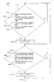
- FIG. 2 is a flowchart of an exemplary stop-start control method.
- FIG. 3 is a flowchart of an exemplary engine turn-on sequence.
- FIG. 4 is a flow chart an exemplary engine turnoff sequence.
- FIG. 5 is a flow chart of an exemplary engine turnoff sequence when the vehicle is traveling downhill.
- FIG. 6 is a block diagram illustrating an exemplary computer as may be used in connection with the systems to carry out the methods described herein.
- An engine 120 can be turned off because both the high voltage requirements and the low voltage requirements are met by respective energy storages 130 , 140 .
- a generator 150 is operated as a motor to spin the engine 120 during frequent restarts.
- a low-voltage engine starter 160 may be used infrequently to spin the engine 120 whenever the high-voltage energy storage 130 can not deliver enough power to the generator 150 for spinning the engine 120 during engine start.
- the low voltage starter 160 is used at the beginning of the day when the ultracapacitors are empty.
- the engine 120 may be any internal combustion engine that would be used to produce enough power to provide traction for propelling the vehicle.
- FIG. 1B an embodiment of a parallel hybrid-electric drive system 200 with electrically powered accessories 110 will be described.
- the engine 120 can be turned off because both the high voltage requirements and the low voltage requirements are met by the respective energy storages 130 , 140 .
- FIG. 1B illustrates that the electric motor mechanical output and the engine mechanical output operate in parallel and are coupled together to add power and torque to traction propulsion drive train 210 .
- a motor 220 is located in front or behind a transmission 230 and turns the same mechanical torque shaft as the engine and transmission.
- the engine 120 and the electric motor 220 must be able to decouple from the vehicle propulsion drive train 210 to allow the electric motor 220 to spin the engine 120 during engine startup.
- a separate generator/starter 240 capable of hundreds of restarts per day is provided for the engine 120 .
- an air conditioning (A/C) compressor 250 is assumed to include its own electric motor drive 260 similar to the air conditioning units used in fixed buildings.
- the hydraulic pump and air compressor units 270 , 280 are driven by the single electric motor 260 , but in an alternative embodiment, each may have its own electric motor.
- the low-voltage requirements are supplied by either a Power Take-Off (PTO) alternator or generator 270 , or a DC-to-DC converter 280 from the high voltage distribution buss.
- PTO Power Take-Off
- the low-voltage energy storage 140 is also shown in the diagrams, but may be unnecessary if the DC-to-DC converter 280 were used and there was always sufficient energy available to start the engine 120 .
- Stop-Start or Idle-Stop method 300 will be described.
- the method is embodied in the programmed software of the vehicle drive system control computer, which has the physical and protocol interfaces with the vehicle control and various component computers that control and report subsystem status.
- the software controls operation of the engine, generator, energy storage, and the drive system computer controllers to safely and efficiently turn off the engine 120 when the vehicle stops and restart the engine 120 when the vehicle starts moving again; thus, imitating the clean and quiet operation of a heavy duty electric powered vehicle (e.g., trolley bus).
- a heavy duty electric powered vehicle e.g., trolley bus
- the method 300 may use time history information and route sensitive information from a vehicle location, and a route identification system that would allow the engine 120 to be turned off in noise-sensitive areas and during downhill travel when the engine 120 is not required.
- the engine 120 may use a “Jake” cylinder compression brake, the transmission may use a hydraulic compression “retarder”, or an engine-transmission combination of a Jake brake and retarder may provide deceleration assistance. Because of this deceleration assistance and the PTO's for the control accessories, the engine 120 is not turned off when traveling downhill. In a hybrid-electric vehicle with electrically driven accessories 110 the engine 120 can be turned off because the deceleration assistance is provided by the braking regeneration drag of the electric propulsion motor on the drive train and the braking regeneration may provide enough power to run all the electrically driven accessories.
- braking regeneration power can be dissipated by braking resistors and by using the generator 150 to spin the engine 120 against its own compression. Additionally, while the engine is spinning by means of the generator and not consuming fuel, the engine may power any PTO accessories such as a low voltage alternator.
- the Stop-Start control computer stops the engine 120 by commanding the engine control unit to turn off the injection signals to the fuel injectors.
- the engine 120 turns off by stopping the engine fuel supply. If the engine 120 was stopped by either turning off the ignition or stopping the air intake there is a possibility of damaging the engine 120 during turn on because of a build up of unburned fuel in one or more of the engine cylinders.
- the Stop-Start method 300 the ignition and air intake are left on.
- the restart thresholds are significantly below the operating thresholds so as to prevent an oscillation of the Stop-Start cycles.
- the “start engine” vehicle speed threshold is set far enough above the “stop engine” vehicle speed threshold to prevent Stop-Start cycle oscillation during normal operation of the vehicle.
- the method 300 may use time history information and route sensitive information from a vehicle location, and a route identification system that would allow the engine to remain off in noise-sensitive areas and during downhill travel when the engine is not required. If any of these conditions 380 , 390 , 400 are met, at step 410 , the engine 120 is turned on and control returns to step 310 .
- step 430 is to turn on the fuel system by commanding the engine control unit to restore the signals to the fuel injectors.
- the generator In a series hybrid the generator is switched to a motor and draws power from the high voltage system to rotate the engine at an rpm above the engine idle rpm. In a parallel hybrid this function is performed by decoupling the motor from the drive train or by using a separate starter.
- Some modern engines have a heavy-duty low voltage alternator/generator that may function for this purpose if it is suitable to sustain the hundred of starts that may be required per day.
- the Stop-Start or Idle-Stop control computer monitors the power required by the generator to keep the engine 120 spinning.
- the engine state at step 460 , is defined as running and, at step 470 , the Stop-Start or Idle-Stop control computer commands the generator inverter/controller to switch from the motor mode (power negative) back into the generator mode (power positive).
- the Stop-Start or Idle-Stop control computer commands the generator inverter/controller to switch from the motor mode (power negative) back into the generator mode (power positive).
- the engine spinning is stopped after a maximum allowed spin time and a fault code is set.
- one or both of the systems 100 , 200 may include one or more the following: the software resides in an STW hybrid vehicle controller that uses an SAE J1939 “CAN” control area network to interface to the electric energy storage; the systems 100 , 200 include Siemens “ELFA” electric drive components including the generator, DUO-Inverter/controller, and electric propulsion motor; and other vehicle sensors and actuators; the speed is determined by reading the electric motor rpm through the motor controller; the low voltage SOC is determined from an analog to digital sensor that reads the battery voltage; the high voltage SOC is determined from the energy storage controller; the energy storage can be ultracapacitors, batteries, flywheels, or other device that stores and supplies electrical energy; the generator rpm and power level is obtained and controlled through the generator inverter/controller; the engine rpm can also be obtained from either the generator controller or the engine electronic control unit; and control of the engine 120 is performed through the CAN interface to the engine control unit.
- the software resides in an STW hybrid vehicle controller that uses an SAE J1939
- an exemplary engine turnoff or shutdown sequence 360 includes, at step 361 , turning off the fuel injectors supply of fuel to the engine.
- the fuel pump is not turned off so as to provide the fuel pressure as will be required for engine restart.
- the emissions control systems are turned off.
- the generator is switched to motor mode to spin the engine to clear any remaining fuel and send the exhaust products to the exhaust after treatment.
- the generator is commended to spin the engine at an rpm above idle to clear any remaining fuel.
- spark generation is turned off at step 365 , if necessary for engine control operation.
- the generator can be commanded to continue to spin the engine to run any PTO accessory devices with out consuming engine fuel. Such an operation is useful for slowing a vehicle during downhill travel as described by the flow diagram sequence in FIG. 5 below. Braking regeneration puts a drag on the vehicle drive line while providing power for the generator to spin the engine. The generator works against the engine compression and the power required by the PTO devices.
- an exemplary downhill engine turnoff sequence 600 includes, at step 610 , first determining if the vehicle is traveling downhill for a vehicle location and direction of travel along with topographic information, route information, and/or vehicle attitude information. If it is determined that the vehicle is traveling downhill, at step 350 , the engine is turned off as described by the flow diagram in FIG. 4 . Typically, at this point and not shown, the propulsion motor switches from motor mode to generator mode. At step 666 , the generator switches to motor mode to spin the engine. This operation continues until the vehicle is no longer traveling downhill as determined in step 670 . Finally, normal operation is resumed at step 410 where the engine restart sequence is initiated.
- FIG. 6 is a block diagram illustrating an exemplary computer 500 as may be used in connection with the systems 100 , 200 to carry out the above-described methods 300 , 410 , 360 , 600 and other functions.
- the computer 500 may be a digital control computer that has the physical and protocol interfaces with the vehicle control and various component computers that control and report subsystem status.
- other computers and/or architectures may be used, as will be clear to those skilled in the art.
- the computer 500 preferably includes one or more processors, such as processor 552 .
- Additional processors may be provided, such as an auxiliary processor to manage input/output, an auxiliary processor to perform floating point mathematical operations, a special-purpose microprocessor having an architecture suitable for fast execution of signal processing algorithms (e.g., digital signal processor), a slave processor subordinate to the main processing system (e.g., back-end processor), an additional microprocessor or controller for dual or multiple processor systems, or a coprocessor.
- auxiliary processors may be discrete processors or may be integrated with the processor 552 .
- the processor 552 is preferably connected to a communication bus 554 .
- the communication bus 554 may include a data channel for facilitating information transfer between storage and other peripheral components of the computer 500 .
- the communication bus 554 further may provide a set of signals used for communication with the processor 552 , including a data bus, address bus, and control bus (not shown).
- the communication bus 554 may comprise any standard or non-standard bus architecture such as, for example, bus architectures compliant with industry standard architecture (“ISA”), extended industry standard architecture (“EISA”), Micro Channel Architecture (“MCA”), peripheral component interconnect (“PCI”) local bus, or standards promulgated by the Institute of Electrical and Electronics Engineers (“IEEE”) including IEEE 488 general-purpose interface bus (“GPIB”), IEEE 696/S-100, and the like.
- ISA industry standard architecture
- EISA extended industry standard architecture
- MCA Micro Channel Architecture
- PCI peripheral component interconnect
- IEEE Institute of Electrical and Electronics Engineers
- IEEE Institute of Electrical and Electronics Engineers
- GPIB general-purpose interface bus
- IEEE 696/S-100 IEEE 696/S-100
- Computer 500 preferably includes a main memory 556 and may also include a secondary memory 558 .
- the main memory 556 provides storage of instructions and data for programs executing on the processor 552 .
- the main memory 556 is typically semiconductor-based memory such as dynamic random access memory (“DRAM”) and/or static random access memory (“SRAM”).
- DRAM dynamic random access memory
- SRAM static random access memory
- Other semiconductor-based memory types include, for example, synchronous dynamic random access memory (“SDRAM”), Rambus dynamic random access memory (“RDRAM”), ferroelectric random access memory (“FRAM”), and the like, including read only memory (“ROM”).
- SDRAM synchronous dynamic random access memory
- RDRAM Rambus dynamic random access memory
- FRAM ferroelectric random access memory
- ROM read only memory
- the secondary memory 558 may optionally include a hard disk drive 560 and/or a removable storage drive 562 , for example a floppy disk drive, a magnetic tape drive, a compact disc (“CD”) drive, a digital versatile disc (“DVD”) drive, etc.
- the removable storage drive 562 reads from and/or writes to a removable storage medium or removable memory device 564 in a well-known manner.
- Removable storage medium 564 may be, for example, a floppy disk, magnetic tape, CD, DVD, etc.
- the removable storage medium 564 is preferably a computer readable medium having stored thereon computer executable code (i.e., software) and/or data.
- the computer software or data stored on the removable storage medium 564 is read into the computer 500 as electrical communication signals 578 .
- secondary memory 558 may include other similar means for allowing computer programs or other data or instructions to be loaded into the computer 500 .
- Such means may include, for example, an external storage medium 572 and an interface 570 .
- external storage medium 572 may include an external hard disk drive or an external optical drive, or and external magneto-optical drive.
- secondary memory 558 may include semiconductor-based memory such as programmable read-only memory (“PROM”), erasable programmable read-only memory (“EPROM”), electrically erasable read-only memory (“EEPROM”), or flash memory (block oriented memory similar to EEPROM). Also included are any other removable storage units 572 and interfaces 570 , which allow software and data to be transferred from the removable storage unit 572 to the computer 500 .
- PROM programmable read-only memory
- EPROM erasable programmable read-only memory
- EEPROM electrically erasable read-only memory
- flash memory block oriented memory similar to EEPROM
- Computer 500 may also include a communication interface 574 .
- the communication interface 574 allows software and data to be transferred between computer 500 and external devices (e.g. printers), networks, or information sources.
- external devices e.g. printers
- computer software or executable code may be transferred to computer 500 from a network server via communication interface 574 .
- Examples of communication interface 574 include a modem, a network interface card (“NIC”), a communications port, a PCMCIA slot and card, an infrared interface, and an IEEE 1394 fire-wire, just to name a few.
- Communication interface 574 preferably implements industry promulgated protocol standards, such as Ethernet IEEE 802 standards, Fiber Channel, digital subscriber line (“DSL”), asynchronous digital subscriber line (“ADSL”), frame relay, asynchronous transfer mode (“ATM”), integrated digital services network (“ISDN”), personal communications services (“PCS”), transmission control protocol/internet protocol (“TCP/IP”), serial line internet protocol/point to point protocol (“SLIP/PPP”), and so on, but may also implement customized or non-standard interface protocols as well.
- industry promulgated protocol standards such as Ethernet IEEE 802 standards, Fiber Channel, digital subscriber line (“DSL”), asynchronous digital subscriber line (“ADSL”), frame relay, asynchronous transfer mode (“ATM”), integrated digital services network (“ISDN”), personal communications services (“PCS”), transmission control protocol/internet protocol (“TCP/IP”), serial line internet protocol/point to point protocol (“SLIP/PPP”), and so on, but may also implement customized or non-standard interface protocols as well.
- Communication interface 574 Software and data transferred via communication interface 574 are generally in the form of electrical communication signals 578 . These signals 578 are preferably provided to communication interface 574 via a communication channel 576 .
- Communication channel 576 carries signals 578 and can be implemented using a variety of communication means including wire or cable, fiber optics, conventional phone line, cellular phone link, radio frequency (RF) link, or infrared link, just to name a few.
- RF radio frequency
- Computer executable code i.e., computer programs or software
- main memory 556 and/or the secondary memory 558 Computer programs can also be received via communication interface 574 and stored in the main memory 556 and/or the secondary memory 558 . Such computer programs, when executed, enable the computer 500 to perform the various functions of the present invention as previously described.
- computer readable medium is used to refer to any media used to provide computer executable code (e.g., software and computer programs) to the computer 500 .
- Examples of these media include main memory 556 , secondary memory 558 (including hard disk drive 560 , removable storage medium 564 , and external storage medium 572 ), and any peripheral device communicatively coupled with communication interface 574 (including a network information server or other network device).
- These computer readable mediums are means for providing executable code, programming instructions, and software to the computer 500 .
- the software may be stored on a computer readable medium and loaded into computer 500 by way of removable storage drive 562 , interface 570 , or communication interface 574 .
- the software is loaded into the computer 500 in the form of electrical communication signals 578 .
- the software when executed by the processor 552 , preferably causes the processor 552 to perform the inventive features and functions previously described herein.
- ASICs application specific integrated circuits
- FPGAs field programmable gate arrays
- ASICs application specific integrated circuits
- FPGAs field programmable gate arrays
Abstract
Description
Claims (24)
Priority Applications (1)
| Application Number | Priority Date | Filing Date | Title |
|---|---|---|---|
| US11/948,760 US7657350B2 (en) | 2004-12-01 | 2007-11-30 | Method of controlling engine stop-start operation for heavy-duty hybrid-electric and hybrid-hydraulic vehicles |
Applications Claiming Priority (3)
| Application Number | Priority Date | Filing Date | Title |
|---|---|---|---|
| US63204604P | 2004-12-01 | 2004-12-01 | |
| US11/289,069 US7689330B2 (en) | 2004-12-01 | 2005-11-29 | Method of controlling engine stop-start operation for heavy-duty hybrid-electric and hybrid-hydraulic vehicles |
| US11/948,760 US7657350B2 (en) | 2004-12-01 | 2007-11-30 | Method of controlling engine stop-start operation for heavy-duty hybrid-electric and hybrid-hydraulic vehicles |
Related Parent Applications (1)
| Application Number | Title | Priority Date | Filing Date |
|---|---|---|---|
| US11/289,069 Division US7689330B2 (en) | 2004-12-01 | 2005-11-29 | Method of controlling engine stop-start operation for heavy-duty hybrid-electric and hybrid-hydraulic vehicles |
Publications (2)
| Publication Number | Publication Date |
|---|---|
| US20080097661A1 US20080097661A1 (en) | 2008-04-24 |
| US7657350B2 true US7657350B2 (en) | 2010-02-02 |
Family
ID=36568310
Family Applications (2)
| Application Number | Title | Priority Date | Filing Date |
|---|---|---|---|
| US11/289,069 Expired - Fee Related US7689330B2 (en) | 2004-12-01 | 2005-11-29 | Method of controlling engine stop-start operation for heavy-duty hybrid-electric and hybrid-hydraulic vehicles |
| US11/948,760 Expired - Fee Related US7657350B2 (en) | 2004-12-01 | 2007-11-30 | Method of controlling engine stop-start operation for heavy-duty hybrid-electric and hybrid-hydraulic vehicles |
Family Applications Before (1)
| Application Number | Title | Priority Date | Filing Date |
|---|---|---|---|
| US11/289,069 Expired - Fee Related US7689330B2 (en) | 2004-12-01 | 2005-11-29 | Method of controlling engine stop-start operation for heavy-duty hybrid-electric and hybrid-hydraulic vehicles |
Country Status (1)
| Country | Link |
|---|---|
| US (2) | US7689330B2 (en) |
Cited By (44)
| Publication number | Priority date | Publication date | Assignee | Title |
|---|---|---|---|---|
| US20090018716A1 (en) * | 2007-07-12 | 2009-01-15 | Joseph Mario Ambrosio | Parallel hybrid drive system utilizing power take off connection as transfer for a secondary energy source |
| US20090095549A1 (en) * | 2007-10-12 | 2009-04-16 | Joseph Thomas Dalum | Hybrid vehicle drive system and method and idle reduction system and method |
| US20090236156A1 (en) * | 2008-03-20 | 2009-09-24 | Terex-Telelect, Inc. | Hybrid drive for hydraulic power |
| US20100219007A1 (en) * | 2007-07-12 | 2010-09-02 | Odyne Systems, Llc | Hybrid vehicle drive system and method and idle reduction system and method |
| US20130032429A1 (en) * | 2010-03-25 | 2013-02-07 | Marco Aimo Boot | Power steering system for a vehicle provided with means for actuating the stop & start function in a moving vehicle, especially an industrial or commercial or special vehicle |
| US20130056279A1 (en) * | 2010-05-25 | 2013-03-07 | Sandvik Mining And Construction Oy | Rock drilling rig and method for downhill drive |
| US20130286789A1 (en) * | 2012-04-30 | 2013-10-31 | Conocophillips Company | Active isolation apparatus |
| US20130286791A1 (en) * | 2012-04-30 | 2013-10-31 | Conocophillips Company | Discrete electric seismic source unit |
| US20130286771A1 (en) * | 2012-04-30 | 2013-10-31 | Conocophillips Company | Alternative vibrator actuator source |
| US20130286779A1 (en) * | 2012-04-30 | 2013-10-31 | Conocophillips Company | Quasi-impulsive displacement source |
| US20130286790A1 (en) * | 2012-04-30 | 2013-10-31 | Conocophillips Company | Simultaneous composite land seismic sweep |
| US20130286788A1 (en) * | 2012-04-30 | 2013-10-31 | Conocophillips Company | Electrical energy accumulator |
| US20130308422A1 (en) * | 2012-04-30 | 2013-11-21 | Conocophillips Company | Constant energy displacements |
| US20130328393A1 (en) * | 2010-11-02 | 2013-12-12 | Transport Energy Systems Pty Ltd. | Ac drive system for a vehicle |
| US20140088810A1 (en) * | 2011-04-27 | 2014-03-27 | Daimler Ag | Hybrid Drive Control Device |
| US20140257637A1 (en) * | 2013-03-11 | 2014-09-11 | Ford Global Technologies, Llc | Control for stop/start vehicle when approaching controlled intersections |
| US9061680B2 (en) | 2007-07-12 | 2015-06-23 | Odyne Systems, Llc | Hybrid vehicle drive system and method for fuel reduction during idle |
| US9102334B2 (en) | 2012-10-29 | 2015-08-11 | Deere & Company | Methods and apparatus to control motors |
| US9174525B2 (en) | 2013-02-25 | 2015-11-03 | Fairfield Manufacturing Company, Inc. | Hybrid electric vehicle |
| US9217799B2 (en) * | 2012-04-30 | 2015-12-22 | Conocophillips Company | Distinctive land seismic sweep |
| US9283954B2 (en) | 2007-07-12 | 2016-03-15 | Odyne Systems, Llc | System for and method of fuel optimization in a hybrid vehicle |
| US9296385B2 (en) | 2013-03-14 | 2016-03-29 | Allison Transmission, Inc. | System and method for power management during regeneration mode in hybrid electric vehicles for H-3000 |
| US9555800B2 (en) | 2013-03-15 | 2017-01-31 | Allison Transmission, Inc. | Service disconnect interlock system and method for hybrid vehicles |
| US9555719B2 (en) | 2013-03-14 | 2017-01-31 | Allison Transmission, Inc. | System and method for optimizing hybrid vehicle battery usage constraints |
| US9592822B2 (en) | 2013-03-15 | 2017-03-14 | Allison Transmission, Inc. | System and method for energy rate balancing in hybrid automatic transmissions |
| US9651144B2 (en) | 2012-10-31 | 2017-05-16 | Allison Transmission, Inc. | Method of controlling a hydraulic pressurization system of a transmission |
| US9701312B2 (en) | 2013-12-11 | 2017-07-11 | Caterpillar Inc. | Idle reduction engine shutdown and restart system for a machine |
| US9714021B2 (en) | 2013-03-14 | 2017-07-25 | Allison Transmission, Inc. | System and method for compensation of turbo lag in hybrid vehicles |
| US9738272B2 (en) | 2013-03-14 | 2017-08-22 | Allison Transmission, Inc. | System and method for engine driveline disconnect during regeneration in hybrid vehicles |
| US9745940B2 (en) | 2014-02-28 | 2017-08-29 | Caterpillar Inc. | Machine having hydraulic start assist system |
| US9878616B2 (en) | 2007-07-12 | 2018-01-30 | Power Technology Holdings Llc | Hybrid vehicle drive system and method using split shaft power take off |
| US9932029B2 (en) | 2013-03-15 | 2018-04-03 | Allison Transmission, Inc. | System and method for balancing states of charge of energy storage modules in hybrid vehicles |
| US10343679B2 (en) * | 2017-08-10 | 2019-07-09 | Toyota Jidosha Kabushiki Kaisha | Hybrid vehicle and control method of hybrid vehicle |
| US10427520B2 (en) | 2013-11-18 | 2019-10-01 | Power Technology Holdings Llc | Hybrid vehicle drive system and method using split shaft power take off |
| US10436167B1 (en) * | 2018-04-24 | 2019-10-08 | GM Global Technology Operations LLC | Starter system and method of control |
| US10487762B2 (en) | 2017-09-26 | 2019-11-26 | Paccar Inc | Systems and methods for predictive and automatic engine stop-start control |
| US10605217B2 (en) | 2017-03-07 | 2020-03-31 | GM Global Technology Operations LLC | Vehicle engine starter control systems and methods |
| US10690103B2 (en) | 2017-09-26 | 2020-06-23 | Paccar Inc | Systems and methods for using an electric motor in predictive and automatic engine stop-start systems |
| US10703210B2 (en) * | 2013-11-26 | 2020-07-07 | Ford Global Technologies, Llc | Method of controlling a mild hybrid electric vehicle |
| US10746255B2 (en) | 2018-05-09 | 2020-08-18 | Paccar Inc | Systems and methods for reducing noise, vibration, and/or harshness during engine shutdown and restart |
| US10883566B2 (en) | 2018-05-09 | 2021-01-05 | Paccar Inc | Systems and methods for reducing noise, vibration and/or harshness associated with cylinder deactivation in internal combustion engines |
| US10934988B2 (en) | 2016-11-02 | 2021-03-02 | Paccar Inc | Intermittent restart for automatic engine stop start system |
| US11225240B2 (en) | 2011-12-02 | 2022-01-18 | Power Technology Holdings, Llc | Hybrid vehicle drive system and method for fuel reduction during idle |
| US11584242B2 (en) | 2007-07-12 | 2023-02-21 | Power Technology Holdings Llc | Hybrid vehicle drive system and method and idle reduction system and method |
Families Citing this family (80)
| Publication number | Priority date | Publication date | Assignee | Title |
|---|---|---|---|---|
| JP3818278B2 (en) * | 2003-07-22 | 2006-09-06 | トヨタ自動車株式会社 | Hybrid vehicle and control method thereof |
| US7427156B2 (en) * | 2004-12-20 | 2008-09-23 | Odyne Corporation | Thermally managed battery enclosure for electric and hybrid electric vehicles |
| CA2531295C (en) * | 2004-12-22 | 2013-10-22 | Odyne Corporation | Battery management and equalization system for batteries using power line carrier communications |
| ITBO20040801A1 (en) * | 2004-12-23 | 2005-03-23 | Magneti Marelli Powertrain Spa | METHOD FOR THE MANAGEMENT OF THE "STOP AND START" MODE IN A MOTOR VEHICLE PROVIDED WITH AN INTERNAL COMBUSTION ENGINE. |
| US7830117B2 (en) | 2005-01-10 | 2010-11-09 | Odyne Systems, Llc | Vehicle charging, monitoring and control systems for electric and hybrid electric vehicles |
| FR2882700B1 (en) * | 2005-03-01 | 2008-10-31 | Peugeot Citroen Automobiles Sa | METHOD FOR TRANSMITTING POWER BETWEEN A HEAT ENGINE AND WHEELS OF A MOTOR VEHICLE AND ASSOCIATED DEVICE |
| FR2882697B1 (en) * | 2005-03-01 | 2008-10-31 | Peugeot Citroen Automobiles Sa | METHOD FOR CHANGING SPEED RATIO |
| DE102006008759B4 (en) * | 2006-02-24 | 2021-09-30 | Borgwarner Ludwigsburg Gmbh | Diesel engine for vehicles |
| DE102006027387B4 (en) * | 2006-06-13 | 2011-01-27 | Continental Automotive Gmbh | Brake system for a hybrid motor vehicle, associated method for their functional integrity and associated control unit |
| JP4780402B2 (en) * | 2006-06-27 | 2011-09-28 | 株式会社デンソー | Vehicle power supply |
| DE202006019422U1 (en) * | 2006-11-06 | 2008-04-10 | Faun Umwelttechnik Gmbh & Co. Kg | hybrid drive |
| FR2908477B1 (en) * | 2006-11-15 | 2009-01-16 | Peugeot Citroen Automobiles Sa | METHOD FOR CONTROLLING A DEVICE FOR AUTOMATICALLY STOPPING AND RESTARTING A THERMAL MOTOR |
| JP4417948B2 (en) * | 2006-11-24 | 2010-02-17 | 株式会社日立製作所 | Railway vehicle drive control device |
| JP2008151064A (en) * | 2006-12-19 | 2008-07-03 | Toyota Motor Corp | Control device for internal combustion engine |
| WO2008103174A1 (en) * | 2007-02-22 | 2008-08-28 | Mack Trucks, Inc. | Hybrid vehicle auxiliary equipment energy management |
| US8234031B2 (en) * | 2007-02-22 | 2012-07-31 | Mack Trucks, Inc. | Hybrid vehicle energy management methods and apparatus |
| CA2680889A1 (en) * | 2007-03-20 | 2008-09-25 | Litens Automotive Partnership | Starter and accessory drive system and method for hybrid drive vehicles |
| DE102007035824A1 (en) * | 2007-07-31 | 2009-02-05 | Robert Bosch Gmbh | Pressure maintenance function with full hybrid drive |
| FR2919544B1 (en) * | 2007-08-03 | 2009-10-30 | Christophe Gaussin | AUTOMOTIVE VEHICLE CLEAN OF HEAVY TRANSPORT, IN PARTICULAR PORT |
| FR2921884A1 (en) * | 2007-10-03 | 2009-04-10 | Peugeot Citroen Automobiles Sa | METHOD FOR CONTROLLING A HYBRID TRACTION CHAIN BASED ON THE BATTERY CHARGE STATE |
| AU2009206423B2 (en) * | 2008-01-23 | 2012-09-20 | Parker-Hannifin Corporation | Electro-hydraulic machine for hybri drive system |
| TW201000340A (en) * | 2008-06-20 | 2010-01-01 | Sunyen Co Ltd | Driving auxiliary system of power steering wheel |
| FR2933357B1 (en) * | 2008-07-02 | 2011-02-11 | Peugeot Citroen Automobiles Sa | MULTI VOLTAGE ELECTRICAL MANAGEMENT SYSTEM FOR A HYBRID VEHICLE. |
| US8073605B2 (en) * | 2008-08-13 | 2011-12-06 | GM Global Technology Operations LLC | Method of managing power flow in a vehicle |
| JP4609567B2 (en) * | 2008-10-29 | 2011-01-12 | コベルコ建機株式会社 | Hybrid work machine |
| US20100117594A1 (en) * | 2008-11-13 | 2010-05-13 | International Truck Intellectual Property Company, Llc | Strategy for maintaining state of charge of a low-voltage battery bank in a hybrid electric vehicle having a high-voltage traction battery bank |
| JP5149826B2 (en) * | 2009-01-29 | 2013-02-20 | 住友重機械工業株式会社 | Hybrid work machine and servo control system |
| DE102010025335A1 (en) * | 2009-07-27 | 2011-02-03 | Luk Lamellen Und Kupplungsbau Beteiligungs Kg | Method for controlling a hybrid vehicle |
| WO2011056642A2 (en) * | 2009-10-27 | 2011-05-12 | Carrier Corporation | Hybrid refrigeration system for a mobile unit and method of operation |
| US8770327B2 (en) * | 2009-12-18 | 2014-07-08 | Ud Trucks Corporation | Accessory drive mechanism for hybrid vehicle |
| DE102010005022A1 (en) * | 2010-01-19 | 2011-07-21 | Continental Automotive GmbH, 30165 | Vehicle with electric drive |
| WO2011133154A1 (en) * | 2010-04-22 | 2011-10-27 | International Engine Intellectual Property Company, Llc | Method of controlling engine shut down |
| DE102010039800A1 (en) * | 2010-08-26 | 2012-03-01 | Robert Bosch Gmbh | Method and device for detecting the autonomous running of an internal combustion engine |
| US8746382B2 (en) * | 2010-12-23 | 2014-06-10 | Caterpillar Inc. | Switched reluctance generator priming strategy |
| US9043065B2 (en) * | 2010-12-23 | 2015-05-26 | Siemens S.A.S. | Method of adjusting the electrical supply voltage for the operation of at least one electrically powered vehicle |
| US8497591B2 (en) * | 2010-12-29 | 2013-07-30 | General Electric Company | System and method for off-highway vehicle engine cranking |
| EP2471679A3 (en) | 2010-12-29 | 2016-07-20 | Parker-Hannificn Corporation | Apparatus and method for operating a hybrid drive system during an extended braking condition |
| DE112011104804T5 (en) * | 2011-01-31 | 2013-10-31 | Suzuki Motor Corporation | hybrid vehicle |
| US10536007B2 (en) | 2011-03-05 | 2020-01-14 | Powin Energy Corporation | Battery energy storage system and control system and applications thereof |
| US9847654B2 (en) | 2011-03-05 | 2017-12-19 | Powin Energy Corporation | Battery energy storage system and control system and applications thereof |
| FR2977198B1 (en) | 2011-06-28 | 2013-08-09 | Renault Sa | ELECTRIC HYBRID VEHICLE ARCHITECTURE, HYBRID VEHICLE AND CONTROL METHOD |
| US10480477B2 (en) * | 2011-07-11 | 2019-11-19 | Ford Global Technologies, Llc | Electric current based engine auto stop inhibit algorithm and system implementing same |
| US9447765B2 (en) | 2011-07-11 | 2016-09-20 | Ford Global Technologies, Llc | Powertrain delta current estimation method |
| DE102011111924B4 (en) * | 2011-08-31 | 2019-10-31 | Atlas Weyhausen Gmbh | Construction machine, in particular wheel loader or roller |
| CN104411557B (en) * | 2011-10-21 | 2018-06-22 | 凯莱汽车公司 | For controlling the system and method for the operation of vehicle |
| EP2799833B1 (en) * | 2011-12-28 | 2019-12-04 | Honda Motor Co., Ltd. | Vehicle diagnostic system, vehicle diagnostic method, and external diagnostic device |
| AU2013209246B2 (en) | 2012-01-11 | 2016-08-11 | 14156048 Canada Inc. | Fuel saving system that facilitates vehicle re-starts with the engine off |
| FR2995466B1 (en) * | 2012-09-13 | 2014-08-29 | Renault Sa | SYSTEM AND METHOD FOR MANAGING THE POWER SUPPLY OF AT LEAST ONE AUTOMATIC RESTART EQUIPMENT OF A VEHICLE HEAT ENGINE |
| US9145863B2 (en) * | 2013-03-15 | 2015-09-29 | General Electric Company | System and method for controlling automatic shut-off of an engine |
| US9407194B2 (en) | 2013-03-15 | 2016-08-02 | Emerson Climate Technologies, Inc. | System and method for protection of a compressor with an aluminum winding motor |
| CN104052199B (en) * | 2013-03-15 | 2017-09-08 | 艾默生环境优化技术有限公司 | Compressor, the method and apparatus for protecting compressor |
| DE102013008420A1 (en) * | 2013-05-17 | 2014-11-20 | Abb Technology Ag | Drive unit for controlling a motor |
| GB2519158A (en) * | 2013-10-14 | 2015-04-15 | Gm Global Tech Operations Inc | Method of controlling an automatic engine stop during coasting phase |
| US9035481B1 (en) * | 2013-12-09 | 2015-05-19 | Textron Inc. | Using AC and DC generators with controllers as a regenerative power burn off device |
| US9272628B2 (en) | 2013-12-09 | 2016-03-01 | Textron Inc. | Using AC induction motor as a generator in a utility vehicle |
| US9168836B2 (en) * | 2013-12-13 | 2015-10-27 | Powin Energy Corporation | Non-traction battery controller and applications thereof |
| US9677529B2 (en) | 2013-12-25 | 2017-06-13 | Denso Corporation | Vehicle diagnosis system and method |
| CN104029590B (en) * | 2014-04-28 | 2017-02-08 | 河南科技大学 | Tractor driven by tandem type hybrid power and control method thereof |
| US10263436B2 (en) | 2014-10-20 | 2019-04-16 | Powin Energy Corporation | Electrical energy storage unit and control system and applications thereof |
| US9586485B2 (en) | 2015-03-23 | 2017-03-07 | Ford Global Technologies, Llc | Electrified vehicle energy dissipation |
| CN106374549B (en) * | 2015-07-23 | 2019-05-17 | 比亚迪股份有限公司 | The charging system of automobile batteries and the charging method of automobile batteries and automobile |
| US10153521B2 (en) | 2015-08-06 | 2018-12-11 | Powin Energy Corporation | Systems and methods for detecting a battery pack having an operating issue or defect |
| US10254350B2 (en) | 2015-08-06 | 2019-04-09 | Powin Energy Corporation | Warranty tracker for a battery pack |
| US10122186B2 (en) | 2015-09-11 | 2018-11-06 | Powin Energy Corporation | Battery management systems (BMS) having isolated, distributed, daisy-chained battery module controllers |
| US9923247B2 (en) | 2015-09-11 | 2018-03-20 | Powin Energy Corporation | Battery pack with integrated battery management system |
| US10040363B2 (en) | 2015-10-15 | 2018-08-07 | Powin Energy Corporation | Battery-assisted electric vehicle charging system and method |
| US9816474B2 (en) | 2015-10-20 | 2017-11-14 | Ford Global Technologies, Llc | State of charge based engine start-stop control |
| US9882401B2 (en) | 2015-11-04 | 2018-01-30 | Powin Energy Corporation | Battery energy storage system |
| GB2547959B (en) * | 2016-01-08 | 2020-07-08 | Cummins Inc | Communication interface for start-stop systems and methods |
| CN107839468B (en) * | 2016-01-21 | 2019-12-10 | 厦门市福工动力技术有限公司 | hybrid power system with high charge-discharge efficiency and control method thereof |
| CA3014501C (en) | 2016-02-16 | 2024-03-12 | Developpement Effenco Inc. | Expanded functionality stop-start fuel saving system for vocational vehicles |
| US11220160B2 (en) * | 2016-09-09 | 2022-01-11 | Terex Usa, Llc | System and method for idle mitigation on a utility truck with an electrically isolated hydraulically controlled aerial work platform |
| US10699278B2 (en) | 2016-12-22 | 2020-06-30 | Powin Energy Corporation | Battery pack monitoring and warranty tracking system |
| EP3595952B1 (en) * | 2017-03-17 | 2022-01-12 | Cummins Inc. | Controlling a vehicle equipped with engine start-stop control logic in response to vehicle stop event type |
| JP6648732B2 (en) * | 2017-05-25 | 2020-02-14 | トヨタ自動車株式会社 | Vehicle control device |
| US10439427B2 (en) * | 2017-08-03 | 2019-10-08 | Ford Global Technologies, Llc | Determining a fuel quantity to charge a vehicle battery |
| US20190351895A1 (en) * | 2019-04-30 | 2019-11-21 | Jacob Ben-Ari | INTEGRATED PROPULSION & STEERING For Battery Electric Vehicles (BEV), Hybrid Electric Vehicles (HEV), Fuel Cell Electric Vehicles (FCEV), AV (Autonomous Vehicles); Electric Trucks, Buses and Semi-Trailers |
| JP7351175B2 (en) | 2019-10-09 | 2023-09-27 | 日産自動車株式会社 | Hybrid vehicle charging control method and hybrid vehicle charging control device |
| GB2592237B (en) * | 2020-02-20 | 2022-07-20 | Terex Gb Ltd | Material processing apparatus with hybrid power system |
| EP4194248A1 (en) * | 2021-12-13 | 2023-06-14 | Volvo Truck Corporation | A braking system and method of controlling such a braking system |
Citations (59)
| Publication number | Priority date | Publication date | Assignee | Title |
|---|---|---|---|---|
| US3791473A (en) | 1972-09-21 | 1974-02-12 | Petro Electric Motors Ltd | Hybrid power train |
| US4113045A (en) * | 1977-02-16 | 1978-09-12 | Downing Jr James H | All-electric a.c. tractor |
| US4196587A (en) * | 1978-02-06 | 1980-04-08 | Samuel Shiber | Multi-mode transmission |
| US4282947A (en) * | 1978-05-11 | 1981-08-11 | Vadetec Corporation | Hybrid vehicular power system and method |
| US4533011A (en) * | 1979-10-27 | 1985-08-06 | Volkswagenwerk Aktiengesellschaft | Hybrid drive for a vehicle, in particular an automobile |
| US5081365A (en) * | 1990-06-06 | 1992-01-14 | Field Bruce F | Electric hybrid vehicle and method of controlling it |
| US5327992A (en) * | 1992-05-28 | 1994-07-12 | Mercedes-Benz Ag | Method for controlling a hybrid drive which drives a vehicle |
| US5343970A (en) | 1992-09-21 | 1994-09-06 | Severinsky Alex J | Hybrid electric vehicle |
| US5402046A (en) | 1992-07-01 | 1995-03-28 | Smh Management Services Ag | Vehicle drive system |
| US5568023A (en) | 1994-05-18 | 1996-10-22 | Grayer; William | Electric power train control |
| JPH08308020A (en) * | 1995-05-02 | 1996-11-22 | Hino Motors Ltd | Auxiliary acceleration and auxiliary brake unit |
| US5650713A (en) | 1994-07-01 | 1997-07-22 | Nippondenso Co., Ltd. | Control device for a hybrid automobile |
| US5669842A (en) * | 1996-04-29 | 1997-09-23 | General Motors Corporation | Hybrid power transmission with power take-off apparatus |
| US5698905A (en) | 1994-10-05 | 1997-12-16 | Fichtel & Sachs Ag | Hybrid propulsion system for a motor vehicle and a method of operating the hybrid propulsion system |
| US5713427A (en) * | 1994-02-08 | 1998-02-03 | Fichtel & Sachs Ag | Hybrid drive in a motor vehicle |
| US5788597A (en) | 1994-12-23 | 1998-08-04 | Mercedes-Benz Ag | Process and apparatus for braking a hybrid-drive motor vehicle |
| US5823280A (en) * | 1995-01-12 | 1998-10-20 | Nevcor, Inc. | Hybrid parallel electric vehicle |
| US5841201A (en) | 1996-02-29 | 1998-11-24 | Toyota Jidosha Kabushiki Kaisha | Hybrid vehicle drive system having a drive mode using both engine and electric motor |
| US5954779A (en) | 1996-12-06 | 1999-09-21 | Voith Turbo Gmbh & Co. Kg | Drag torque control method in a diesel electric drive system and drive system |
| US5996722A (en) | 1995-04-05 | 1999-12-07 | Price; Richard David | Vehicle steering systems |
| US6018694A (en) | 1996-07-30 | 2000-01-25 | Denso Corporation | Controller for hybrid vehicle |
| US6038500A (en) * | 1997-03-12 | 2000-03-14 | Deere & Company | Computer/bus message system for vehicle drive control system |
| US6098734A (en) | 1996-06-06 | 2000-08-08 | Isuzu Ceramics Research Institute Co., Ltd. | Hybrid powered automobile with controller |
| US6098733A (en) | 1995-10-13 | 2000-08-08 | Toyota Jidosha Kabushiki Kaisha | Hybrid drive system for motor vehicle |
| US6114775A (en) | 1997-10-27 | 2000-09-05 | Mando Machinery Corporation | Control system of auxiliary power system for a hybrid electric vehicle |
| US6131538A (en) | 1997-06-06 | 2000-10-17 | Toyota Jidosha Kabushiki Kaisha | Apparatus for controlling internal combustion engine in hybrid vehicle and method of the same |
| US6166449A (en) | 1996-09-17 | 2000-12-26 | Toyota Jidosha Kabushiki Kaisha | Power output apparatus having a battery with a high charge-discharge efficiency |
| US6170587B1 (en) | 1997-04-18 | 2001-01-09 | Transport Energy Systems Pty Ltd | Hybrid propulsion system for road vehicles |
| US6209672B1 (en) | 1998-09-14 | 2001-04-03 | Paice Corporation | Hybrid vehicle |
| US6213233B1 (en) | 1998-04-07 | 2001-04-10 | The Swatch Group Management Services Ag | System for cooling drive units and for heating the inner space of a hybrid vehicle |
| US20010039230A1 (en) | 1998-09-14 | 2001-11-08 | Severinsky Alex J. | Hybrid vehicles |
| US6323608B1 (en) | 2000-08-31 | 2001-11-27 | Honda Giken Kogyo Kabushiki Kaisha | Dual voltage battery for a motor vehicle |
| US6360834B1 (en) * | 2000-07-14 | 2002-03-26 | Ford Global Tech., Inc. | Hybrid electric vehicle |
| US6385529B1 (en) * | 1998-05-11 | 2002-05-07 | Hitachi, Ltd. | Vehicle and device and method for controlling running of the same |
| US20020069000A1 (en) | 2000-12-04 | 2002-06-06 | Yoshitada Nakao | Apparatus for controlling hybrid electric vehicle |
| US6406102B1 (en) | 1999-02-24 | 2002-06-18 | Orscheln Management Co. | Electrically operated parking brake control system |
| US20020096137A1 (en) * | 2001-01-19 | 2002-07-25 | Honda Giken Kogyo Kabushiki Kaisha | Control system and method for automatically stopping and starting vehicle engine |
| US6459980B1 (en) | 1999-02-08 | 2002-10-01 | Toyota Jidosha Kabushiki Kaisha | Vehicle braked with motor torque and method of controlling the same |
| US20020142884A1 (en) | 2001-03-28 | 2002-10-03 | Honda Giken Kogyo Kabushiki Kaisha | Control apparatus for hybrid vehicle |
| US20020143441A1 (en) * | 2001-03-30 | 2002-10-03 | Aisin Aw Co., Ltd. | Apparatus, method, and program for drivingly controlling hybrid vehicles |
| US6461266B1 (en) | 2001-04-26 | 2002-10-08 | Ervin Weisz | Differential electric engine with variable torque conversion |
| US6476571B1 (en) | 1999-03-11 | 2002-11-05 | Toyota Jidosha Kabushiki Kaisha | Multiple power source system and apparatus, motor driving apparatus, and hybrid vehicle with multiple power source system mounted thereon |
| US6481516B1 (en) * | 1992-05-08 | 2002-11-19 | Field Hybrids, Llc | Electric hybrid vehicle |
| US6483198B2 (en) | 2001-01-19 | 2002-11-19 | Transportation Techniques Llc | Hybrid electric vehicle having a selective zero emission mode, and method of selectively operating the zero emission mode |
| US6487477B1 (en) * | 2001-05-09 | 2002-11-26 | Ford Global Technologies, Inc. | Strategy to use an on-board navigation system for electric and hybrid electric vehicle energy management |
| US6484833B1 (en) * | 2000-03-17 | 2002-11-26 | General Motors Corporation | Apparatus and method for maintaining state of charge in vehicle operations |
| US6484831B1 (en) * | 2000-07-14 | 2002-11-26 | Ford Global Technologies, Inc. | Hybrid electric vehicle |
| US20030073540A1 (en) | 2001-10-17 | 2003-04-17 | Takahiro Eguchi | Vehicular power-transmission control system |
| US20030100395A1 (en) * | 2001-11-28 | 2003-05-29 | Kazuyoshi Hiraiwa | Powertrain for hybrid electric vehicles |
| US20030162631A1 (en) * | 2002-02-27 | 2003-08-28 | Williams Cameron P. | Hybrid vehicle system |
| US20030168263A1 (en) | 1999-04-19 | 2003-09-11 | Botti Jean Joseph | Power generation system and method |
| US6624527B1 (en) | 2000-09-15 | 2003-09-23 | Ford Motor Company | Method and apparatus for reducing engine cycling in hybrid electric vehicle |
| US6622804B2 (en) | 2001-01-19 | 2003-09-23 | Transportation Techniques, Llc. | Hybrid electric vehicle and method of selectively operating the hybrid electric vehicle |
| US6672415B1 (en) | 1999-05-26 | 2004-01-06 | Toyota Jidosha Kabushiki Kaisha | Moving object with fuel cells incorporated therein and method of controlling the same |
| US20040030469A1 (en) | 2002-08-06 | 2004-02-12 | Macbain John A. | Method and control system for controlling propulsion in a hybrid vehicle |
| US6700213B1 (en) | 1999-10-29 | 2004-03-02 | Honda Giken Kogyo Kabushiki Kaisha | Control system for a hybrid vehicle in which output from the engine is assisted by the motor based on air-fuel ratio determination |
| US6817329B2 (en) | 2002-11-12 | 2004-11-16 | Daimlerchrysler Corporation | Idle stop-start control method |
| US20050228553A1 (en) | 2004-03-30 | 2005-10-13 | Williams International Co., L.L.C. | Hybrid Electric Vehicle Energy Management System |
| US6961654B2 (en) | 2001-05-03 | 2005-11-01 | Ford Global Technologies, Llc | Controlled engine shutdown for a hybrid electric vehicle |
Family Cites Families (1)
| Publication number | Priority date | Publication date | Assignee | Title |
|---|---|---|---|---|
| JP2003118200A (en) * | 2001-10-16 | 2003-04-23 | Dainippon Printing Co Ltd | Method for preventing checking copy and forgery of printer-output image |
-
2005
- 2005-11-29 US US11/289,069 patent/US7689330B2/en not_active Expired - Fee Related
-
2007
- 2007-11-30 US US11/948,760 patent/US7657350B2/en not_active Expired - Fee Related
Patent Citations (59)
| Publication number | Priority date | Publication date | Assignee | Title |
|---|---|---|---|---|
| US3791473A (en) | 1972-09-21 | 1974-02-12 | Petro Electric Motors Ltd | Hybrid power train |
| US4113045A (en) * | 1977-02-16 | 1978-09-12 | Downing Jr James H | All-electric a.c. tractor |
| US4196587A (en) * | 1978-02-06 | 1980-04-08 | Samuel Shiber | Multi-mode transmission |
| US4282947A (en) * | 1978-05-11 | 1981-08-11 | Vadetec Corporation | Hybrid vehicular power system and method |
| US4533011A (en) * | 1979-10-27 | 1985-08-06 | Volkswagenwerk Aktiengesellschaft | Hybrid drive for a vehicle, in particular an automobile |
| US5081365A (en) * | 1990-06-06 | 1992-01-14 | Field Bruce F | Electric hybrid vehicle and method of controlling it |
| US6481516B1 (en) * | 1992-05-08 | 2002-11-19 | Field Hybrids, Llc | Electric hybrid vehicle |
| US5327992A (en) * | 1992-05-28 | 1994-07-12 | Mercedes-Benz Ag | Method for controlling a hybrid drive which drives a vehicle |
| US5402046A (en) | 1992-07-01 | 1995-03-28 | Smh Management Services Ag | Vehicle drive system |
| US5343970A (en) | 1992-09-21 | 1994-09-06 | Severinsky Alex J | Hybrid electric vehicle |
| US5713427A (en) * | 1994-02-08 | 1998-02-03 | Fichtel & Sachs Ag | Hybrid drive in a motor vehicle |
| US5568023A (en) | 1994-05-18 | 1996-10-22 | Grayer; William | Electric power train control |
| US5650713A (en) | 1994-07-01 | 1997-07-22 | Nippondenso Co., Ltd. | Control device for a hybrid automobile |
| US5698905A (en) | 1994-10-05 | 1997-12-16 | Fichtel & Sachs Ag | Hybrid propulsion system for a motor vehicle and a method of operating the hybrid propulsion system |
| US5788597A (en) | 1994-12-23 | 1998-08-04 | Mercedes-Benz Ag | Process and apparatus for braking a hybrid-drive motor vehicle |
| US5823280A (en) * | 1995-01-12 | 1998-10-20 | Nevcor, Inc. | Hybrid parallel electric vehicle |
| US5996722A (en) | 1995-04-05 | 1999-12-07 | Price; Richard David | Vehicle steering systems |
| JPH08308020A (en) * | 1995-05-02 | 1996-11-22 | Hino Motors Ltd | Auxiliary acceleration and auxiliary brake unit |
| US6098733A (en) | 1995-10-13 | 2000-08-08 | Toyota Jidosha Kabushiki Kaisha | Hybrid drive system for motor vehicle |
| US5841201A (en) | 1996-02-29 | 1998-11-24 | Toyota Jidosha Kabushiki Kaisha | Hybrid vehicle drive system having a drive mode using both engine and electric motor |
| US5669842A (en) * | 1996-04-29 | 1997-09-23 | General Motors Corporation | Hybrid power transmission with power take-off apparatus |
| US6098734A (en) | 1996-06-06 | 2000-08-08 | Isuzu Ceramics Research Institute Co., Ltd. | Hybrid powered automobile with controller |
| US6018694A (en) | 1996-07-30 | 2000-01-25 | Denso Corporation | Controller for hybrid vehicle |
| US6166449A (en) | 1996-09-17 | 2000-12-26 | Toyota Jidosha Kabushiki Kaisha | Power output apparatus having a battery with a high charge-discharge efficiency |
| US5954779A (en) | 1996-12-06 | 1999-09-21 | Voith Turbo Gmbh & Co. Kg | Drag torque control method in a diesel electric drive system and drive system |
| US6038500A (en) * | 1997-03-12 | 2000-03-14 | Deere & Company | Computer/bus message system for vehicle drive control system |
| US6170587B1 (en) | 1997-04-18 | 2001-01-09 | Transport Energy Systems Pty Ltd | Hybrid propulsion system for road vehicles |
| US6131538A (en) | 1997-06-06 | 2000-10-17 | Toyota Jidosha Kabushiki Kaisha | Apparatus for controlling internal combustion engine in hybrid vehicle and method of the same |
| US6114775A (en) | 1997-10-27 | 2000-09-05 | Mando Machinery Corporation | Control system of auxiliary power system for a hybrid electric vehicle |
| US6213233B1 (en) | 1998-04-07 | 2001-04-10 | The Swatch Group Management Services Ag | System for cooling drive units and for heating the inner space of a hybrid vehicle |
| US6385529B1 (en) * | 1998-05-11 | 2002-05-07 | Hitachi, Ltd. | Vehicle and device and method for controlling running of the same |
| US6209672B1 (en) | 1998-09-14 | 2001-04-03 | Paice Corporation | Hybrid vehicle |
| US20010039230A1 (en) | 1998-09-14 | 2001-11-08 | Severinsky Alex J. | Hybrid vehicles |
| US6459980B1 (en) | 1999-02-08 | 2002-10-01 | Toyota Jidosha Kabushiki Kaisha | Vehicle braked with motor torque and method of controlling the same |
| US6406102B1 (en) | 1999-02-24 | 2002-06-18 | Orscheln Management Co. | Electrically operated parking brake control system |
| US6476571B1 (en) | 1999-03-11 | 2002-11-05 | Toyota Jidosha Kabushiki Kaisha | Multiple power source system and apparatus, motor driving apparatus, and hybrid vehicle with multiple power source system mounted thereon |
| US20030168263A1 (en) | 1999-04-19 | 2003-09-11 | Botti Jean Joseph | Power generation system and method |
| US6672415B1 (en) | 1999-05-26 | 2004-01-06 | Toyota Jidosha Kabushiki Kaisha | Moving object with fuel cells incorporated therein and method of controlling the same |
| US6700213B1 (en) | 1999-10-29 | 2004-03-02 | Honda Giken Kogyo Kabushiki Kaisha | Control system for a hybrid vehicle in which output from the engine is assisted by the motor based on air-fuel ratio determination |
| US6484833B1 (en) * | 2000-03-17 | 2002-11-26 | General Motors Corporation | Apparatus and method for maintaining state of charge in vehicle operations |
| US6484831B1 (en) * | 2000-07-14 | 2002-11-26 | Ford Global Technologies, Inc. | Hybrid electric vehicle |
| US6360834B1 (en) * | 2000-07-14 | 2002-03-26 | Ford Global Tech., Inc. | Hybrid electric vehicle |
| US6323608B1 (en) | 2000-08-31 | 2001-11-27 | Honda Giken Kogyo Kabushiki Kaisha | Dual voltage battery for a motor vehicle |
| US6624527B1 (en) | 2000-09-15 | 2003-09-23 | Ford Motor Company | Method and apparatus for reducing engine cycling in hybrid electric vehicle |
| US20020069000A1 (en) | 2000-12-04 | 2002-06-06 | Yoshitada Nakao | Apparatus for controlling hybrid electric vehicle |
| US6483198B2 (en) | 2001-01-19 | 2002-11-19 | Transportation Techniques Llc | Hybrid electric vehicle having a selective zero emission mode, and method of selectively operating the zero emission mode |
| US20020096137A1 (en) * | 2001-01-19 | 2002-07-25 | Honda Giken Kogyo Kabushiki Kaisha | Control system and method for automatically stopping and starting vehicle engine |
| US6622804B2 (en) | 2001-01-19 | 2003-09-23 | Transportation Techniques, Llc. | Hybrid electric vehicle and method of selectively operating the hybrid electric vehicle |
| US20020142884A1 (en) | 2001-03-28 | 2002-10-03 | Honda Giken Kogyo Kabushiki Kaisha | Control apparatus for hybrid vehicle |
| US20020143441A1 (en) * | 2001-03-30 | 2002-10-03 | Aisin Aw Co., Ltd. | Apparatus, method, and program for drivingly controlling hybrid vehicles |
| US6461266B1 (en) | 2001-04-26 | 2002-10-08 | Ervin Weisz | Differential electric engine with variable torque conversion |
| US6961654B2 (en) | 2001-05-03 | 2005-11-01 | Ford Global Technologies, Llc | Controlled engine shutdown for a hybrid electric vehicle |
| US6487477B1 (en) * | 2001-05-09 | 2002-11-26 | Ford Global Technologies, Inc. | Strategy to use an on-board navigation system for electric and hybrid electric vehicle energy management |
| US20030073540A1 (en) | 2001-10-17 | 2003-04-17 | Takahiro Eguchi | Vehicular power-transmission control system |
| US20030100395A1 (en) * | 2001-11-28 | 2003-05-29 | Kazuyoshi Hiraiwa | Powertrain for hybrid electric vehicles |
| US20030162631A1 (en) * | 2002-02-27 | 2003-08-28 | Williams Cameron P. | Hybrid vehicle system |
| US20040030469A1 (en) | 2002-08-06 | 2004-02-12 | Macbain John A. | Method and control system for controlling propulsion in a hybrid vehicle |
| US6817329B2 (en) | 2002-11-12 | 2004-11-16 | Daimlerchrysler Corporation | Idle stop-start control method |
| US20050228553A1 (en) | 2004-03-30 | 2005-10-13 | Williams International Co., L.L.C. | Hybrid Electric Vehicle Energy Management System |
Non-Patent Citations (2)
| Title |
|---|
| Halliday, David. Fundamentals of physics. David Halliday, Robert Resnick, Jearl Walker., 6th ed. 2001, John Wiley & Sons, Inc. pp. 588-591, 598-601, 648-651. |
| Simon, "Update on ThunderVolt Series-Hybrid Propulsion Alternatives for Transit Buses", EVAA/EPRI Workshop, Hollywood Beach, FL (Dec. 10, 2002). |
Cited By (79)
| Publication number | Priority date | Publication date | Assignee | Title |
|---|---|---|---|---|
| US10071647B2 (en) | 2007-07-12 | 2018-09-11 | Power Technology Holdings Llc | System for and method of fuel optimization in a hybrid vehicle |
| US8905166B2 (en) | 2007-07-12 | 2014-12-09 | Odyne Systems, Llc | Hybrid vehicle drive system and method and idle reduction system and method |
| US20090018716A1 (en) * | 2007-07-12 | 2009-01-15 | Joseph Mario Ambrosio | Parallel hybrid drive system utilizing power take off connection as transfer for a secondary energy source |
| US20100219007A1 (en) * | 2007-07-12 | 2010-09-02 | Odyne Systems, Llc | Hybrid vehicle drive system and method and idle reduction system and method |
| US9643593B2 (en) | 2007-07-12 | 2017-05-09 | Power Technology Holdings Llc | Hybrid vehicle drive system and method for fuel reduction during idle |
| US9061680B2 (en) | 2007-07-12 | 2015-06-23 | Odyne Systems, Llc | Hybrid vehicle drive system and method for fuel reduction during idle |
| US9751518B2 (en) | 2007-07-12 | 2017-09-05 | Power Technology Holdings, Llc | Hybrid vehicle drive system and method and idle reduction system and method |
| US8408341B2 (en) * | 2007-07-12 | 2013-04-02 | Odyne Systems, Llc | Hybrid vehicle drive system and method and idle reduction system and method |
| US11801824B2 (en) | 2007-07-12 | 2023-10-31 | Power Technology Holdings, Llc | Hybrid vehicle drive system and method and idle reduction system and method |
| US11584242B2 (en) | 2007-07-12 | 2023-02-21 | Power Technology Holdings Llc | Hybrid vehicle drive system and method and idle reduction system and method |
| US20140256505A1 (en) * | 2007-07-12 | 2014-09-11 | Odyne Systems, Llc | Hybrid vehicle drive system and method and idle reduction system and method |
| US11077842B2 (en) | 2007-07-12 | 2021-08-03 | Power Technology Holdings Llc | Hybrid vehicle drive system and method and idle reduction system and method |
| US10792993B2 (en) * | 2007-07-12 | 2020-10-06 | Power Technology Holdings Llc | Vehicle drive system and method and idle reduction system and method |
| US10214199B2 (en) | 2007-07-12 | 2019-02-26 | Power Technology Holdings Llc | Hybrid vehicle drive system and method and idle reduction system and method |
| US9283954B2 (en) | 2007-07-12 | 2016-03-15 | Odyne Systems, Llc | System for and method of fuel optimization in a hybrid vehicle |
| US9878616B2 (en) | 2007-07-12 | 2018-01-30 | Power Technology Holdings Llc | Hybrid vehicle drive system and method using split shaft power take off |
| US8818588B2 (en) | 2007-07-12 | 2014-08-26 | Odyne Systems, Llc | Parallel hybrid drive system utilizing power take off connection as transfer for a secondary energy source |
| US8978798B2 (en) | 2007-10-12 | 2015-03-17 | Odyne Systems, Llc | Hybrid vehicle drive system and method and idle reduction system and method |
| US20090095549A1 (en) * | 2007-10-12 | 2009-04-16 | Joseph Thomas Dalum | Hybrid vehicle drive system and method and idle reduction system and method |
| US20090236156A1 (en) * | 2008-03-20 | 2009-09-24 | Terex-Telelect, Inc. | Hybrid drive for hydraulic power |
| US7900724B2 (en) * | 2008-03-20 | 2011-03-08 | Terex-Telelect, Inc. | Hybrid drive for hydraulic power |
| US8708090B2 (en) * | 2010-03-25 | 2014-04-29 | Iveco S.P.A. | Power steering system for a vehicle provided with means for actuating the stop and start function in a moving vehicle, especially an industrial or commercial or special vehicle |
| US20130032429A1 (en) * | 2010-03-25 | 2013-02-07 | Marco Aimo Boot | Power steering system for a vehicle provided with means for actuating the stop & start function in a moving vehicle, especially an industrial or commercial or special vehicle |
| US8869923B2 (en) * | 2010-05-25 | 2014-10-28 | Sandvik Mining And Construction Oy | Rock drilling rig and method for downhill drive |
| US20130056279A1 (en) * | 2010-05-25 | 2013-03-07 | Sandvik Mining And Construction Oy | Rock drilling rig and method for downhill drive |
| US8950526B2 (en) * | 2010-11-02 | 2015-02-10 | Transport Energy Systems Pty Ltd | AC drive system for a vehicle |
| US20130328393A1 (en) * | 2010-11-02 | 2013-12-12 | Transport Energy Systems Pty Ltd. | Ac drive system for a vehicle |
| US20140088810A1 (en) * | 2011-04-27 | 2014-03-27 | Daimler Ag | Hybrid Drive Control Device |
| US8996218B2 (en) * | 2011-04-27 | 2015-03-31 | Daimler Ag | Hybrid drive control device |
| US11225240B2 (en) | 2011-12-02 | 2022-01-18 | Power Technology Holdings, Llc | Hybrid vehicle drive system and method for fuel reduction during idle |
| US9229120B2 (en) * | 2012-04-30 | 2016-01-05 | Conocophillips Company | Discrete electric seismic source unit |
| US9164186B2 (en) * | 2012-04-30 | 2015-10-20 | Conocophillips Company | Alternative vibrator actuator source |
| US9170343B2 (en) * | 2012-04-30 | 2015-10-27 | Conocophillips Company | Quasi-impulsive displacement source |
| US20130286788A1 (en) * | 2012-04-30 | 2013-10-31 | Conocophillips Company | Electrical energy accumulator |
| US9217796B2 (en) * | 2012-04-30 | 2015-12-22 | Conocophillips Company | Simultaneous composite land seismic sweep |
| US9217799B2 (en) * | 2012-04-30 | 2015-12-22 | Conocophillips Company | Distinctive land seismic sweep |
| US9217798B2 (en) * | 2012-04-30 | 2015-12-22 | Conocophillips Company | Constant energy displacements |
| US20130286771A1 (en) * | 2012-04-30 | 2013-10-31 | Conocophillips Company | Alternative vibrator actuator source |
| US9164187B2 (en) * | 2012-04-30 | 2015-10-20 | Conocophillips Company | Electrical energy accumulator |
| US9170342B2 (en) * | 2012-04-30 | 2015-10-27 | Conocophillips Company | Active isolation apparatus |
| US20130286789A1 (en) * | 2012-04-30 | 2013-10-31 | Conocophillips Company | Active isolation apparatus |
| US20130308422A1 (en) * | 2012-04-30 | 2013-11-21 | Conocophillips Company | Constant energy displacements |
| US20130286791A1 (en) * | 2012-04-30 | 2013-10-31 | Conocophillips Company | Discrete electric seismic source unit |
| US20130286790A1 (en) * | 2012-04-30 | 2013-10-31 | Conocophillips Company | Simultaneous composite land seismic sweep |
| US20130286779A1 (en) * | 2012-04-30 | 2013-10-31 | Conocophillips Company | Quasi-impulsive displacement source |
| US9102334B2 (en) | 2012-10-29 | 2015-08-11 | Deere & Company | Methods and apparatus to control motors |
| US9651144B2 (en) | 2012-10-31 | 2017-05-16 | Allison Transmission, Inc. | Method of controlling a hydraulic pressurization system of a transmission |
| US9878607B2 (en) | 2013-02-25 | 2018-01-30 | Fairfield Manufacturing Company, Inc. | Hybrid electric vehicle |
| US9174525B2 (en) | 2013-02-25 | 2015-11-03 | Fairfield Manufacturing Company, Inc. | Hybrid electric vehicle |
| US9046047B2 (en) * | 2013-03-11 | 2015-06-02 | Ford Global Technologies, Llc | Control for stop/start vehicle when approaching controlled intersections |
| US20140257637A1 (en) * | 2013-03-11 | 2014-09-11 | Ford Global Technologies, Llc | Control for stop/start vehicle when approaching controlled intersections |
| US9714021B2 (en) | 2013-03-14 | 2017-07-25 | Allison Transmission, Inc. | System and method for compensation of turbo lag in hybrid vehicles |
| US9738272B2 (en) | 2013-03-14 | 2017-08-22 | Allison Transmission, Inc. | System and method for engine driveline disconnect during regeneration in hybrid vehicles |
| US11254298B2 (en) | 2013-03-14 | 2022-02-22 | Allison Transmission, Inc. | System and method for compensation of turbo lag in hybrid vehicles |
| US10501067B2 (en) | 2013-03-14 | 2019-12-10 | Allison Transmission, Inc. | System and method for compensation of turbo lag in hybrid vehicles |
| US9555719B2 (en) | 2013-03-14 | 2017-01-31 | Allison Transmission, Inc. | System and method for optimizing hybrid vehicle battery usage constraints |
| US9296385B2 (en) | 2013-03-14 | 2016-03-29 | Allison Transmission, Inc. | System and method for power management during regeneration mode in hybrid electric vehicles for H-3000 |
| US10562519B2 (en) | 2013-03-14 | 2020-02-18 | Allison Transmission, Inc. | System and method for engine driveline disconnect during regeneration in hybrid vehicles |
| US10166971B2 (en) | 2013-03-15 | 2019-01-01 | Allison Transmission, Inc. | System and method for energy rate balancing in hybrid automatic transmissions |
| US10773709B2 (en) | 2013-03-15 | 2020-09-15 | Allison Transmission, Inc. | System and method for energy rate balancing in hybrid automatic transmissions |
| US9555800B2 (en) | 2013-03-15 | 2017-01-31 | Allison Transmission, Inc. | Service disconnect interlock system and method for hybrid vehicles |
| US9592822B2 (en) | 2013-03-15 | 2017-03-14 | Allison Transmission, Inc. | System and method for energy rate balancing in hybrid automatic transmissions |
| US10214202B2 (en) | 2013-03-15 | 2019-02-26 | Allison Transmission, Inc. | System and method for energy rate balancing in hybrid automatic transmissions |
| US9932029B2 (en) | 2013-03-15 | 2018-04-03 | Allison Transmission, Inc. | System and method for balancing states of charge of energy storage modules in hybrid vehicles |
| US10029672B2 (en) | 2013-03-15 | 2018-07-24 | Allison Transmission, Inc. | System and method for energy rate balancing in hybrid automatic transmissions |
| US10427520B2 (en) | 2013-11-18 | 2019-10-01 | Power Technology Holdings Llc | Hybrid vehicle drive system and method using split shaft power take off |
| US10703210B2 (en) * | 2013-11-26 | 2020-07-07 | Ford Global Technologies, Llc | Method of controlling a mild hybrid electric vehicle |
| US9701312B2 (en) | 2013-12-11 | 2017-07-11 | Caterpillar Inc. | Idle reduction engine shutdown and restart system for a machine |
| US9745940B2 (en) | 2014-02-28 | 2017-08-29 | Caterpillar Inc. | Machine having hydraulic start assist system |
| US10934988B2 (en) | 2016-11-02 | 2021-03-02 | Paccar Inc | Intermittent restart for automatic engine stop start system |
| US11421640B2 (en) | 2016-11-02 | 2022-08-23 | Paccar Inc. | Intermittent restart for automatic engine stop start system |
| US10605217B2 (en) | 2017-03-07 | 2020-03-31 | GM Global Technology Operations LLC | Vehicle engine starter control systems and methods |
| US10343679B2 (en) * | 2017-08-10 | 2019-07-09 | Toyota Jidosha Kabushiki Kaisha | Hybrid vehicle and control method of hybrid vehicle |
| US10690103B2 (en) | 2017-09-26 | 2020-06-23 | Paccar Inc | Systems and methods for using an electric motor in predictive and automatic engine stop-start systems |
| US11105286B2 (en) | 2017-09-26 | 2021-08-31 | Paccar Inc | Systems and methods for predictive and automatic engine stop-start control |
| US10487762B2 (en) | 2017-09-26 | 2019-11-26 | Paccar Inc | Systems and methods for predictive and automatic engine stop-start control |
| US10436167B1 (en) * | 2018-04-24 | 2019-10-08 | GM Global Technology Operations LLC | Starter system and method of control |
| US10746255B2 (en) | 2018-05-09 | 2020-08-18 | Paccar Inc | Systems and methods for reducing noise, vibration, and/or harshness during engine shutdown and restart |
| US10883566B2 (en) | 2018-05-09 | 2021-01-05 | Paccar Inc | Systems and methods for reducing noise, vibration and/or harshness associated with cylinder deactivation in internal combustion engines |
Also Published As
| Publication number | Publication date |
|---|---|
| US20060116797A1 (en) | 2006-06-01 |
| US20080097661A1 (en) | 2008-04-24 |
| US7689330B2 (en) | 2010-03-30 |
Similar Documents
| Publication | Publication Date | Title |
|---|---|---|
| US7657350B2 (en) | Method of controlling engine stop-start operation for heavy-duty hybrid-electric and hybrid-hydraulic vehicles | |
| US7657351B2 (en) | Method of controlling engine stop-start operation for heavy-duty hybrid-electric and hybrid-hydraulic vehicles | |
| US20100145562A1 (en) | Method of Controlling Engine Stop-Start Operation for Heavy-Duty Hybrid-Electric Vehicles | |
| US6356042B1 (en) | Engine shut off system for a hybrid electric vehicle | |
| US7503413B2 (en) | System and method for controlling stopping and starting of a vehicle engine | |
| US6769389B2 (en) | Dual voltage tandem engine start system and method | |
| US6583599B1 (en) | Method and apparatus for controlling battery charging in a hybrid electric vehicle | |
| CN107757596A (en) | hybrid vehicle propulsion system and method | |
| US7434640B2 (en) | Method for reducing torque required to crank engine in hybrid vehicle | |
| JP2003219564A (en) | Controller for storage device in vehicle | |
| KR20110054513A (en) | Mild hybrid system and method controlling thereof | |
| JPH0879915A (en) | Hybrid vehicle | |
| US9862378B2 (en) | Control device for hybrid vehicle | |
| US10479186B2 (en) | Hybrid car in P0- or P1-configuration | |
| US10000123B2 (en) | Hybrid vehicle | |
| CN102883933A (en) | Hybrid-vehicle control device and hybrid vehicle provided therewith | |
| US10910972B2 (en) | Control apparatus and onboard system | |
| CN109017752B (en) | Hybrid electric vehicle and control method thereof | |
| CN103827467A (en) | Vehicle and method for controlling vehicle | |
| CN103097704B (en) | Control device and control method for engine | |
| JP3045015B2 (en) | Control method of hybrid electric vehicle | |
| JP2004009887A (en) | Compressor drive device for vehicle | |
| JP6098037B2 (en) | Hybrid vehicle | |
| CN117184035A (en) | Operating method, controller and computer program product for a hybrid powertrain system | |
| JP2017144931A (en) | Hybrid vehicle |
Legal Events
| Date | Code | Title | Description |
|---|---|---|---|
| AS | Assignment |
Owner name: ISE CORPORATION, CALIFORNIA Free format text: ASSIGNMENT OF ASSIGNORS INTEREST;ASSIGNOR:MORAN, BRIAN D.;REEL/FRAME:020292/0446 Effective date: 20071219 Owner name: ISE CORPORATION,CALIFORNIA Free format text: ASSIGNMENT OF ASSIGNORS INTEREST;ASSIGNOR:MORAN, BRIAN D.;REEL/FRAME:020292/0446 Effective date: 20071219 |
|
| AS | Assignment |
Owner name: BLUWAYS USA, INC., CALIFORNIA Free format text: ASSIGNMENT OF ASSIGNORS INTEREST;ASSIGNOR:ISE CORPORATION;REEL/FRAME:026221/0077 Effective date: 20110201 |
|
| AS | Assignment |
Owner name: BLUWAYS, N.V., BELGIUM Free format text: ASSIGNMENT OF ASSIGNORS INTEREST;ASSIGNOR:BLUWAYS USA, INC.;REEL/FRAME:026899/0061 Effective date: 20110808 |
|
| AS | Assignment |
Owner name: BLUWAYS USA, INC., CALIFORNIA Free format text: ASSIGNMENT OF ASSIGNORS INTEREST;ASSIGNOR:BLUWAYS, N.V.;REEL/FRAME:026952/0172 Effective date: 20110920 |
|
| AS | Assignment |
Owner name: SHEPPARD, MULLIN, RICHTER & HAMPTON, LLP, CALIFORN Free format text: COURT-ISSUED WRIT OF ATTACHMENT;ASSIGNOR:BLUWAYS USA, INC.;REEL/FRAME:028466/0829 Effective date: 20120316 |
|
| AS | Assignment |
Owner name: SHEPPARD, MULLIN, RICHTER & HAMPTON, LLP, CALIFORN Free format text: COURT-ISSUED JUDGMENT AGAINST SAID PATENTS;ASSIGNOR:BLUWAYS USA, INC.;REEL/FRAME:028703/0690 Effective date: 20120720 |
|
| AS | Assignment |
Owner name: SHEPPARD, MULLIN, RICHTER & HAMPTON LLP, CALIFORNI Free format text: ORDER TO APPEAR FOR EXAMINATON;ASSIGNOR:BLUWAYS USA, INC.;REEL/FRAME:029445/0708 Effective date: 20121203 |
|
| AS | Assignment |
Owner name: DE CAMARA, POST-JUDGMENT RECEIVER FOR BLUWAYS USA, Free format text: ASSIGNMENT OF ASSIGNORS INTEREST;ASSIGNOR:BLUWAYS USA, INC.;REEL/FRAME:030271/0130 Effective date: 20130417 |
|
| AS | Assignment |
Owner name: DE CAMARA, POST-JUDGMENT RECEIVER FOR BLUWAYS USA, Free format text: ASSIGNMENT OF ASSIGNORS INTEREST;ASSIGNOR:BLUWAYS USA, INC.;REEL/FRAME:030450/0598 Effective date: 20130503 |
|
| REMI | Maintenance fee reminder mailed | ||
| AS | Assignment |
Owner name: SHEPPARD, MULLIN, RICHTER & HAMPTON LLP, CALIFORNI Free format text: ORDER EXTENDING LIEN PURSUANT TO CAL. CODE CIV. P. SEC. 708.110(D);ASSIGNOR:BLUWAYS USA, INC.;REEL/FRAME:031721/0608 Effective date: 20131125 |
|
| LAPS | Lapse for failure to pay maintenance fees | ||
| STCH | Information on status: patent discontinuation |
Free format text: PATENT EXPIRED DUE TO NONPAYMENT OF MAINTENANCE FEES UNDER 37 CFR 1.362 |
|
| FP | Lapsed due to failure to pay maintenance fee |
Effective date: 20140202 |
|
| AS | Assignment |
Owner name: SHEPPARD, MULLIN, RICHTER & HAMPTON LLP, CALIFORNI Free format text: ASSIGNMENT OF ASSIGNORS INTEREST;ASSIGNOR:DE CAMARA, POST-JUDGMENT RECEIVER FOR BLUWAYS USA, INC., ANDREW;REEL/FRAME:033664/0702 Effective date: 20140815 |