US7655014B2 - Apparatus and method for subcutaneous electrode insertion - Google Patents
Apparatus and method for subcutaneous electrode insertion Download PDFInfo
- Publication number
- US7655014B2 US7655014B2 US11/006,291 US629104A US7655014B2 US 7655014 B2 US7655014 B2 US 7655014B2 US 629104 A US629104 A US 629104A US 7655014 B2 US7655014 B2 US 7655014B2
- Authority
- US
- United States
- Prior art keywords
- tool
- incision
- electrode assembly
- lead electrode
- suture
- Prior art date
- Legal status (The legal status is an assumption and is not a legal conclusion. Google has not performed a legal analysis and makes no representation as to the accuracy of the status listed.)
- Active, expires
Links
- 0 CCC(C)CCCC(CCCC1)C1*=[N+][O-] Chemical compound CCC(C)CCCC(CCCC1)C1*=[N+][O-] 0.000 description 1
Images


Classifications
-
- A—HUMAN NECESSITIES
- A61—MEDICAL OR VETERINARY SCIENCE; HYGIENE
- A61N—ELECTROTHERAPY; MAGNETOTHERAPY; RADIATION THERAPY; ULTRASOUND THERAPY
- A61N1/00—Electrotherapy; Circuits therefor
- A61N1/02—Details
- A61N1/04—Electrodes
- A61N1/05—Electrodes for implantation or insertion into the body, e.g. heart electrode
-
- A—HUMAN NECESSITIES
- A61—MEDICAL OR VETERINARY SCIENCE; HYGIENE
- A61M—DEVICES FOR INTRODUCING MEDIA INTO, OR ONTO, THE BODY; DEVICES FOR TRANSDUCING BODY MEDIA OR FOR TAKING MEDIA FROM THE BODY; DEVICES FOR PRODUCING OR ENDING SLEEP OR STUPOR
- A61M25/00—Catheters; Hollow probes
- A61M25/01—Introducing, guiding, advancing, emplacing or holding catheters
- A61M25/06—Body-piercing guide needles or the like
- A61M25/0662—Guide tubes
- A61M25/0668—Guide tubes splittable, tear apart
-
- A—HUMAN NECESSITIES
- A61—MEDICAL OR VETERINARY SCIENCE; HYGIENE
- A61N—ELECTROTHERAPY; MAGNETOTHERAPY; RADIATION THERAPY; ULTRASOUND THERAPY
- A61N1/00—Electrotherapy; Circuits therefor
- A61N1/02—Details
- A61N1/04—Electrodes
- A61N1/05—Electrodes for implantation or insertion into the body, e.g. heart electrode
- A61N1/056—Transvascular endocardial electrode systems
Definitions
- the present invention is related to the field of medical treatments including electrode implantations. More particularly, the present invention is related to the field of electrode implantation or insertion for cardiac treatments.
- Implantable pacing and defibrillation devices to treat or prevent various cardiac problems has become relatively widespread.
- Several difficulties with such treatments relate to placement and durability of electrodes.
- Typically, well practiced, careful and gentle maneuvers are required during insertion to avoid breaking the leads and/or electrodes.
- leads Once placed, leads may fracture after being subjected to repeated stresses as the heart beats and the patient moves. Leads and electrodes may also migrate from their desired position.
- a lead For transvenous implantation, a lead is typically introduced by advancing it through a vein to a location in or near the heart with the aid of fluoroscopy. The lead is then anchored to heart tissue or a passive anchor mechanism such as tines are utilized to prevent the lead from moving.
- the heart tissue will tend to form around the lead, attenuating sensed signals as well as altering pacing and/or defibrillating thresholds. Because implantation requires traversing the vasculature as well as placement and anchoring within the heart, many problems can arise.
- the present invention in a first embodiment, includes a tool for implanting a lead electrode assembly.
- the tool may include a handle and a relatively stiff shaft having a proximal end and a distal end, with the handle secured to the proximal end of the shaft.
- the distal end of the shaft includes an attachment feature which can be used to attach to a lead electrode assembly.
- the attachment feature in use, allows the tool to be secured to the lead electrode assembly after it is advanced through tissue. Once so secured, the tool enables pulling or pushing of the lead electrode assembly through the portion of tissue that has already been tunneled by the tool.
- the shaft may also define a lumen extending distally from a port or hub (such as a Luer hub) in the handle.
- the shaft may then include a fluid infusion port for infusing a fluid forced through the lumen into tissue during an implantation procedure.
- the fluid infusion port and lumen are used to infuse a local anesthetic such as lidocaine during an implantation.
- the attachment feature may take the form of a suture hole allowing a suture to be passed therethrough.
- the fluid infusion port opens into a suture hole.
- the shaft may be straight, may include a curve, or may define an arc of curvature.
- the shaft is provided with a curvature that mimics the curvature of a patient's lower ribcage.
- the shaft may also be shapeable such that a user can adapt the shaft to the shape of a selected portion of anatomy such as a patient's ribcage.
- an electrode insertion tool kit including a tool for inserting an electrode and a splittable sheath for use in conjunction with the tool.
- the tool may have one or more of the features noted above.
- the splittable sheath is preferably sized to snugly fit over the tool.
- the kit may also include more than one insertion tool, one being straight and one having a curved shape, as well as an infusion tubing set for coupling to the one or more insertion tools, and a shaping tool for re-shaping or modifying the shape of an insertion tool.
- first and second incisions are made at spaced apart locations.
- An insertion tool having proximal and distal ends is inserted via the first incision and advanced subcutaneously toward the second incision.
- the distal end of the insertion tool may be passed out through the second incision.
- An electrode/lead assembly is then attached to the distal end of the insertion tool, and the insertion tool is withdrawn via the same path it was inserted through. As the insertion tool is withdrawn, the electrode/lead assembly is pulled subcutaneously into the patient.
- An alternative embodiment does not include passing the distal end of the insertion tool out of the second incision, instead only passing the distal end proximate the incision such that the electrode/lead assembly may be attached thereto.
- the insertion tool is completely withdrawn through the first incision until the portion of the electrode/lead assembly connected to the insertion tool is pulled through the first incision. Then the insertion tool is inserted via the first incision and advanced subcutaneously in a direction different from the direction of the second incision. Preferably, the insertion tool is advanced in a direction that is at a significant angle with respect to a line along which the first and second incisions lie. The insertion tool is then removed and the electrode/lead assembly advanced through the path defined by the insertion tool.
- the insertion tool at least during the second insertion through the first incision, is inserted with a sheath placed thereover.
- the insertion tool and sheath are inserted to a desired extent, the insertion tool is removed, leaving the sheath in place.
- the electrode/lead assembly is inserted into the sheath to a desired extent.
- the sheath is removed.
- the sheath includes a line of axial weakness, or is a splittable sheath, so that it can be removed over the electrode/lead assembly without damaging or moving the assembly.
- FIG. 1 illustrates in perspective view an electrode insertion tool kit including several components
- FIGS. 2A-2B show, in perspective and section views, a straight electrode insertion tool
- FIGS. 3A-3B show, in perspective and section views, a curved electrode insertion tool
- FIGS. 4A-4C show detailed section views of an electrode insertion tool handle
- FIGS. 5A-5B show, in perspective and section views, details of an electrode insertion tool tip
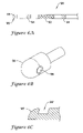
- FIGS. 6A-6C show perspective and alternative detail views of a lead electrode assembly
- FIG. 7 shows a perspective view of an insertion tool bending device
- FIG. 8 shows a perspective partial view of an infusion tubing set
- FIGS. 9A-9B show, in combination and alone, an insertion tool with a splittable sheath and a splittable sheath by itself;
- FIG. 10 shows a patient illustrating relative positions for illustrative incisions
- FIGS. 11A-11J show an illustrative method of electrode insertion
- FIGS. 12A-12B illustrate several aspects of different sensor configurations.
- FIG. 1 illustrates in perspective view a lead electrode assembly insertion tool kit including several components.
- the kit 10 includes a number of items, including a straight insertion tool 20 , a curved insertion tool 40 , a bending tool 100 and an infusion tubing set 110 .
- the kit 10 may further include a splittable sheath (not shown) such as that illustrated in FIGS. 9A-9B .
- the insertion tools 20 , 40 include elongate shafts made of stainless steel tubes, with plastic handles, although other materials may be used as desired for either portion.
- the infusion tubing set 110 will often include a flexible polymeric tubular member, although this is not required.
- the bending tool 100 may be used to adjust the shape of the insertion tools 20 , 40 , although again this is not required. Features of each of these elements are further explained below.
- FIGS. 2A-2B show, in perspective and section views, a straight electrode insertion tool.
- the tool 20 is generally straight distal of its handle 26 , and includes a shaft portion 22 that is preferably stiff enough to provide pushability to a distal end 24 for creating a path through tissue.
- a relatively rigid metallic member such as a stainless steel shaft, is used for the shaft portion 22 .
- the shaft 22 is secured to a handle 26 near its proximal end, where a Luer connector 28 is provided.
- the distal end 24 of the shaft 22 illustrates a number of attachment features, including a groove 30 and a suture hole 32 .
- the groove 30 may be a radial groove allowing for slipknot attachment to a thread such as a suture.
- the suture hole 32 may allow for a thread or suture to be passed therethrough and then tied.
- the end of the tool might also possess specific geometries for attachment to specific electrode designs.
- the tool 20 is shown in a cut-away or section view, with the shaft 22 extending through the handle 26 .
- the shaft 22 defines a lumen 34 that extends from the Luer connector 28 to an infusion port opening into the suture hole 32 .
- the handle 26 may be secured to the shaft 22 in any suitable manner, for example, with adhesives, mechanical securing devices (i.e., mating threads, notches, or the like), heat welding, or by overmolding the handle 26 onto the shaft 22 .
- One way to provide additional mechanical strength to any such attachment is to include an offset bend 36 in the shaft 22 under the handle 26 .
- FIGS. 3A-3B show, in perspective and section views, a curved electrode insertion tool.
- the tool 40 has a gradual or smooth curve which may be selected or shaped to match a patient's anatomy.
- the curve is chosen to correspond to the curvature of a patient's rib, allowing less traumatic passage through the subcutaneous space of a patient along the patient's chest.
- the tool 40 includes a shaft portion 42 that is preferably stiff enough to provide pushability to a distal end 44 for creating a path through tissue.
- a relatively rigid metallic member such as a stainless steel shaft, is used for the shaft portion 42 .
- the shaft 42 is secured to a handle 46 near its proximal end, where a Luer connector 48 is provided.
- a pushable polymeric member may be used, or, alternatively, a braided shaft member including polymeric layers and a braided support structure.
- the distal end 44 of the shaft 42 illustrates a couple of attachment features, including a groove 50 and a suture hole 52 .
- the groove 50 may be a radial groove allowing for slipknot attachment to a thread such as a suture.
- the suture hole 52 may allow for a thread or suture to be passed therethrough and then tied.
- a staple may pass through the hole 52 such that, rather than having a person physically tie or knot a suture, a surgical stapler may be used instead.
- the tool 40 is shown in section or cut-away view with the shaft 42 extending through the handle 46 .
- the shaft 42 defines a lumen 54 that extends from the Luer connector 48 to an infusion port opening into the suture hole 52 .
- the handle 46 may be secured to shaft 42 in any suitable way, for example, with adhesives, mechanical securing devices (i.e., threads, notches, or the like), heat welding, or by overmolding the handle 46 onto the shaft 42 .
- One way to improve the mechanical strength of the bond is to include an offset bend 56 in the shaft 42 under the handle 46 .
- FIGS. 4A-4C show detailed section views of an electrode insertion tool handle.
- the electrode insertion tool handle 60 may correspond to the handles 26 , 46 illustrated in FIGS. 2A-2B and 3 A- 3 B.
- the handle 60 includes a Luer port 62 for providing access to a lumen defined by the shaft 66 .
- the Luer port/valve 62 includes a proximal securing portion 70 for securing to, for example, a fluid infusion device, and a distal securing portion 72 for securing to the shaft 66 .
- a local anesthetic such as lidocaine may be infused.
- Other anesthetics, anti-infection drugs, or drugs designed/chosen to prevent or limit swelling or other tissue injury responses may be infused as well.
- An advantage of providing a medication limiting tissue injury response may be to limit the size of any tissue growth around an implanted lead.
- a substance designed to cause or maximize local tissue injury response may be provided.
- certain tissue adhesives could also be delivered through the lumen.
- the main handle portion 64 may be designed to have a flattened side and a wider side. This design aids a doctor/practitioner in grasping the device during tunneling and pulling with the shaft 66 , as well as providing space for the offset bend 68 shown in FIG. 4A .
- the offset bend 68 of the shaft 66 aids in anchoring the shaft 66 in the main handle portion 64 .
- Other handle designs may be used in accordance with the present invention.
- FIGS. 5A-5B show, in perspective and section views, details of an electrode insertion tool tip.
- the tip 80 may correspond to the distal ends 24 , 44 illustrated in FIGS. 2A-2B and 3 A- 3 B.
- the tip 80 includes a rounded end 82 which may have a “bullet” shape for tunneling between tissue layers while avoiding tunneling through tissue layers.
- the rounded end 82 is tapered to allow tunneling into fatty subcutaneous tissue without perforating the skin.
- two illustrative attachment features including a suture hole 84 and a radial groove 86 allowing for suture attachment using, for example, a slipknot.
- the tip 80 with end 82 , suture hole 84 and groove 86 is also shown in FIG. 5B .
- a lumen 88 that terminates in an infusion port that opens laterally through the suture hole 84 .
- the suture hole 84 serves two functions, both as an attachment feature and as an extension of the infusion port.
- the lumen 88 extends through the rest of the shaft (not shown) to a handle and Luer valve such as those shown in FIGS. 2A-2B and 3 A- 3 B.
- FIGS. 6A-6C show perspective and alternative detail views of a lead electrode assembly.
- the lead electrode assembly 90 is shown as having a number of electrodes, including a coil electrode 92 and two sense electrodes 94 .
- the assembly 90 has a distal tip 96 .
- the distal tip 96 may include a suture hole 98 , although any other attachment feature may be used, such as a radial groove as shown in FIGS. 5A-5B or a hook/notch 98 ′ as shown in FIG. 6C in association with tip 96 ′.
- a loop of suture material (or string, for example) or a staple may be secured to the distal tip 96 , 96 ′ by tightening the loop into the groove 86 or hook/notch 98 ′.
- the inclusion of a coil electrode 92 and two sense electrodes 94 is merely illustrative of one lead electrode assembly that may be inserted with the aid of the methods/devices of the present invention.
- FIG. 7 shows a perspective view of an insertion tool bending device.
- the bending device 100 includes posts 102 separated by a gap 104 .
- the shaft of the chosen device is passed through the gap 104 and turned with respect to the bending tool 100 , allowing the posts 102 to reshape the device with a different curve. This may be done to match a chosen insertion tool more accurately to a patient's anatomy.
- the posts 102 may be modified by including caps, notches, grooves, hooks, overhangs or the like for retaining a device shaft going through the gap 104 to prevent it from slipping out.
- FIG. 8 shows a perspective partial view of an infusion tubing set.
- the tubing set 110 may be used in conjunction with one of the insertion tools 20 , 40 shown in FIGS. 2A-2B or 3 A- 3 B.
- the tubing set 110 is used to provide a flexible extension enabling easy attachment of a fluid infusion device to the Luer valve of a chosen insertion tool.
- the tubing set 110 includes first and second connectors 112 , 114 and a flexible tubular shaft 116 therebetween.
- FIGS. 9A-9B show, in combination and alone, an insertion tool with a splittable sheath and a splittable sheath by itself.
- FIG. 9A illustrates an insertion tool 150 having a handle 152 and a shaft 154 extending to a distal tip 156 , with a splittable sheath 158 disposed thereon.
- the splittable sheath 158 is sized to snugly fit over the shaft 154 , and is preferably shorter than the shaft 154 such that the distal end 156 can extend distally of the splittable sheath 158 .
- the splittable sheath 158 has a proximal handle portion 160 and a distal end 162 .
- the distal end 162 may be tapered or thinned such that there is no leading “shoulder” during insertion to tissue.
- the splittable sheath 158 is thin enough that the distal end 162 of the splittable sheath 158 does not create significant drag during insertion, and does not require thinning, grinding, or the like.
- the insertion tool 150 may include a proximally facing lip near its distal end for seating the distal end of the splittable sheath 152 .
- a proximally facing lip may be provided by preloading the splittable sheath 152 on the shaft and then providing an overlay or separate tip that can be secured (i.e., by heating, welding or adhesive) to the distal end of the shaft.
- the distal end 162 of the splittable sheath 158 may be ground to smooth out the distal shoulder.
- the splittable sheath 158 also includes a region of longitudinal weakness 164 for splitting the handle 160 , which also extends toward the distal end 162 , allowing for splitting of the sheath itself.
- FIG. 10 shows a patient illustrating relative positions for incisions in an example procedure.
- the patient 200 is shown with the median plane 202 defined and a rough illustration of the heart 204 provided.
- Incision locations for a first incision 206 and a second incision 208 are shown, again as a relatively rough approximation.
- the incisions 206 , 208 both lie over the same rib or between the same pair of ribs of the patient 200 .
- Each incision is deep enough to enable subcutaneous access, but preferably does not extend further into patient 200 .
- Such incisions may be made over any of the patients ribs, but are preferably made somewhere between the third and twelfth ribs of the patient.
- the line from the first incision to the second incision tracks, at least partly, the inframammary crease.
- the second incision is also preferably made in the region of the left anterior axillary line. While these are presently preferred locations, the specific locations of each incision may vary widely within the context of the present invention.
- FIGS. 11A-11J show an illustrative method of electrode insertion.
- FIG. 11A illustrates a first step after the making of a first incision 206 and a second incision 208 in a patient 200 .
- a pocket 207 has been defined in the subcutaneous region of the patient 200 .
- the pocket 207 may be formed by inserting a trocar through the second incision and separating tissue layers with the trocar to define a subcutaneous pocket 207 or by using manual blunt dissection for receipt of an implantable device.
- An insertion tool 210 (illustrated as including a splittable sheath 218 thereon) is about to be inserted through the first opening 206 . As shown in FIG.
- the insertion tool 210 is advanced from the first opening 206 toward and through the second opening, tunneling a path through the subcutaneous tissue along the way. While advancement of the distal end 212 through the second incision 208 is shown, this extent of insertion is not necessary. It is sufficient that the insertion tool 210 is advanced far enough to provide access from outside of incision 208 to the distal end 212 of the insertion tool 210 for access to an attachment feature.
- the attachment feature shown in FIG. 11B is shown, for illustrative purposes, as including a suture hole 216 .
- a local anesthetic such as Lidocaine or the like may be supplied by infusion through a Luer hub 214 and passage through a lumen in the insertion tool 210 .
- a next step includes attaching the distal end of a lead electrode assembly 220 to the distal end 212 of the insertion tool 210 using a suture loop 224 that passes through the insertion tool 210 suture hole 216 and a corresponding suture hole 222 on the lead electrode assembly 220 .
- the illustrative lead electrode assembly 220 is shown having two sensing and one shocking electrode thereon; such a configuration is merely illustrative of one lead assembly, and use of the present invention need not be limited to such electrode lead assemblies.
- suture holes 216 , 222 other attachment features such as hooks or radial grooves, as illustrated above, may be used. Magnetic, screw-type, locking ball, snap fit, or other types of attachment may be substituted as well, though for the purposes of illustration, magnetic, screw-type, locking ball and snap fit attachment features have not been shown herein. It is sufficient that the attachment feature enable attachment of the insertion tool distal end to another element such as a lead electrode assembly.
- the suture holes, hooks or radial grooves allow for relatively simple and reliable attachment using readily available (and strong) suture material or staples.
- attaching a suture or staple is relatively simple.
- any type of knot may be used, from simple slipknots to many stronger and more complex knots, to achieve a strong attachment. Removal is also simple, easy, and foolproof, being performed by merely cutting the suture/staple 224 .
- FIG. 11D a next step is illustrated wherein the insertion tool 210 is withdrawn through the first incision 206 , pulling the lead electrode assembly 220 into the path tunneled by the insertion tool 210 between the incisions 206 , 208 using the suture 224 and suture holes 216 , 222 . As shown, this step is performed until at least the suture 224 can be accessed from outside the patient.
- the method may stop here.
- the lead assembly 220 With the lead electrode assembly 220 pulled into the path between the incisions 206 , 208 , the lead assembly 220 may be sized such that a canister 230 attached to the proximal end of the lead electrode assembly 220 is pulled into the pocket 207 .
- the suture 224 is then cut and the incisions 206 , 208 sewn shut, such that implantation is essentially complete insofar as device placement is concerned. Because the lead assembly 220 is pulled into position after tunneling, rather than being carried or pushed into position, the resultant strains on the lead assembly 220 are reduced. Further, by advancing from a first incision 206 at a definite location to a second incision 208 at another definite location, both ends of the path so defined can be tightly controlled. Thus, placement inaccuracy is avoided.
- FIGS. 11E-11J An alternative embodiment continues in FIGS. 11E-11J .
- the lead electrode assembly 220 is pulled for a greater distance allowing access to the distal end 222 thereof.
- the lead assembly 220 may be pulled sufficiently to cause it to exit the first incision 206 by a certain amount.
- the insertion tool 210 with the splittable sheath 218 is re-inserted into the first incision 206 , this time in a different direction than before.
- a first, preferably curved, insertion tool is used during the steps shown in FIGS. 11A-11E while a second, preferably straight, insertion tool is used in FIGS. 11F-11J , with the splittable sheath provided only for the straight insertion tool.
- the insertion tool 210 is inserted via the first incision 206 toward a chosen point or location X 232 located cephalic (directed toward the head of the patient) of the first incision.
- a line drawn from the first incision 206 to the second incision 208 is at an angle ⁇ , between about 20 and 160 degrees, with respect to a line drawn from the first incision toward location X 232 . More preferably, the angle ⁇ is around about 90 degrees, being in the range of between 75 and 105 degrees.
- the insertion tool 210 After the insertion tool 210 has tunneled a desired distance, and while the splittable sheath 218 may still be accessed from outside the patient, the insertion tool 210 is removed to leave the splittable sheath 218 in place, as shown in FIG. 11H .
- the distal end of the lead electrode assembly 220 is directed into the splittable sheath 218 , as also shown in FIG. 11H .
- the splittable sheath 218 may be removed by grasping handles 234 and tearing the sheath apart, as shown in FIG. 11I . At this point, as shown in FIG.
- the lead assembly 220 is preferably far enough into the patient longitudinally that the canister 230 has entered the pocket 207 and is inside the patient 200 , through incision 208 . As shown at FIG. 11J , the incisions 206 , 208 are then closed, leaving the lead electrode assembly 220 and canister 230 fully implanted. After this point, the implantation is complete, and a variety of methods may be used to “activate” and/or program the canister 230 and whatever electronics for pacing and/or defibrillation are contained therein.
- An advantage of the configuration for implantation of the electrode assembly shown in FIG. 11J is that the electrodes on the lead electrode assembly 220 are aligned in a new manner with respect to the canister 230 .
- the canister 230 was often generally collinear with the electrodes on the lead electrode assembly.
- An electrode on the canister 230 may be offset from the axial direction of the lead electrode assembly, allowing for some minor angular variation in exchange for reducing the distance between electrodes. Even if there were more than two sensing electrodes, the signals received by distinct sensing electrode pairs would have little variation, since collinear electrodes generally do not receive significantly different signals in the far-field, except for pairs that are close together and therefore yield poor signal anyway.
- the assembly inserted as shown in FIG. 11J enables multiple sensors on the distal end of the lead assembly 220 , along with at least one canister electrode, to provide a wider variation in angular orientation, without closing the distance between the canister and the electrodes.
- FIGS. 12A-12B help to further illustrate several relevant sensor characteristics. It should be recognized that, at least with far-field sensing of electrical activity in the heart, parallel sensor pairs tend to receive highly correlated signals. Over a short distance, there is little to be gained by having more than two sensors along the same line. Given a sensing lead electrode assembly and canister device as shown and oriented in FIG. 12A , dead signal sensing problems can arise.
- three sensors X, Y, and Z on a lead assembly 312 coupled to a canister 310 define three sensor pair vectors 314 , 316 , and 318 which have angles ⁇ , ⁇ , and ⁇ therebetween.
- the above problem is avoided when the electrodes X, Y, and Z are not generally collinear, as shown. Angles ⁇ , ⁇ and ⁇ are all relatively large, each being bigger than about fifteen degrees. If orthogonal sensing pairs are used, when the minimum signal is received by one of the pairs, a maximum signal is received by the other pair.
- the insertion method is performed so that three sensors define a plane which at least partly intersects the heart.
- sensors are placed so that at least one angle between sensor pair vectors is greater than 30 degrees. More preferably, at least one angle between sensor pair vectors is greater than about 60 degrees, while most preferably at least one angle between sensor pair vectors is in the range of about 70-90 degrees. Note that when referring to angles between sensor pair vectors, the angles referred to are the lesser angles between pairs of intersecting vectors.
- Another preferred layout is one in which the sine of the angles between sensing vectors is intentionally increased, preferably so that the sine of at least one such angle between sensing vectors is greater than or equal to about 0.5.
- FIG. 12B illustrates only three sensors for the purpose of simplicity. It may be preferable to include four electrodes, with one canister electrode being both a sensing and a shocking electrode, while two lead electrodes are only sensing electrodes provided distal of and proximal of a shocking/sensing electrode coil. Indeed, unless specifically limited by the use of non-inclusive language in the following claims, the number of sensors used in a lead electrode assembly should not be understood as limiting the present invention.
Abstract
Description
Claims (21)
Priority Applications (14)
| Application Number | Priority Date | Filing Date | Title |
|---|---|---|---|
| US11/006,291 US7655014B2 (en) | 2004-12-06 | 2004-12-06 | Apparatus and method for subcutaneous electrode insertion |
| PCT/US2005/037759 WO2006062590A1 (en) | 2004-12-06 | 2005-10-19 | Apparatus and method for subcutaneous electrode insertion |
| EP05810131A EP1830918B1 (en) | 2004-12-06 | 2005-10-19 | Apparatus for subcutaneous electrode insertion |
| AU2005314611A AU2005314611B2 (en) | 2004-12-06 | 2005-10-19 | Apparatus and method for subcutaneous electrode insertion |
| DE602005021695T DE602005021695D1 (en) | 2004-12-06 | 2005-10-19 | DEVICE FOR THE SUBCUTANEOUS INTRODUCTION OF AN ELECTRODE |
| CA2588024A CA2588024C (en) | 2004-12-06 | 2005-10-19 | Apparatus and method for subcutaneous electrode insertion |
| CN200580041756XA CN101072601B (en) | 2004-12-06 | 2005-10-19 | Apparatus and method for subcutaneous electrode insertion |
| AT05810131T ATE469669T1 (en) | 2004-12-06 | 2005-10-19 | DEVICE FOR SUBCUTANEOUS INSERTION OF AN ELECTRODE |
| ES05810131T ES2346551T3 (en) | 2004-12-06 | 2005-10-19 | APPARATUS FOR SUBCUTANEOUS ELECTRODE INSERTION. |
| JP2007544346A JP4943343B2 (en) | 2004-12-06 | 2005-10-19 | Subcutaneous electrode insertion apparatus and method |
| US12/698,627 US8157813B2 (en) | 2004-12-06 | 2010-02-02 | Apparatus and method for subcutaneous electrode insertion |
| AU2011202081A AU2011202081B2 (en) | 2004-12-06 | 2011-05-05 | Apparatus and method for subcutaneous electrode insertion |
| US13/436,438 US8801729B2 (en) | 2004-12-06 | 2012-03-30 | Apparatus and method for subcutaneous electrode insertion |
| US14/324,407 US20140324068A1 (en) | 2004-12-06 | 2014-07-07 | Apparatus for subcutaneous electrode insertion |
Applications Claiming Priority (1)
| Application Number | Priority Date | Filing Date | Title |
|---|---|---|---|
| US11/006,291 US7655014B2 (en) | 2004-12-06 | 2004-12-06 | Apparatus and method for subcutaneous electrode insertion |
Related Child Applications (1)
| Application Number | Title | Priority Date | Filing Date |
|---|---|---|---|
| US12/698,627 Continuation US8157813B2 (en) | 2004-12-06 | 2010-02-02 | Apparatus and method for subcutaneous electrode insertion |
Publications (2)
| Publication Number | Publication Date |
|---|---|
| US20060122676A1 US20060122676A1 (en) | 2006-06-08 |
| US7655014B2 true US7655014B2 (en) | 2010-02-02 |
Family
ID=36575406
Family Applications (4)
| Application Number | Title | Priority Date | Filing Date |
|---|---|---|---|
| US11/006,291 Active 2028-04-21 US7655014B2 (en) | 2004-12-06 | 2004-12-06 | Apparatus and method for subcutaneous electrode insertion |
| US12/698,627 Active 2025-09-08 US8157813B2 (en) | 2004-12-06 | 2010-02-02 | Apparatus and method for subcutaneous electrode insertion |
| US13/436,438 Active 2025-05-27 US8801729B2 (en) | 2004-12-06 | 2012-03-30 | Apparatus and method for subcutaneous electrode insertion |
| US14/324,407 Abandoned US20140324068A1 (en) | 2004-12-06 | 2014-07-07 | Apparatus for subcutaneous electrode insertion |
Family Applications After (3)
| Application Number | Title | Priority Date | Filing Date |
|---|---|---|---|
| US12/698,627 Active 2025-09-08 US8157813B2 (en) | 2004-12-06 | 2010-02-02 | Apparatus and method for subcutaneous electrode insertion |
| US13/436,438 Active 2025-05-27 US8801729B2 (en) | 2004-12-06 | 2012-03-30 | Apparatus and method for subcutaneous electrode insertion |
| US14/324,407 Abandoned US20140324068A1 (en) | 2004-12-06 | 2014-07-07 | Apparatus for subcutaneous electrode insertion |
Country Status (10)
| Country | Link |
|---|---|
| US (4) | US7655014B2 (en) |
| EP (1) | EP1830918B1 (en) |
| JP (1) | JP4943343B2 (en) |
| CN (1) | CN101072601B (en) |
| AT (1) | ATE469669T1 (en) |
| AU (2) | AU2005314611B2 (en) |
| CA (1) | CA2588024C (en) |
| DE (1) | DE602005021695D1 (en) |
| ES (1) | ES2346551T3 (en) |
| WO (1) | WO2006062590A1 (en) |
Cited By (95)
| Publication number | Priority date | Publication date | Assignee | Title |
|---|---|---|---|---|
| US20080208303A1 (en) * | 2007-02-28 | 2008-08-28 | Rutten Jean J G | Implantable medical device system with fixation member |
| US20080312677A1 (en) * | 2006-05-05 | 2008-12-18 | I-Flow Corporation | Soft tissue tunneling device |
| US20090182401A1 (en) * | 2008-01-10 | 2009-07-16 | Arkady Glukhovsky | Methods and apparatus for implanting electronic implants within the body |
| US20100036465A1 (en) * | 2008-08-07 | 2010-02-11 | Arkady Glukhovsky | Insertion tools and methods for an electrical stimulation implant |
| US20100094369A1 (en) * | 2008-03-07 | 2010-04-15 | Cameron Health, Inc. | Methods and Devices for Accurately Classifying Cardiac Activity |
| US20100152798A1 (en) * | 2008-12-12 | 2010-06-17 | Rick Sanghera | Electrode Spacing in a Subcutaneous Implantable Cardiac Stimulus Device |
| US20100318098A1 (en) * | 2006-04-04 | 2010-12-16 | Lund Robert E | Systems and Methods for Implanting Medical Devices |
| US8160687B2 (en) | 2008-05-07 | 2012-04-17 | Cameron Health, Inc. | Methods and devices for accurately classifying cardiac activity |
| US8265737B2 (en) | 2009-10-27 | 2012-09-11 | Cameron Health, Inc. | Methods and devices for identifying overdetection of cardiac signals |
| WO2012145600A2 (en) | 2011-04-22 | 2012-10-26 | Cameron Health, Inc. | Robust rate calculation in an implantable cardiac stimulus or monitoring device |
| WO2012170868A1 (en) | 2011-06-09 | 2012-12-13 | Cameron Health, Inc. | Antitachycaradia pacing pulse from a subcutaneous defibrillator |
| US8494630B2 (en) | 2008-01-18 | 2013-07-23 | Cameron Health, Inc. | Data manipulation following delivery of a cardiac stimulus in an implantable cardiac stimulus device |
| US8548573B2 (en) | 2010-01-18 | 2013-10-01 | Cameron Health, Inc. | Dynamically filtered beat detection in an implantable cardiac device |
| US8565878B2 (en) | 2008-03-07 | 2013-10-22 | Cameron Health, Inc. | Accurate cardiac event detection in an implantable cardiac stimulus device |
| US8744555B2 (en) | 2009-10-27 | 2014-06-03 | Cameron Health, Inc. | Adaptive waveform appraisal in an implantable cardiac system |
| US8801729B2 (en) | 2004-12-06 | 2014-08-12 | Cameron Health, Inc. | Apparatus and method for subcutaneous electrode insertion |
| US8831711B2 (en) | 2012-06-04 | 2014-09-09 | Cameron Health, Inc. | Implantable cardiac systems with baseline correction in response to noise detection |
| US20140330248A1 (en) * | 2013-05-06 | 2014-11-06 | Medtronic, Inc. | Systems and methods for implanting a medical electrical lead |
| US9149637B2 (en) | 2009-06-29 | 2015-10-06 | Cameron Health, Inc. | Adaptive confirmation of treatable arrhythmia in implantable cardiac stimulus devices |
| US9149645B2 (en) | 2013-03-11 | 2015-10-06 | Cameron Health, Inc. | Methods and devices implementing dual criteria for arrhythmia detection |
| US9216284B2 (en) | 2006-08-01 | 2015-12-22 | Cameron Health, Inc. | Electrode insertion tools, lead assemblies, kits and methods for placement of cardiac device electrodes |
| US9220913B2 (en) | 2013-05-06 | 2015-12-29 | Medtronics, Inc. | Multi-mode implantable medical device |
| US9326821B2 (en) | 2011-04-29 | 2016-05-03 | Medtronic, Inc. | Medical tunneling device and method |
| US9457186B2 (en) | 2010-11-15 | 2016-10-04 | Bluewind Medical Ltd. | Bilateral feedback |
| US9554714B2 (en) | 2014-08-14 | 2017-01-31 | Cameron Health Inc. | Use of detection profiles in an implantable medical device |
| US9597521B2 (en) | 2015-01-21 | 2017-03-21 | Bluewind Medical Ltd. | Transmitting coils for neurostimulation |
| US9610436B2 (en) | 2013-11-12 | 2017-04-04 | Medtronic, Inc. | Implant tools with attachment feature and multi-positional sheath and implant techniques utilizing such tools |
| WO2017062405A1 (en) | 2015-10-06 | 2017-04-13 | Cardiac Pacemakers, Inc. | Fixation device for a subcutaneous electrode |
| US9636505B2 (en) | 2014-11-24 | 2017-05-02 | AtaCor Medical, Inc. | Cardiac pacing sensing and control |
| US9636512B2 (en) | 2014-11-05 | 2017-05-02 | Medtronic, Inc. | Implantable cardioverter-defibrillator (ICD) system having multiple common polarity extravascular defibrillation electrodes |
| US9707389B2 (en) | 2014-09-04 | 2017-07-18 | AtaCor Medical, Inc. | Receptacle for pacemaker lead |
| US9713707B2 (en) | 2015-11-12 | 2017-07-25 | Bluewind Medical Ltd. | Inhibition of implant migration |
| US9717923B2 (en) | 2013-05-06 | 2017-08-01 | Medtronic, Inc. | Implantable medical device system having implantable cardioverter-defibrillator (ICD) system and substernal leadless pacing device |
| US9744366B2 (en) | 2006-05-26 | 2017-08-29 | Cameron Health, Inc. | Sensing vector selection in a cardiac stimulus device with postural assessment |
| US9764146B2 (en) | 2015-01-21 | 2017-09-19 | Bluewind Medical Ltd. | Extracorporeal implant controllers |
| US9782589B2 (en) | 2015-06-10 | 2017-10-10 | Bluewind Medical Ltd. | Implantable electrostimulator for improving blood flow |
| US9861812B2 (en) | 2012-12-06 | 2018-01-09 | Blue Wind Medical Ltd. | Delivery of implantable neurostimulators |
| WO2018026922A1 (en) | 2016-08-05 | 2018-02-08 | Cardiac Pacemakers, Inc. | Implantation of an active medical device using the internal thoracic vasculature |
| US9974944B2 (en) | 2010-07-29 | 2018-05-22 | Cameron Health, Inc. | Subcutaneous leads and methods of implant and explant |
| US9993171B2 (en) | 2015-04-08 | 2018-06-12 | Cameron Health, Inc. | Automated screening methods and apparatuses for implantable medical devices |
| US10004896B2 (en) | 2015-01-21 | 2018-06-26 | Bluewind Medical Ltd. | Anchors and implant devices |
| US10105540B2 (en) | 2015-11-09 | 2018-10-23 | Bluewind Medical Ltd. | Optimization of application of current |
| US10105187B2 (en) | 2015-08-27 | 2018-10-23 | Medtronic, Inc. | Systems, apparatus, methods and computer-readable storage media facilitating surgical procedures utilizing augmented reality |
| US10117664B2 (en) | 2015-02-13 | 2018-11-06 | Heartware, Inc. | Combined tunneling tools |
| US10118027B2 (en) | 2013-11-12 | 2018-11-06 | Medtronic, Inc. | Open channel implant tools having an attachment feature and implant techniques utilizing such tools |
| US10124178B2 (en) | 2016-11-23 | 2018-11-13 | Bluewind Medical Ltd. | Implant and delivery tool therefor |
| US10154794B2 (en) | 2014-04-25 | 2018-12-18 | Medtronic, Inc. | Implantable cardioverter-defibrillator (ICD) tachyarrhythmia detection modifications responsive to detected pacing |
| WO2019036571A1 (en) | 2017-08-17 | 2019-02-21 | Cardiac Pacemakers, Inc. | Single incision subcutaneous implantable defibrillation system |
| US10226197B2 (en) | 2014-04-25 | 2019-03-12 | Medtronic, Inc. | Pace pulse detector for an implantable medical device |
| US10328268B2 (en) | 2014-09-04 | 2019-06-25 | AtaCor Medical, Inc. | Cardiac pacing |
| US10349978B2 (en) | 2014-12-18 | 2019-07-16 | Medtronic, Inc. | Open channel implant tool with additional lumen and implant techniques utilizing such tools |
| US10434307B2 (en) | 2013-10-15 | 2019-10-08 | Medtronic, Inc. | Methods and devices for subcutaneous lead implantation |
| US10448855B2 (en) | 2014-04-25 | 2019-10-22 | Medtronic, Inc. | Implantable medical device (IMD) sensing modifications responsive to detected pacing pulses |
| US10471267B2 (en) | 2013-05-06 | 2019-11-12 | Medtronic, Inc. | Implantable cardioverter-defibrillator (ICD) system including substernal lead |
| US10532203B2 (en) | 2013-05-06 | 2020-01-14 | Medtronic, Inc. | Substernal electrical stimulation system |
| US10537731B2 (en) | 2016-11-17 | 2020-01-21 | Cardiac Pacemakers, Inc. | Transvenous mediastinum access for the placement of cardiac pacing and defibrillation electrodes |
| WO2020023487A1 (en) | 2018-07-23 | 2020-01-30 | Cardiac Pacemakers, Inc. | Retention mechanism for an implantable lead |
| US10556117B2 (en) | 2013-05-06 | 2020-02-11 | Medtronic, Inc. | Implantable cardioverter-defibrillator (ICD) system including substernal pacing lead |
| US10617402B2 (en) | 2015-07-22 | 2020-04-14 | Cameron Health, Inc. | Minimally invasive method to implant a subcutaneous electrode |
| US10653888B2 (en) | 2012-01-26 | 2020-05-19 | Bluewind Medical Ltd | Wireless neurostimulators |
| US10675476B2 (en) | 2016-12-22 | 2020-06-09 | Cardiac Pacemakers, Inc. | Internal thoracic vein placement of a transmitter electrode for leadless stimulation of the heart |
| US10722704B2 (en) | 2018-05-07 | 2020-07-28 | Pacesetter, Inc. | Implantable medical systems and methods including pulse generators and leads |
| US10729456B2 (en) | 2014-12-18 | 2020-08-04 | Medtronic, Inc. | Systems and methods for deploying an implantable medical electrical lead |
| US10743960B2 (en) | 2014-09-04 | 2020-08-18 | AtaCor Medical, Inc. | Cardiac arrhythmia treatment devices and delivery |
| US10751526B2 (en) | 2017-10-25 | 2020-08-25 | Cardiac Pacemakers, Inc. | Subcutaneous lead implantation |
| US10751543B2 (en) | 2016-12-22 | 2020-08-25 | Cardiac Pacemakers, Inc. | Azygos, internal thoracic, and/or intercostal vein implantation and use of medical devices |
| US10765860B2 (en) | 2018-05-07 | 2020-09-08 | Pacesetter, Inc. | Subcutaneous implantation medical device with multiple parasternal-anterior electrodes |
| US10786679B2 (en) | 2016-12-21 | 2020-09-29 | Cardiac Pacemakers, Inc. | Lead with integrated electrodes |
| US10806932B2 (en) | 2017-03-20 | 2020-10-20 | Cardiac Pacemakers, Inc. | Implantable medical device |
| US10842520B2 (en) | 2015-10-12 | 2020-11-24 | Cardiac Pacemakers, Inc. | Dottering tools for implanting medical devices |
| US10842988B2 (en) | 2014-06-02 | 2020-11-24 | Medtronic, Inc. | Over-the-wire delivery of a substernal lead |
| US10850067B2 (en) | 2016-12-21 | 2020-12-01 | Cardiac Pacemakers, Inc. | Implantation of an active medical device using the intercostal vein |
| US10881850B2 (en) | 2012-03-06 | 2021-01-05 | Medtronic, Inc. | Self-tunneling lead |
| US10888697B2 (en) | 2017-08-18 | 2021-01-12 | Cardiac Pacemakers, Inc. | Fixation mechanism for an implantable lead |
| US10905884B2 (en) | 2012-07-20 | 2021-02-02 | Cardialen, Inc. | Multi-stage atrial cardioversion therapy leads |
| US20210069472A1 (en) * | 2019-09-06 | 2021-03-11 | Wuxi people's hospital | Magnetic navigation-guided tear-away sheath for cardiac conduction bundle pacing |
| US10980570B2 (en) | 2017-01-12 | 2021-04-20 | Cardiac Pacemakers, Inc. | Implantation of an active medical device using the internal thoracic vasculature |
| US11020075B2 (en) | 2017-05-12 | 2021-06-01 | Cardiac Pacemakers, Inc. | Implantation of an active medical device using the internal thoracic vasculature |
| US11045643B2 (en) | 2018-05-07 | 2021-06-29 | Pacesetter, Inc. | Single-site implantation methods for medical devices having multiple leads |
| US11077297B2 (en) | 2017-04-18 | 2021-08-03 | Cardiac Pacemakers, Inc. | Active medical device with attachment features |
| US11077299B2 (en) | 2017-03-07 | 2021-08-03 | Cardiac Pacemakers, Inc. | Implantation of an active medical device |
| US11083491B2 (en) | 2014-12-09 | 2021-08-10 | Medtronic, Inc. | Extravascular implant tools utilizing a bore-in mechanism and implant techniques using such tools |
| US11097109B2 (en) | 2014-11-24 | 2021-08-24 | AtaCor Medical, Inc. | Cardiac pacing sensing and control |
| US11116966B2 (en) | 2017-08-17 | 2021-09-14 | Cardiac Pacemakers, Inc. | Retention mechanism for an implantable lead |
| US11147964B2 (en) | 2018-04-23 | 2021-10-19 | Cardiac Pacemakers, Inc. | Subcutaneous lead fixation member |
| WO2021211736A1 (en) * | 2020-04-15 | 2021-10-21 | Senseonics, Incorporated | Insertion tool with a dissector |
| US11213685B2 (en) | 2017-06-13 | 2022-01-04 | Bluewind Medical Ltd. | Antenna configuration |
| US11219775B2 (en) | 2018-05-01 | 2022-01-11 | Cardiac Pacemakers, Inc. | Retention mechanism for an implantable lead |
| US11400299B1 (en) | 2021-09-14 | 2022-08-02 | Rainbow Medical Ltd. | Flexible antenna for stimulator |
| US11432845B2 (en) | 2019-04-09 | 2022-09-06 | Senseonics, Incorporated | Insertion tool with a dissector |
| US11433232B2 (en) | 2013-05-06 | 2022-09-06 | Medtronic, Inc. | Devices and techniques for anchoring an implantable medical device |
| USD980420S1 (en) * | 2019-08-01 | 2023-03-07 | Catheter Precision, Inc. | Kit of positioning patches |
| US11666771B2 (en) | 2020-05-29 | 2023-06-06 | AtaCor Medical, Inc. | Implantable electrical leads and associated delivery systems |
| US11672975B2 (en) | 2019-05-29 | 2023-06-13 | AtaCor Medical, Inc. | Implantable electrical leads and associated delivery systems |
| US11951316B2 (en) | 2021-12-09 | 2024-04-09 | Bluewind Medical Ltd. | Antenna configuration |
Families Citing this family (83)
| Publication number | Priority date | Publication date | Assignee | Title |
|---|---|---|---|---|
| US8340779B2 (en) | 2003-08-29 | 2012-12-25 | Medtronic, Inc. | Percutaneous flat lead introducer |
| US7542800B2 (en) * | 2005-04-05 | 2009-06-02 | Cardiac Pacemakers, Inc. | Method and apparatus for synchronizing neural stimulation to cardiac cycles |
| WO2006135753A1 (en) | 2005-06-09 | 2006-12-21 | Medtronic, Inc. | Introducer for therapy delivery elements |
| WO2007130605A1 (en) * | 2006-05-05 | 2007-11-15 | I-Flow Corporation | Soft tissue tunneling device |
| US7655004B2 (en) | 2007-02-15 | 2010-02-02 | Ethicon Endo-Surgery, Inc. | Electroporation ablation apparatus, system, and method |
| US8579897B2 (en) | 2007-11-21 | 2013-11-12 | Ethicon Endo-Surgery, Inc. | Bipolar forceps |
| US20090112059A1 (en) | 2007-10-31 | 2009-04-30 | Nobis Rudolph H | Apparatus and methods for closing a gastrotomy |
| GB0800615D0 (en) * | 2008-01-14 | 2008-02-20 | Hypo Safe As | Implantable electronic device |
| WO2009097527A1 (en) * | 2008-01-30 | 2009-08-06 | Transoma Medical, Inc. | Minimally invasive physiologic parameter recorder and introducer system |
| GB0803055D0 (en) * | 2008-02-20 | 2008-03-26 | Fitzpatrick Adam P | Surgical tool and method of use |
| KR102470819B1 (en) * | 2008-05-07 | 2022-11-28 | 더 케무어스 컴퍼니 에프씨, 엘엘씨 | Compositions comprising 1,1,1,2,3-pentafluoropropane or 2,3,3,3- tetrafluoropropene |
| US8771260B2 (en) | 2008-05-30 | 2014-07-08 | Ethicon Endo-Surgery, Inc. | Actuating and articulating surgical device |
| US8906035B2 (en) | 2008-06-04 | 2014-12-09 | Ethicon Endo-Surgery, Inc. | Endoscopic drop off bag |
| US8403926B2 (en) | 2008-06-05 | 2013-03-26 | Ethicon Endo-Surgery, Inc. | Manually articulating devices |
| US8888792B2 (en) | 2008-07-14 | 2014-11-18 | Ethicon Endo-Surgery, Inc. | Tissue apposition clip application devices and methods |
| US20100030230A1 (en) * | 2008-07-31 | 2010-02-04 | Medtronic, Inc. | Medical device system and apparatus for guiding the placement of a subcutaneous device |
| US8409200B2 (en) | 2008-09-03 | 2013-04-02 | Ethicon Endo-Surgery, Inc. | Surgical grasping device |
| US8157834B2 (en) | 2008-11-25 | 2012-04-17 | Ethicon Endo-Surgery, Inc. | Rotational coupling device for surgical instrument with flexible actuators |
| US8361066B2 (en) | 2009-01-12 | 2013-01-29 | Ethicon Endo-Surgery, Inc. | Electrical ablation devices |
| US20110098704A1 (en) | 2009-10-28 | 2011-04-28 | Ethicon Endo-Surgery, Inc. | Electrical ablation devices |
| US8608652B2 (en) | 2009-11-05 | 2013-12-17 | Ethicon Endo-Surgery, Inc. | Vaginal entry surgical devices, kit, system, and method |
| US8496574B2 (en) | 2009-12-17 | 2013-07-30 | Ethicon Endo-Surgery, Inc. | Selectively positionable camera for surgical guide tube assembly |
| US8506564B2 (en) | 2009-12-18 | 2013-08-13 | Ethicon Endo-Surgery, Inc. | Surgical instrument comprising an electrode |
| US9028483B2 (en) | 2009-12-18 | 2015-05-12 | Ethicon Endo-Surgery, Inc. | Surgical instrument comprising an electrode |
| US9005198B2 (en) | 2010-01-29 | 2015-04-14 | Ethicon Endo-Surgery, Inc. | Surgical instrument comprising an electrode |
| US9381030B2 (en) * | 2010-07-15 | 2016-07-05 | Nuvectra Corporation | Tunneling tool for implantable leads |
| US10092291B2 (en) | 2011-01-25 | 2018-10-09 | Ethicon Endo-Surgery, Inc. | Surgical instrument with selectively rigidizable features |
| US20120191075A1 (en) * | 2011-01-25 | 2012-07-26 | Ethicon Endo-Surgery, Inc. | Method and devices for pulling a tether through an organ wall |
| US9233241B2 (en) | 2011-02-28 | 2016-01-12 | Ethicon Endo-Surgery, Inc. | Electrical ablation devices and methods |
| US9314620B2 (en) | 2011-02-28 | 2016-04-19 | Ethicon Endo-Surgery, Inc. | Electrical ablation devices and methods |
| US9254169B2 (en) | 2011-02-28 | 2016-02-09 | Ethicon Endo-Surgery, Inc. | Electrical ablation devices and methods |
| US9049987B2 (en) | 2011-03-17 | 2015-06-09 | Ethicon Endo-Surgery, Inc. | Hand held surgical device for manipulating an internal magnet assembly within a patient |
| US10086190B2 (en) | 2011-10-25 | 2018-10-02 | Medtronic, Inc. | Methods, tools, and assemblies for implantation of medical leads having distal tip anchors |
| EP2788073B1 (en) | 2011-11-10 | 2018-03-21 | Medtronic Inc. | Introduction and anchoring tool for an implantable medical device element |
| US20130274845A1 (en) * | 2012-04-10 | 2013-10-17 | NeuroAccess Technologies | Systems, devices and methods for distal fixation of a medical device |
| US9427255B2 (en) | 2012-05-14 | 2016-08-30 | Ethicon Endo-Surgery, Inc. | Apparatus for introducing a steerable camera assembly into a patient |
| US9078662B2 (en) | 2012-07-03 | 2015-07-14 | Ethicon Endo-Surgery, Inc. | Endoscopic cap electrode and method for using the same |
| US9545290B2 (en) | 2012-07-30 | 2017-01-17 | Ethicon Endo-Surgery, Inc. | Needle probe guide |
| US9572623B2 (en) | 2012-08-02 | 2017-02-21 | Ethicon Endo-Surgery, Inc. | Reusable electrode and disposable sheath |
| US10314649B2 (en) | 2012-08-02 | 2019-06-11 | Ethicon Endo-Surgery, Inc. | Flexible expandable electrode and method of intraluminal delivery of pulsed power |
| US9277957B2 (en) | 2012-08-15 | 2016-03-08 | Ethicon Endo-Surgery, Inc. | Electrosurgical devices and methods |
| WO2014061162A1 (en) * | 2012-10-19 | 2014-04-24 | テルモ株式会社 | Connection mechanism for electrical stimulus device |
| WO2014073049A1 (en) * | 2012-11-07 | 2014-05-15 | テルモ株式会社 | Insertion tool |
| US20140135786A1 (en) * | 2012-11-09 | 2014-05-15 | Naris Llc | Medical procedure access kit |
| US10098527B2 (en) | 2013-02-27 | 2018-10-16 | Ethidcon Endo-Surgery, Inc. | System for performing a minimally invasive surgical procedure |
| US9579065B2 (en) | 2013-03-12 | 2017-02-28 | Cameron Health Inc. | Cardiac signal vector selection with monophasic and biphasic shape consideration |
| EP2968915A1 (en) * | 2013-03-13 | 2016-01-20 | Boston Scientific Neuromodulation Corporation | System and method for making and using a lead introducer for an implantable electrical stimulation system |
| US9472916B2 (en) | 2013-03-14 | 2016-10-18 | Medtronic, Inc. | Distal connector assemblies for medical lead extensions |
| US10391303B2 (en) | 2013-03-14 | 2019-08-27 | Medtronic, Inc. | Tools and methods for implantation of implantable medical lead extensions or catheters |
| US9149627B2 (en) | 2013-03-14 | 2015-10-06 | Medtronic, Inc. | Kits and methods for implanting an implantable lead extension |
| US11389195B2 (en) | 2014-01-24 | 2022-07-19 | Medtronic, Inc. | Implant tools for extra vascular implantation of medical leads |
| US9192759B2 (en) * | 2014-03-31 | 2015-11-24 | Dennison Hamilton | System and method for stabilizing implanted spinal cord stimulators |
| CA2948406C (en) * | 2014-05-26 | 2021-09-14 | Ernst Strungmann Institut Gemeinnutzige Gmbh | Set for applying a flat, flexible two-dimensional thin-film strip into living tissue |
| WO2016100195A1 (en) | 2014-12-15 | 2016-06-23 | University Of Florida Research Foundation, Inc. | Vagal nerve stimulation |
| CN105169553B (en) * | 2015-08-05 | 2017-12-08 | 苏州景昱医疗器械有限公司 | Electrode cable protection device |
| US10391325B2 (en) | 2016-05-04 | 2019-08-27 | Cardiac Pacemakers, Inc. | Electrode designs in implantable defibrillator systems |
| US10512784B2 (en) | 2016-06-27 | 2019-12-24 | Cardiac Pacemakers, Inc. | Cardiac therapy system using subcutaneously sensed P-waves for resynchronization pacing management |
| US10426962B2 (en) | 2016-07-07 | 2019-10-01 | Cardiac Pacemakers, Inc. | Leadless pacemaker using pressure measurements for pacing capture verification |
| WO2018023026A1 (en) * | 2016-07-28 | 2018-02-01 | University Of Utah Research Foundation | A medical device implant carrier for fragile medical implants |
| WO2018039322A1 (en) | 2016-08-24 | 2018-03-01 | Cardiac Pacemakers, Inc. | Cardiac resynchronization using fusion promotion for timing management |
| CN109640809B (en) | 2016-08-24 | 2021-08-17 | 心脏起搏器股份公司 | Integrated multi-device cardiac resynchronization therapy using P-wave to pacing timing |
| US10758737B2 (en) | 2016-09-21 | 2020-09-01 | Cardiac Pacemakers, Inc. | Using sensor data from an intracardially implanted medical device to influence operation of an extracardially implantable cardioverter |
| JP7038115B2 (en) | 2016-10-27 | 2022-03-17 | カーディアック ペースメイカーズ, インコーポレイテッド | Implantable medical device with pressure sensor |
| US10463305B2 (en) | 2016-10-27 | 2019-11-05 | Cardiac Pacemakers, Inc. | Multi-device cardiac resynchronization therapy with timing enhancements |
| WO2018085271A1 (en) | 2016-11-01 | 2018-05-11 | Polyvagal Science LLC | Methods and systems for reducing sound sensitivities and improving auditory processing, behavioral state regulation and social engagement |
| WO2018093594A1 (en) | 2016-11-17 | 2018-05-24 | Cardiac Pacemakers, Inc. | Directional subcutaneous implantable cardioverter defibrillator electrode |
| US10646720B2 (en) | 2016-11-17 | 2020-05-12 | Cardiac Pacemakers, Inc. | Parasternal placement of an active medical device using the internal thoracic vasculature |
| US10894163B2 (en) | 2016-11-21 | 2021-01-19 | Cardiac Pacemakers, Inc. | LCP based predictive timing for cardiac resynchronization |
| US11207532B2 (en) | 2017-01-04 | 2021-12-28 | Cardiac Pacemakers, Inc. | Dynamic sensing updates using postural input in a multiple device cardiac rhythm management system |
| WO2018144375A1 (en) | 2017-01-31 | 2018-08-09 | Cardiac Pacemakers, Inc. | Implantable medical device |
| WO2019036600A1 (en) | 2017-08-18 | 2019-02-21 | Cardiac Pacemakers, Inc. | Implantable medical device with pressure sensor |
| JP2021513902A (en) * | 2018-02-22 | 2021-06-03 | アクソニクス モジュレーション テクノロジーズ インコーポレイテッド | Nerve Stimulation Leads and Usage for Experimental Nerve Stimulation |
| WO2019169220A1 (en) | 2018-03-01 | 2019-09-06 | Polyvagal Science LLC | Systems and methods for modulating physiological state |
| US11311314B2 (en) | 2018-07-31 | 2022-04-26 | GetSet Surgical SA | Spinal surgery systems and methods |
| US20220184348A1 (en) * | 2019-03-14 | 2022-06-16 | St. Jude Medical, Cardiology Division, Inc. | Splittable sheath |
| USD926312S1 (en) | 2019-06-07 | 2021-07-27 | GetSet Surgical SA | Surgical instrument handle |
| USD926978S1 (en) | 2019-06-07 | 2021-08-03 | GetSet Surgical SA | Surgical instrument handle |
| USD927687S1 (en) | 2019-06-07 | 2021-08-10 | GetSet Surgical SA | Surgical instrument handle |
| USD896384S1 (en) | 2019-06-07 | 2020-09-15 | GetSet Surgical SA | Spinal fusion cage |
| US11931592B2 (en) | 2020-02-13 | 2024-03-19 | Cardiac Pacemakers, Inc. | Output circuitry for multiple-therapy implantable devices |
| US11717695B2 (en) | 2020-02-13 | 2023-08-08 | Cardiac Pacemakers, Inc. | High voltage therapy system with current control |
| US11745023B2 (en) | 2020-03-12 | 2023-09-05 | Cardiac Pacemakers, Inc. | High voltage therapy system with low side control |
| DE202022100912U1 (en) | 2022-02-17 | 2022-02-23 | Biotronik Se & Co. Kg | Implant tool with optimized distal end |
Citations (174)
| Publication number | Priority date | Publication date | Assignee | Title |
|---|---|---|---|---|
| US3653387A (en) | 1970-05-08 | 1972-04-04 | Cardiac Electronics Inc | Protector circuit for cardiac apparatus |
| US3710374A (en) | 1970-03-16 | 1973-01-09 | Wester Instr Inc | Dual-slope and analog-to-digital converter wherein two analog input signals are selectively integrated with respect to time |
| US3911925A (en) | 1974-05-23 | 1975-10-14 | Jr Joe B Tillery | Ear trimming forceps |
| US4030509A (en) | 1975-09-30 | 1977-06-21 | Mieczyslaw Mirowski | Implantable electrodes for accomplishing ventricular defibrillation and pacing and method of electrode implantation and utilization |
| US4157720A (en) | 1977-09-16 | 1979-06-12 | Greatbatch W | Cardiac pacemaker |
| US4164946A (en) | 1977-05-27 | 1979-08-21 | Mieczyslaw Mirowski | Fault detection circuit for permanently implanted cardioverter |
| US4184493A (en) | 1975-09-30 | 1980-01-22 | Mieczyslaw Mirowski | Circuit for monitoring a heart and for effecting cardioversion of a needy heart |
| US4191942A (en) | 1978-06-08 | 1980-03-04 | National Semiconductor Corporation | Single slope A/D converter with sample and hold |
| US4210149A (en) | 1978-04-17 | 1980-07-01 | Mieczyslaw Mirowski | Implantable cardioverter with patient communication |
| USRE30387E (en) | 1972-03-17 | 1980-08-26 | Medtronic, Inc. | Automatic cardioverting circuit |
| US4223678A (en) | 1978-05-03 | 1980-09-23 | Mieczyslaw Mirowski | Arrhythmia recorder for use with an implantable defibrillator |
| US4248237A (en) | 1978-03-07 | 1981-02-03 | Needle Industries Limited | Cardiac pacemakers |
| US4254775A (en) | 1979-07-02 | 1981-03-10 | Mieczyslaw Mirowski | Implantable defibrillator and package therefor |
| US4270549A (en) | 1979-04-30 | 1981-06-02 | Mieczyslaw Mirowski | Method for implanting cardiac electrodes |
| US4291707A (en) | 1979-04-30 | 1981-09-29 | Mieczyslaw Mirowski | Implantable cardiac defibrillating electrode |
| US4300567A (en) | 1980-02-11 | 1981-11-17 | Mieczyslaw Mirowski | Method and apparatus for effecting automatic ventricular defibrillation and/or demand cardioversion through the means of an implanted automatic defibrillator |
| US4314095A (en) | 1979-04-30 | 1982-02-02 | Mieczyslaw Mirowski | Device and method for making electrical contact |
| US4375817A (en) | 1979-07-19 | 1983-03-08 | Medtronic, Inc. | Implantable cardioverter |
| US4402322A (en) | 1981-03-25 | 1983-09-06 | Medtronic, Inc. | Pacer output circuit |
| US4407288A (en) | 1981-02-18 | 1983-10-04 | Mieczyslaw Mirowski | Implantable heart stimulator and stimulation method |
| EP0095727A1 (en) | 1982-06-01 | 1983-12-07 | Purdue Research Foundation | Method and apparatus for inserting a defibrillator electrode and defibrillator electrode |
| US4424818A (en) | 1982-02-18 | 1984-01-10 | Medtronic, Inc. | Electrical lead and insertion tool |
| US4450527A (en) | 1982-06-29 | 1984-05-22 | Bomed Medical Mfg. Ltd. | Noninvasive continuous cardiac output monitor |
| US4548209A (en) | 1984-02-06 | 1985-10-22 | Medtronic, Inc. | Energy converter for implantable cardioverter |
| US4567900A (en) | 1984-06-04 | 1986-02-04 | Moore J Paul | Internal deployable defibrillator electrode |
| US4595009A (en) | 1984-02-06 | 1986-06-17 | Medtronic, Inc. | Protection circuit for implantable cardioverter |
| US4596559A (en) | 1984-11-02 | 1986-06-24 | Fleischhacker John J | Break-away handle for a catheter introducer set |
| US4602637A (en) | 1983-01-11 | 1986-07-29 | Siemens Aktiengesellschaft | Heart pacemaker system |
| US4603705A (en) | 1984-05-04 | 1986-08-05 | Mieczyslaw Mirowski | Intravascular multiple electrode unitary catheter |
| US4693253A (en) | 1981-03-23 | 1987-09-15 | Medtronic, Inc. | Automatic implantable defibrillator and pacer |
| US4727877A (en) | 1984-12-18 | 1988-03-01 | Medtronic, Inc. | Method and apparatus for low energy endocardial defibrillation |
| US4750494A (en) | 1981-05-12 | 1988-06-14 | Medtronic, Inc. | Automatic implantable fibrillation preventer |
| US4765341A (en) | 1981-06-22 | 1988-08-23 | Mieczyslaw Mirowski | Cardiac electrode with attachment fin |
| US4768512A (en) | 1986-05-13 | 1988-09-06 | Mieczyslaw Mirowski | Cardioverting system and method with high-frequency pulse delivery |
| US4800883A (en) | 1986-04-02 | 1989-01-31 | Intermedics, Inc. | Apparatus for generating multiphasic defibrillation pulse waveform |
| US4830005A (en) | 1987-07-23 | 1989-05-16 | Siemens-Pacesetter, Inc. | Disposable in-package load test element for pacemakers |
| EP0316616A2 (en) | 1987-11-19 | 1989-05-24 | Siemens Aktiengesellschaft | Analog-digital converter |
| EP0347353A1 (en) | 1988-06-15 | 1989-12-20 | ATESYS, société anonyme | High performance defibrillator with several electrodes outside the heart |
| US4944300A (en) | 1987-04-28 | 1990-07-31 | Sanjeev Saksena | Method for high energy defibrillation of ventricular fibrillation in humans without a thoracotomy |
| US5044374A (en) | 1987-06-18 | 1991-09-03 | Medtronic, Inc. | Medical electrical lead |
| US5105810A (en) | 1990-07-24 | 1992-04-21 | Telectronics Pacing Systems, Inc. | Implantable automatic and haemodynamically responsive cardioverting/defibrillating pacemaker with means for minimizing bradycardia support pacing voltages |
| US5105826A (en) | 1990-10-26 | 1992-04-21 | Medtronic, Inc. | Implantable defibrillation electrode and method of manufacture |
| US5109842A (en) | 1990-09-24 | 1992-05-05 | Siemens Pacesetter, Inc. | Implantable tachyarrhythmia control system having a patch electrode with an integrated cardiac activity system |
| US5129392A (en) | 1990-12-20 | 1992-07-14 | Medtronic, Inc. | Apparatus for automatically inducing fibrillation |
| US5133353A (en) | 1990-04-25 | 1992-07-28 | Cardiac Pacemakers, Inc. | Implantable intravenous cardiac stimulation system with pulse generator housing serving as optional additional electrode |
| US5144946A (en) | 1991-08-05 | 1992-09-08 | Siemens Pacesetter, Inc. | Combined pacemaker substrate and electrical interconnect and method of assembly |
| EP0518599A2 (en) | 1991-06-14 | 1992-12-16 | Telectronics N.V. | Implantable pacemaker/cardioverter/defibrillator device and method incorporating multiple bradycardia support pacing rates |
| US5184616A (en) | 1991-10-21 | 1993-02-09 | Telectronics Pacing Systems, Inc. | Apparatus and method for generation of varying waveforms in arrhythmia control system |
| US5191901A (en) | 1991-08-29 | 1993-03-09 | Mieczyslaw Mirowski | Controlled discharge defibrillation electrode |
| EP0517494A3 (en) | 1991-06-07 | 1993-03-17 | Cardiac Pacemakers, Inc. | Insertion and tunneling tool for a subcutaneous wire patch electrode |
| US5203348A (en) | 1990-06-06 | 1993-04-20 | Cardiac Pacemakers, Inc. | Subcutaneous defibrillation electrodes |
| US5215081A (en) | 1989-12-28 | 1993-06-01 | Telectronics Pacing Systems, Inc. | Method and device for measuring subthreshold defibrillation electrode resistance and providing a constant energy shock delivery |
| US5230337A (en) | 1990-06-06 | 1993-07-27 | Cardiac Pacemakers, Inc. | Process for implanting subcutaneous defibrillation electrodes |
| WO1993019809A1 (en) | 1992-04-06 | 1993-10-14 | Angemed, Inc. | System for treatment of ventricular tachycardia using a far-field pulse series |
| US5255692A (en) | 1992-09-04 | 1993-10-26 | Siemens Aktiengesellschaft | Subcostal patch electrode |
| US5261400A (en) | 1992-02-12 | 1993-11-16 | Medtronic, Inc. | Defibrillator employing transvenous and subcutaneous electrodes and method of use |
| US5313953A (en) | 1992-01-14 | 1994-05-24 | Incontrol, Inc. | Implantable cardiac patient monitor |
| US5331966A (en) | 1991-04-05 | 1994-07-26 | Medtronic, Inc. | Subcutaneous multi-electrode sensing system, method and pacer |
| US5366496A (en) | 1993-04-01 | 1994-11-22 | Cardiac Pacemakers, Inc. | Subcutaneous shunted coil electrode |
| EP0627237A1 (en) | 1991-06-26 | 1994-12-07 | Hector Osvaldo Trabucco | Pacemaker |
| US5376104A (en) | 1992-02-07 | 1994-12-27 | Nihon Kohden Corporation | Defibrillator with electrocardiogram monitor |
| US5376103A (en) | 1992-03-19 | 1994-12-27 | Angeion Corporation | Electrode system for implantable defibrillator |
| US5391200A (en) | 1992-09-30 | 1995-02-21 | Cardiac Pacemakers, Inc. | Defibrillation patch electrode having conductor-free resilient zone for minimally invasive deployment |
| EP0641573A2 (en) | 1993-08-31 | 1995-03-08 | Ventritex, Inc. | Method and apparatus for phase related cardiac defibrillation |
| US5405337A (en) | 1993-02-24 | 1995-04-11 | The Board Of Trustees Of The Leland Stanford Junior University | Spatially distributed SMA actuator film providing unrestricted movement in three dimensional space |
| US5405363A (en) | 1991-03-15 | 1995-04-11 | Angelon Corporation | Implantable cardioverter defibrillator having a smaller displacement volume |
| US5411547A (en) | 1993-08-09 | 1995-05-02 | Pacesetter, Inc. | Implantable cardioversion-defibrillation patch electrodes having means for passive multiplexing of discharge pulses |
| US5411539A (en) | 1993-08-31 | 1995-05-02 | Medtronic, Inc. | Active can emulator and method of use |
| US5413591A (en) | 1992-02-26 | 1995-05-09 | Angeion Corporation | Current truncated waveform defibrillator |
| US5423326A (en) | 1991-09-12 | 1995-06-13 | Drexel University | Apparatus and method for measuring cardiac output |
| US5439485A (en) | 1993-09-24 | 1995-08-08 | Ventritex, Inc. | Flexible defibrillation electrode of improved construction |
| EP0677301A1 (en) | 1994-04-14 | 1995-10-18 | Pacesetter AB | Electrode apparatus with a variable distance between the electrodes |
| US5476503A (en) | 1994-03-28 | 1995-12-19 | Pacesetter, Inc. | Sense array intelligent patch lead for an implantable defibrillator and method |
| US5509923A (en) | 1989-08-16 | 1996-04-23 | Raychem Corporation | Device for dissecting, grasping, or cutting an object |
| US5509928A (en) | 1995-03-02 | 1996-04-23 | Pacesetter, Inc. | Internally supported self-sealing septum |
| US5531766A (en) | 1995-01-23 | 1996-07-02 | Angeion Corporation | Implantable cardioverter defibrillator pulse generator kite-tail electrode system |
| US5531765A (en) | 1990-12-18 | 1996-07-02 | Ventritex, Inc. | Method and apparatus for producing configurable biphasic defibrillation waveforms |
| US5534022A (en) | 1994-11-22 | 1996-07-09 | Ventritex, Inc. | Lead having an integrated defibrillation/sensing electrode |
| US5534019A (en) | 1994-12-09 | 1996-07-09 | Ventritex, Inc. | Cardiac defibrillator with case that can be electrically active or inactive |
| US5589563A (en) | 1992-04-24 | 1996-12-31 | The Polymer Technology Group | Surface-modifying endgroups for biomedical polymers |
| US5597956A (en) | 1994-08-24 | 1997-01-28 | Murata Manufacturing Co., Ltd. | Capacitor type acceleration sensor |
| US5601607A (en) | 1992-03-19 | 1997-02-11 | Angeion Corporation | Implantable cardioverter defibrillator housing plated electrode |
| US5607455A (en) | 1995-05-25 | 1997-03-04 | Intermedics, Inc. | Method and apparatus for automatic shock electrode enabling |
| US5618287A (en) | 1994-01-28 | 1997-04-08 | Thomas J. Fogarty | Methods of surgically implanting a defibrillator electrode within a patient |
| US5620477A (en) | 1994-03-31 | 1997-04-15 | Ventritex, Inc. | Pulse generator with case that can be active or inactive |
| US5643328A (en) | 1996-07-19 | 1997-07-01 | Sulzer Intermedics Inc. | Implantable cardiac stimulation device with warning system having elongated stimulation electrode |
| US5645586A (en) | 1994-07-08 | 1997-07-08 | Ventritex, Inc. | Conforming implantable defibrillator |
| US5658317A (en) | 1995-08-14 | 1997-08-19 | Cardiac Pacemakers, Inc. | Threshold templating for digital AGC |
| US5658321A (en) | 1995-06-09 | 1997-08-19 | Ventritex, Inc. | Conductive housing for implantable cardiac device |
| US5658319A (en) | 1993-12-13 | 1997-08-19 | Angeion Corporation | Implantable cardioverter defibrillator having a high voltage capacitor |
| WO1997029802A2 (en) | 1996-02-20 | 1997-08-21 | Advanced Bionics Corporation | Improved implantable microstimulator and systems employing the same |
| US5665093A (en) | 1995-12-11 | 1997-09-09 | Atkins; Joseph R. | Surgical implantation method and apparatus |
| EP0536873B1 (en) | 1991-10-07 | 1997-09-17 | Telectronics N.V. | Apparatus for arrhythmia induction in arrhythmia control system |
| US5674260A (en) | 1996-02-23 | 1997-10-07 | Pacesetter, Inc. | Apparatus and method for mounting an activity sensor or other component within a pacemaker using a contoured hybrid lid |
| US5683447A (en) | 1995-12-19 | 1997-11-04 | Ventritex, Inc. | Lead with septal defibrillation and pacing electrodes |
| US5690683A (en) | 1995-06-19 | 1997-11-25 | Cardiac Pacemakers, Inc. | After potential removal in cardiac rhythm management device |
| US5693081A (en) | 1993-12-20 | 1997-12-02 | Pacesetter, Inc. | Endocardial lead system with defibrillation electrode fixation |
| US5697953A (en) | 1993-03-13 | 1997-12-16 | Angeion Corporation | Implantable cardioverter defibrillator having a smaller displacement volume |
| US5713926A (en) | 1990-04-25 | 1998-02-03 | Cardiac Pacemakers, Inc. | Implantable intravenous cardiac stimulation system with pulse generator housing serving as optional additional electrode |
| DE29801807U1 (en) | 1997-02-04 | 1998-06-04 | Mathar Ralph | Device for use in surgical interventions, in particular in bypass operations |
| WO1998025349A1 (en) | 1996-12-03 | 1998-06-11 | Microchip Technology Incorporated | Slope analog-to-digital converter with ramp initiated prior to counter |
| US5766226A (en) | 1996-12-09 | 1998-06-16 | Angeion Corporation | Switched discharge pathways for ICD having multiple output capacitors |
| US5776169A (en) | 1997-04-28 | 1998-07-07 | Sulzer Intermedics Inc. | Implantable cardiac stimulator for minimally invasive implantation |
| US5782841A (en) | 1993-08-10 | 1998-07-21 | Medtronic, Inc. | Tunneling tool for subcutaneous lead placement |
| US5814090A (en) | 1995-06-07 | 1998-09-29 | Angeion Corporation | Implantable medical device having heat-shrink conforming shield |
| US5836976A (en) | 1997-04-30 | 1998-11-17 | Medtronic, Inc. | Cardioversion energy reduction system |
| US5843031A (en) | 1994-10-24 | 1998-12-01 | Medtronic, Inc. | Large-diameter introducer sheath having hemostasis valve and removable steering mechanism |
| US5843132A (en) | 1996-10-07 | 1998-12-01 | Ilvento; Joseph P. | Self-contained, self-powered temporary intravenous pacing catheter assembly |
| WO1999003534A1 (en) | 1997-07-17 | 1999-01-28 | Cpr Medical, Inc. | Defibrillator/pacemaker |
| US5895414A (en) | 1996-04-19 | 1999-04-20 | Sanchez-Zambrano; Sergio | Pacemaker housing |
| US5904705A (en) | 1995-10-27 | 1999-05-18 | Angeion Corporation | Automatic battery-maintaining implantable cardioverter defibrillator and method for use |
| EP0917887A1 (en) | 1997-11-24 | 1999-05-26 | Pacesetter AB | A cardiac event detecting system for a heart stimulator |
| EP0923130A1 (en) | 1997-12-12 | 1999-06-16 | ELA MEDICAL (Société anonyme) | Electronic circuit, in particular for implantable active medical device, like a heart stimulator or defibrillator, and its manufacturing method |
| US5919222A (en) | 1998-01-06 | 1999-07-06 | Medtronic Inc. | Adjustable medical electrode lead |
| US5919211A (en) | 1996-06-27 | 1999-07-06 | Adams; Theodore P. | ICD power source using multiple single use batteries |
| US5925069A (en) | 1997-11-07 | 1999-07-20 | Sulzer Intermedics Inc. | Method for preparing a high definition window in a conformally coated medical device |
| WO1999037362A1 (en) | 1998-01-27 | 1999-07-29 | Vitatron Medical, B.V. | System for inducing tachycardia utilizing near field t-wave sensing |
| US5935154A (en) | 1997-01-24 | 1999-08-10 | Cardiac Pacemakers, Inc. | Implantable tissue stimulator incorporating deposited multilayer capacitor |
| US5938603A (en) | 1997-12-01 | 1999-08-17 | Cordis Webster, Inc. | Steerable catheter with electromagnetic sensor |
| US5941904A (en) | 1997-09-12 | 1999-08-24 | Sulzer Intermedics Inc. | Electromagnetic acceleration transducer for implantable medical device |
| US5957956A (en) | 1994-06-21 | 1999-09-28 | Angeion Corp | Implantable cardioverter defibrillator having a smaller mass |
| WO1999053991A1 (en) | 1998-04-23 | 1999-10-28 | Alza Corporation | Trocar for inserting implants |
| US6014586A (en) | 1995-11-20 | 2000-01-11 | Pacesetter, Inc. | Vertically integrated semiconductor package for an implantable medical device |
| US6026325A (en) | 1998-06-18 | 2000-02-15 | Pacesetter, Inc. | Implantable medical device having an improved packaging system and method for making electrical connections |
| US6058328A (en) | 1996-08-06 | 2000-05-02 | Pacesetter, Inc. | Implantable stimulation device having means for operating in a preemptive pacing mode to prevent tachyarrhythmias and method thereof |
| EP1000634A1 (en) | 1998-11-10 | 2000-05-17 | Sulzer Osypka GmbH | Stimulation electrode for both defibrillation and pacing |
| WO2000041766A1 (en) | 1999-01-14 | 2000-07-20 | The Mower Family Chf Treatment Irrevocable Trust | Antitachycardial pacing |
| US6093173A (en) | 1998-09-09 | 2000-07-25 | Embol-X, Inc. | Introducer/dilator with balloon protection and methods of use |
| US6095987A (en) | 1996-04-17 | 2000-08-01 | Imagyn Medical Techonologies California, Inc. | Apparatus and methods of bioelectrical impedance analysis of blood flow |
| WO2000050120A1 (en) | 1999-02-25 | 2000-08-31 | St. Jude Medical Ab | Implantable tissue stimulating device |
| US6128531A (en) | 1998-04-01 | 2000-10-03 | Pacesetter, Inc. | Delivery of ICD shock capacitor energy via a controlled current source |
| USH1905H (en) | 1997-03-21 | 2000-10-03 | Medtronic, Inc. | Mechanism for adjusting the exposed surface area and position of an electrode along a lead body |
| US6144879A (en) | 1991-05-17 | 2000-11-07 | Gray; Noel Desmond | Heart pacemaker |
| US6144866A (en) | 1998-10-30 | 2000-11-07 | Medtronic, Inc. | Multiple sensor assembly for medical electric lead |
| US6148230A (en) | 1998-01-30 | 2000-11-14 | Uab Research Foundation | Method for the monitoring and treatment of spontaneous cardiac arrhythmias |
| US6185450B1 (en) | 1998-01-26 | 2001-02-06 | Physio-Control Manufacturing Corporation | Digital sliding pole fast-restore for an electrocardiograph display |
| US6183485B1 (en) | 1993-08-25 | 2001-02-06 | Inlet Medical, Inc. | Insertable suture passing grasping probe and methodology for using same |
| US6215231B1 (en) | 1998-05-04 | 2001-04-10 | The Penn State Research Foundation | Hollow sphere transducers |
| WO2001043649A1 (en) | 1999-12-17 | 2001-06-21 | Fogarty Thomas J | Method and device for use in minimally invasive approximation of muscle and other tissue |
| US6254568B1 (en) | 1999-08-10 | 2001-07-03 | Biosense Webster, Inc. | Deflectable catheter with straightening element |
| US6266567B1 (en) | 1999-06-01 | 2001-07-24 | Ball Semiconductor, Inc. | Implantable epicardial electrode |
| WO2001056166A2 (en) | 2000-01-28 | 2001-08-02 | Infineon Technologies Ag | Method and analog-to-digital converter for converting an analog voltage into an arithmetical value |
| US6278894B1 (en) | 1999-06-21 | 2001-08-21 | Cardiac Pacemakers, Inc. | Multi-site impedance sensor using coronary sinus/vein electrodes |
| US20010027330A1 (en) | 1998-10-13 | 2001-10-04 | Physio-Control Manufacturing Corporation | Circuit for performing external pacing and biphasic defibrillation |
| US6324414B1 (en) | 1999-05-18 | 2001-11-27 | Depuy Orthopaedics, Inc. | Tunneling lead terminal having a disposal sheath |
| US6327492B1 (en) | 1996-11-05 | 2001-12-04 | Jerome Lemelson | System and method for treating select tissue in a living being |
| US6332089B1 (en) | 1996-02-15 | 2001-12-18 | Biosense, Inc. | Medical procedures and apparatus using intrabody probes |
| US6334071B1 (en) | 1999-06-07 | 2001-12-25 | Pacesetter, Inc. | Minute volume pacemakers that require only a single distal electrode |
| US6340588B1 (en) | 1995-04-25 | 2002-01-22 | Discovery Partners International, Inc. | Matrices with memories |
| US6345198B1 (en) | 1998-01-23 | 2002-02-05 | Pacesetter, Inc. | Implantable stimulation system for providing dual bipolar sensing using an electrode positioned in proximity to the tricuspid valve and programmable polarity |
| US6348045B1 (en) | 1999-07-12 | 2002-02-19 | Impulse Dynamics N.V. | Catheter with distal-end engaging means |
| US6360130B1 (en) | 1998-09-30 | 2002-03-19 | Medtronic, Inc. | Temporary bi-polar heart wire |
| WO2002022208A2 (en) | 2000-09-18 | 2002-03-21 | Cameron Health, Inc. | Subcutaneous only implantable cardioverter-defibrillator and optional pacer |
| WO2002024275A2 (en) | 2000-09-18 | 2002-03-28 | Cameron Health, Inc. | Unitary subcutaneous only implantable cardioverter-debribillator and optional pacer |
| US6411844B1 (en) | 1999-10-19 | 2002-06-25 | Pacesetter, Inc. | Fast recovery sensor amplifier circuit for implantable medical device |
| WO2002068046A1 (en) | 2000-11-03 | 2002-09-06 | Medtronic, Inc. | Mems switching circuit and method for an implantable medical device |
| US20020188252A1 (en) | 2000-08-24 | 2002-12-12 | Bardy Gust H. | Instrument for implanting sensors and solid materials in a subcutaneous location and method thereof |
| WO2003018121A2 (en) | 2001-08-21 | 2003-03-06 | Medtronic,Inc. | Space-efficient implantable medical device assembly and manufacturing methods |
| US20030045892A1 (en) * | 1999-10-22 | 2003-03-06 | George Kaladelfos | Surgical instrument |
| WO2003022352A1 (en) | 2001-09-07 | 2003-03-20 | Medtronic Minimed, Inc. | Electronic lead for a medical implant device, method of making same, and method and apparatus for inserting same |
| WO2003039666A1 (en) | 2001-11-05 | 2003-05-15 | Cameron Health, Inc. | Current waveforms for anti-bradycardia pacing for a subcutaneous implantable cardioverter-defibrillator |
| US6605094B1 (en) | 1999-11-19 | 2003-08-12 | Advanced Bionics Corporation | Integrated subcutaneous tunneling and carrying tool |
| US6752827B2 (en) | 2001-12-04 | 2004-06-22 | Vasca, Inc. | Devices, systems, and methods for subcutaneously placing an article |
| US6754528B2 (en) | 2001-11-21 | 2004-06-22 | Cameraon Health, Inc. | Apparatus and method of arrhythmia detection in a subcutaneous implantable cardioverter/defibrillator |
| US6778860B2 (en) | 2001-11-05 | 2004-08-17 | Cameron Health, Inc. | Switched capacitor defibrillation circuit |
| US6788974B2 (en) | 2000-09-18 | 2004-09-07 | Cameron Health, Inc. | Radian curve shaped implantable cardioverter-defibrillator canister |
| US20040186529A1 (en) * | 2000-09-18 | 2004-09-23 | Cameron Health, Inc. | Subcutaneous electrode for transthoracic conduction with highly maneuverable insertion tool |
| US20040254613A1 (en) | 2001-11-21 | 2004-12-16 | Cameron Health, Inc. | Method for discriminating between ventricular and supraventricular arrhythmias |
| US20040254611A1 (en) | 2003-06-02 | 2004-12-16 | Cameron Health, Inc. | Method and devices for performing cardiac waveform appraisal |
| US6834204B2 (en) | 2001-11-05 | 2004-12-21 | Cameron Health, Inc. | Method and apparatus for inducing defibrillation in a patient using a T-shock waveform |
| US20040260370A1 (en) | 2003-06-20 | 2004-12-23 | Ley Gregory R. | System for medical lead tunneling |
| US20050049644A1 (en) | 2001-11-21 | 2005-03-03 | Cameron Health, Inc. | Multiple electrode vectors for implantable cardiac treatment devices |
| US6865417B2 (en) | 2001-11-05 | 2005-03-08 | Cameron Health, Inc. | H-bridge with sensing circuit |
| US6866044B2 (en) | 2000-09-18 | 2005-03-15 | Cameron Health, Inc. | Method of insertion and implantation of implantable cardioverter-defibrillator canisters |
Family Cites Families (14)
| Publication number | Priority date | Publication date | Assignee | Title |
|---|---|---|---|---|
| US4011657A (en) * | 1975-11-21 | 1977-03-15 | Vance Larry F | Knife |
| US5215527A (en) * | 1991-12-12 | 1993-06-01 | Becton, Dickinson And Company | Catheter introducer assembly |
| US5443492A (en) * | 1994-02-02 | 1995-08-22 | Medtronic, Inc. | Medical electrical lead and introducer system for implantable pulse generator |
| US7194302B2 (en) * | 2000-09-18 | 2007-03-20 | Cameron Health, Inc. | Subcutaneous cardiac stimulator with small contact surface electrodes |
| US7149575B2 (en) * | 2000-09-18 | 2006-12-12 | Cameron Health, Inc. | Subcutaneous cardiac stimulator device having an anteriorly positioned electrode |
| US6988003B2 (en) * | 2000-09-18 | 2006-01-17 | Cameron Health, Inc. | Implantable cardioverter-defibrillator having two spaced apart shocking electrodes on housing |
| US7120495B2 (en) * | 2000-09-18 | 2006-10-10 | Cameron Health, Inc. | Flexible subcutaneous implantable cardioverter-defibrillator |
| US7069080B2 (en) * | 2000-09-18 | 2006-06-27 | Cameron Health, Inc. | Active housing and subcutaneous electrode cardioversion/defibrillating system |
| US6937907B2 (en) * | 2000-09-18 | 2005-08-30 | Cameron Health, Inc. | Subcutaneous electrode for transthoracic conduction with low-profile installation appendage and method of doing same |
| US7043299B2 (en) * | 2000-09-18 | 2006-05-09 | Cameron Health, Inc. | Subcutaneous implantable cardioverter-defibrillator employing a telescoping lead |
| JP2004513752A (en) * | 2000-11-22 | 2004-05-13 | メドトロニック,インコーポレイテッド | Apparatus for detecting and treating ventricular arrhythmias |
| US7062329B2 (en) * | 2002-10-04 | 2006-06-13 | Cameron Health, Inc. | Implantable cardiac system with a selectable active housing |
| US7566318B2 (en) * | 2003-04-11 | 2009-07-28 | Cardiac Pacemakers, Inc. | Ultrasonic subcutaneous dissection tool incorporating fluid delivery |
| US7655014B2 (en) | 2004-12-06 | 2010-02-02 | Cameron Health, Inc. | Apparatus and method for subcutaneous electrode insertion |
-
2004
- 2004-12-06 US US11/006,291 patent/US7655014B2/en active Active
-
2005
- 2005-10-19 ES ES05810131T patent/ES2346551T3/en active Active
- 2005-10-19 WO PCT/US2005/037759 patent/WO2006062590A1/en active Application Filing
- 2005-10-19 AU AU2005314611A patent/AU2005314611B2/en not_active Ceased
- 2005-10-19 DE DE602005021695T patent/DE602005021695D1/en active Active
- 2005-10-19 JP JP2007544346A patent/JP4943343B2/en not_active Expired - Fee Related
- 2005-10-19 CA CA2588024A patent/CA2588024C/en active Active
- 2005-10-19 EP EP05810131A patent/EP1830918B1/en active Active
- 2005-10-19 AT AT05810131T patent/ATE469669T1/en active
- 2005-10-19 CN CN200580041756XA patent/CN101072601B/en not_active Expired - Fee Related
-
2010
- 2010-02-02 US US12/698,627 patent/US8157813B2/en active Active
-
2011
- 2011-05-05 AU AU2011202081A patent/AU2011202081B2/en active Active
-
2012
- 2012-03-30 US US13/436,438 patent/US8801729B2/en active Active
-
2014
- 2014-07-07 US US14/324,407 patent/US20140324068A1/en not_active Abandoned
Patent Citations (193)
| Publication number | Priority date | Publication date | Assignee | Title |
|---|---|---|---|---|
| US3710374A (en) | 1970-03-16 | 1973-01-09 | Wester Instr Inc | Dual-slope and analog-to-digital converter wherein two analog input signals are selectively integrated with respect to time |
| US3653387A (en) | 1970-05-08 | 1972-04-04 | Cardiac Electronics Inc | Protector circuit for cardiac apparatus |
| USRE30387E (en) | 1972-03-17 | 1980-08-26 | Medtronic, Inc. | Automatic cardioverting circuit |
| US3911925A (en) | 1974-05-23 | 1975-10-14 | Jr Joe B Tillery | Ear trimming forceps |
| US4030509A (en) | 1975-09-30 | 1977-06-21 | Mieczyslaw Mirowski | Implantable electrodes for accomplishing ventricular defibrillation and pacing and method of electrode implantation and utilization |
| US4184493A (en) | 1975-09-30 | 1980-01-22 | Mieczyslaw Mirowski | Circuit for monitoring a heart and for effecting cardioversion of a needy heart |
| US4164946A (en) | 1977-05-27 | 1979-08-21 | Mieczyslaw Mirowski | Fault detection circuit for permanently implanted cardioverter |
| US4157720A (en) | 1977-09-16 | 1979-06-12 | Greatbatch W | Cardiac pacemaker |
| US4248237A (en) | 1978-03-07 | 1981-02-03 | Needle Industries Limited | Cardiac pacemakers |
| US4210149A (en) | 1978-04-17 | 1980-07-01 | Mieczyslaw Mirowski | Implantable cardioverter with patient communication |
| US4223678A (en) | 1978-05-03 | 1980-09-23 | Mieczyslaw Mirowski | Arrhythmia recorder for use with an implantable defibrillator |
| US4191942A (en) | 1978-06-08 | 1980-03-04 | National Semiconductor Corporation | Single slope A/D converter with sample and hold |
| US4270549A (en) | 1979-04-30 | 1981-06-02 | Mieczyslaw Mirowski | Method for implanting cardiac electrodes |
| US4291707A (en) | 1979-04-30 | 1981-09-29 | Mieczyslaw Mirowski | Implantable cardiac defibrillating electrode |
| US4314095A (en) | 1979-04-30 | 1982-02-02 | Mieczyslaw Mirowski | Device and method for making electrical contact |
| US4254775A (en) | 1979-07-02 | 1981-03-10 | Mieczyslaw Mirowski | Implantable defibrillator and package therefor |
| US4375817A (en) | 1979-07-19 | 1983-03-08 | Medtronic, Inc. | Implantable cardioverter |
| US4300567A (en) | 1980-02-11 | 1981-11-17 | Mieczyslaw Mirowski | Method and apparatus for effecting automatic ventricular defibrillation and/or demand cardioversion through the means of an implanted automatic defibrillator |
| US4407288B1 (en) | 1981-02-18 | 2000-09-19 | Mieczyslaw Mirowski | Implantable heart stimulator and stimulation method |
| US4407288A (en) | 1981-02-18 | 1983-10-04 | Mieczyslaw Mirowski | Implantable heart stimulator and stimulation method |
| US4693253A (en) | 1981-03-23 | 1987-09-15 | Medtronic, Inc. | Automatic implantable defibrillator and pacer |
| US4402322A (en) | 1981-03-25 | 1983-09-06 | Medtronic, Inc. | Pacer output circuit |
| US4750494A (en) | 1981-05-12 | 1988-06-14 | Medtronic, Inc. | Automatic implantable fibrillation preventer |
| US4765341A (en) | 1981-06-22 | 1988-08-23 | Mieczyslaw Mirowski | Cardiac electrode with attachment fin |
| US4424818A (en) | 1982-02-18 | 1984-01-10 | Medtronic, Inc. | Electrical lead and insertion tool |
| EP0095727A1 (en) | 1982-06-01 | 1983-12-07 | Purdue Research Foundation | Method and apparatus for inserting a defibrillator electrode and defibrillator electrode |
| US4450527A (en) | 1982-06-29 | 1984-05-22 | Bomed Medical Mfg. Ltd. | Noninvasive continuous cardiac output monitor |
| US4602637A (en) | 1983-01-11 | 1986-07-29 | Siemens Aktiengesellschaft | Heart pacemaker system |
| US4548209A (en) | 1984-02-06 | 1985-10-22 | Medtronic, Inc. | Energy converter for implantable cardioverter |
| US4595009A (en) | 1984-02-06 | 1986-06-17 | Medtronic, Inc. | Protection circuit for implantable cardioverter |
| US4603705A (en) | 1984-05-04 | 1986-08-05 | Mieczyslaw Mirowski | Intravascular multiple electrode unitary catheter |
| US4567900A (en) | 1984-06-04 | 1986-02-04 | Moore J Paul | Internal deployable defibrillator electrode |
| US4596559A (en) | 1984-11-02 | 1986-06-24 | Fleischhacker John J | Break-away handle for a catheter introducer set |
| US4727877A (en) | 1984-12-18 | 1988-03-01 | Medtronic, Inc. | Method and apparatus for low energy endocardial defibrillation |
| US4800883A (en) | 1986-04-02 | 1989-01-31 | Intermedics, Inc. | Apparatus for generating multiphasic defibrillation pulse waveform |
| US4768512A (en) | 1986-05-13 | 1988-09-06 | Mieczyslaw Mirowski | Cardioverting system and method with high-frequency pulse delivery |
| US4944300A (en) | 1987-04-28 | 1990-07-31 | Sanjeev Saksena | Method for high energy defibrillation of ventricular fibrillation in humans without a thoracotomy |
| US5044374A (en) | 1987-06-18 | 1991-09-03 | Medtronic, Inc. | Medical electrical lead |
| US4830005A (en) | 1987-07-23 | 1989-05-16 | Siemens-Pacesetter, Inc. | Disposable in-package load test element for pacemakers |
| EP0316616A2 (en) | 1987-11-19 | 1989-05-24 | Siemens Aktiengesellschaft | Analog-digital converter |
| EP0316616A3 (en) | 1987-11-19 | 1992-06-03 | Siemens Aktiengesellschaft | Analog-digital converter |
| EP0347353A1 (en) | 1988-06-15 | 1989-12-20 | ATESYS, société anonyme | High performance defibrillator with several electrodes outside the heart |
| US5509923A (en) | 1989-08-16 | 1996-04-23 | Raychem Corporation | Device for dissecting, grasping, or cutting an object |
| US5215081A (en) | 1989-12-28 | 1993-06-01 | Telectronics Pacing Systems, Inc. | Method and device for measuring subthreshold defibrillation electrode resistance and providing a constant energy shock delivery |
| US5385574A (en) | 1990-04-25 | 1995-01-31 | Cardiac Pacemakers, Inc. | Implantable intravenous cardiac stimulation system with pulse generator housing serving as optional additional electrode |
| US5133353A (en) | 1990-04-25 | 1992-07-28 | Cardiac Pacemakers, Inc. | Implantable intravenous cardiac stimulation system with pulse generator housing serving as optional additional electrode |
| US6280462B1 (en) | 1990-04-25 | 2001-08-28 | Cardiac Pacemakers, Inc. | Implantable intravenous cardiac stimulation system with pulse generator housing serving as optional additional electrode |
| US5713926A (en) | 1990-04-25 | 1998-02-03 | Cardiac Pacemakers, Inc. | Implantable intravenous cardiac stimulation system with pulse generator housing serving as optional additional electrode |
| US5342407A (en) | 1990-06-06 | 1994-08-30 | Cardiac Pacemakers, Inc. | Body implantable defibrillation system |
| US5603732A (en) | 1990-06-06 | 1997-02-18 | Cardiac Pacemakers, Inc. | Subcutaneous defibrillation electrodes |
| US5203348A (en) | 1990-06-06 | 1993-04-20 | Cardiac Pacemakers, Inc. | Subcutaneous defibrillation electrodes |
| US5230337A (en) | 1990-06-06 | 1993-07-27 | Cardiac Pacemakers, Inc. | Process for implanting subcutaneous defibrillation electrodes |
| US5105810A (en) | 1990-07-24 | 1992-04-21 | Telectronics Pacing Systems, Inc. | Implantable automatic and haemodynamically responsive cardioverting/defibrillating pacemaker with means for minimizing bradycardia support pacing voltages |
| US5109842A (en) | 1990-09-24 | 1992-05-05 | Siemens Pacesetter, Inc. | Implantable tachyarrhythmia control system having a patch electrode with an integrated cardiac activity system |
| US5105826A (en) | 1990-10-26 | 1992-04-21 | Medtronic, Inc. | Implantable defibrillation electrode and method of manufacture |
| US5531765A (en) | 1990-12-18 | 1996-07-02 | Ventritex, Inc. | Method and apparatus for producing configurable biphasic defibrillation waveforms |
| US5129392A (en) | 1990-12-20 | 1992-07-14 | Medtronic, Inc. | Apparatus for automatically inducing fibrillation |
| US5827326A (en) | 1991-03-15 | 1998-10-27 | Angeion Corporation | Implantable cardioverter defibrillator having a smaller energy storage capacity |
| US5405363A (en) | 1991-03-15 | 1995-04-11 | Angelon Corporation | Implantable cardioverter defibrillator having a smaller displacement volume |
| US5331966A (en) | 1991-04-05 | 1994-07-26 | Medtronic, Inc. | Subcutaneous multi-electrode sensing system, method and pacer |
| US6144879A (en) | 1991-05-17 | 2000-11-07 | Gray; Noel Desmond | Heart pacemaker |
| US5300106A (en) | 1991-06-07 | 1994-04-05 | Cardiac Pacemakers, Inc. | Insertion and tunneling tool for a subcutaneous wire patch electrode |
| EP0517494A3 (en) | 1991-06-07 | 1993-03-17 | Cardiac Pacemakers, Inc. | Insertion and tunneling tool for a subcutaneous wire patch electrode |
| EP0517494B1 (en) | 1991-06-07 | 1996-09-04 | Cardiac Pacemakers, Inc. | Insertion and tunneling tool for a subcutaneous wire patch electrode |
| EP0518599A2 (en) | 1991-06-14 | 1992-12-16 | Telectronics N.V. | Implantable pacemaker/cardioverter/defibrillator device and method incorporating multiple bradycardia support pacing rates |
| EP0518599B1 (en) | 1991-06-14 | 1997-09-24 | Telectronics N.V. | Implantable pacemaker/cardioverter/defibrillator device for incorporating multiple bradycardia support pacing rates |
| EP0627237A1 (en) | 1991-06-26 | 1994-12-07 | Hector Osvaldo Trabucco | Pacemaker |
| US5144946A (en) | 1991-08-05 | 1992-09-08 | Siemens Pacesetter, Inc. | Combined pacemaker substrate and electrical interconnect and method of assembly |
| US5191901A (en) | 1991-08-29 | 1993-03-09 | Mieczyslaw Mirowski | Controlled discharge defibrillation electrode |
| US5423326A (en) | 1991-09-12 | 1995-06-13 | Drexel University | Apparatus and method for measuring cardiac output |
| EP0536873B1 (en) | 1991-10-07 | 1997-09-17 | Telectronics N.V. | Apparatus for arrhythmia induction in arrhythmia control system |
| US5184616A (en) | 1991-10-21 | 1993-02-09 | Telectronics Pacing Systems, Inc. | Apparatus and method for generation of varying waveforms in arrhythmia control system |
| US5313953A (en) | 1992-01-14 | 1994-05-24 | Incontrol, Inc. | Implantable cardiac patient monitor |
| US5376104A (en) | 1992-02-07 | 1994-12-27 | Nihon Kohden Corporation | Defibrillator with electrocardiogram monitor |
| US5261400A (en) | 1992-02-12 | 1993-11-16 | Medtronic, Inc. | Defibrillator employing transvenous and subcutaneous electrodes and method of use |
| US5413591A (en) | 1992-02-26 | 1995-05-09 | Angeion Corporation | Current truncated waveform defibrillator |
| US5447521A (en) | 1992-03-19 | 1995-09-05 | Angeion Corporation | Safety system for an implantable defibrillator |
| US5601607A (en) | 1992-03-19 | 1997-02-11 | Angeion Corporation | Implantable cardioverter defibrillator housing plated electrode |
| US5376103A (en) | 1992-03-19 | 1994-12-27 | Angeion Corporation | Electrode system for implantable defibrillator |
| WO1993019809A1 (en) | 1992-04-06 | 1993-10-14 | Angemed, Inc. | System for treatment of ventricular tachycardia using a far-field pulse series |
| US5589563A (en) | 1992-04-24 | 1996-12-31 | The Polymer Technology Group | Surface-modifying endgroups for biomedical polymers |
| US5255692A (en) | 1992-09-04 | 1993-10-26 | Siemens Aktiengesellschaft | Subcostal patch electrode |
| EP0586858B1 (en) | 1992-09-04 | 1997-03-26 | Pacesetter AB | Subcostal patch electrode |
| US5391200A (en) | 1992-09-30 | 1995-02-21 | Cardiac Pacemakers, Inc. | Defibrillation patch electrode having conductor-free resilient zone for minimally invasive deployment |
| US5405337A (en) | 1993-02-24 | 1995-04-11 | The Board Of Trustees Of The Leland Stanford Junior University | Spatially distributed SMA actuator film providing unrestricted movement in three dimensional space |
| US5697953A (en) | 1993-03-13 | 1997-12-16 | Angeion Corporation | Implantable cardioverter defibrillator having a smaller displacement volume |
| US5366496A (en) | 1993-04-01 | 1994-11-22 | Cardiac Pacemakers, Inc. | Subcutaneous shunted coil electrode |
| US5411547A (en) | 1993-08-09 | 1995-05-02 | Pacesetter, Inc. | Implantable cardioversion-defibrillation patch electrodes having means for passive multiplexing of discharge pulses |
| US5782841A (en) | 1993-08-10 | 1998-07-21 | Medtronic, Inc. | Tunneling tool for subcutaneous lead placement |
| US6183485B1 (en) | 1993-08-25 | 2001-02-06 | Inlet Medical, Inc. | Insertable suture passing grasping probe and methodology for using same |
| US5411539A (en) | 1993-08-31 | 1995-05-02 | Medtronic, Inc. | Active can emulator and method of use |
| EP0641573A3 (en) | 1993-08-31 | 1997-06-25 | Ventritex Inc | Method and apparatus for phase related cardiac defibrillation. |
| EP0641573A2 (en) | 1993-08-31 | 1995-03-08 | Ventritex, Inc. | Method and apparatus for phase related cardiac defibrillation |
| US5439485A (en) | 1993-09-24 | 1995-08-08 | Ventritex, Inc. | Flexible defibrillation electrode of improved construction |
| US5658319A (en) | 1993-12-13 | 1997-08-19 | Angeion Corporation | Implantable cardioverter defibrillator having a high voltage capacitor |
| US5693081A (en) | 1993-12-20 | 1997-12-02 | Pacesetter, Inc. | Endocardial lead system with defibrillation electrode fixation |
| US5618287A (en) | 1994-01-28 | 1997-04-08 | Thomas J. Fogarty | Methods of surgically implanting a defibrillator electrode within a patient |
| US5690648A (en) | 1994-01-28 | 1997-11-25 | Thomas J. Fogarty | Methods and apparatus for rolling a defibrillator electrode |
| US5476503A (en) | 1994-03-28 | 1995-12-19 | Pacesetter, Inc. | Sense array intelligent patch lead for an implantable defibrillator and method |
| US5620477A (en) | 1994-03-31 | 1997-04-15 | Ventritex, Inc. | Pulse generator with case that can be active or inactive |
| EP0677301A1 (en) | 1994-04-14 | 1995-10-18 | Pacesetter AB | Electrode apparatus with a variable distance between the electrodes |
| US5957956A (en) | 1994-06-21 | 1999-09-28 | Angeion Corp | Implantable cardioverter defibrillator having a smaller mass |
| US5645586A (en) | 1994-07-08 | 1997-07-08 | Ventritex, Inc. | Conforming implantable defibrillator |
| US5597956A (en) | 1994-08-24 | 1997-01-28 | Murata Manufacturing Co., Ltd. | Capacitor type acceleration sensor |
| US5843031A (en) | 1994-10-24 | 1998-12-01 | Medtronic, Inc. | Large-diameter introducer sheath having hemostasis valve and removable steering mechanism |
| US5534022A (en) | 1994-11-22 | 1996-07-09 | Ventritex, Inc. | Lead having an integrated defibrillation/sensing electrode |
| US5534019A (en) | 1994-12-09 | 1996-07-09 | Ventritex, Inc. | Cardiac defibrillator with case that can be electrically active or inactive |
| US5531766A (en) | 1995-01-23 | 1996-07-02 | Angeion Corporation | Implantable cardioverter defibrillator pulse generator kite-tail electrode system |
| US5509928A (en) | 1995-03-02 | 1996-04-23 | Pacesetter, Inc. | Internally supported self-sealing septum |
| US6340588B1 (en) | 1995-04-25 | 2002-01-22 | Discovery Partners International, Inc. | Matrices with memories |
| US5607455A (en) | 1995-05-25 | 1997-03-04 | Intermedics, Inc. | Method and apparatus for automatic shock electrode enabling |
| US5814090A (en) | 1995-06-07 | 1998-09-29 | Angeion Corporation | Implantable medical device having heat-shrink conforming shield |
| US5658321A (en) | 1995-06-09 | 1997-08-19 | Ventritex, Inc. | Conductive housing for implantable cardiac device |
| US5690683A (en) | 1995-06-19 | 1997-11-25 | Cardiac Pacemakers, Inc. | After potential removal in cardiac rhythm management device |
| US5658317A (en) | 1995-08-14 | 1997-08-19 | Cardiac Pacemakers, Inc. | Threshold templating for digital AGC |
| US5904705A (en) | 1995-10-27 | 1999-05-18 | Angeion Corporation | Automatic battery-maintaining implantable cardioverter defibrillator and method for use |
| US6014586A (en) | 1995-11-20 | 2000-01-11 | Pacesetter, Inc. | Vertically integrated semiconductor package for an implantable medical device |
| US5665093A (en) | 1995-12-11 | 1997-09-09 | Atkins; Joseph R. | Surgical implantation method and apparatus |
| US5683447A (en) | 1995-12-19 | 1997-11-04 | Ventritex, Inc. | Lead with septal defibrillation and pacing electrodes |
| US6332089B1 (en) | 1996-02-15 | 2001-12-18 | Biosense, Inc. | Medical procedures and apparatus using intrabody probes |
| WO1997029802A2 (en) | 1996-02-20 | 1997-08-21 | Advanced Bionics Corporation | Improved implantable microstimulator and systems employing the same |
| US5674260A (en) | 1996-02-23 | 1997-10-07 | Pacesetter, Inc. | Apparatus and method for mounting an activity sensor or other component within a pacemaker using a contoured hybrid lid |
| US6095987A (en) | 1996-04-17 | 2000-08-01 | Imagyn Medical Techonologies California, Inc. | Apparatus and methods of bioelectrical impedance analysis of blood flow |
| US5895414A (en) | 1996-04-19 | 1999-04-20 | Sanchez-Zambrano; Sergio | Pacemaker housing |
| US5919211A (en) | 1996-06-27 | 1999-07-06 | Adams; Theodore P. | ICD power source using multiple single use batteries |
| US5643328A (en) | 1996-07-19 | 1997-07-01 | Sulzer Intermedics Inc. | Implantable cardiac stimulation device with warning system having elongated stimulation electrode |
| US6058328A (en) | 1996-08-06 | 2000-05-02 | Pacesetter, Inc. | Implantable stimulation device having means for operating in a preemptive pacing mode to prevent tachyarrhythmias and method thereof |
| US5843132A (en) | 1996-10-07 | 1998-12-01 | Ilvento; Joseph P. | Self-contained, self-powered temporary intravenous pacing catheter assembly |
| US6327492B1 (en) | 1996-11-05 | 2001-12-04 | Jerome Lemelson | System and method for treating select tissue in a living being |
| WO1998025349A1 (en) | 1996-12-03 | 1998-06-11 | Microchip Technology Incorporated | Slope analog-to-digital converter with ramp initiated prior to counter |
| US5766226A (en) | 1996-12-09 | 1998-06-16 | Angeion Corporation | Switched discharge pathways for ICD having multiple output capacitors |
| US5935154A (en) | 1997-01-24 | 1999-08-10 | Cardiac Pacemakers, Inc. | Implantable tissue stimulator incorporating deposited multilayer capacitor |
| DE29801807U1 (en) | 1997-02-04 | 1998-06-04 | Mathar Ralph | Device for use in surgical interventions, in particular in bypass operations |
| USH1905H (en) | 1997-03-21 | 2000-10-03 | Medtronic, Inc. | Mechanism for adjusting the exposed surface area and position of an electrode along a lead body |
| US5776169A (en) | 1997-04-28 | 1998-07-07 | Sulzer Intermedics Inc. | Implantable cardiac stimulator for minimally invasive implantation |
| US5836976A (en) | 1997-04-30 | 1998-11-17 | Medtronic, Inc. | Cardioversion energy reduction system |
| WO1999003534A1 (en) | 1997-07-17 | 1999-01-28 | Cpr Medical, Inc. | Defibrillator/pacemaker |
| US5941904A (en) | 1997-09-12 | 1999-08-24 | Sulzer Intermedics Inc. | Electromagnetic acceleration transducer for implantable medical device |
| US5925069A (en) | 1997-11-07 | 1999-07-20 | Sulzer Intermedics Inc. | Method for preparing a high definition window in a conformally coated medical device |
| EP0917887A1 (en) | 1997-11-24 | 1999-05-26 | Pacesetter AB | A cardiac event detecting system for a heart stimulator |
| US5938603A (en) | 1997-12-01 | 1999-08-17 | Cordis Webster, Inc. | Steerable catheter with electromagnetic sensor |
| EP0923130A1 (en) | 1997-12-12 | 1999-06-16 | ELA MEDICAL (Société anonyme) | Electronic circuit, in particular for implantable active medical device, like a heart stimulator or defibrillator, and its manufacturing method |
| US5919222A (en) | 1998-01-06 | 1999-07-06 | Medtronic Inc. | Adjustable medical electrode lead |
| US6345198B1 (en) | 1998-01-23 | 2002-02-05 | Pacesetter, Inc. | Implantable stimulation system for providing dual bipolar sensing using an electrode positioned in proximity to the tricuspid valve and programmable polarity |
| US6185450B1 (en) | 1998-01-26 | 2001-02-06 | Physio-Control Manufacturing Corporation | Digital sliding pole fast-restore for an electrocardiograph display |
| WO1999037362A1 (en) | 1998-01-27 | 1999-07-29 | Vitatron Medical, B.V. | System for inducing tachycardia utilizing near field t-wave sensing |
| US6148230A (en) | 1998-01-30 | 2000-11-14 | Uab Research Foundation | Method for the monitoring and treatment of spontaneous cardiac arrhythmias |
| US6128531A (en) | 1998-04-01 | 2000-10-03 | Pacesetter, Inc. | Delivery of ICD shock capacitor energy via a controlled current source |
| WO1999053991A1 (en) | 1998-04-23 | 1999-10-28 | Alza Corporation | Trocar for inserting implants |
| US6215231B1 (en) | 1998-05-04 | 2001-04-10 | The Penn State Research Foundation | Hollow sphere transducers |
| US6026325A (en) | 1998-06-18 | 2000-02-15 | Pacesetter, Inc. | Implantable medical device having an improved packaging system and method for making electrical connections |
| US6093173A (en) | 1998-09-09 | 2000-07-25 | Embol-X, Inc. | Introducer/dilator with balloon protection and methods of use |
| US6360130B1 (en) | 1998-09-30 | 2002-03-19 | Medtronic, Inc. | Temporary bi-polar heart wire |
| US20010027330A1 (en) | 1998-10-13 | 2001-10-04 | Physio-Control Manufacturing Corporation | Circuit for performing external pacing and biphasic defibrillation |
| US6144866A (en) | 1998-10-30 | 2000-11-07 | Medtronic, Inc. | Multiple sensor assembly for medical electric lead |
| EP1000634A1 (en) | 1998-11-10 | 2000-05-17 | Sulzer Osypka GmbH | Stimulation electrode for both defibrillation and pacing |
| WO2000041766A1 (en) | 1999-01-14 | 2000-07-20 | The Mower Family Chf Treatment Irrevocable Trust | Antitachycardial pacing |
| WO2000050120A1 (en) | 1999-02-25 | 2000-08-31 | St. Jude Medical Ab | Implantable tissue stimulating device |
| US6324414B1 (en) | 1999-05-18 | 2001-11-27 | Depuy Orthopaedics, Inc. | Tunneling lead terminal having a disposal sheath |
| US6266567B1 (en) | 1999-06-01 | 2001-07-24 | Ball Semiconductor, Inc. | Implantable epicardial electrode |
| US6334071B1 (en) | 1999-06-07 | 2001-12-25 | Pacesetter, Inc. | Minute volume pacemakers that require only a single distal electrode |
| US6278894B1 (en) | 1999-06-21 | 2001-08-21 | Cardiac Pacemakers, Inc. | Multi-site impedance sensor using coronary sinus/vein electrodes |
| US6348045B1 (en) | 1999-07-12 | 2002-02-19 | Impulse Dynamics N.V. | Catheter with distal-end engaging means |
| US6254568B1 (en) | 1999-08-10 | 2001-07-03 | Biosense Webster, Inc. | Deflectable catheter with straightening element |
| US6411844B1 (en) | 1999-10-19 | 2002-06-25 | Pacesetter, Inc. | Fast recovery sensor amplifier circuit for implantable medical device |
| US20030045892A1 (en) * | 1999-10-22 | 2003-03-06 | George Kaladelfos | Surgical instrument |
| US6605094B1 (en) | 1999-11-19 | 2003-08-12 | Advanced Bionics Corporation | Integrated subcutaneous tunneling and carrying tool |
| WO2001043649A1 (en) | 1999-12-17 | 2001-06-21 | Fogarty Thomas J | Method and device for use in minimally invasive approximation of muscle and other tissue |
| WO2001056166A2 (en) | 2000-01-28 | 2001-08-02 | Infineon Technologies Ag | Method and analog-to-digital converter for converting an analog voltage into an arithmetical value |
| US20020188252A1 (en) | 2000-08-24 | 2002-12-12 | Bardy Gust H. | Instrument for implanting sensors and solid materials in a subcutaneous location and method thereof |
| US20040186529A1 (en) * | 2000-09-18 | 2004-09-23 | Cameron Health, Inc. | Subcutaneous electrode for transthoracic conduction with highly maneuverable insertion tool |
| US6866044B2 (en) | 2000-09-18 | 2005-03-15 | Cameron Health, Inc. | Method of insertion and implantation of implantable cardioverter-defibrillator canisters |
| WO2002022208A3 (en) | 2000-09-18 | 2002-06-06 | Cameron Health Inc | Subcutaneous only implantable cardioverter-defibrillator and optional pacer |
| WO2002024275A3 (en) | 2000-09-18 | 2002-05-30 | Cameron Health Inc | Unitary subcutaneous only implantable cardioverter-debribillator and optional pacer |
| WO2002022208A2 (en) | 2000-09-18 | 2002-03-21 | Cameron Health, Inc. | Subcutaneous only implantable cardioverter-defibrillator and optional pacer |
| WO2002024275A2 (en) | 2000-09-18 | 2002-03-28 | Cameron Health, Inc. | Unitary subcutaneous only implantable cardioverter-debribillator and optional pacer |
| US6647292B1 (en) | 2000-09-18 | 2003-11-11 | Cameron Health | Unitary subcutaneous only implantable cardioverter-defibrillator and optional pacer |
| US6788974B2 (en) | 2000-09-18 | 2004-09-07 | Cameron Health, Inc. | Radian curve shaped implantable cardioverter-defibrillator canister |
| US6721597B1 (en) | 2000-09-18 | 2004-04-13 | Cameron Health, Inc. | Subcutaneous only implantable cardioverter defibrillator and optional pacer |
| WO2002068046A1 (en) | 2000-11-03 | 2002-09-06 | Medtronic, Inc. | Mems switching circuit and method for an implantable medical device |
| WO2003018121A2 (en) | 2001-08-21 | 2003-03-06 | Medtronic,Inc. | Space-efficient implantable medical device assembly and manufacturing methods |
| US6671554B2 (en) | 2001-09-07 | 2003-12-30 | Medtronic Minimed, Inc. | Electronic lead for a medical implant device, method of making same, and method and apparatus for inserting same |
| WO2003022352A1 (en) | 2001-09-07 | 2003-03-20 | Medtronic Minimed, Inc. | Electronic lead for a medical implant device, method of making same, and method and apparatus for inserting same |
| US6865417B2 (en) | 2001-11-05 | 2005-03-08 | Cameron Health, Inc. | H-bridge with sensing circuit |
| US6778860B2 (en) | 2001-11-05 | 2004-08-17 | Cameron Health, Inc. | Switched capacitor defibrillation circuit |
| US6834204B2 (en) | 2001-11-05 | 2004-12-21 | Cameron Health, Inc. | Method and apparatus for inducing defibrillation in a patient using a T-shock waveform |
| WO2003039666A1 (en) | 2001-11-05 | 2003-05-15 | Cameron Health, Inc. | Current waveforms for anti-bradycardia pacing for a subcutaneous implantable cardioverter-defibrillator |
| US20040254613A1 (en) | 2001-11-21 | 2004-12-16 | Cameron Health, Inc. | Method for discriminating between ventricular and supraventricular arrhythmias |
| US20050049644A1 (en) | 2001-11-21 | 2005-03-03 | Cameron Health, Inc. | Multiple electrode vectors for implantable cardiac treatment devices |
| US6754528B2 (en) | 2001-11-21 | 2004-06-22 | Cameraon Health, Inc. | Apparatus and method of arrhythmia detection in a subcutaneous implantable cardioverter/defibrillator |
| US6752827B2 (en) | 2001-12-04 | 2004-06-22 | Vasca, Inc. | Devices, systems, and methods for subcutaneously placing an article |
| US20040254611A1 (en) | 2003-06-02 | 2004-12-16 | Cameron Health, Inc. | Method and devices for performing cardiac waveform appraisal |
| US20040260370A1 (en) | 2003-06-20 | 2004-12-23 | Ley Gregory R. | System for medical lead tunneling |
Non-Patent Citations (16)
| Title |
|---|
| Bardy, Gust H. et al., "Multicenter Experience with a Pectoral Unipolar Implantable Cardioverter-Defibrillator," JACC, Aug. 1996, vol. 28, No. 2, pp. 400-410. |
| Friedman, Richard A. et al., "Implantable Defibrillators In Children: From Whence to Shock," Journal of Cardiovascular Electrophysiology, vol. 12, No. 3, Mar. 2001, pp. 361-362. |
| Gradaus, Rainer et al., "Nonthoracotomy Implantable Cardioverter Defibrillator Placement in Children: Use of Subcutaneous Array Leads and Abdominally Placed Implantable Cardioverter Defibrillators in Children," Journal of Cardiovascular Electrophysiology, vol. 12, No. 3, Mar. 2001, pp. 356-360. |
| Higgins, Steven L. et al., "The First Year Experience with the Dual Chamber ICD," PACE, Jan. 2000, vol. 23, pp. 18-25. |
| Mirowski, M. et al., "Automatic Detection and Defibrillation of Lethal Arrhythmias-A New Concept," JAMA, vol. 213, No. 4, Jul. 27, 1970, pp. 615-616. |
| Olson, Walter H. et al., "Onset and Stability for Ventricular Tachyarrhythmia Detection in an Implantable Pacer-Cardioverter-Defibrillator," IEEE, (1987) pp. 167-170. |
| Schuder, John C. et al., "Experimental Ventricular Defibrillation with an Automatic and Completely Implanted System,"Trans. Amer. Soc. Artif. Int. Organs, vol. XVI (1970) pp. 207-212. |
| Schuder, John C. et al., "Standby Implanted Defibrillators," Arch Intern. Med, vol. 127, Feb. 1971, p. 317 (single sheet). |
| Schuder, John C. et al., "Transthoracic Ventricular Defibrillation in the Dog with Truncated and Untruncated Exponential Stimuli," IEEE Transactions on Bio-Medical Engineering, vol. BME-18, No. 6, Nov. 1971, pp. 410-415. |
| Schuder, John C., "Completely Implanted Defibrillator," JAMA, vol. 214, No. 6, Nov. 9, 1970. p. 1123 (single sheet). |
| Schuder, John C., "The Role of an Engineering Oriented Medical Research Group in Developing Improved Methods and Devices for Achieveing Ventricular Defibrillation: The University of Missouri Experience," PACE, vol. 16, Jan. 1993, pp. 95-124. |
| Schwacke, H. et al., "Komplikation mit Sonden bei 340 Patienten mit einem Implantierbaren Kardioverter/Defibrillator," Z Kardiol (1999)vol. 88, No. 8, pp. 559-565. |
| Tietze U. et al., "Halbleiter-Schaltungstechnik," (C) Springer-Verlag (Berlin, Germany), (1991), pp 784-786. |
| Tietze U. et al., "Halbleiter-Schaltungstechnik," © Springer-Verlag (Berlin, Germany), (1991), pp 784-786. |
| Valenzuela, Terrence D. et al., "Outcomes of Rapid Defibrillation by Security Officers After Cardiac Arrest in Casinos," The New England Journal of Medicine, Oct. 26, 2000, vol. 343, No. 17, pp. 1206-1209. |
| Walters, R.A. et al., "Analog to Digital Conversion Techniques in Implantable Devices," Annual International Conference of the IEEE Engineering in Medicine and Biology Society, vol. 13 No. 4 (1991) p. 1674-1676. |
Cited By (191)
| Publication number | Priority date | Publication date | Assignee | Title |
|---|---|---|---|---|
| US8801729B2 (en) | 2004-12-06 | 2014-08-12 | Cameron Health, Inc. | Apparatus and method for subcutaneous electrode insertion |
| US20100318098A1 (en) * | 2006-04-04 | 2010-12-16 | Lund Robert E | Systems and Methods for Implanting Medical Devices |
| US20080312677A1 (en) * | 2006-05-05 | 2008-12-18 | I-Flow Corporation | Soft tissue tunneling device |
| US8672889B2 (en) * | 2006-05-05 | 2014-03-18 | Kimberly-Clark Worldwide, Inc. | Soft tissue tunneling device |
| US9744366B2 (en) | 2006-05-26 | 2017-08-29 | Cameron Health, Inc. | Sensing vector selection in a cardiac stimulus device with postural assessment |
| US9216284B2 (en) | 2006-08-01 | 2015-12-22 | Cameron Health, Inc. | Electrode insertion tools, lead assemblies, kits and methods for placement of cardiac device electrodes |
| US10016609B2 (en) | 2007-02-07 | 2018-07-10 | Cameron Health, Inc. | Sensing vector selection in a cardiac stimulus device with postural assessment |
| US20080208303A1 (en) * | 2007-02-28 | 2008-08-28 | Rutten Jean J G | Implantable medical device system with fixation member |
| US20090182403A1 (en) * | 2008-01-10 | 2009-07-16 | Arkady Glukhovsky | Methods and apparatus for implanting electronic implants within the body |
| US7962206B2 (en) * | 2008-01-10 | 2011-06-14 | Arkady Glukhovsky | Methods for implanting electronic implants within the body |
| US8082035B2 (en) | 2008-01-10 | 2011-12-20 | Bioness Inc. | Methods and apparatus for implanting electronic implants within the body |
| US20130138190A1 (en) * | 2008-01-10 | 2013-05-30 | Bioness Inc. | Methods and apparatus for implanting electronic implants within the body |
| US20090182402A1 (en) * | 2008-01-10 | 2009-07-16 | Arkady Glukhovsky | Methods and apparatus for implanting electronic implants within the body |
| US20090182401A1 (en) * | 2008-01-10 | 2009-07-16 | Arkady Glukhovsky | Methods and apparatus for implanting electronic implants within the body |
| US8364277B2 (en) * | 2008-01-10 | 2013-01-29 | Bioness Inc. | Methods and apparatus for implanting electronic implants within the body |
| US9242112B2 (en) | 2008-01-18 | 2016-01-26 | Cameron Health, Inc. | Data manipulation following delivery of a cardiac stimulus in an implantable cardiac stimulus device |
| US8700152B2 (en) | 2008-01-18 | 2014-04-15 | Cameron Health, Inc. | Data manipulation following delivery of a cardiac stimulus in an implantable cardiac stimulus device |
| US8494630B2 (en) | 2008-01-18 | 2013-07-23 | Cameron Health, Inc. | Data manipulation following delivery of a cardiac stimulus in an implantable cardiac stimulus device |
| US10974058B2 (en) | 2008-03-07 | 2021-04-13 | Cameron Health, Inc. | Methods and devices for accurately classifying cardiac activity |
| US8929977B2 (en) | 2008-03-07 | 2015-01-06 | Cameron Health, Inc. | Methods and devices for accurately classifying cardiac activity |
| US11413468B2 (en) | 2008-03-07 | 2022-08-16 | Cameron Health, Inc. | Accurate cardiac event detection in an implantable cardiac stimulus device |
| US9878172B2 (en) | 2008-03-07 | 2018-01-30 | Cameron Health, Inc. | Methods and devices for accurately classifying cardiac activity |
| US9802056B2 (en) | 2008-03-07 | 2017-10-31 | Cameron Health, Inc. | Accurate cardiac event detection in an implantable cardiac stimulus device |
| US8565878B2 (en) | 2008-03-07 | 2013-10-22 | Cameron Health, Inc. | Accurate cardiac event detection in an implantable cardiac stimulus device |
| US8588896B2 (en) | 2008-03-07 | 2013-11-19 | Cameron Health, Inc. | Methods and devices for accurately classifying cardiac activity |
| US20100094369A1 (en) * | 2008-03-07 | 2010-04-15 | Cameron Health, Inc. | Methods and Devices for Accurately Classifying Cardiac Activity |
| US8626280B2 (en) | 2008-03-07 | 2014-01-07 | Cameron Health, Inc. | Methods and devices for accurately classifying cardiac activity |
| US10220219B2 (en) | 2008-03-07 | 2019-03-05 | Cameron Health, Inc. | Methods and devices for accurately classifying cardiac activity |
| US9339662B2 (en) | 2008-03-07 | 2016-05-17 | Cameron Health, Inc. | Methods and devices for accurately classifying cardiac activity |
| US8160686B2 (en) | 2008-03-07 | 2012-04-17 | Cameron Health, Inc. | Methods and devices for accurately classifying cardiac activity |
| US9162074B2 (en) | 2008-03-07 | 2015-10-20 | Cameron Health, Inc. | Methods and devices for accurately classifying cardiac activity |
| US8265749B2 (en) | 2008-03-07 | 2012-09-11 | Cameron Health, Inc. | Methods and devices for accurately classifying cardiac activity |
| US8160687B2 (en) | 2008-05-07 | 2012-04-17 | Cameron Health, Inc. | Methods and devices for accurately classifying cardiac activity |
| US8880161B2 (en) | 2008-05-07 | 2014-11-04 | Cameron Health, Inc. | Methods and devices for accurately classifying cardiac activity |
| US9265432B2 (en) | 2008-05-07 | 2016-02-23 | Cameron Health, Inc. | Methods and devices for accurately classifying cardiac activity |
| US10709379B2 (en) | 2008-05-07 | 2020-07-14 | Cameron Health, Inc. | Methods and devices for accurately classifying cardiac activity |
| US8600489B2 (en) | 2008-05-07 | 2013-12-03 | Cameron Health, Inc. | Methods and devices for accurately classifying cardiac activity |
| US9763619B2 (en) | 2008-05-07 | 2017-09-19 | Cameron Health, Inc. | Methods and devices for accurately classifying cardiac activity |
| US8494650B2 (en) | 2008-08-07 | 2013-07-23 | Bioness, Inc. | Insertion tools and methods for an electrical stimulation implant |
| US20100036465A1 (en) * | 2008-08-07 | 2010-02-11 | Arkady Glukhovsky | Insertion tools and methods for an electrical stimulation implant |
| US20100152798A1 (en) * | 2008-12-12 | 2010-06-17 | Rick Sanghera | Electrode Spacing in a Subcutaneous Implantable Cardiac Stimulus Device |
| US9079035B2 (en) | 2008-12-12 | 2015-07-14 | Cameron Health, Inc. | Electrode spacing in a subcutaneous implantable cardiac stimulus device |
| US8483841B2 (en) | 2008-12-12 | 2013-07-09 | Cameron Health, Inc. | Electrode spacing in a subcutaneous implantable cardiac stimulus device |
| US8712523B2 (en) | 2008-12-12 | 2014-04-29 | Cameron Health Inc. | Implantable defibrillator systems and methods with mitigations for saturation avoidance and accommodation |
| US9149637B2 (en) | 2009-06-29 | 2015-10-06 | Cameron Health, Inc. | Adaptive confirmation of treatable arrhythmia in implantable cardiac stimulus devices |
| US9636514B2 (en) | 2009-06-29 | 2017-05-02 | Cameron Health, Inc. | Adaptive confirmation of treatable arrhythmia in implantable cardiac stimulus devices |
| US8744555B2 (en) | 2009-10-27 | 2014-06-03 | Cameron Health, Inc. | Adaptive waveform appraisal in an implantable cardiac system |
| US8265737B2 (en) | 2009-10-27 | 2012-09-11 | Cameron Health, Inc. | Methods and devices for identifying overdetection of cardiac signals |
| US8965491B2 (en) | 2009-10-27 | 2015-02-24 | Cameron Health, Inc. | Adaptive waveform appraisal in an implantable cardiac system |
| US8954136B2 (en) | 2009-12-11 | 2015-02-10 | Cameron Health, Inc. | Implantable cardiac systems with baseline correction in response to noise detection |
| US8548573B2 (en) | 2010-01-18 | 2013-10-01 | Cameron Health, Inc. | Dynamically filtered beat detection in an implantable cardiac device |
| US9974944B2 (en) | 2010-07-29 | 2018-05-22 | Cameron Health, Inc. | Subcutaneous leads and methods of implant and explant |
| US9457186B2 (en) | 2010-11-15 | 2016-10-04 | Bluewind Medical Ltd. | Bilateral feedback |
| WO2012145600A2 (en) | 2011-04-22 | 2012-10-26 | Cameron Health, Inc. | Robust rate calculation in an implantable cardiac stimulus or monitoring device |
| US9179853B2 (en) | 2011-04-22 | 2015-11-10 | Cameron Health, Inc. | Robust rate calculation in an implantable cardiac stimulus or monitoring device |
| US9326821B2 (en) | 2011-04-29 | 2016-05-03 | Medtronic, Inc. | Medical tunneling device and method |
| US10842998B2 (en) | 2011-06-09 | 2020-11-24 | Cameron Health, Inc. | Antitachycardia pacing pulse from a subcutaneous defibrillator |
| WO2012170868A1 (en) | 2011-06-09 | 2012-12-13 | Cameron Health, Inc. | Antitachycaradia pacing pulse from a subcutaneous defibrillator |
| US10307596B2 (en) | 2011-06-09 | 2019-06-04 | Cameron Health, Inc. | Antitachycardia pacing pulse from a subcutaneous defibrillator |
| US10653888B2 (en) | 2012-01-26 | 2020-05-19 | Bluewind Medical Ltd | Wireless neurostimulators |
| US11648410B2 (en) | 2012-01-26 | 2023-05-16 | Bluewind Medical Ltd. | Wireless neurostimulators |
| US10881850B2 (en) | 2012-03-06 | 2021-01-05 | Medtronic, Inc. | Self-tunneling lead |
| US8831711B2 (en) | 2012-06-04 | 2014-09-09 | Cameron Health, Inc. | Implantable cardiac systems with baseline correction in response to noise detection |
| US11918816B2 (en) | 2012-07-20 | 2024-03-05 | Maxwell Biomedical Inc. | Multi-stage atrial cardioversion therapy leads |
| US10905884B2 (en) | 2012-07-20 | 2021-02-02 | Cardialen, Inc. | Multi-stage atrial cardioversion therapy leads |
| US11278719B2 (en) | 2012-12-06 | 2022-03-22 | Bluewind Medical Ltd. | Delivery of implantable neurostimulators |
| US11464966B2 (en) | 2012-12-06 | 2022-10-11 | Bluewind Medical Ltd. | Delivery of implantable neurostimulators |
| US9861812B2 (en) | 2012-12-06 | 2018-01-09 | Blue Wind Medical Ltd. | Delivery of implantable neurostimulators |
| US10238863B2 (en) | 2012-12-06 | 2019-03-26 | Bluewind Medical Ltd. | Delivery of implantable neurostimulators |
| US9149645B2 (en) | 2013-03-11 | 2015-10-06 | Cameron Health, Inc. | Methods and devices implementing dual criteria for arrhythmia detection |
| US9844678B2 (en) | 2013-03-11 | 2017-12-19 | Cameron Health, Inc. | Methods and devices implementing dual criteria for arrhythmia detection |
| US9421390B2 (en) | 2013-03-11 | 2016-08-23 | Cameron Health Inc. | Methods and devices implementing dual criteria for arrhythmia detection |
| US9717923B2 (en) | 2013-05-06 | 2017-08-01 | Medtronic, Inc. | Implantable medical device system having implantable cardioverter-defibrillator (ICD) system and substernal leadless pacing device |
| US20140330208A1 (en) * | 2013-05-06 | 2014-11-06 | Medtronic, Inc. | Systems and methods for implanting a medical electrical lead |
| US11344720B2 (en) | 2013-05-06 | 2022-05-31 | Medtronic, Inc. | Substernal electrical stimulation system |
| US11433232B2 (en) | 2013-05-06 | 2022-09-06 | Medtronic, Inc. | Devices and techniques for anchoring an implantable medical device |
| US9717898B2 (en) * | 2013-05-06 | 2017-08-01 | Medtronic, Inc. | Systems and methods for implanting a medical electrical lead |
| US11524157B2 (en) | 2013-05-06 | 2022-12-13 | Medtronic, Inc. | Substernal leadless electrical stimulation system |
| US10525272B2 (en) | 2013-05-06 | 2020-01-07 | Medtronic, Inc. | Implantable medical device system having implantable cardioverter-defibrillator (ICD) system and substernal leadless pacing device |
| US10532203B2 (en) | 2013-05-06 | 2020-01-14 | Medtronic, Inc. | Substernal electrical stimulation system |
| US10933230B2 (en) * | 2013-05-06 | 2021-03-02 | Medtronic, Inc. | Systems and methods for implanting a medical electrical lead |
| US10471267B2 (en) | 2013-05-06 | 2019-11-12 | Medtronic, Inc. | Implantable cardioverter-defibrillator (ICD) system including substernal lead |
| US11832848B2 (en) | 2013-05-06 | 2023-12-05 | Medtronic, Inc. | Systems and methods for implanting a medical electrical lead |
| US10556117B2 (en) | 2013-05-06 | 2020-02-11 | Medtronic, Inc. | Implantable cardioverter-defibrillator (ICD) system including substernal pacing lead |
| US11857779B2 (en) | 2013-05-06 | 2024-01-02 | Medtronic, Inc. | Implantable cardioverter-defibrillator (ICD) system including substernal pacing lead |
| US20140330248A1 (en) * | 2013-05-06 | 2014-11-06 | Medtronic, Inc. | Systems and methods for implanting a medical electrical lead |
| US10668270B2 (en) | 2013-05-06 | 2020-06-02 | Medtronic, Inc. | Substernal leadless electrical stimulation system |
| US11344737B2 (en) | 2013-05-06 | 2022-05-31 | Medtronic, Inc. | Implantable cardioverter-defibrillator (ICD) system including substernal lead |
| US9220913B2 (en) | 2013-05-06 | 2015-12-29 | Medtronics, Inc. | Multi-mode implantable medical device |
| US10434307B2 (en) | 2013-10-15 | 2019-10-08 | Medtronic, Inc. | Methods and devices for subcutaneous lead implantation |
| US10398471B2 (en) | 2013-11-12 | 2019-09-03 | Medtronic, Inc. | Implant tools with attachment feature and multi-positional sheath and implant techniques utilizing such tools |
| US9610436B2 (en) | 2013-11-12 | 2017-04-04 | Medtronic, Inc. | Implant tools with attachment feature and multi-positional sheath and implant techniques utilizing such tools |
| US10792490B2 (en) | 2013-11-12 | 2020-10-06 | Medtronic, Inc. | Open channel implant tools and implant techniques utilizing such tools |
| US10531893B2 (en) | 2013-11-12 | 2020-01-14 | Medtronic, Inc. | Extravascular implant tools with open sheath and implant techniques utilizing such tools |
| US10118027B2 (en) | 2013-11-12 | 2018-11-06 | Medtronic, Inc. | Open channel implant tools having an attachment feature and implant techniques utilizing such tools |
| US10448855B2 (en) | 2014-04-25 | 2019-10-22 | Medtronic, Inc. | Implantable medical device (IMD) sensing modifications responsive to detected pacing pulses |
| US11883179B2 (en) | 2014-04-25 | 2024-01-30 | Medtronic, Inc. | Implantable cardioverter-defibrillator (ICD) tachyarrhythmia detection modifications responsive to detected pacing |
| US10226197B2 (en) | 2014-04-25 | 2019-03-12 | Medtronic, Inc. | Pace pulse detector for an implantable medical device |
| US10154794B2 (en) | 2014-04-25 | 2018-12-18 | Medtronic, Inc. | Implantable cardioverter-defibrillator (ICD) tachyarrhythmia detection modifications responsive to detected pacing |
| US10750970B2 (en) | 2014-04-25 | 2020-08-25 | Medtronic, Inc. | Implantable cardioverter-defibrillator (ICD) tachyarrhythmia detection modifications responsive to detected pacing |
| US11020038B2 (en) | 2014-04-25 | 2021-06-01 | Medtronic, Inc. | Pace pulse detector for a medical device |
| US10842988B2 (en) | 2014-06-02 | 2020-11-24 | Medtronic, Inc. | Over-the-wire delivery of a substernal lead |
| US9554714B2 (en) | 2014-08-14 | 2017-01-31 | Cameron Health Inc. | Use of detection profiles in an implantable medical device |
| US10758138B2 (en) | 2014-08-14 | 2020-09-01 | Cameron Health, Inc. | Use of detection profiles in an implantable medical device |
| US11026718B2 (en) | 2014-09-04 | 2021-06-08 | AtaCor Medical, Inc. | Delivery system for cardiac pacing |
| US10743960B2 (en) | 2014-09-04 | 2020-08-18 | AtaCor Medical, Inc. | Cardiac arrhythmia treatment devices and delivery |
| US11937987B2 (en) | 2014-09-04 | 2024-03-26 | AtaCor Medical, Inc. | Cardiac arrhythmia treatment devices and delivery |
| US10905885B2 (en) | 2014-09-04 | 2021-02-02 | AtaCor Medical, Inc. | Cardiac defibrillation |
| US10105537B2 (en) | 2014-09-04 | 2018-10-23 | AtaCor Medical, Inc. | Receptacle for pacemaker lead |
| US11857380B2 (en) | 2014-09-04 | 2024-01-02 | AtaCor Medical, Inc. | Cardiac arrhythmia treatment devices and delivery |
| US11051847B2 (en) | 2014-09-04 | 2021-07-06 | AtaCor Medical, Inc. | Cardiac pacing lead delivery system |
| US11844949B2 (en) | 2014-09-04 | 2023-12-19 | AtaCor Medical, Inc. | Cardiac defibrillation |
| US10420933B2 (en) | 2014-09-04 | 2019-09-24 | AtaCor Medical, Inc. | Cardiac pacing |
| US10315036B2 (en) | 2014-09-04 | 2019-06-11 | AtaCor Medical, Inc. | Cardiac pacing sensing and control |
| US11229500B2 (en) | 2014-09-04 | 2022-01-25 | AtaCor Medical, Inc. | Directional stimulation leads and methods |
| US9707389B2 (en) | 2014-09-04 | 2017-07-18 | AtaCor Medical, Inc. | Receptacle for pacemaker lead |
| US10328268B2 (en) | 2014-09-04 | 2019-06-25 | AtaCor Medical, Inc. | Cardiac pacing |
| US10195422B2 (en) | 2014-09-04 | 2019-02-05 | AtaCor Medical, Inc. | Delivery system for cardiac pacing |
| US10022539B2 (en) | 2014-09-04 | 2018-07-17 | AtaCor Medical, Inc. | Cardiac pacing |
| US9636512B2 (en) | 2014-11-05 | 2017-05-02 | Medtronic, Inc. | Implantable cardioverter-defibrillator (ICD) system having multiple common polarity extravascular defibrillation electrodes |
| US11097109B2 (en) | 2014-11-24 | 2021-08-24 | AtaCor Medical, Inc. | Cardiac pacing sensing and control |
| US9636505B2 (en) | 2014-11-24 | 2017-05-02 | AtaCor Medical, Inc. | Cardiac pacing sensing and control |
| US11931586B2 (en) | 2014-11-24 | 2024-03-19 | AtaCor Medical, Inc. | Cardiac pacing sensing and control |
| US11083491B2 (en) | 2014-12-09 | 2021-08-10 | Medtronic, Inc. | Extravascular implant tools utilizing a bore-in mechanism and implant techniques using such tools |
| US10349978B2 (en) | 2014-12-18 | 2019-07-16 | Medtronic, Inc. | Open channel implant tool with additional lumen and implant techniques utilizing such tools |
| US10729456B2 (en) | 2014-12-18 | 2020-08-04 | Medtronic, Inc. | Systems and methods for deploying an implantable medical electrical lead |
| US11766273B2 (en) | 2014-12-18 | 2023-09-26 | Medtronic, Inc. | Systems and methods for deploying an implantable medical electrical lead |
| US10004896B2 (en) | 2015-01-21 | 2018-06-26 | Bluewind Medical Ltd. | Anchors and implant devices |
| US9764146B2 (en) | 2015-01-21 | 2017-09-19 | Bluewind Medical Ltd. | Extracorporeal implant controllers |
| US9597521B2 (en) | 2015-01-21 | 2017-03-21 | Bluewind Medical Ltd. | Transmitting coils for neurostimulation |
| US10799258B2 (en) | 2015-02-13 | 2020-10-13 | Heartware, Inc. | Combined tunneling tools |
| US10117664B2 (en) | 2015-02-13 | 2018-11-06 | Heartware, Inc. | Combined tunneling tools |
| US9993171B2 (en) | 2015-04-08 | 2018-06-12 | Cameron Health, Inc. | Automated screening methods and apparatuses for implantable medical devices |
| US10369366B2 (en) | 2015-06-10 | 2019-08-06 | Bluewind Medical Ltd. | Implantable electrostimulator for improving blood flow |
| US9782589B2 (en) | 2015-06-10 | 2017-10-10 | Bluewind Medical Ltd. | Implantable electrostimulator for improving blood flow |
| US10617402B2 (en) | 2015-07-22 | 2020-04-14 | Cameron Health, Inc. | Minimally invasive method to implant a subcutaneous electrode |
| US10105187B2 (en) | 2015-08-27 | 2018-10-23 | Medtronic, Inc. | Systems, apparatus, methods and computer-readable storage media facilitating surgical procedures utilizing augmented reality |
| US10588701B2 (en) | 2015-08-27 | 2020-03-17 | Medtronic, Inc. | Systems, apparatus, methods and computer-readable storage media facilitating surgical procedures utilizing augmented reality |
| US10226618B2 (en) | 2015-10-06 | 2019-03-12 | Cardiac Pacemakers, Inc. | Fixation device for a subcutaneous electrode |
| WO2017062405A1 (en) | 2015-10-06 | 2017-04-13 | Cardiac Pacemakers, Inc. | Fixation device for a subcutaneous electrode |
| US11253696B2 (en) | 2015-10-06 | 2022-02-22 | Cardiac Pacemakers, Inc. | Fixation device for a subcutaneous electrode |
| US10842520B2 (en) | 2015-10-12 | 2020-11-24 | Cardiac Pacemakers, Inc. | Dottering tools for implanting medical devices |
| US10105540B2 (en) | 2015-11-09 | 2018-10-23 | Bluewind Medical Ltd. | Optimization of application of current |
| US11612747B2 (en) | 2015-11-09 | 2023-03-28 | Bluewind Medical Ltd. | Optimization of application of current |
| US11116975B2 (en) | 2015-11-09 | 2021-09-14 | Bluewind Medical Ltd. | Optimization of application of current |
| US10449374B2 (en) | 2015-11-12 | 2019-10-22 | Bluewind Medical Ltd. | Inhibition of implant migration |
| US9713707B2 (en) | 2015-11-12 | 2017-07-25 | Bluewind Medical Ltd. | Inhibition of implant migration |
| US11534602B2 (en) | 2016-08-05 | 2022-12-27 | Cardiac Pacemakers, Inc. | Implantation of an active medical device using the internal thoracic vasculature |
| WO2018026922A1 (en) | 2016-08-05 | 2018-02-08 | Cardiac Pacemakers, Inc. | Implantation of an active medical device using the internal thoracic vasculature |
| US10576267B2 (en) | 2016-08-05 | 2020-03-03 | Cardiac Pacemakers, Inc. | Implantation of an active medical device using the internal thoracic vasculature |
| US10471250B2 (en) | 2016-08-05 | 2019-11-12 | Cardiac Pacemakers, Inc. | Pacemakers for implant in the internal thoracic vasculature with communication to other implantable devices |
| US10537731B2 (en) | 2016-11-17 | 2020-01-21 | Cardiac Pacemakers, Inc. | Transvenous mediastinum access for the placement of cardiac pacing and defibrillation electrodes |
| US10744331B2 (en) | 2016-11-23 | 2020-08-18 | Bluewind Medical Ltd. | Implant and delivery tool therefor |
| US11439833B2 (en) | 2016-11-23 | 2022-09-13 | Bluewind Medical Ltd. | Implant-delivery tool |
| US10124178B2 (en) | 2016-11-23 | 2018-11-13 | Bluewind Medical Ltd. | Implant and delivery tool therefor |
| US10786679B2 (en) | 2016-12-21 | 2020-09-29 | Cardiac Pacemakers, Inc. | Lead with integrated electrodes |
| US10850067B2 (en) | 2016-12-21 | 2020-12-01 | Cardiac Pacemakers, Inc. | Implantation of an active medical device using the intercostal vein |
| US11464990B2 (en) | 2016-12-22 | 2022-10-11 | Cardiac Pacemakers, Inc. | Azygos, internal thoracic, and/or intercostal vein implantation and use of medical devices |
| US10751543B2 (en) | 2016-12-22 | 2020-08-25 | Cardiac Pacemakers, Inc. | Azygos, internal thoracic, and/or intercostal vein implantation and use of medical devices |
| US10675476B2 (en) | 2016-12-22 | 2020-06-09 | Cardiac Pacemakers, Inc. | Internal thoracic vein placement of a transmitter electrode for leadless stimulation of the heart |
| US10980570B2 (en) | 2017-01-12 | 2021-04-20 | Cardiac Pacemakers, Inc. | Implantation of an active medical device using the internal thoracic vasculature |
| US11077299B2 (en) | 2017-03-07 | 2021-08-03 | Cardiac Pacemakers, Inc. | Implantation of an active medical device |
| US10806932B2 (en) | 2017-03-20 | 2020-10-20 | Cardiac Pacemakers, Inc. | Implantable medical device |
| US11077297B2 (en) | 2017-04-18 | 2021-08-03 | Cardiac Pacemakers, Inc. | Active medical device with attachment features |
| US11020075B2 (en) | 2017-05-12 | 2021-06-01 | Cardiac Pacemakers, Inc. | Implantation of an active medical device using the internal thoracic vasculature |
| US11213685B2 (en) | 2017-06-13 | 2022-01-04 | Bluewind Medical Ltd. | Antenna configuration |
| US11351386B2 (en) | 2017-08-17 | 2022-06-07 | Cardiac Pacemakers, Inc. | Single incision subcutaneous implantable defibrillation system |
| US11116966B2 (en) | 2017-08-17 | 2021-09-14 | Cardiac Pacemakers, Inc. | Retention mechanism for an implantable lead |
| WO2019036571A1 (en) | 2017-08-17 | 2019-02-21 | Cardiac Pacemakers, Inc. | Single incision subcutaneous implantable defibrillation system |
| US10888697B2 (en) | 2017-08-18 | 2021-01-12 | Cardiac Pacemakers, Inc. | Fixation mechanism for an implantable lead |
| US10751526B2 (en) | 2017-10-25 | 2020-08-25 | Cardiac Pacemakers, Inc. | Subcutaneous lead implantation |
| US11147964B2 (en) | 2018-04-23 | 2021-10-19 | Cardiac Pacemakers, Inc. | Subcutaneous lead fixation member |
| US11219775B2 (en) | 2018-05-01 | 2022-01-11 | Cardiac Pacemakers, Inc. | Retention mechanism for an implantable lead |
| US10722704B2 (en) | 2018-05-07 | 2020-07-28 | Pacesetter, Inc. | Implantable medical systems and methods including pulse generators and leads |
| US11045643B2 (en) | 2018-05-07 | 2021-06-29 | Pacesetter, Inc. | Single-site implantation methods for medical devices having multiple leads |
| US11931568B2 (en) | 2018-05-07 | 2024-03-19 | Pacesetter, Inc. | Subcutaneous implantation medical device with multiple parasternal-anterior electrodes |
| US10765860B2 (en) | 2018-05-07 | 2020-09-08 | Pacesetter, Inc. | Subcutaneous implantation medical device with multiple parasternal-anterior electrodes |
| US11291834B2 (en) | 2018-05-07 | 2022-04-05 | Pacesetter, Inc. | Subcutaneous implantation medical device with multiple parasternal-anterior electrodes |
| US11484705B2 (en) | 2018-05-07 | 2022-11-01 | Pacesetter, Inc. | Implantable medical systems and methods including pulse generators and leads |
| US11202915B2 (en) | 2018-07-23 | 2021-12-21 | Cardiac Pacemakers, Inc. | Retention mechanism for an implantable lead |
| US11766571B2 (en) | 2018-07-23 | 2023-09-26 | Cardiac Pacemakers, Inc. | Retention mechanism for an implantable lead |
| WO2020023487A1 (en) | 2018-07-23 | 2020-01-30 | Cardiac Pacemakers, Inc. | Retention mechanism for an implantable lead |
| US11432845B2 (en) | 2019-04-09 | 2022-09-06 | Senseonics, Incorporated | Insertion tool with a dissector |
| US11672975B2 (en) | 2019-05-29 | 2023-06-13 | AtaCor Medical, Inc. | Implantable electrical leads and associated delivery systems |
| USD980420S1 (en) * | 2019-08-01 | 2023-03-07 | Catheter Precision, Inc. | Kit of positioning patches |
| US20210069472A1 (en) * | 2019-09-06 | 2021-03-11 | Wuxi people's hospital | Magnetic navigation-guided tear-away sheath for cardiac conduction bundle pacing |
| US11826523B2 (en) * | 2019-09-06 | 2023-11-28 | Wuxi people's hospital | Magnetic navigation-guided tear-away sheath for cardiac conduction bundle pacing |
| WO2021211736A1 (en) * | 2020-04-15 | 2021-10-21 | Senseonics, Incorporated | Insertion tool with a dissector |
| US11666771B2 (en) | 2020-05-29 | 2023-06-06 | AtaCor Medical, Inc. | Implantable electrical leads and associated delivery systems |
| US11400299B1 (en) | 2021-09-14 | 2022-08-02 | Rainbow Medical Ltd. | Flexible antenna for stimulator |
| US11951316B2 (en) | 2021-12-09 | 2024-04-09 | Bluewind Medical Ltd. | Antenna configuration |
Also Published As
| Publication number | Publication date |
|---|---|
| JP4943343B2 (en) | 2012-05-30 |
| US20060122676A1 (en) | 2006-06-08 |
| JP2008522655A (en) | 2008-07-03 |
| US20100137879A1 (en) | 2010-06-03 |
| WO2006062590A1 (en) | 2006-06-15 |
| US20120191106A1 (en) | 2012-07-26 |
| CN101072601B (en) | 2012-08-29 |
| CA2588024A1 (en) | 2006-06-15 |
| DE602005021695D1 (en) | 2010-07-15 |
| US8801729B2 (en) | 2014-08-12 |
| EP1830918B1 (en) | 2010-06-02 |
| ES2346551T3 (en) | 2010-10-18 |
| CA2588024C (en) | 2014-04-22 |
| AU2011202081A1 (en) | 2011-05-26 |
| CN101072601A (en) | 2007-11-14 |
| US8157813B2 (en) | 2012-04-17 |
| AU2005314611B2 (en) | 2011-02-24 |
| AU2011202081B2 (en) | 2013-04-04 |
| US20140324068A1 (en) | 2014-10-30 |
| EP1830918A1 (en) | 2007-09-12 |
| AU2005314611A1 (en) | 2006-06-15 |
| ATE469669T1 (en) | 2010-06-15 |
Similar Documents
| Publication | Publication Date | Title |
|---|---|---|
| US7655014B2 (en) | Apparatus and method for subcutaneous electrode insertion | |
| US20210379364A1 (en) | Substernal placement of a pacing and/or defibrillating electrode | |
| US8475468B2 (en) | Method and apparatus for providing intra-pericardial access | |
| US20030093104A1 (en) | Methods and apparatus for providing intra-pericardial access | |
| US20220313311A1 (en) | Implant tools for extravascular implantation of medical leads | |
| US10888697B2 (en) | Fixation mechanism for an implantable lead | |
| JP4722441B2 (en) | Kit for penetration into the septum and placement of the transseptal device, especially placement of the stimulation probe in the left heart chamber | |
| US11116966B2 (en) | Retention mechanism for an implantable lead | |
| US11529522B2 (en) | Systems and methods for implanting a medical device using an active guidewire | |
| US8515558B1 (en) | Anchoring mechanism for an implantable stimulation lead | |
| US11219775B2 (en) | Retention mechanism for an implantable lead | |
| US11766571B2 (en) | Retention mechanism for an implantable lead | |
| US10967174B2 (en) | Cardiac lead wire protector | |
| WO2022240660A1 (en) | Directable tunnel device for subcutaneous implantable cardio defibrillator |
Legal Events
| Date | Code | Title | Description |
|---|---|---|---|
| AS | Assignment |
Owner name: CAMERON HEALTH, INC., CALIFORNIA Free format text: ASSIGNMENT OF ASSIGNORS INTEREST;ASSIGNORS:KO, MICHAEL;TUMLINSON, DUANE;REEL/FRAME:015589/0489 Effective date: 20050110 Owner name: CAMERON HEALTH, INC.,CALIFORNIA Free format text: ASSIGNMENT OF ASSIGNORS INTEREST;ASSIGNORS:KO, MICHAEL;TUMLINSON, DUANE;REEL/FRAME:015589/0489 Effective date: 20050110 |
|
| STCF | Information on status: patent grant |
Free format text: PATENTED CASE |
|
| CC | Certificate of correction | ||
| CC | Certificate of correction | ||
| FEPP | Fee payment procedure |
Free format text: PAT HOLDER NO LONGER CLAIMS SMALL ENTITY STATUS, ENTITY STATUS SET TO UNDISCOUNTED (ORIGINAL EVENT CODE: STOL); ENTITY STATUS OF PATENT OWNER: LARGE ENTITY |
|
| FEPP | Fee payment procedure |
Free format text: PAYOR NUMBER ASSIGNED (ORIGINAL EVENT CODE: ASPN); ENTITY STATUS OF PATENT OWNER: LARGE ENTITY |
|
| FPAY | Fee payment |
Year of fee payment: 4 |
|
| FPAY | Fee payment |
Year of fee payment: 8 |
|
| MAFP | Maintenance fee payment |
Free format text: PAYMENT OF MAINTENANCE FEE, 12TH YEAR, LARGE ENTITY (ORIGINAL EVENT CODE: M1553); ENTITY STATUS OF PATENT OWNER: LARGE ENTITY Year of fee payment: 12 |