US7565253B2 - High-voltage power supply control system and wireless controller and method therefor - Google Patents

High-voltage power supply control system and wireless controller and method therefor Download PDF

Info

Publication number
US7565253B2
US7565253B2 US11/216,463 US21646305A US7565253B2 US 7565253 B2 US7565253 B2 US 7565253B2 US 21646305 A US21646305 A US 21646305A US 7565253 B2 US7565253 B2 US 7565253B2
Authority
US
United States
Prior art keywords
test
wireless controller
module
wireless
data
Prior art date
Legal status (The legal status is an assumption and is not a legal conclusion. Google has not performed a legal analysis and makes no representation as to the accuracy of the status listed.)
Active, expires
Application number
US11/216,463
Other versions
US20070050159A1 (en
Inventor
Christopher F. Ewers
Michael J. Sowerby
Current Assignee (The listed assignees may be inaccurate. Google has not performed a legal analysis and makes no representation or warranty as to the accuracy of the list.)
Hubbell Inc
Original Assignee
Hubbell Inc
Priority date (The priority date is an assumption and is not a legal conclusion. Google has not performed a legal analysis and makes no representation as to the accuracy of the date listed.)
Filing date
Publication date
Application filed by Hubbell Inc filed Critical Hubbell Inc
Priority to US11/216,463 priority Critical patent/US7565253B2/en
Assigned to HUBBELL INCORPORATED reassignment HUBBELL INCORPORATED ASSIGNMENT OF ASSIGNORS INTEREST (SEE DOCUMENT FOR DETAILS). Assignors: SOWERBY, MICHAEL J., EWERS, CHRISTOPHER F.
Priority to EP06254429.1A priority patent/EP1806591B1/en
Priority to CN2006101118805A priority patent/CN1975797B/en
Publication of US20070050159A1 publication Critical patent/US20070050159A1/en
Application granted granted Critical
Publication of US7565253B2 publication Critical patent/US7565253B2/en
Active legal-status Critical Current
Adjusted expiration legal-status Critical

Links

Images

Classifications

    • HELECTRICITY
    • H04ELECTRIC COMMUNICATION TECHNIQUE
    • H04QSELECTING
    • H04Q9/00Arrangements in telecontrol or telemetry systems for selectively calling a substation from a main station, in which substation desired apparatus is selected for applying a control signal thereto or for obtaining measured values therefrom
    • GPHYSICS
    • G01MEASURING; TESTING
    • G01RMEASURING ELECTRIC VARIABLES; MEASURING MAGNETIC VARIABLES
    • G01R15/00Details of measuring arrangements of the types provided for in groups G01R17/00 - G01R29/00, G01R33/00 - G01R33/26 or G01R35/00
    • G01R15/12Circuits for multi-testers, i.e. multimeters, e.g. for measuring voltage, current, or impedance at will
    • G01R15/125Circuits for multi-testers, i.e. multimeters, e.g. for measuring voltage, current, or impedance at will for digital multimeters

Definitions

  • the present invention is directed in general to systems and methods for controlling and monitoring of high voltage test equipment, and in particular to a wireless controller, a system implementing a wireless controller and a method which allows wireless control of high voltage test modules.
  • High voltage test systems are widely employed in utility and manufacturing industry for hipot testing of cables, electrical switchgear, motors and generators, and other electrical devices and installations.
  • the sensor apparatus also includes a split-core current transformer fabricated to minimize the air gap between the split-core sections when the apparatus is closed about the power line.
  • a pole unit is electrically connected to each sensor apparatus for monitoring the voltage and current, calculating the power consumed in kilowatt-hours and storing calculated kilowatt-hours in memory with an appropriate date/time stamp, for subsequent retrieval and comparison with the customer's entrance meter readings. Data retrieval is accomplished via a hand-held ground unit, such as a palm top computer, which communicates via infrared signals with the pole mounted unit.
  • U.S. Pat. No. 6,711,512 to Noh which provides pole transformer load monitoring system using a wireless Internet network.
  • the load monitoring system is capable of measuring, in real time, a variety of load parameters (phase voltages, phase currents and temperatures) of a pole transformer placed on a distribution line.
  • the results of the measurements are transferred to an operator in a branch operating station over the wireless Internet network so as to prevent losses resulting from overloaded and unbalanced states, thereby enhancing the quality of power supply and efficiently managing a distribution load.
  • U.S. Pat. No. 5,136,258 to Okuyama which provides a portable data transmitting/receiving apparatus where a receiver receives measurement data output as a radio wave from a measuring unit for measuring a physical or chemical value of an object to be measured together with a data type (ID data) for identifying the measuring unit.
  • ID data data type
  • the measurement data and the data type received by the receiver are displayed on a display unit for a predetermined period of time and is stored in a data memory. It is confirmed whether the measurement data and the data type are properly stored, by comparing the displayed data on a display portion of the measuring unit with the displayed data on the display unit. When a cancel key of a keyboard is operated, latest measurement data and a latest data type which are stored last in the data memory are cleared.
  • Measurement data obtained by the measuring unit and input through the keyboard and a data type assigned to the measuring unit are displayed on the display unit for a predetermined period of time and are stored in the data memory.
  • a transmission key of the keyboard is operated, all the measurement data stored in the data memory is output from a transmitter to an external data processing unit together with data type by radio transmission.
  • the apparatus may comprise an enclosure providing a window operable to permit the passage of the power line therethrough.
  • the apparatus may further comprise an active current transformer set within the enclosure and operative to produce a scaled version of the current.
  • the apparatus may further comprise an amplifier coupled with the active current transformer and operative to reduce the phase shift and ratio error between the current and the scaled version of the current.
  • the apparatus may further comprise a powering current transformer set within the enclosure and operative to receive power from the power line on a primary winding and deliver power on a secondary winding.
  • the apparatus may further comprise power supply circuitry set within the enclosure, the power supply circuitry powered through the secondary winding from the powering current transformer and operative to supply power to the amplifier.
  • the apparatus may further comprise at least one of secondary leads and secondary terminals extending from the enclosure, coupled with the active current transformer and operative to deliver the scaled version of the current outside of the enclosure.
  • a modular portable tester includes a module assembly 150 comprises a controller 100 .
  • FIG. 1 b shows modular assembly 150 with components 110 , controller 100 and transformer 130 .
  • components 110 can include varying numbers of stack modules 112 , and include jumper wires 114 , spacer 116 , base 118 , termination spacer assembly 120 and spinning corona 122 .
  • the present invention provides, inter alia, a wireless controller which may incorporate an LCD display, a single board PC with hard drive and wireless interface along with press buttons and a rotary encoder for user input.
  • wireless control is achieved by using the Ethernet output of the single board PC into an IEEE 802.11 wireless access point.
  • a controller according to the present invention is designed to be portable having at least three options of power supply, including at least one of a local mains supply via included external adapter, a 12 v vehicle power outlet, and an internal battery (which may typically proved approximately two hours of operation when fully charged).
  • Another exemplary embodiment of the present invention provides software for the controller which allows a user to monitor both current and voltage output from a system employing the controller, and to input at least one of test voltage, test current and test time.
  • results may be stored on, for example, a hard drive and available via a USB interface.
  • a high voltage power supply system comprises a controller which, may be implemented as a PC with a wireless interface, a high voltage power supply control system with a wireless interface, and a high voltage multiplier section.
  • a method which comprises controlling a high voltage output, regulating both voltage and current based on information received from the controller, and in the event that the wireless link is lost, removing output to the high voltage power supply.
  • power supply control system output is connected to a high voltage multiplier section, which generates a high voltage output proportional to the power supply control system output.
  • the current and measurement system allows reading out of an auto transformer voltage and current along with high voltage output voltage and current.
  • An analog meter may be provided to indicate high voltage output.
  • a wireless method of controlling a high voltage power supply utilizing IEEE 802.11 networking can be extended to include a range of testing and measuring equipment where each of these can then be controlled wirelessly.
  • FIGS. 1 a - 1 c show an exemplary modular portable hipot tester.
  • FIGS. 2 a - 2 n show an example of an implementation of an embodiment of the present invention.
  • FIGS. 3 a - 3 c show an example of an implementation of an embodiment of the present invention.
  • FIG. 4 shows another example of an implementation of an embodiment of the present invention.
  • FIG. 5 shows another example of an implementation of an embodiment of the present invention.
  • FIGS. 6 a - 6 e show exemplary implementations of control operations according to an embodiment of the present invention.
  • FIG. 7 shows an exemplary implementation of a set up operation according to an embodiment of the present invention.
  • FIGS. 8 a and 8 b show an exemplary implementation of a manual test operation according to an embodiment of the present invention.
  • FIG. 9 shows another exemplary implementation of a manual test operation according to an embodiment of the present invention.
  • FIGS. 2 a - 2 c and FIGS. 3 a - 3 c A controller and an assembly for a system according to an exemplary embodiment of the present invention, is illustrated in FIGS. 2 a - 2 c and FIGS. 3 a - 3 c.
  • an exemplary implementation of a controller 300 comprises an LCD display 310 , for example 6.5′′ ⁇ 9′′ in size and having approx 600 ⁇ 480 resolution, small IBM compatible single board PC 320 with hard drive and wireless interface along with press buttons 330 and a rotary encoder 340 for user input.
  • wireless control is achieved by using the Ethernet output of the single board PC into an IEEE 802.11 wireless access point.
  • IEEE 802.11 was chosen for it's resilience to interference and it's built in networking capabilities.
  • the controller is designed to be completely portable having 3 options of power supply:
  • the software included with the controller allows the user to monitor both current and voltage output from the system, and to input required test voltage, current and test time if required. Results are stored to the hard drive and available via the USB interface.
  • a system 395 (ee FIG. 3 c ), according to an exemplary implementation, houses a PLC controller, IEEE 802.11 wireless access point, motorized auto transformer, current and voltage measurement systems, safety interlock and analog voltage meter. It is powered from a local AC power supply.
  • the control system communicates with the controller via an IEEE 802.11 wireless access point and Ethernet connection to the PLC.
  • FIG. 2 c illustrates an exemplary implementation 240 of Ethernet to wireless bridge using 802.11 access point 246 and power supply 242 .
  • Ethernet adapter for PLC 244 allows communication to/from the PLC via a 10T Ethernet link.
  • the Ethernet to wireless bridge allows other users who have permission to access the device.
  • the PLC controls the High voltage output and -regulates both voltage and current based on information received from the controller. In the event that this wireless link is lost, the PLC will safely remove output to the HV power supply. External safety interlock is provided by plug P 2 . When there is no connection between the power pins on this connector, High voltage is turned off.
  • the power supply control system output is connected to the high voltage multiplier section, which generates a high voltage output proportional to the power supply control system output.
  • the current and measurement system allows the PLC controller to read auto transformer voltage and current along with high voltage output voltage and current.
  • An analog meter is provided to indicate high voltage output, and is visible to the operator. This indicates that high voltage is present at the output for safety and is independent of the PLC control system.
  • FIGS. 2 d and 2 e exemplary implementations for input current 260 and input voltage 280 measuring are illustrated in FIGS. 2 d and 2 e , respectively.
  • part 220 of PLC includes a 2 channel analog input for: high voltage output voltage (connection to part 260 via wire number 38 ) and current (connection to part 280 via wire number 39 ), variable DC output for motor speed control (connection to part 220 via wire number 40 ).
  • FIGS. 2 a - 2 e input and function switches arc shown with power “OFF”; interlock and overhead contacts are shown closed for ease in trouble shooting; “A” and “B” lines supply control power and carry, for example 114 VAC; the resistors are, for example 1 ⁇ 2W ⁇ 10%; capacitor values are in “UF”; ⁇ symbol denotes wire numbers; and symbol denotes interconnections (top) between pages (bottom).
  • controller 300 components of controller 300 are shown in various stages of assembly thereof including top cover 380 .
  • Back view of the interior of assembled controller 300 is shown in FIG. 2 n with chassis 390 .
  • a wireless method of controlling a high voltage power supply utilizing IEEE 802.11 networking can be extended to include the range of products that Hipotronics currently manufacture. Each of these can then be controlled wirelessly. This allows the operator to be completely electrically isolated from the test system to increase safety.
  • controller to wirelessly connect to different products, so that a user who needs to perform multiple tests on a part can use the same controller. All of the test results can then be integrated into one test report and sent out to the factory network if needed. Supervisors, mangers or other allowed persons can also then access the system to view progress or view results.
  • a system according to an embodiment of the present invention may offer a galvanically isolated operating platform for performing hipot tests up to 875 kV DC.
  • controls and indicators are as follows:
  • the information being displayed according to an exemplary implementation is as follows:
  • control operations are as follows:
  • the control unit should be positioned within 50 feet of a Wireless regulator.
  • the AC power to the regulator should be turned to the on position. Hold the ‘Power’ button down on the control unit until the ‘Power Indicator’ is illuminated.
  • the screen on the controller will light up and the internal computer will run through its' ‘boot up’ procedure. Do not turn the power off while the computer is booting. When the computer has finished booting the controller will try to connect to a regulator. (See FIG. 6 a .)
  • the software is initializing the internal drivers required to communicate with the network.
  • a screen as shown in FIG. 6 a will be present for about 1-2 seconds before it changes to a screen as shown in FIG. 6 b.
  • the controller is now searching the network to try and locate a compatible regulator device to communicate with. If there is no suitable regulator within range, or the regulator is not yet turned on, then the message as shown in FIG. 6 c will be reported.
  • the controller will continue to display this message until the power is turned off, or a suitable regulator is brought into range and powered up. When a regulator has been found the message as shown in FIG. 6 d appears.
  • FIGS. 8 a and 8 b When running a manual test, according to an exemplary implementation, information as shown in FIGS. 8 a and 8 b is displayed. The following procedure may be followed:

Abstract

Wireless controller, a system implementing a wireless controller and a method which allows wireless control of high voltage test modules utilize wireless networking technology for the control and monitoring of High Voltage test equipment providing, for example, a completely galvanically isolated controller for High Voltage test modules. Utilizing wireless networking, with controller/regulator tied as talker/listener to reduce possibility of outside access to local network. Controller may be battery powered to provide full isolation of user from high voltage equipment. Other accepted group members can be added to monitor operations remotely with minimal possibility of outside intervention.

Description

BACKGROUND OF THE INVENTION
1. Field of the Invention
The present invention is directed in general to systems and methods for controlling and monitoring of high voltage test equipment, and in particular to a wireless controller, a system implementing a wireless controller and a method which allows wireless control of high voltage test modules.
2. Discussion of the Background
High voltage test systems are widely employed in utility and manufacturing industry for hipot testing of cables, electrical switchgear, motors and generators, and other electrical devices and installations.
Conventional power line monitors, as well as methods of monitoring associated with the use thereof are described in, for example, U.S. Pat. No. 5,426,360, the disclosure of which is hereby incorporated by reference, to Mario et al. which provides a system for unintrusively determining parameters such as current, voltage and power delivered through a service line to a customer for verifying accuracy of the customer's entrance meter is. The system includes a sensor apparatus for monitoring voltage and current on the power line. A voltage clamp mechanism is disposed within a sensor housing such that an insulation piercing voltage sensor can be manually actuated to pierce the electrical insulation of the power line and contact the conductor. The sensor apparatus also includes a split-core current transformer fabricated to minimize the air gap between the split-core sections when the apparatus is closed about the power line. A pole unit is electrically connected to each sensor apparatus for monitoring the voltage and current, calculating the power consumed in kilowatt-hours and storing calculated kilowatt-hours in memory with an appropriate date/time stamp, for subsequent retrieval and comparison with the customer's entrance meter readings. Data retrieval is accomplished via a hand-held ground unit, such as a palm top computer, which communicates via infrared signals with the pole mounted unit.
Other related conventional systems are described in the following documents whose disclosure is hereby incorporated by reference:
(1) U.S. Pat. No. 6,711,512 to Noh which provides pole transformer load monitoring system using a wireless Internet network. The load monitoring system is capable of measuring, in real time, a variety of load parameters (phase voltages, phase currents and temperatures) of a pole transformer placed on a distribution line. The results of the measurements are transferred to an operator in a branch operating station over the wireless Internet network so as to prevent losses resulting from overloaded and unbalanced states, thereby enhancing the quality of power supply and efficiently managing a distribution load.
(2) U.S. Pat. No. 5,136,258 to Okuyama which provides a portable data transmitting/receiving apparatus where a receiver receives measurement data output as a radio wave from a measuring unit for measuring a physical or chemical value of an object to be measured together with a data type (ID data) for identifying the measuring unit. The measurement data and the data type received by the receiver are displayed on a display unit for a predetermined period of time and is stored in a data memory. It is confirmed whether the measurement data and the data type are properly stored, by comparing the displayed data on a display portion of the measuring unit with the displayed data on the display unit. When a cancel key of a keyboard is operated, latest measurement data and a latest data type which are stored last in the data memory are cleared. Measurement data obtained by the measuring unit and input through the keyboard and a data type assigned to the measuring unit are displayed on the display unit for a predetermined period of time and are stored in the data memory. When a transmission key of the keyboard is operated, all the measurement data stored in the data memory is output from a transmitter to an external data processing unit together with data type by radio transmission.
(3) Published U.S. Patent Application Pub. No. US2004/0183522 to Gunn et al. which provides an apparatus for sensing the current in a power line of a power system and systems incorporating the apparatus are disclosed. The apparatus may comprise an enclosure providing a window operable to permit the passage of the power line therethrough. The apparatus may further comprise an active current transformer set within the enclosure and operative to produce a scaled version of the current. The apparatus may further comprise an amplifier coupled with the active current transformer and operative to reduce the phase shift and ratio error between the current and the scaled version of the current. The apparatus may further comprise a powering current transformer set within the enclosure and operative to receive power from the power line on a primary winding and deliver power on a secondary winding. The apparatus may further comprise power supply circuitry set within the enclosure, the power supply circuitry powered through the secondary winding from the powering current transformer and operative to supply power to the amplifier. The apparatus may further comprise at least one of secondary leads and secondary terminals extending from the enclosure, coupled with the active current transformer and operative to deliver the scaled version of the current outside of the enclosure.
(4) Published U.S. Patent Application Pub. No. US2001/0040446 to Lapinski et al. which provides Apparatus and method for the measurement and monitoring of electrical power generation and transmission which allows for a determination of the amount and direction of electric power flowing over a particular high-voltage electric power transmission line without proximate access to said transmission line, and further allows for a determination of the amount of electric power being produced by any particular electric power generation plant connected to an electric power transmission grid
All of the foregoing devices retain the drawback of not providing the flexibility and modular construction, as afforded by, for example, Modular Portable DC Hipot tester model 8175-PL (General Description and User's Guide thereof are set forth herein in the following Appendix section of the specification) manufactured by HIPOTRONICS, combined with portability and safety afforded by wireless operation in a wireless network setting. As illustrated in FIGS. 1 a and 1 b, a modular portable tester includes a module assembly 150 comprises a controller 100. FIG. 1 b shows modular assembly 150 with components 110, controller 100 and transformer 130. As shown in FIG. 1 c, components 110 can include varying numbers of stack modules 112, and include jumper wires 114, spacer 116, base 118, termination spacer assembly 120 and spinning corona 122.
SUMMARY OF THE INVENTION
The present invention provides, inter alia, a wireless controller which may incorporate an LCD display, a single board PC with hard drive and wireless interface along with press buttons and a rotary encoder for user input.
In an exemplary embodiment of a wireless controller according to the present invention, wireless control is achieved by using the Ethernet output of the single board PC into an IEEE 802.11 wireless access point.
According to another exemplary embodiment, a controller according to the present invention is designed to be portable having at least three options of power supply, including at least one of a local mains supply via included external adapter, a 12 v vehicle power outlet, and an internal battery (which may typically proved approximately two hours of operation when fully charged).
Another exemplary embodiment of the present invention provides software for the controller which allows a user to monitor both current and voltage output from a system employing the controller, and to input at least one of test voltage, test current and test time.
According to an exemplary implementation of the present invention, results may be stored on, for example, a hard drive and available via a USB interface.
According to an embodiment of the present invention a high voltage power supply system comprises a controller which, may be implemented as a PC with a wireless interface, a high voltage power supply control system with a wireless interface, and a high voltage multiplier section.
According to another exemplary embodiment of the present invention, a method is provided which comprises controlling a high voltage output, regulating both voltage and current based on information received from the controller, and in the event that the wireless link is lost, removing output to the high voltage power supply.
According to an exemplary implementation and method of the present invention, power supply control system output is connected to a high voltage multiplier section, which generates a high voltage output proportional to the power supply control system output. The current and measurement system allows reading out of an auto transformer voltage and current along with high voltage output voltage and current. An analog meter may be provided to indicate high voltage output.
According to another exemplary implementation of the present invention, a wireless method of controlling a high voltage power supply utilizing IEEE 802.11 networking can be extended to include a range of testing and measuring equipment where each of these can then be controlled wirelessly.
BRIEF DESCRIPTION OF THE DRAWINGS
A more complete appreciation of the present invention and many of the attendant advantages thereof will be readily obtained as the same becomes better understood by reference to the following detailed description when considered in connection with the accompanying drawings, wherein:
FIGS. 1 a-1 c show an exemplary modular portable hipot tester.
FIGS. 2 a-2 n show an example of an implementation of an embodiment of the present invention.
FIGS. 3 a-3 c show an example of an implementation of an embodiment of the present invention.
FIG. 4 shows another example of an implementation of an embodiment of the present invention.
FIG. 5 shows another example of an implementation of an embodiment of the present invention.
FIGS. 6 a-6 e show exemplary implementations of control operations according to an embodiment of the present invention.
FIG. 7 shows an exemplary implementation of a set up operation according to an embodiment of the present invention.
FIGS. 8 a and 8 b show an exemplary implementation of a manual test operation according to an embodiment of the present invention.
FIG. 9 shows another exemplary implementation of a manual test operation according to an embodiment of the present invention.
DESCRIPTION OF THE EXEMPLARY EMBODIMENTS OF THE INVENTION
Referring now to the drawings, wherein like reference numerals designate identical or corresponding parts throughout the several views, embodiments of the present invention are shown in schematic detail.
A controller and an assembly for a system according to an exemplary embodiment of the present invention, is illustrated in FIGS. 2 a-2 c and FIGS. 3 a-3 c.
Referring to FIGS. 2 a-2 c, 3 a and 3 b, an exemplary implementation of a controller 300 comprises an LCD display 310, for example 6.5″×9″ in size and having approx 600×480 resolution, small IBM compatible single board PC 320 with hard drive and wireless interface along with press buttons 330 and a rotary encoder 340 for user input.
In an exemplary implementation, wireless control is achieved by using the Ethernet output of the single board PC into an IEEE 802.11 wireless access point. IEEE 802.11 was chosen for it's resilience to interference and it's built in networking capabilities. The controller is designed to be completely portable having 3 options of power supply:
From the local mains supply via included external adapter.
From a 12 v vehicle power outlet.
From an internal battery (approx 2 hours operation on fully charged battery).
The software included with the controller allows the user to monitor both current and voltage output from the system, and to input required test voltage, current and test time if required. Results are stored to the hard drive and available via the USB interface.
An exemplary implementation of a high voltage power supply control system is described as follow.
Referring to FIGS. 2 a-2 e and 3 c, a system 395 (ee FIG. 3 c), according to an exemplary implementation, houses a PLC controller, IEEE 802.11 wireless access point, motorized auto transformer, current and voltage measurement systems, safety interlock and analog voltage meter. It is powered from a local AC power supply. The control system communicates with the controller via an IEEE 802.11 wireless access point and Ethernet connection to the PLC.
FIG. 2 c illustrates an exemplary implementation 240 of Ethernet to wireless bridge using 802.11 access point 246 and power supply 242. Ethernet adapter for PLC 244 allows communication to/from the PLC via a 10T Ethernet link. The Ethernet to wireless bridge allows other users who have permission to access the device. The PLC controls the High voltage output and -regulates both voltage and current based on information received from the controller. In the event that this wireless link is lost, the PLC will safely remove output to the HV power supply. External safety interlock is provided by plug P2. When there is no connection between the power pins on this connector, High voltage is turned off. The power supply control system output is connected to the high voltage multiplier section, which generates a high voltage output proportional to the power supply control system output.
The current and measurement system (exemplary implementations for input current 260 and input voltage 280 measuring are illustrated in FIGS. 2 d and 2 e, respectively) allows the PLC controller to read auto transformer voltage and current along with high voltage output voltage and current. An analog meter is provided to indicate high voltage output, and is visible to the operator. This indicates that high voltage is present at the output for safety and is independent of the PLC control system. In an exemplary implementation as shown in FIGS. 2 a, 2 b, 2 d and 2 e, part 220 of PLC includes a 2 channel analog input for: high voltage output voltage (connection to part 260 via wire number 38) and current (connection to part 280 via wire number 39), variable DC output for motor speed control (connection to part 220 via wire number 40).
It is noted that in the illustrative examples of FIGS. 2 a-2 e: input and function switches arc shown with power “OFF”; interlock and overhead contacts are shown closed for ease in trouble shooting; “A” and “B” lines supply control power and carry, for example 114 VAC; the resistors are, for example ½W±10%; capacitor values are in “UF”; ∇ symbol denotes wire numbers; and
Figure US07565253-20090721-P00001
symbol denotes interconnections (top) between pages (bottom).
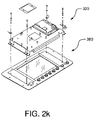
Referring to FIGS. 2 f through 2 n, components of controller 300 are shown in various stages of assembly thereof including top cover 380. Back view of the interior of assembled controller 300 is shown in FIG. 2 n with chassis 390.
According to an exemplary implementation of the present invention, a wireless method of controlling a high voltage power supply utilizing IEEE 802.11 networking can be extended to include the range of products that Hipotronics currently manufacture. Each of these can then be controlled wirelessly. This allows the operator to be completely electrically isolated from the test system to increase safety.
In addition this allows the controller to wirelessly connect to different products, so that a user who needs to perform multiple tests on a part can use the same controller. All of the test results can then be integrated into one test report and sent out to the factory network if needed. Supervisors, mangers or other allowed persons can also then access the system to view progress or view results.
An exemplary implementation of a wireless modular DC hipot controller an regulator for use with portable hipot testers is described below. It is to be noted that according to yet another exemplary implementation, a system according to an embodiment of the present invention may offer a galvanically isolated operating platform for performing hipot tests up to 875 kV DC.
Referring to FIG. 4, controls and indicators according to an exemplary implementation are as follows:
  • 1. Power On/Off 410: Use this control to turn the unit on. The button should be held until the power indicator illuminates. The unit should NOT be turned off using this button, unless the software freezes, in which case holding the button for a period of 10 seconds will cause the unit to shut off. The unit cannot be turned back on after a shutdown, until a period of ten seconds has elapsed.
  • 2. Power Indicator 420: This indicator illuminates when the control unit is turned on.
  • 3. Serial Port 430: RS232 compatible serial port.
  • 4. Software Control Buttons 440: The six buttons are used to select the options displayed on the screen by the software.
  • 5. Rotary Controller 450: This control is used to change fields and values within the software.
  • 6. USB Ports 460: These ports allow USB devices to be attached to the controller to enable data download, keyboard access etc
Referring to FIG. 5, the information being displayed according to an exemplary implementation is as follows:
  • 1. Volt Meter 510: Displays the output voltage in Kilo Volts.
  • 2. Hardware Status 520: This panel shows the status of the regulator. I.e. HVON/OFF, Interlocks etc.
  • 3. Setup Information 530: This panel shows the current information regarding the system setup. It shows the number of DC modules that the system is using, the Max voltage and Current and the Voltage setpoint. Also displayed on this panel is the name of the setup filename that is currently in use.
  • 4. Current Meter 540: Displays the DC output current from the hipot stack. This meter is auto-ranging when the regulator is not raising or lowering, but defaults to the maximum scale during these operations.
  • 5. Timer 550: This meter displays the time that the system has been at the setpoint value, unless the operating mode of the timer is set to ‘manual’ in which case the Start and Stop button will cause the timer to run or stop.
  • 6. Recorder 560: When the high voltage is turned on the chart recorder will be logging. The recorder gives a graphical display of output voltage and current. The recorder will stop recording when HV is turned off.
  • 7. PLC Status 570: All the processing and control within the regulator is carried out by a PLC controller. The message box at the bottom of the screen displays the current status of the PLC program, identifying if the PLC is raising voltage, holding at voltage, or any errors that the PLC has identified.
  • 8. High Voltage Controls 580: These two controls are used to turn the HV on or off in manual operation and start and stop testing during automatic operation.
  • 9. Mode Selection 590: This button toggles the controller-operating mode between manual and automatic.
  • 10. Setup 592: This operator is used to enter the setup and calibration screens.
  • 11. Exit 594: Used to turn off the controller.
Referring to FIGS. 6 a-6 e, control operations according to an exemplary implementation are as follows:
Powering up the Controls: The control unit should be positioned within 50 feet of a Wireless regulator. The AC power to the regulator should be turned to the on position. Hold the ‘Power’ button down on the control unit until the ‘Power Indicator’ is illuminated. The screen on the controller will light up and the internal computer will run through its' ‘boot up’ procedure. Do not turn the power off while the computer is booting. When the computer has finished booting the controller will try to connect to a regulator. (See FIG. 6 a.)
The software is initializing the internal drivers required to communicate with the network. A screen as shown in FIG. 6 a will be present for about 1-2 seconds before it changes to a screen as shown in FIG. 6 b.
The controller is now searching the network to try and locate a compatible regulator device to communicate with. If there is no suitable regulator within range, or the regulator is not yet turned on, then the message as shown in FIG. 6 c will be reported.
The controller will continue to display this message until the power is turned off, or a suitable regulator is brought into range and powered up. When a regulator has been found the message as shown in FIG. 6 d appears.
The screen of FIG. 6 d shows that the controller has successfully connected to an 8175 regulator, which has been identified as ‘ConEdUnit2’. The message box will now go away and the main operation screen will be visible, as shown in FIG. 6 e.
According to an exemplary implementation, before operation it is necessary to ensure that the number of modules displayed on the screen matches the number of modules physically connected in the system. All the settings that affect the normal operation of the system can be adjusted by pressing the Setup button. The screen as shown in FIG. 7 will be displayed where:
    • Number Of Modules: The number of barrels that are being used with the system. This needs to be set for both manual and automatic modes of operation.
    • Ramp Rate: This setting controls the speed of the regulator when raising and lowering. It can be set for Slow, Medium or Fast. In general the setting should be left set to Medium, for high capacitance loads the slow setting may give better results.
    • Timer Mode: When running the controller in ‘Manual’ operating mode the dwell timer can be set to operate either manually or automatically. If the timer is set to manual, then it can be started and stopped at any time, if left in automatic, then the dwell timer will start counting as soon as the selected setpoint is reached and stop when the setpoint is changed, or the HV is turned off.
    • Automatic Test File Name: The name of the settings file that is currently in use. This file contains all the settings from the setup screen. The ‘default’ file is the file that will be used when the unit is first started up. A filename can be assigned to each automatic setup to enable a number of pre-defined test profiles to be stored on the computer.
    • Maximum test voltage: When running an Automatic test this is the voltage at which the hipot test is to be performed.
    • Hold Time: When running in Automatic mode this is the time to hold at the maximum test voltage.
    • Number Of Steps: By selecting the number of steps to greater than one, when an automatic test is run the controller will ramp to the maximum test voltage, but will stop at each step. I.e. if the max test voltage is set to 100 kv and the number of steps is set to ten, the controller will raise the voltage to 10 kV, hold for the time period defined in step hold time and then raise to 20 kV. The tenth step will take the output to 100 kV where the system will dwell for the time defined in the Hold Time field.
    • Step Hold Time: The time that the system will dwell at each step when running an automatic test.
When running a manual test, according to an exemplary implementation, information as shown in FIGS. 8 a and 8 b is displayed. The following procedure may be followed:
    • 1. Ensure that the setup is correct (see above section).
    • 2. Turn on the High Voltage by pressing the ‘HV ON’ button.
    • 3. After the High Voltage has been turned on, the controller reports ‘HV ON Holding at Voltage’. To raise the voltage to the desired level, turn the rotary control to the right until the Voltage Setpoint reads the required voltage level. The controller will raise the output voltage until the setpoint is reached.
    • 4. If the Timer Mode is set to automatic, then the timer will start to run when the output voltage reaches the target voltage. If the timer mode is set to manual, then the operator needs to press the ‘Start Tmr’ button to start the dwell timer running.
    • 5. After the required dwell period, the setpoint should be reduced to zero, by turning the rotary control to the left.
    • 6. Pressing the ‘HV Off’ button turns off the HV.
When running a manual test, according to an exemplary implementation, information as shown in FIG. 9 is displayed. The following procedure may be followed:
    • 1. Select the test profile to be performed by either selecting a file from the setup screen, or by setting up the test using the automatic test parameters in the setup screen.
    • 2. Press the ‘Auto’ button on the main operation screen. The left two buttons at the bottom of the screen will change to ‘Start’ and ‘Stop’. (see FIG. 9).
    • 3. To start the automatic test running, press the ‘start’ button. The hipot will now ramp to the first voltage step, as defined in the setup screen.
    • 4. If the following parameters were set in the setup screen:
Max Test Voltage: 100 kV
Test Time: 30 sec.
Number of steps: 4
Step Hold time: 10 sec.
      • Then the unit will ramp to 25 kV and wait for 10 secs, then raise to 50 kV and hold for 10 seconds, then 75 kV for 10 seconds and finally 100 kV for 30 seconds.
    • 3. After the final test hold time the regulator will lower to zero. It will wait here until the output voltage drops to beneath 5 kV, before turning the HV off. The recorder will record Voltage and current from the moment the HV is turned on to the moment the HV is turned off.
    • 6. If it is required to stop the test at any time, press the ‘Stop’ button. This will turn off the high voltage immediately. All recording functions will also stop at this point.
Numerous additional modifications and variations of the present invention are possible in light of the above teachings. It is therefore to be understood that within the scope of the appended claims, the present invention may be practiced otherwise than as specifically described herein.

Claims (26)

1. A system comprising:
a wireless controller configured to monitor at least one of a current and a voltage;
a first module for sensing first test data indicative of the at least one of the current and the voltage and supporting wireless communication with said wireless controller to provide information comprising said first test data to said wireless controller; and
a power supply which supplies power to said wireless controller;
wherein said wireless communication comprises wireless network communication and communication of first control information from said wireless controller to said module, said first control information comprising first test parameters for sensing said first test data.
2. The system as claimed in claim 1, wherein said wireless controller is galvanically isolated.
3. The system as claimed in claim 1, wherein said wireless communication comprises communication utilizing IEEE 802.11 networking standard.
4. The system as claimed in claim 1, wherein said power supply comprises at least one of a local main supply external to said wireless controller, a portable power source external to said wireless controller, and a battery internal to said wireless controller.
5. The system as claimed in claim 1 further comprising at least a second module for sensing second test data and supporting wireless communication with said wireless controller to provide information comprising said second test data to said wireless controller,
wherein said wireless communication comprises communication of second control information from said wireless controller to said second module, said second control information comprising second test parameters for sensing said second test data.
6. The system as claimed in claim 5, wherein at least one of said first and second modules comprises a unique identifier, and said information provided from said at least one of said first and second modules to said wireless controller comprises said unique identifier.
7. The system as claimed in claim 1 further comprising a supervisory station configured to monitor at least said first test data via said wireless network communication.
8. The system as claimed in claim 1, wherein said first module comprises a number N of modular sections where N is an integer greater than or equal to 1, and said wireless controller has information indicative of the number N of said modular sections.
9. The system as claimed in claim 1, wherein said wireless controller stores at least one test profile comprising a set of test parameters for controlling said first module to sense said first test data.
10. The system as claimed in claim 1, wherein said wireless controller comprises a timer to facilitate control of said first module to sense said first test data at assigned time intervals and/or for an assigned period of time.
11. A wireless controller for high voltage test systems, the wireless controller comprising:
a wireless communication module for wirelessly sending data comprising first control data to a first high voltage testing module and for wirelessly receiving data comprising first test data indicative of at least one of a current and a voltage sensed by said first high voltage testing module, said first control data comprising first test parameters for sensing said first test data;
a display for displaying at least one of said first control data and said first test data;
a user interface for inputting at least a portion of said first control data; and
a connection to a power source;
wherein said wireless communication module is configured for connection to a wireless network.
12. The wireless controller as claimed in claim 11, wherein said wireless controller is galvanically isolated.
13. The wireless controller as claimed in claim 11, wherein said wireless communication module is configured to send at least said first test data to a supervisory station connected to said wireless network.
14. The wireless controller as claimed in claim 11, wherein:
said wireless communication module is further configured to wirelessly send data comprising second control data to a second high voltage testing module and to wirelessly receive data comprising second test data sensed by said second high voltage testing module, said second control data comprising second test parameters for sensing said second test data;
said display is further configured to display at least one of said second control data and said second test data; and
said user interface is further configured for inputting at least a portion of said second control data.
15. The wireless controller as claimed in claim 14, wherein at least one of said first and second high voltage testing modules comprises a unique identifier, and said wireless communication module is configured to associated said data received from at least one of said first and second high voltage testing modules with said unique identifier.
16. The wireless controller as claimed in claim 11, further comprises a storage for storing at least one test profile comprising a set of test parameters for controlling said first high voltage testing module to sense said first test data.
17. The wireless controller as claimed in claim 11, further comprising a timer to facilitate control of said first high voltage testing module to sense said first test data at assigned time intervals and/or for an assigned period of time.
18. A method for controlling a high voltage test system, the method comprising:
establishing a wireless connection between at least a first test module and a wireless controller;
wirelessly sending at least first control data from said wireless controller to at least said first test module; and
wirelessly receiving information comprising at least first test data indicative of at least one of a current and a voltage said first test module;
wherein said wireless connection comprises connection to a wireless network, said first control data comprises first test parameters for controlling said first test module to sense said first test data.
19. The method as claimed in claim 18, further comprising:
establishing a wireless connection between a second test module and said wireless controller;
wirelessly sending second control data from said wireless controller to said second test module; and
wirelessly receiving second test data from said second test module;
wherein said second control data comprises second test parameters for controlling said second test module to sense said second test data.
20. The method as claimed in claim 19, wherein at least one of said first and second test modules comprises a unique identifier, the method further comprising associating said information received from said at least one of said first and second modules with said unique identifier.
21. The method as claimed in claim 18 further comprising supplying power to said wireless controller.
22. The method as claimed in claim 18 further comprising maintaining galvanic isolation of said wireless controller.
23. The method as claimed in claim 18, wherein said first test data is received by said wireless controller, the method further comprising monitoring said first test data from a supervisory station.
24. The method as claimed in claim 18, wherein said first module comprises a number N of modular sections where N is an integer greater than or equal to 1, said method further comprising providing information indicative of the number N of said modular sections to said wireless controller.
25. The method as claimed in claim 18, further comprising storing in said wireless controller at least one test profile comprising a set of test parameters for controlling said first module to sense said first test data.
26. The method as claimed in claim 18, further comprising controlling said first module to sense said test data at assigned time intervals and/or for an assigned period of time.
US11/216,463 2005-09-01 2005-09-01 High-voltage power supply control system and wireless controller and method therefor Active 2027-01-17 US7565253B2 (en)

Priority Applications (3)

Application Number Priority Date Filing Date Title
US11/216,463 US7565253B2 (en) 2005-09-01 2005-09-01 High-voltage power supply control system and wireless controller and method therefor
EP06254429.1A EP1806591B1 (en) 2005-09-01 2006-08-24 High-voltage power supply control system and wireless controller and method therefor
CN2006101118805A CN1975797B (en) 2005-09-01 2006-08-31 High-voltage power supply control system and wireless controller and method therefor

Applications Claiming Priority (1)

Application Number Priority Date Filing Date Title
US11/216,463 US7565253B2 (en) 2005-09-01 2005-09-01 High-voltage power supply control system and wireless controller and method therefor

Publications (2)

Publication Number Publication Date
US20070050159A1 US20070050159A1 (en) 2007-03-01
US7565253B2 true US7565253B2 (en) 2009-07-21

Family

ID=37499619

Family Applications (1)

Application Number Title Priority Date Filing Date
US11/216,463 Active 2027-01-17 US7565253B2 (en) 2005-09-01 2005-09-01 High-voltage power supply control system and wireless controller and method therefor

Country Status (3)

Country Link
US (1) US7565253B2 (en)
EP (1) EP1806591B1 (en)
CN (1) CN1975797B (en)

Cited By (10)

* Cited by examiner, † Cited by third party
Publication number Priority date Publication date Assignee Title
US20090201171A1 (en) * 2008-02-07 2009-08-13 Demartini Paul Small in-home utility services display device
US20090309754A1 (en) * 2008-06-16 2009-12-17 Jimmy Bou Wireless current transformer
US20120086632A1 (en) * 2010-10-11 2012-04-12 Powertech Industrial Co., Ltd. Electric power information user interface, display method and apparatus thereof
RU2511038C2 (en) * 2012-08-02 2014-04-10 Федеральное государственное бюджетное учреждение науки Институт автоматики и процессов управления Дальневосточного отделения Российской академии наук (ИАПУ ДВО РАН) Control method of technical state for high voltage transformer equipment
WO2014071293A1 (en) * 2012-11-05 2014-05-08 Doble Engineering Company Method and apparatus for testing utility power devices
US9002265B2 (en) 2012-07-26 2015-04-07 General Electric Company Method, system and apparatus for galvanic isolation of gate-controlled devices
US9341665B2 (en) 2012-04-18 2016-05-17 Lear Corporation Method and apparatus for high voltage isolation monitor for a vehicle
US20160299175A1 (en) * 2015-04-09 2016-10-13 Fisher-Rosemount Systems, Inc. Method for Supplying Fieldbus Communication and Power from a Handheld Maintenance Tool in a Hazardous Area Using a Single Lead Set
US9874613B2 (en) 2012-11-05 2018-01-23 Doble Engineering Company Method and system of apparatuses for testing utility power devices
CN109188068A (en) * 2018-08-06 2019-01-11 国网山东省电力公司淄博供电公司 Three-stage is U-shaped adjustable to charge installation high-voltage meter

Families Citing this family (9)

* Cited by examiner, † Cited by third party
Publication number Priority date Publication date Assignee Title
US20070094524A1 (en) * 2005-10-25 2007-04-26 Microchip Technology Incorporated Using digital communications in the control of load sharing between paralleled power supplies
GB2456823B (en) * 2008-01-25 2013-07-24 Control Tech Ltd A DC motor drive
CN102625916A (en) * 2009-07-18 2012-08-01 纳克斯伦特有限责任公司 Electrical power system sensor devices, electrical power system monitoring methods, and electrical power system monitoring systems
CN102063877B (en) * 2009-11-12 2013-01-02 群康科技(深圳)有限公司 LCD (Liquid Crystal Display) and detecting method thereof
CN102478638A (en) * 2010-11-27 2012-05-30 西安博昱新能源有限公司 Comprehensive LED streetlamp power source testing system
US10310006B2 (en) 2013-03-15 2019-06-04 Hubbell Incorporated DC high potential insulation breakdown test system and method
CN104635066A (en) * 2015-03-10 2015-05-20 李景禄 Intelligent insulation parameter test residual charge detecting and discharging protection method
CN105355017A (en) * 2015-11-04 2016-02-24 王亲武 Zigbee technology-based intelligent wireless temperature measurement terminal
CN105486894A (en) * 2015-11-27 2016-04-13 国网河南宜阳县供电公司 Unmanned high-voltage metering power distribution device and method

Citations (23)

* Cited by examiner, † Cited by third party
Publication number Priority date Publication date Assignee Title
US3609523A (en) 1969-04-02 1971-09-28 Wayne Electronic Products Co Automatic test apparatus for phase comparison protective relay systems and the like
US3991367A (en) 1976-01-20 1976-11-09 The United States Of America As Represented By The Secretary Of The Interior Detection of potential on high-voltage transmission lines
US4384289A (en) 1981-01-23 1983-05-17 General Electric Company Transponder unit for measuring temperature and current on live transmission lines
US4684887A (en) 1986-06-24 1987-08-04 General Battery Corporation High voltage test confirmation apparatus
US4714893A (en) 1983-04-13 1987-12-22 Niagara Mohawk Power Corporation Apparatus for measuring the potential of a transmission line conductor
US4794327A (en) 1983-04-13 1988-12-27 Fernandes Roosevelt A Electrical parameter sensing module for mounting on and removal from an energized high voltage power conductor
US5136285A (en) 1988-05-20 1992-08-04 Man Design Co., Ltd. Portable data transmitting/receiving apparatus
US5426360A (en) 1994-02-17 1995-06-20 Niagara Mohawk Power Corporation Secondary electrical power line parameter monitoring apparatus and system
US5640155A (en) 1992-02-18 1997-06-17 O'connor Springer Meter cradle with wireless communication port
US5815956A (en) 1996-04-30 1998-10-06 Curtis International , Inc. Vehicle mounting assembly for a snow plow with hidden actuator drive
US6014083A (en) 1996-01-31 2000-01-11 Siemens Aktiengesellschaft Metalclad switchgear assembly with partial discharge detection
US6177884B1 (en) 1998-11-12 2001-01-23 Hunt Technologies, Inc. Integrated power line metering and communication method and apparatus
US6239723B1 (en) 1996-01-31 2001-05-29 Siemens Aktiengesellschaft Encapsulated installation
US20010040446A1 (en) 2000-04-13 2001-11-15 Sterling Lapinksi Apparatus and method for the measurement and monitoring of electrical power generation and transmission
US20030117146A1 (en) 2000-06-26 2003-06-26 Snap-On Technologies, Inc. Alternator testing method and system using timed application of load
US6617840B2 (en) 2001-03-22 2003-09-09 Walter S Bierer Wireless alternating current phasing voltmeter
US6711512B2 (en) 2001-08-07 2004-03-23 Korea Electric Power Data Network Co. Ltd. Pole transformer load monitoring system using wireless internet network
US6778921B2 (en) 2001-04-06 2004-08-17 Eni Technology, Inc. Modular architecture for industrial power delivery system
US20040178918A1 (en) 2002-06-19 2004-09-16 Lockhart Bradley W. Battery monitor
US20040183522A1 (en) 2003-03-19 2004-09-23 Power Measurement Ltd. Power line sensors and systems incorporating same
US20050030693A1 (en) 2004-06-23 2005-02-10 Bela Deak Protective relay test device
US7058524B2 (en) * 2002-10-25 2006-06-06 Hudson Bay Wireless, Llc Electrical power metering system
US7076378B1 (en) * 2002-11-13 2006-07-11 Current Technologies, Llc Device and method for providing power line characteristics and diagnostics

Family Cites Families (7)

* Cited by examiner, † Cited by third party
Publication number Priority date Publication date Assignee Title
CN87209275U (en) * 1987-06-16 1988-07-20 王礼卿 Radio remotecontrolling and protecting unit for microamperemeter
US5136258A (en) 1989-04-28 1992-08-04 Sgs-Thomson Microelectronics S.R.L. Circuit arrangement for enhancing the transconductance of a differential amplifier stage comprising MOS transistors
CN1174365A (en) * 1997-05-22 1998-02-25 张锦雷 Wireless transmission monitoring methed for current parameters of electric power system
CN2396458Y (en) * 1999-07-27 2000-09-13 常州供电局 Power supply unit for high-voltage testing
US6677761B1 (en) * 2001-12-12 2004-01-13 The United States Of America As Represented By The Administrator Of The National Aeronautics And Space Administration Wire insulation defect detector
EP1491903A1 (en) * 2003-05-12 2004-12-29 Kasmatic Innovation A/S Fiberoptic Faraday effect sensor
US7282944B2 (en) 2003-07-25 2007-10-16 Power Measurement, Ltd. Body capacitance electric field powered device for high voltage lines

Patent Citations (23)

* Cited by examiner, † Cited by third party
Publication number Priority date Publication date Assignee Title
US3609523A (en) 1969-04-02 1971-09-28 Wayne Electronic Products Co Automatic test apparatus for phase comparison protective relay systems and the like
US3991367A (en) 1976-01-20 1976-11-09 The United States Of America As Represented By The Secretary Of The Interior Detection of potential on high-voltage transmission lines
US4384289A (en) 1981-01-23 1983-05-17 General Electric Company Transponder unit for measuring temperature and current on live transmission lines
US4714893A (en) 1983-04-13 1987-12-22 Niagara Mohawk Power Corporation Apparatus for measuring the potential of a transmission line conductor
US4794327A (en) 1983-04-13 1988-12-27 Fernandes Roosevelt A Electrical parameter sensing module for mounting on and removal from an energized high voltage power conductor
US4684887A (en) 1986-06-24 1987-08-04 General Battery Corporation High voltage test confirmation apparatus
US5136285A (en) 1988-05-20 1992-08-04 Man Design Co., Ltd. Portable data transmitting/receiving apparatus
US5640155A (en) 1992-02-18 1997-06-17 O'connor Springer Meter cradle with wireless communication port
US5426360A (en) 1994-02-17 1995-06-20 Niagara Mohawk Power Corporation Secondary electrical power line parameter monitoring apparatus and system
US6014083A (en) 1996-01-31 2000-01-11 Siemens Aktiengesellschaft Metalclad switchgear assembly with partial discharge detection
US6239723B1 (en) 1996-01-31 2001-05-29 Siemens Aktiengesellschaft Encapsulated installation
US5815956A (en) 1996-04-30 1998-10-06 Curtis International , Inc. Vehicle mounting assembly for a snow plow with hidden actuator drive
US6177884B1 (en) 1998-11-12 2001-01-23 Hunt Technologies, Inc. Integrated power line metering and communication method and apparatus
US20010040446A1 (en) 2000-04-13 2001-11-15 Sterling Lapinksi Apparatus and method for the measurement and monitoring of electrical power generation and transmission
US20030117146A1 (en) 2000-06-26 2003-06-26 Snap-On Technologies, Inc. Alternator testing method and system using timed application of load
US6617840B2 (en) 2001-03-22 2003-09-09 Walter S Bierer Wireless alternating current phasing voltmeter
US6778921B2 (en) 2001-04-06 2004-08-17 Eni Technology, Inc. Modular architecture for industrial power delivery system
US6711512B2 (en) 2001-08-07 2004-03-23 Korea Electric Power Data Network Co. Ltd. Pole transformer load monitoring system using wireless internet network
US20040178918A1 (en) 2002-06-19 2004-09-16 Lockhart Bradley W. Battery monitor
US7058524B2 (en) * 2002-10-25 2006-06-06 Hudson Bay Wireless, Llc Electrical power metering system
US7076378B1 (en) * 2002-11-13 2006-07-11 Current Technologies, Llc Device and method for providing power line characteristics and diagnostics
US20040183522A1 (en) 2003-03-19 2004-09-23 Power Measurement Ltd. Power line sensors and systems incorporating same
US20050030693A1 (en) 2004-06-23 2005-02-10 Bela Deak Protective relay test device

Cited By (15)

* Cited by examiner, † Cited by third party
Publication number Priority date Publication date Assignee Title
US20090201171A1 (en) * 2008-02-07 2009-08-13 Demartini Paul Small in-home utility services display device
US20090309754A1 (en) * 2008-06-16 2009-12-17 Jimmy Bou Wireless current transformer
US20120086632A1 (en) * 2010-10-11 2012-04-12 Powertech Industrial Co., Ltd. Electric power information user interface, display method and apparatus thereof
US9341665B2 (en) 2012-04-18 2016-05-17 Lear Corporation Method and apparatus for high voltage isolation monitor for a vehicle
US9002265B2 (en) 2012-07-26 2015-04-07 General Electric Company Method, system and apparatus for galvanic isolation of gate-controlled devices
RU2511038C2 (en) * 2012-08-02 2014-04-10 Федеральное государственное бюджетное учреждение науки Институт автоматики и процессов управления Дальневосточного отделения Российской академии наук (ИАПУ ДВО РАН) Control method of technical state for high voltage transformer equipment
WO2014071293A1 (en) * 2012-11-05 2014-05-08 Doble Engineering Company Method and apparatus for testing utility power devices
US9482712B2 (en) 2012-11-05 2016-11-01 Doble Engineering Company Method and apparatus for testing utility power devices
US9632128B2 (en) 2012-11-05 2017-04-25 Doble Engineering Company Method and apparatus for testing utility power devices
US9874613B2 (en) 2012-11-05 2018-01-23 Doble Engineering Company Method and system of apparatuses for testing utility power devices
US20160299175A1 (en) * 2015-04-09 2016-10-13 Fisher-Rosemount Systems, Inc. Method for Supplying Fieldbus Communication and Power from a Handheld Maintenance Tool in a Hazardous Area Using a Single Lead Set
US9709602B2 (en) * 2015-04-09 2017-07-18 Fisher-Rosemount Systems, Inc. Method for supplying fieldbus communication and power from a handheld maintenance tool in a hazardous area using a single lead set
US20170331240A1 (en) * 2015-04-09 2017-11-16 Fisher-Rosemount Systems, Inc. Two-Prong Plug of a Single Lead Set for Supplying Fieldbus Communication and Power from a Handheld Maintenance Tool in a Hazardous Area
US10270215B2 (en) * 2015-04-09 2019-04-23 Fisher-Rosemount Systems, Inc. Two-prong plug of a single lead set for supplying fieldbus communication and power from a handheld maintenance tool in a hazardous area
CN109188068A (en) * 2018-08-06 2019-01-11 国网山东省电力公司淄博供电公司 Three-stage is U-shaped adjustable to charge installation high-voltage meter

Also Published As

Publication number Publication date
CN1975797A (en) 2007-06-06
CN1975797B (en) 2011-06-15
US20070050159A1 (en) 2007-03-01
EP1806591A3 (en) 2012-06-06
EP1806591B1 (en) 2017-09-20
EP1806591A2 (en) 2007-07-11

Similar Documents

Publication Publication Date Title
US7565253B2 (en) High-voltage power supply control system and wireless controller and method therefor
US5744962A (en) Automated data storing battery tester and multimeter
US7209804B2 (en) System and method for providing remote monitoring of voltage power transmission and distribution devices
US20110106280A1 (en) Automated battery scanning, repair, and optimization
US6798209B2 (en) Circuit breaker with integral testing unit
CN1987487B (en) Accessory device voltage management system controlled by a host
US8447543B2 (en) Electric vehicle simulator and analyzer (EVSA) for electric vehicle supply equipment
US5426360A (en) Secondary electrical power line parameter monitoring apparatus and system
US5602750A (en) Administrative computer and testing apparatus
US20050038614A1 (en) Remote battery monitoring systems and sensors
US20110267067A1 (en) Electronic battery tester
CN101978280A (en) Arc fault root-cause finder system and method
WO2006047384A2 (en) Power supply and communications controller
CA2990970A1 (en) Voltage measurement and wireless communication system
US9354256B1 (en) Wirelessly controled circuit tester with building layout information integration and method of use
GB2450426A (en) Circuit breaker electrical power consumption monitoring
KR20080098950A (en) Fire sensing system for distributing electric power
WO2008003917A1 (en) Apparatus for testing wiring
EP1005708B1 (en) Circuit board arrangement
KR20060063829A (en) Test method and device of ratio error test
EP0092303B1 (en) Meter testing device and method
KR100783136B1 (en) Multi Relay Testing Apparatus
CN211263622U (en) Insulation resistance detection device and system
CN106443547A (en) Intelligent insulated earth resistance meter calibrating device
KR20080010175A (en) Battery monitoring system and method for uninterruptible power supply

Legal Events

Date Code Title Description
AS Assignment

Owner name: HUBBELL INCORPORATED, CONNECTICUT

Free format text: ASSIGNMENT OF ASSIGNORS INTEREST;ASSIGNORS:EWERS, CHRISTOPHER F.;SOWERBY, MICHAEL J.;REEL/FRAME:017261/0091;SIGNING DATES FROM 20051103 TO 20051110

FEPP Fee payment procedure

Free format text: PAYOR NUMBER ASSIGNED (ORIGINAL EVENT CODE: ASPN); ENTITY STATUS OF PATENT OWNER: LARGE ENTITY

STCF Information on status: patent grant

Free format text: PATENTED CASE

FPAY Fee payment

Year of fee payment: 4

FPAY Fee payment

Year of fee payment: 8

FEPP Fee payment procedure

Free format text: 11.5 YR SURCHARGE- LATE PMT W/IN 6 MO, LARGE ENTITY (ORIGINAL EVENT CODE: M1556); ENTITY STATUS OF PATENT OWNER: LARGE ENTITY

MAFP Maintenance fee payment

Free format text: PAYMENT OF MAINTENANCE FEE, 12TH YEAR, LARGE ENTITY (ORIGINAL EVENT CODE: M1553); ENTITY STATUS OF PATENT OWNER: LARGE ENTITY

Year of fee payment: 12

FEPP Fee payment procedure

Free format text: MAINTENANCE FEE REMINDER MAILED (ORIGINAL EVENT CODE: REM.); ENTITY STATUS OF PATENT OWNER: LARGE ENTITY