US7534271B2 - Femoral hip prosthesis and method of implantation - Google Patents
Femoral hip prosthesis and method of implantation Download PDFInfo
- Publication number
- US7534271B2 US7534271B2 US10/763,314 US76331404A US7534271B2 US 7534271 B2 US7534271 B2 US 7534271B2 US 76331404 A US76331404 A US 76331404A US 7534271 B2 US7534271 B2 US 7534271B2
- Authority
- US
- United States
- Prior art keywords
- prosthesis
- femoral
- proximal
- elongated stem
- axis
- Prior art date
- Legal status (The legal status is an assumption and is not a legal conclusion. Google has not performed a legal analysis and makes no representation as to the accuracy of the status listed.)
- Expired - Fee Related, expires
Links
Images


Classifications
-
- A—HUMAN NECESSITIES
- A61—MEDICAL OR VETERINARY SCIENCE; HYGIENE
- A61F—FILTERS IMPLANTABLE INTO BLOOD VESSELS; PROSTHESES; DEVICES PROVIDING PATENCY TO, OR PREVENTING COLLAPSING OF, TUBULAR STRUCTURES OF THE BODY, e.g. STENTS; ORTHOPAEDIC, NURSING OR CONTRACEPTIVE DEVICES; FOMENTATION; TREATMENT OR PROTECTION OF EYES OR EARS; BANDAGES, DRESSINGS OR ABSORBENT PADS; FIRST-AID KITS
- A61F2/00—Filters implantable into blood vessels; Prostheses, i.e. artificial substitutes or replacements for parts of the body; Appliances for connecting them with the body; Devices providing patency to, or preventing collapsing of, tubular structures of the body, e.g. stents
- A61F2/02—Prostheses implantable into the body
- A61F2/30—Joints
- A61F2/32—Joints for the hip
- A61F2/36—Femoral heads ; Femoral endoprostheses
- A61F2/3662—Femoral shafts
- A61F2/367—Proximal or metaphyseal parts of shafts
-
- A—HUMAN NECESSITIES
- A61—MEDICAL OR VETERINARY SCIENCE; HYGIENE
- A61F—FILTERS IMPLANTABLE INTO BLOOD VESSELS; PROSTHESES; DEVICES PROVIDING PATENCY TO, OR PREVENTING COLLAPSING OF, TUBULAR STRUCTURES OF THE BODY, e.g. STENTS; ORTHOPAEDIC, NURSING OR CONTRACEPTIVE DEVICES; FOMENTATION; TREATMENT OR PROTECTION OF EYES OR EARS; BANDAGES, DRESSINGS OR ABSORBENT PADS; FIRST-AID KITS
- A61F2/00—Filters implantable into blood vessels; Prostheses, i.e. artificial substitutes or replacements for parts of the body; Appliances for connecting them with the body; Devices providing patency to, or preventing collapsing of, tubular structures of the body, e.g. stents
- A61F2/02—Prostheses implantable into the body
- A61F2/30—Joints
- A61F2/32—Joints for the hip
- A61F2/36—Femoral heads ; Femoral endoprostheses
- A61F2/3662—Femoral shafts
- A61F2/3676—Distal or diaphyseal parts of shafts
-
- A—HUMAN NECESSITIES
- A61—MEDICAL OR VETERINARY SCIENCE; HYGIENE
- A61F—FILTERS IMPLANTABLE INTO BLOOD VESSELS; PROSTHESES; DEVICES PROVIDING PATENCY TO, OR PREVENTING COLLAPSING OF, TUBULAR STRUCTURES OF THE BODY, e.g. STENTS; ORTHOPAEDIC, NURSING OR CONTRACEPTIVE DEVICES; FOMENTATION; TREATMENT OR PROTECTION OF EYES OR EARS; BANDAGES, DRESSINGS OR ABSORBENT PADS; FIRST-AID KITS
- A61F2/00—Filters implantable into blood vessels; Prostheses, i.e. artificial substitutes or replacements for parts of the body; Appliances for connecting them with the body; Devices providing patency to, or preventing collapsing of, tubular structures of the body, e.g. stents
- A61F2/02—Prostheses implantable into the body
- A61F2/30—Joints
- A61F2002/30001—Additional features of subject-matter classified in A61F2/28, A61F2/30 and subgroups thereof
- A61F2002/30003—Material related properties of the prosthesis or of a coating on the prosthesis
- A61F2002/30004—Material related properties of the prosthesis or of a coating on the prosthesis the prosthesis being made from materials having different values of a given property at different locations within the same prosthesis
- A61F2002/30014—Material related properties of the prosthesis or of a coating on the prosthesis the prosthesis being made from materials having different values of a given property at different locations within the same prosthesis differing in elasticity, stiffness or compressibility
-
- A—HUMAN NECESSITIES
- A61—MEDICAL OR VETERINARY SCIENCE; HYGIENE
- A61F—FILTERS IMPLANTABLE INTO BLOOD VESSELS; PROSTHESES; DEVICES PROVIDING PATENCY TO, OR PREVENTING COLLAPSING OF, TUBULAR STRUCTURES OF THE BODY, e.g. STENTS; ORTHOPAEDIC, NURSING OR CONTRACEPTIVE DEVICES; FOMENTATION; TREATMENT OR PROTECTION OF EYES OR EARS; BANDAGES, DRESSINGS OR ABSORBENT PADS; FIRST-AID KITS
- A61F2/00—Filters implantable into blood vessels; Prostheses, i.e. artificial substitutes or replacements for parts of the body; Appliances for connecting them with the body; Devices providing patency to, or preventing collapsing of, tubular structures of the body, e.g. stents
- A61F2/02—Prostheses implantable into the body
- A61F2/30—Joints
- A61F2002/30001—Additional features of subject-matter classified in A61F2/28, A61F2/30 and subgroups thereof
- A61F2002/30108—Shapes
- A61F2002/3011—Cross-sections or two-dimensional shapes
- A61F2002/30112—Rounded shapes, e.g. with rounded corners
- A61F2002/30113—Rounded shapes, e.g. with rounded corners circular
-
- A—HUMAN NECESSITIES
- A61—MEDICAL OR VETERINARY SCIENCE; HYGIENE
- A61F—FILTERS IMPLANTABLE INTO BLOOD VESSELS; PROSTHESES; DEVICES PROVIDING PATENCY TO, OR PREVENTING COLLAPSING OF, TUBULAR STRUCTURES OF THE BODY, e.g. STENTS; ORTHOPAEDIC, NURSING OR CONTRACEPTIVE DEVICES; FOMENTATION; TREATMENT OR PROTECTION OF EYES OR EARS; BANDAGES, DRESSINGS OR ABSORBENT PADS; FIRST-AID KITS
- A61F2/00—Filters implantable into blood vessels; Prostheses, i.e. artificial substitutes or replacements for parts of the body; Appliances for connecting them with the body; Devices providing patency to, or preventing collapsing of, tubular structures of the body, e.g. stents
- A61F2/02—Prostheses implantable into the body
- A61F2/30—Joints
- A61F2002/30001—Additional features of subject-matter classified in A61F2/28, A61F2/30 and subgroups thereof
- A61F2002/30108—Shapes
- A61F2002/3011—Cross-sections or two-dimensional shapes
- A61F2002/30138—Convex polygonal shapes
- A61F2002/30143—Convex polygonal shapes hexagonal
-
- A—HUMAN NECESSITIES
- A61—MEDICAL OR VETERINARY SCIENCE; HYGIENE
- A61F—FILTERS IMPLANTABLE INTO BLOOD VESSELS; PROSTHESES; DEVICES PROVIDING PATENCY TO, OR PREVENTING COLLAPSING OF, TUBULAR STRUCTURES OF THE BODY, e.g. STENTS; ORTHOPAEDIC, NURSING OR CONTRACEPTIVE DEVICES; FOMENTATION; TREATMENT OR PROTECTION OF EYES OR EARS; BANDAGES, DRESSINGS OR ABSORBENT PADS; FIRST-AID KITS
- A61F2/00—Filters implantable into blood vessels; Prostheses, i.e. artificial substitutes or replacements for parts of the body; Appliances for connecting them with the body; Devices providing patency to, or preventing collapsing of, tubular structures of the body, e.g. stents
- A61F2/02—Prostheses implantable into the body
- A61F2/30—Joints
- A61F2002/30001—Additional features of subject-matter classified in A61F2/28, A61F2/30 and subgroups thereof
- A61F2002/30108—Shapes
- A61F2002/3011—Cross-sections or two-dimensional shapes
- A61F2002/30138—Convex polygonal shapes
- A61F2002/30148—Convex polygonal shapes lozenge- or diamond-shaped
-
- A—HUMAN NECESSITIES
- A61—MEDICAL OR VETERINARY SCIENCE; HYGIENE
- A61F—FILTERS IMPLANTABLE INTO BLOOD VESSELS; PROSTHESES; DEVICES PROVIDING PATENCY TO, OR PREVENTING COLLAPSING OF, TUBULAR STRUCTURES OF THE BODY, e.g. STENTS; ORTHOPAEDIC, NURSING OR CONTRACEPTIVE DEVICES; FOMENTATION; TREATMENT OR PROTECTION OF EYES OR EARS; BANDAGES, DRESSINGS OR ABSORBENT PADS; FIRST-AID KITS
- A61F2/00—Filters implantable into blood vessels; Prostheses, i.e. artificial substitutes or replacements for parts of the body; Appliances for connecting them with the body; Devices providing patency to, or preventing collapsing of, tubular structures of the body, e.g. stents
- A61F2/02—Prostheses implantable into the body
- A61F2/30—Joints
- A61F2002/30001—Additional features of subject-matter classified in A61F2/28, A61F2/30 and subgroups thereof
- A61F2002/30108—Shapes
- A61F2002/3011—Cross-sections or two-dimensional shapes
- A61F2002/30138—Convex polygonal shapes
- A61F2002/30153—Convex polygonal shapes rectangular
-
- A—HUMAN NECESSITIES
- A61—MEDICAL OR VETERINARY SCIENCE; HYGIENE
- A61F—FILTERS IMPLANTABLE INTO BLOOD VESSELS; PROSTHESES; DEVICES PROVIDING PATENCY TO, OR PREVENTING COLLAPSING OF, TUBULAR STRUCTURES OF THE BODY, e.g. STENTS; ORTHOPAEDIC, NURSING OR CONTRACEPTIVE DEVICES; FOMENTATION; TREATMENT OR PROTECTION OF EYES OR EARS; BANDAGES, DRESSINGS OR ABSORBENT PADS; FIRST-AID KITS
- A61F2/00—Filters implantable into blood vessels; Prostheses, i.e. artificial substitutes or replacements for parts of the body; Appliances for connecting them with the body; Devices providing patency to, or preventing collapsing of, tubular structures of the body, e.g. stents
- A61F2/02—Prostheses implantable into the body
- A61F2/30—Joints
- A61F2002/30001—Additional features of subject-matter classified in A61F2/28, A61F2/30 and subgroups thereof
- A61F2002/30108—Shapes
- A61F2002/3011—Cross-sections or two-dimensional shapes
- A61F2002/30138—Convex polygonal shapes
- A61F2002/30154—Convex polygonal shapes square
-
- A—HUMAN NECESSITIES
- A61—MEDICAL OR VETERINARY SCIENCE; HYGIENE
- A61F—FILTERS IMPLANTABLE INTO BLOOD VESSELS; PROSTHESES; DEVICES PROVIDING PATENCY TO, OR PREVENTING COLLAPSING OF, TUBULAR STRUCTURES OF THE BODY, e.g. STENTS; ORTHOPAEDIC, NURSING OR CONTRACEPTIVE DEVICES; FOMENTATION; TREATMENT OR PROTECTION OF EYES OR EARS; BANDAGES, DRESSINGS OR ABSORBENT PADS; FIRST-AID KITS
- A61F2/00—Filters implantable into blood vessels; Prostheses, i.e. artificial substitutes or replacements for parts of the body; Appliances for connecting them with the body; Devices providing patency to, or preventing collapsing of, tubular structures of the body, e.g. stents
- A61F2/02—Prostheses implantable into the body
- A61F2/30—Joints
- A61F2002/30001—Additional features of subject-matter classified in A61F2/28, A61F2/30 and subgroups thereof
- A61F2002/30108—Shapes
- A61F2002/3011—Cross-sections or two-dimensional shapes
- A61F2002/30138—Convex polygonal shapes
- A61F2002/30156—Convex polygonal shapes triangular
-
- A—HUMAN NECESSITIES
- A61—MEDICAL OR VETERINARY SCIENCE; HYGIENE
- A61F—FILTERS IMPLANTABLE INTO BLOOD VESSELS; PROSTHESES; DEVICES PROVIDING PATENCY TO, OR PREVENTING COLLAPSING OF, TUBULAR STRUCTURES OF THE BODY, e.g. STENTS; ORTHOPAEDIC, NURSING OR CONTRACEPTIVE DEVICES; FOMENTATION; TREATMENT OR PROTECTION OF EYES OR EARS; BANDAGES, DRESSINGS OR ABSORBENT PADS; FIRST-AID KITS
- A61F2/00—Filters implantable into blood vessels; Prostheses, i.e. artificial substitutes or replacements for parts of the body; Appliances for connecting them with the body; Devices providing patency to, or preventing collapsing of, tubular structures of the body, e.g. stents
- A61F2/02—Prostheses implantable into the body
- A61F2/30—Joints
- A61F2002/30001—Additional features of subject-matter classified in A61F2/28, A61F2/30 and subgroups thereof
- A61F2002/30108—Shapes
- A61F2002/3011—Cross-sections or two-dimensional shapes
- A61F2002/30159—Concave polygonal shapes
- A61F2002/30171—Concave polygonal shapes rosette- or star-shaped
-
- A—HUMAN NECESSITIES
- A61—MEDICAL OR VETERINARY SCIENCE; HYGIENE
- A61F—FILTERS IMPLANTABLE INTO BLOOD VESSELS; PROSTHESES; DEVICES PROVIDING PATENCY TO, OR PREVENTING COLLAPSING OF, TUBULAR STRUCTURES OF THE BODY, e.g. STENTS; ORTHOPAEDIC, NURSING OR CONTRACEPTIVE DEVICES; FOMENTATION; TREATMENT OR PROTECTION OF EYES OR EARS; BANDAGES, DRESSINGS OR ABSORBENT PADS; FIRST-AID KITS
- A61F2/00—Filters implantable into blood vessels; Prostheses, i.e. artificial substitutes or replacements for parts of the body; Appliances for connecting them with the body; Devices providing patency to, or preventing collapsing of, tubular structures of the body, e.g. stents
- A61F2/02—Prostheses implantable into the body
- A61F2/30—Joints
- A61F2002/30001—Additional features of subject-matter classified in A61F2/28, A61F2/30 and subgroups thereof
- A61F2002/30108—Shapes
- A61F2002/30199—Three-dimensional shapes
- A61F2002/30205—Three-dimensional shapes conical
- A61F2002/3021—Three-dimensional shapes conical frustoconical
-
- A—HUMAN NECESSITIES
- A61—MEDICAL OR VETERINARY SCIENCE; HYGIENE
- A61F—FILTERS IMPLANTABLE INTO BLOOD VESSELS; PROSTHESES; DEVICES PROVIDING PATENCY TO, OR PREVENTING COLLAPSING OF, TUBULAR STRUCTURES OF THE BODY, e.g. STENTS; ORTHOPAEDIC, NURSING OR CONTRACEPTIVE DEVICES; FOMENTATION; TREATMENT OR PROTECTION OF EYES OR EARS; BANDAGES, DRESSINGS OR ABSORBENT PADS; FIRST-AID KITS
- A61F2/00—Filters implantable into blood vessels; Prostheses, i.e. artificial substitutes or replacements for parts of the body; Appliances for connecting them with the body; Devices providing patency to, or preventing collapsing of, tubular structures of the body, e.g. stents
- A61F2/02—Prostheses implantable into the body
- A61F2/30—Joints
- A61F2002/30001—Additional features of subject-matter classified in A61F2/28, A61F2/30 and subgroups thereof
- A61F2002/30316—The prosthesis having different structural features at different locations within the same prosthesis; Connections between prosthetic parts; Special structural features of bone or joint prostheses not otherwise provided for
- A61F2002/30317—The prosthesis having different structural features at different locations within the same prosthesis
- A61F2002/30322—The prosthesis having different structural features at different locations within the same prosthesis differing in surface structures
-
- A—HUMAN NECESSITIES
- A61—MEDICAL OR VETERINARY SCIENCE; HYGIENE
- A61F—FILTERS IMPLANTABLE INTO BLOOD VESSELS; PROSTHESES; DEVICES PROVIDING PATENCY TO, OR PREVENTING COLLAPSING OF, TUBULAR STRUCTURES OF THE BODY, e.g. STENTS; ORTHOPAEDIC, NURSING OR CONTRACEPTIVE DEVICES; FOMENTATION; TREATMENT OR PROTECTION OF EYES OR EARS; BANDAGES, DRESSINGS OR ABSORBENT PADS; FIRST-AID KITS
- A61F2/00—Filters implantable into blood vessels; Prostheses, i.e. artificial substitutes or replacements for parts of the body; Appliances for connecting them with the body; Devices providing patency to, or preventing collapsing of, tubular structures of the body, e.g. stents
- A61F2/02—Prostheses implantable into the body
- A61F2/30—Joints
- A61F2002/30001—Additional features of subject-matter classified in A61F2/28, A61F2/30 and subgroups thereof
- A61F2002/30316—The prosthesis having different structural features at different locations within the same prosthesis; Connections between prosthetic parts; Special structural features of bone or joint prostheses not otherwise provided for
- A61F2002/30317—The prosthesis having different structural features at different locations within the same prosthesis
- A61F2002/30327—The prosthesis having different structural features at different locations within the same prosthesis differing in diameter
-
- A—HUMAN NECESSITIES
- A61—MEDICAL OR VETERINARY SCIENCE; HYGIENE
- A61F—FILTERS IMPLANTABLE INTO BLOOD VESSELS; PROSTHESES; DEVICES PROVIDING PATENCY TO, OR PREVENTING COLLAPSING OF, TUBULAR STRUCTURES OF THE BODY, e.g. STENTS; ORTHOPAEDIC, NURSING OR CONTRACEPTIVE DEVICES; FOMENTATION; TREATMENT OR PROTECTION OF EYES OR EARS; BANDAGES, DRESSINGS OR ABSORBENT PADS; FIRST-AID KITS
- A61F2/00—Filters implantable into blood vessels; Prostheses, i.e. artificial substitutes or replacements for parts of the body; Appliances for connecting them with the body; Devices providing patency to, or preventing collapsing of, tubular structures of the body, e.g. stents
- A61F2/02—Prostheses implantable into the body
- A61F2/30—Joints
- A61F2002/30001—Additional features of subject-matter classified in A61F2/28, A61F2/30 and subgroups thereof
- A61F2002/30316—The prosthesis having different structural features at different locations within the same prosthesis; Connections between prosthetic parts; Special structural features of bone or joint prostheses not otherwise provided for
- A61F2002/30329—Connections or couplings between prosthetic parts, e.g. between modular parts; Connecting elements
- A61F2002/30331—Connections or couplings between prosthetic parts, e.g. between modular parts; Connecting elements made by longitudinally pushing a protrusion into a complementarily-shaped recess, e.g. held by friction fit
- A61F2002/30332—Conically- or frustoconically-shaped protrusion and recess
-
- A—HUMAN NECESSITIES
- A61—MEDICAL OR VETERINARY SCIENCE; HYGIENE
- A61F—FILTERS IMPLANTABLE INTO BLOOD VESSELS; PROSTHESES; DEVICES PROVIDING PATENCY TO, OR PREVENTING COLLAPSING OF, TUBULAR STRUCTURES OF THE BODY, e.g. STENTS; ORTHOPAEDIC, NURSING OR CONTRACEPTIVE DEVICES; FOMENTATION; TREATMENT OR PROTECTION OF EYES OR EARS; BANDAGES, DRESSINGS OR ABSORBENT PADS; FIRST-AID KITS
- A61F2/00—Filters implantable into blood vessels; Prostheses, i.e. artificial substitutes or replacements for parts of the body; Appliances for connecting them with the body; Devices providing patency to, or preventing collapsing of, tubular structures of the body, e.g. stents
- A61F2/02—Prostheses implantable into the body
- A61F2/30—Joints
- A61F2002/30001—Additional features of subject-matter classified in A61F2/28, A61F2/30 and subgroups thereof
- A61F2002/30316—The prosthesis having different structural features at different locations within the same prosthesis; Connections between prosthetic parts; Special structural features of bone or joint prostheses not otherwise provided for
- A61F2002/30329—Connections or couplings between prosthetic parts, e.g. between modular parts; Connecting elements
- A61F2002/30331—Connections or couplings between prosthetic parts, e.g. between modular parts; Connecting elements made by longitudinally pushing a protrusion into a complementarily-shaped recess, e.g. held by friction fit
- A61F2002/30354—Cylindrically-shaped protrusion and recess, e.g. cylinder of circular basis
- A61F2002/30357—Stepped cylinders, i.e. having discrete diameter changes
-
- A—HUMAN NECESSITIES
- A61—MEDICAL OR VETERINARY SCIENCE; HYGIENE
- A61F—FILTERS IMPLANTABLE INTO BLOOD VESSELS; PROSTHESES; DEVICES PROVIDING PATENCY TO, OR PREVENTING COLLAPSING OF, TUBULAR STRUCTURES OF THE BODY, e.g. STENTS; ORTHOPAEDIC, NURSING OR CONTRACEPTIVE DEVICES; FOMENTATION; TREATMENT OR PROTECTION OF EYES OR EARS; BANDAGES, DRESSINGS OR ABSORBENT PADS; FIRST-AID KITS
- A61F2/00—Filters implantable into blood vessels; Prostheses, i.e. artificial substitutes or replacements for parts of the body; Appliances for connecting them with the body; Devices providing patency to, or preventing collapsing of, tubular structures of the body, e.g. stents
- A61F2/02—Prostheses implantable into the body
- A61F2/30—Joints
- A61F2002/30001—Additional features of subject-matter classified in A61F2/28, A61F2/30 and subgroups thereof
- A61F2002/30316—The prosthesis having different structural features at different locations within the same prosthesis; Connections between prosthetic parts; Special structural features of bone or joint prostheses not otherwise provided for
- A61F2002/30535—Special structural features of bone or joint prostheses not otherwise provided for
- A61F2002/30594—Special structural features of bone or joint prostheses not otherwise provided for slotted, e.g. radial or meridian slot ending in a polar aperture, non-polar slots, horizontal or arcuate slots
-
- A—HUMAN NECESSITIES
- A61—MEDICAL OR VETERINARY SCIENCE; HYGIENE
- A61F—FILTERS IMPLANTABLE INTO BLOOD VESSELS; PROSTHESES; DEVICES PROVIDING PATENCY TO, OR PREVENTING COLLAPSING OF, TUBULAR STRUCTURES OF THE BODY, e.g. STENTS; ORTHOPAEDIC, NURSING OR CONTRACEPTIVE DEVICES; FOMENTATION; TREATMENT OR PROTECTION OF EYES OR EARS; BANDAGES, DRESSINGS OR ABSORBENT PADS; FIRST-AID KITS
- A61F2/00—Filters implantable into blood vessels; Prostheses, i.e. artificial substitutes or replacements for parts of the body; Appliances for connecting them with the body; Devices providing patency to, or preventing collapsing of, tubular structures of the body, e.g. stents
- A61F2/02—Prostheses implantable into the body
- A61F2/30—Joints
- A61F2/30767—Special external or bone-contacting surface, e.g. coating for improving bone ingrowth
- A61F2/30771—Special external or bone-contacting surface, e.g. coating for improving bone ingrowth applied in original prostheses, e.g. holes or grooves
- A61F2002/3082—Grooves
- A61F2002/30827—Plurality of grooves
-
- A—HUMAN NECESSITIES
- A61—MEDICAL OR VETERINARY SCIENCE; HYGIENE
- A61F—FILTERS IMPLANTABLE INTO BLOOD VESSELS; PROSTHESES; DEVICES PROVIDING PATENCY TO, OR PREVENTING COLLAPSING OF, TUBULAR STRUCTURES OF THE BODY, e.g. STENTS; ORTHOPAEDIC, NURSING OR CONTRACEPTIVE DEVICES; FOMENTATION; TREATMENT OR PROTECTION OF EYES OR EARS; BANDAGES, DRESSINGS OR ABSORBENT PADS; FIRST-AID KITS
- A61F2/00—Filters implantable into blood vessels; Prostheses, i.e. artificial substitutes or replacements for parts of the body; Appliances for connecting them with the body; Devices providing patency to, or preventing collapsing of, tubular structures of the body, e.g. stents
- A61F2/02—Prostheses implantable into the body
- A61F2/30—Joints
- A61F2/30767—Special external or bone-contacting surface, e.g. coating for improving bone ingrowth
- A61F2/30771—Special external or bone-contacting surface, e.g. coating for improving bone ingrowth applied in original prostheses, e.g. holes or grooves
- A61F2002/30878—Special external or bone-contacting surface, e.g. coating for improving bone ingrowth applied in original prostheses, e.g. holes or grooves with non-sharp protrusions, for instance contacting the bone for anchoring, e.g. keels, pegs, pins, posts, shanks, stems, struts
- A61F2002/30879—Ribs
-
- A—HUMAN NECESSITIES
- A61—MEDICAL OR VETERINARY SCIENCE; HYGIENE
- A61F—FILTERS IMPLANTABLE INTO BLOOD VESSELS; PROSTHESES; DEVICES PROVIDING PATENCY TO, OR PREVENTING COLLAPSING OF, TUBULAR STRUCTURES OF THE BODY, e.g. STENTS; ORTHOPAEDIC, NURSING OR CONTRACEPTIVE DEVICES; FOMENTATION; TREATMENT OR PROTECTION OF EYES OR EARS; BANDAGES, DRESSINGS OR ABSORBENT PADS; FIRST-AID KITS
- A61F2/00—Filters implantable into blood vessels; Prostheses, i.e. artificial substitutes or replacements for parts of the body; Appliances for connecting them with the body; Devices providing patency to, or preventing collapsing of, tubular structures of the body, e.g. stents
- A61F2/02—Prostheses implantable into the body
- A61F2/30—Joints
- A61F2/30767—Special external or bone-contacting surface, e.g. coating for improving bone ingrowth
- A61F2/30771—Special external or bone-contacting surface, e.g. coating for improving bone ingrowth applied in original prostheses, e.g. holes or grooves
- A61F2002/30878—Special external or bone-contacting surface, e.g. coating for improving bone ingrowth applied in original prostheses, e.g. holes or grooves with non-sharp protrusions, for instance contacting the bone for anchoring, e.g. keels, pegs, pins, posts, shanks, stems, struts
- A61F2002/30891—Plurality of protrusions
-
- A—HUMAN NECESSITIES
- A61—MEDICAL OR VETERINARY SCIENCE; HYGIENE
- A61F—FILTERS IMPLANTABLE INTO BLOOD VESSELS; PROSTHESES; DEVICES PROVIDING PATENCY TO, OR PREVENTING COLLAPSING OF, TUBULAR STRUCTURES OF THE BODY, e.g. STENTS; ORTHOPAEDIC, NURSING OR CONTRACEPTIVE DEVICES; FOMENTATION; TREATMENT OR PROTECTION OF EYES OR EARS; BANDAGES, DRESSINGS OR ABSORBENT PADS; FIRST-AID KITS
- A61F2/00—Filters implantable into blood vessels; Prostheses, i.e. artificial substitutes or replacements for parts of the body; Appliances for connecting them with the body; Devices providing patency to, or preventing collapsing of, tubular structures of the body, e.g. stents
- A61F2/02—Prostheses implantable into the body
- A61F2/30—Joints
- A61F2/32—Joints for the hip
- A61F2/36—Femoral heads ; Femoral endoprostheses
- A61F2/3609—Femoral heads or necks; Connections of endoprosthetic heads or necks to endoprosthetic femoral shafts
- A61F2002/3611—Heads or epiphyseal parts of femur
-
- A—HUMAN NECESSITIES
- A61—MEDICAL OR VETERINARY SCIENCE; HYGIENE
- A61F—FILTERS IMPLANTABLE INTO BLOOD VESSELS; PROSTHESES; DEVICES PROVIDING PATENCY TO, OR PREVENTING COLLAPSING OF, TUBULAR STRUCTURES OF THE BODY, e.g. STENTS; ORTHOPAEDIC, NURSING OR CONTRACEPTIVE DEVICES; FOMENTATION; TREATMENT OR PROTECTION OF EYES OR EARS; BANDAGES, DRESSINGS OR ABSORBENT PADS; FIRST-AID KITS
- A61F2/00—Filters implantable into blood vessels; Prostheses, i.e. artificial substitutes or replacements for parts of the body; Appliances for connecting them with the body; Devices providing patency to, or preventing collapsing of, tubular structures of the body, e.g. stents
- A61F2/02—Prostheses implantable into the body
- A61F2/30—Joints
- A61F2/32—Joints for the hip
- A61F2/36—Femoral heads ; Femoral endoprostheses
- A61F2/3609—Femoral heads or necks; Connections of endoprosthetic heads or necks to endoprosthetic femoral shafts
- A61F2002/3625—Necks
- A61F2002/3631—Necks with an integral complete or partial peripheral collar or bearing shoulder at its base
-
- A—HUMAN NECESSITIES
- A61—MEDICAL OR VETERINARY SCIENCE; HYGIENE
- A61F—FILTERS IMPLANTABLE INTO BLOOD VESSELS; PROSTHESES; DEVICES PROVIDING PATENCY TO, OR PREVENTING COLLAPSING OF, TUBULAR STRUCTURES OF THE BODY, e.g. STENTS; ORTHOPAEDIC, NURSING OR CONTRACEPTIVE DEVICES; FOMENTATION; TREATMENT OR PROTECTION OF EYES OR EARS; BANDAGES, DRESSINGS OR ABSORBENT PADS; FIRST-AID KITS
- A61F2/00—Filters implantable into blood vessels; Prostheses, i.e. artificial substitutes or replacements for parts of the body; Appliances for connecting them with the body; Devices providing patency to, or preventing collapsing of, tubular structures of the body, e.g. stents
- A61F2/02—Prostheses implantable into the body
- A61F2/30—Joints
- A61F2/32—Joints for the hip
- A61F2/36—Femoral heads ; Femoral endoprostheses
- A61F2/3609—Femoral heads or necks; Connections of endoprosthetic heads or necks to endoprosthetic femoral shafts
- A61F2002/365—Connections of heads to necks
-
- A—HUMAN NECESSITIES
- A61—MEDICAL OR VETERINARY SCIENCE; HYGIENE
- A61F—FILTERS IMPLANTABLE INTO BLOOD VESSELS; PROSTHESES; DEVICES PROVIDING PATENCY TO, OR PREVENTING COLLAPSING OF, TUBULAR STRUCTURES OF THE BODY, e.g. STENTS; ORTHOPAEDIC, NURSING OR CONTRACEPTIVE DEVICES; FOMENTATION; TREATMENT OR PROTECTION OF EYES OR EARS; BANDAGES, DRESSINGS OR ABSORBENT PADS; FIRST-AID KITS
- A61F2220/00—Fixations or connections for prostheses classified in groups A61F2/00 - A61F2/26 or A61F2/82 or A61F9/00 or A61F11/00 or subgroups thereof
- A61F2220/0025—Connections or couplings between prosthetic parts, e.g. between modular parts; Connecting elements
- A61F2220/0033—Connections or couplings between prosthetic parts, e.g. between modular parts; Connecting elements made by longitudinally pushing a protrusion into a complementary-shaped recess, e.g. held by friction fit
-
- A—HUMAN NECESSITIES
- A61—MEDICAL OR VETERINARY SCIENCE; HYGIENE
- A61F—FILTERS IMPLANTABLE INTO BLOOD VESSELS; PROSTHESES; DEVICES PROVIDING PATENCY TO, OR PREVENTING COLLAPSING OF, TUBULAR STRUCTURES OF THE BODY, e.g. STENTS; ORTHOPAEDIC, NURSING OR CONTRACEPTIVE DEVICES; FOMENTATION; TREATMENT OR PROTECTION OF EYES OR EARS; BANDAGES, DRESSINGS OR ABSORBENT PADS; FIRST-AID KITS
- A61F2230/00—Geometry of prostheses classified in groups A61F2/00 - A61F2/26 or A61F2/82 or A61F9/00 or A61F11/00 or subgroups thereof
- A61F2230/0002—Two-dimensional shapes, e.g. cross-sections
- A61F2230/0004—Rounded shapes, e.g. with rounded corners
- A61F2230/0006—Rounded shapes, e.g. with rounded corners circular
-
- A—HUMAN NECESSITIES
- A61—MEDICAL OR VETERINARY SCIENCE; HYGIENE
- A61F—FILTERS IMPLANTABLE INTO BLOOD VESSELS; PROSTHESES; DEVICES PROVIDING PATENCY TO, OR PREVENTING COLLAPSING OF, TUBULAR STRUCTURES OF THE BODY, e.g. STENTS; ORTHOPAEDIC, NURSING OR CONTRACEPTIVE DEVICES; FOMENTATION; TREATMENT OR PROTECTION OF EYES OR EARS; BANDAGES, DRESSINGS OR ABSORBENT PADS; FIRST-AID KITS
- A61F2230/00—Geometry of prostheses classified in groups A61F2/00 - A61F2/26 or A61F2/82 or A61F9/00 or A61F11/00 or subgroups thereof
- A61F2230/0002—Two-dimensional shapes, e.g. cross-sections
- A61F2230/0017—Angular shapes
- A61F2230/0019—Angular shapes rectangular
-
- A—HUMAN NECESSITIES
- A61—MEDICAL OR VETERINARY SCIENCE; HYGIENE
- A61F—FILTERS IMPLANTABLE INTO BLOOD VESSELS; PROSTHESES; DEVICES PROVIDING PATENCY TO, OR PREVENTING COLLAPSING OF, TUBULAR STRUCTURES OF THE BODY, e.g. STENTS; ORTHOPAEDIC, NURSING OR CONTRACEPTIVE DEVICES; FOMENTATION; TREATMENT OR PROTECTION OF EYES OR EARS; BANDAGES, DRESSINGS OR ABSORBENT PADS; FIRST-AID KITS
- A61F2230/00—Geometry of prostheses classified in groups A61F2/00 - A61F2/26 or A61F2/82 or A61F9/00 or A61F11/00 or subgroups thereof
- A61F2230/0002—Two-dimensional shapes, e.g. cross-sections
- A61F2230/0017—Angular shapes
- A61F2230/0021—Angular shapes square
-
- A—HUMAN NECESSITIES
- A61—MEDICAL OR VETERINARY SCIENCE; HYGIENE
- A61F—FILTERS IMPLANTABLE INTO BLOOD VESSELS; PROSTHESES; DEVICES PROVIDING PATENCY TO, OR PREVENTING COLLAPSING OF, TUBULAR STRUCTURES OF THE BODY, e.g. STENTS; ORTHOPAEDIC, NURSING OR CONTRACEPTIVE DEVICES; FOMENTATION; TREATMENT OR PROTECTION OF EYES OR EARS; BANDAGES, DRESSINGS OR ABSORBENT PADS; FIRST-AID KITS
- A61F2230/00—Geometry of prostheses classified in groups A61F2/00 - A61F2/26 or A61F2/82 or A61F9/00 or A61F11/00 or subgroups thereof
- A61F2230/0002—Two-dimensional shapes, e.g. cross-sections
- A61F2230/0017—Angular shapes
- A61F2230/0023—Angular shapes triangular
-
- A—HUMAN NECESSITIES
- A61—MEDICAL OR VETERINARY SCIENCE; HYGIENE
- A61F—FILTERS IMPLANTABLE INTO BLOOD VESSELS; PROSTHESES; DEVICES PROVIDING PATENCY TO, OR PREVENTING COLLAPSING OF, TUBULAR STRUCTURES OF THE BODY, e.g. STENTS; ORTHOPAEDIC, NURSING OR CONTRACEPTIVE DEVICES; FOMENTATION; TREATMENT OR PROTECTION OF EYES OR EARS; BANDAGES, DRESSINGS OR ABSORBENT PADS; FIRST-AID KITS
- A61F2230/00—Geometry of prostheses classified in groups A61F2/00 - A61F2/26 or A61F2/82 or A61F9/00 or A61F11/00 or subgroups thereof
- A61F2230/0002—Two-dimensional shapes, e.g. cross-sections
- A61F2230/0028—Shapes in the form of latin or greek characters
- A61F2230/005—Rosette-shaped, e.g. star-shaped
-
- A—HUMAN NECESSITIES
- A61—MEDICAL OR VETERINARY SCIENCE; HYGIENE
- A61F—FILTERS IMPLANTABLE INTO BLOOD VESSELS; PROSTHESES; DEVICES PROVIDING PATENCY TO, OR PREVENTING COLLAPSING OF, TUBULAR STRUCTURES OF THE BODY, e.g. STENTS; ORTHOPAEDIC, NURSING OR CONTRACEPTIVE DEVICES; FOMENTATION; TREATMENT OR PROTECTION OF EYES OR EARS; BANDAGES, DRESSINGS OR ABSORBENT PADS; FIRST-AID KITS
- A61F2230/00—Geometry of prostheses classified in groups A61F2/00 - A61F2/26 or A61F2/82 or A61F9/00 or A61F11/00 or subgroups thereof
- A61F2230/0063—Three-dimensional shapes
- A61F2230/0067—Three-dimensional shapes conical
-
- A—HUMAN NECESSITIES
- A61—MEDICAL OR VETERINARY SCIENCE; HYGIENE
- A61F—FILTERS IMPLANTABLE INTO BLOOD VESSELS; PROSTHESES; DEVICES PROVIDING PATENCY TO, OR PREVENTING COLLAPSING OF, TUBULAR STRUCTURES OF THE BODY, e.g. STENTS; ORTHOPAEDIC, NURSING OR CONTRACEPTIVE DEVICES; FOMENTATION; TREATMENT OR PROTECTION OF EYES OR EARS; BANDAGES, DRESSINGS OR ABSORBENT PADS; FIRST-AID KITS
- A61F2250/00—Special features of prostheses classified in groups A61F2/00 - A61F2/26 or A61F2/82 or A61F9/00 or A61F11/00 or subgroups thereof
- A61F2250/0014—Special features of prostheses classified in groups A61F2/00 - A61F2/26 or A61F2/82 or A61F9/00 or A61F11/00 or subgroups thereof having different values of a given property or geometrical feature, e.g. mechanical property or material property, at different locations within the same prosthesis
- A61F2250/0026—Special features of prostheses classified in groups A61F2/00 - A61F2/26 or A61F2/82 or A61F9/00 or A61F11/00 or subgroups thereof having different values of a given property or geometrical feature, e.g. mechanical property or material property, at different locations within the same prosthesis differing in surface structures
-
- A—HUMAN NECESSITIES
- A61—MEDICAL OR VETERINARY SCIENCE; HYGIENE
- A61F—FILTERS IMPLANTABLE INTO BLOOD VESSELS; PROSTHESES; DEVICES PROVIDING PATENCY TO, OR PREVENTING COLLAPSING OF, TUBULAR STRUCTURES OF THE BODY, e.g. STENTS; ORTHOPAEDIC, NURSING OR CONTRACEPTIVE DEVICES; FOMENTATION; TREATMENT OR PROTECTION OF EYES OR EARS; BANDAGES, DRESSINGS OR ABSORBENT PADS; FIRST-AID KITS
- A61F2250/00—Special features of prostheses classified in groups A61F2/00 - A61F2/26 or A61F2/82 or A61F9/00 or A61F11/00 or subgroups thereof
- A61F2250/0014—Special features of prostheses classified in groups A61F2/00 - A61F2/26 or A61F2/82 or A61F9/00 or A61F11/00 or subgroups thereof having different values of a given property or geometrical feature, e.g. mechanical property or material property, at different locations within the same prosthesis
- A61F2250/0029—Special features of prostheses classified in groups A61F2/00 - A61F2/26 or A61F2/82 or A61F9/00 or A61F11/00 or subgroups thereof having different values of a given property or geometrical feature, e.g. mechanical property or material property, at different locations within the same prosthesis differing in bending or flexure capacity
-
- A—HUMAN NECESSITIES
- A61—MEDICAL OR VETERINARY SCIENCE; HYGIENE
- A61F—FILTERS IMPLANTABLE INTO BLOOD VESSELS; PROSTHESES; DEVICES PROVIDING PATENCY TO, OR PREVENTING COLLAPSING OF, TUBULAR STRUCTURES OF THE BODY, e.g. STENTS; ORTHOPAEDIC, NURSING OR CONTRACEPTIVE DEVICES; FOMENTATION; TREATMENT OR PROTECTION OF EYES OR EARS; BANDAGES, DRESSINGS OR ABSORBENT PADS; FIRST-AID KITS
- A61F2250/00—Special features of prostheses classified in groups A61F2/00 - A61F2/26 or A61F2/82 or A61F9/00 or A61F11/00 or subgroups thereof
- A61F2250/0014—Special features of prostheses classified in groups A61F2/00 - A61F2/26 or A61F2/82 or A61F9/00 or A61F11/00 or subgroups thereof having different values of a given property or geometrical feature, e.g. mechanical property or material property, at different locations within the same prosthesis
- A61F2250/0039—Special features of prostheses classified in groups A61F2/00 - A61F2/26 or A61F2/82 or A61F9/00 or A61F11/00 or subgroups thereof having different values of a given property or geometrical feature, e.g. mechanical property or material property, at different locations within the same prosthesis differing in diameter
-
- A—HUMAN NECESSITIES
- A61—MEDICAL OR VETERINARY SCIENCE; HYGIENE
- A61F—FILTERS IMPLANTABLE INTO BLOOD VESSELS; PROSTHESES; DEVICES PROVIDING PATENCY TO, OR PREVENTING COLLAPSING OF, TUBULAR STRUCTURES OF THE BODY, e.g. STENTS; ORTHOPAEDIC, NURSING OR CONTRACEPTIVE DEVICES; FOMENTATION; TREATMENT OR PROTECTION OF EYES OR EARS; BANDAGES, DRESSINGS OR ABSORBENT PADS; FIRST-AID KITS
- A61F2310/00—Prostheses classified in A61F2/28 or A61F2/30 - A61F2/44 being constructed from or coated with a particular material
- A61F2310/00005—The prosthesis being constructed from a particular material
- A61F2310/00011—Metals or alloys
- A61F2310/00017—Iron- or Fe-based alloys, e.g. stainless steel
-
- A—HUMAN NECESSITIES
- A61—MEDICAL OR VETERINARY SCIENCE; HYGIENE
- A61F—FILTERS IMPLANTABLE INTO BLOOD VESSELS; PROSTHESES; DEVICES PROVIDING PATENCY TO, OR PREVENTING COLLAPSING OF, TUBULAR STRUCTURES OF THE BODY, e.g. STENTS; ORTHOPAEDIC, NURSING OR CONTRACEPTIVE DEVICES; FOMENTATION; TREATMENT OR PROTECTION OF EYES OR EARS; BANDAGES, DRESSINGS OR ABSORBENT PADS; FIRST-AID KITS
- A61F2310/00—Prostheses classified in A61F2/28 or A61F2/30 - A61F2/44 being constructed from or coated with a particular material
- A61F2310/00005—The prosthesis being constructed from a particular material
- A61F2310/00011—Metals or alloys
- A61F2310/00023—Titanium or titanium-based alloys, e.g. Ti-Ni alloys
-
- A—HUMAN NECESSITIES
- A61—MEDICAL OR VETERINARY SCIENCE; HYGIENE
- A61F—FILTERS IMPLANTABLE INTO BLOOD VESSELS; PROSTHESES; DEVICES PROVIDING PATENCY TO, OR PREVENTING COLLAPSING OF, TUBULAR STRUCTURES OF THE BODY, e.g. STENTS; ORTHOPAEDIC, NURSING OR CONTRACEPTIVE DEVICES; FOMENTATION; TREATMENT OR PROTECTION OF EYES OR EARS; BANDAGES, DRESSINGS OR ABSORBENT PADS; FIRST-AID KITS
- A61F2310/00—Prostheses classified in A61F2/28 or A61F2/30 - A61F2/44 being constructed from or coated with a particular material
- A61F2310/00005—The prosthesis being constructed from a particular material
- A61F2310/00011—Metals or alloys
- A61F2310/00029—Cobalt-based alloys, e.g. Co-Cr alloys or Vitallium
Definitions
- Total hip arthroplasty using a metallic hip prosthesis has been successfully performed since the early 1960's and is now a routine procedure to address orthopedic diseases such as osteoarthritis, fracture, dislocations, rheumatic arthritis, and aseptic or avascular bone necrosis.
- the bone is prepared for the prosthesis by removing the damaged articulating end of the bone by resecting a portion of the bone including the femoral head. This exposes the inside, of the metaphaseal region of the intramedullary canal in the proximal femur. The surgeon then drills or reams a cavity in the femur approximately in line with the intramedullary canal.
- This cavity is used to align other tools such as reamers, broaches and other bone tissue removal instruments to create a roughly funnel shaped bone cavity that is smaller in cross-section as it extends down from the bone resection at the proximal end of the femur into the distal intramedullary canal.
- This funnel shaped cavity is typically also eccentric with more bone material removed from the medial calcar region of the proximal femur than the region on the lateral side of the canal.
- a grouting agent commonly referred to as bone cement is then added to the funnel shaped cavity.
- bone cement is then added to the funnel shaped cavity.
- the shape of the cavity is prepared to closely match the shape of the external surface of the prosthesis, and the prosthesis is press fit into the cavity without the use of bone cement.
- These press-fit prostheses typically have a textured bone-ingrowth surfaces place strategically at specific locations on their surface to help facilitate lone-term bone tissue growth into the prosthesis. This bone ingrowth into the porous structure on the implant creates a long lasting secure bond between the prosthesis and the proximal femur.
- the prosthesis is placed into the bone cavity and is supported directly by internal bone tissue in the case of a press fit implant or indirectly by the bone cement mantle in the case of the cemented implant. Then, the prosthesis is aligned such that the articulating end of the implant articulates with the opposite side of the natural joint in the case of a hemiarthoplasty, or articulates with a corresponding implant replacing the opposite side of the joint in the case of a total joint arthroplasty.
- proximal femur hip prosthesis have eccentric, non-symmetric cone shaped central body portions.
- the current methods of implant fixation allow for transfer of axial loads to the proximal femur mainly through shear stresses at the eccentric funnel shaped bone-prosthesis interface.
- the effective transfer of load is significantly dependent on the three-dimensional shape of funnel shaped cavity, the bone-prosthesis or bone-cement-prosthesis interface as well as physiological loading of the proximal end.
- these currently available prostheses transmit radial expansion forces on the proximal femoral cavity as the implant is loaded in compression.
- the funnel shape of the cavity and the matching shape of the implant or bone cement result in circumferential hoop stresses and radial expansion stresses are distributed to the bone as the femoral component is axially loaded. This results in complex axial and shear stresses at the bone-implant interface. Consequently, the distribution of the loads that transmit from the femoral head axially through the proximal femur is altered after THA.
- a potential cause of failure of currently used prosthesis is associated with the possible resorption of the bone surrounding the implant.
- the bone resorption can be the result of an altered distribution of shear stresses on the remaining proximal femoral tissue.
- the lack of adequate stress transfer from the metal stem to the surrounding bone may cause a loss of bone density, resulting in the increased possibility of bone failure or loosening of the bone-prosthesis interface.
- the gradual loss of bone support in the calcar region of the eccentric cavity increases the bending load that must be borne by the prosthesis. This increase in bending load on the prosthesis can lead to stress shielding by the prosthesis resulting in prosthesis fatigue and potentially to eventual clinical failure.
- the flange portion is distal and adjacent to the neck portion and is attached to the distal neck body.
- the flange portion comprises an upper portion and a bottom surface.
- the transitional body region is adjacent to the bottom surface of the flange portion and also extends from the distal neck body.
- the elongated stem portion extends distally from the transitional body region and is aligned with a longitudinal axis.
- the longitudinal axis is oriented at an acute angle relative to the bottom surface of the flange portion.
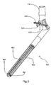
- the elongated stem portion comprises a uniform envelope that may contain rotation-restricting splines, a tapered portion or a transverse slot.
- the femoral hip prosthesis may also alternatively contain a rotation-restricting boss that is attached to the bottom of the flange portion.
- the femoral hip prosthesis also comprises a distal end tip portion on the distal end of the elongated stem portion.
- FIG. 1 is a perspective view of the show from the anteriomedial direction showing the femoral hip prosthesis including the before it is inserted into the resected proximal femur;
- FIG. 2 is a perspective view shown form the anterioromedial direction showing the femoral hip prostheses before it is inserted and a cross-sectional view of the resected proximal femur with the intramedullary cavity and the boss cavity prepared;
- FIG. 4 is an anterior side view of the femoral hip prosthesis shown outside of the femur;
- FIG. 4 a is an embodiment of a substantially circular cross-section of the elongated stem portion
- FIG. 4 b is an embodiment of a substantially square cross-section of the elongated stem portion
- FIG. 4 c is an embodiment of a substantially triangular cross-section of the elongated stem portion
- FIG. 4 e is an embodiment of a substantially star shaped cross-section of the elongated stem portion
- FIG. 7 is a medial view of the femoral hip prosthesis inside of the proximal femur.
- FIGS. 1 through 7 Depicted in FIGS. 1 through 7 are different embodiments of an implantable proximal femoral hip prosthesis 50 and methods of implantation therein. These embodiments of a hip joint replacement procedure and the design of the femoral hip prosthesis 50 that is meant to restore the biomechanical function of the hip joint while maintaining a secure interface with the proximal femur 10 and help to preserve anatomical loading of the remaining bone that surrounds the femoral hip prosthesis 50 once it is implanted. This allows the loads on the hip joint to be distributed optimally to the proximal femur 10 .
- the femoral hip prosthesis 50 comprises a femoral head component 700 and a femoral stem component 100 .
- the femoral stem component 100 comprises a neck portion 150 , a flange portion 200 , a transitional body portion 300 , an elongated stem portion 400 , and a distal tip end 500 .
- the non-eccentric symmetrical shape of the interface between the elongated stem portion 400 of the femoral stem component 100 and a cavity 25 along with the contact at the interface between a proximal resection 20 and the femoral stem component 100 helps to stabilize the femoral hip prosthesis 50 and transfer more anatomic loads from the prosthesis 50 to the bone efficiently.
- FIG. 1 is a simplified perspective view from the anteriomedial direction showing the proximal femur 10 and the femoral hip prosthesis 50 , showing the femoral head component 700 , the femoral stem component 100 , and the proximal femur 10 .
- the femoral head component 700 shows the femoral head component 700 .
- the femoral stem component 100 shows the proximal femur 10 .
- all of the other tissues necessary to provide function to the hip joint are not shown in this simplified view.
- the surgeon aligns bone tissue removal tools, such as drills, reamers, or broaches (not shown) with alignment instrumentation (not shown) to form a substantially non-eccentric, symmetric intramedullary cavity 25 in the cancellous bone 3 of the proximal femur 10 that is in longitudinal alignment with the shaft 45 of the proximal femur 10 .
- the intramedullary cavity 25 is formed with a cross-sectional shape, such as a diameter 46 as shown in an embodiment of the intramedullary cavity 25 shown in FIG. 2 .
- the diameter 46 is the measurement of the diameter of the maximum circular periphery that encompasses an envelope that the cross-sectional shape of the intramedullary cavity 25 comprises.
- the shape of the intramedullary cavity 25 can also be substantially non-eccentric, symmetric, non-circular shapes such as a square (not shown), star shape, (not shown), hexagon (not shown), or other parallelogram shape. Matching non-circular shapes of both the femoral stem component 100 and the intramedullary cavity 25 are potentially more efficient at restricting torsional movement between the femoral stem component 100 and the proximal femur 10 than circular cross-sectional shapes.
- the intramedullary cavity 25 also is formed to a length 47 as also shown in FIG. 2 .
- the cross-sectional shape, diameter 46 and length 47 of the intramedullary cavity 25 in the proximal femur 10 is dependent on the morphology, structure, and pathology of the patient anatomy and the anticipated biomechanical in vivo loads resulting from the use of the femoral stem component 100 .
- the cavities 2 are circular, resulting in a substantially cylindrical opening.
- different size or shaped tissue removal tools (not shown) are used to prepare an intramedullary cavity 25 with more than one size diameter 46 .
- the surgeon may also find it advantageous to form different or alternating shapes of cross-sections in the symmetric, non-eccentric intramedullary cavity 25 .
- the cavity may be first diameter circular, and then square, then a second diameter circle, then a star shape, then cone shaped, then finally spherically shaped at its deepest, most distal end.
- proximal resection 20 may be simply one continuous transverse cut that passes from the medial to the lateral side of the proximal femur in the direction and plane defined by a the plane outlined by the dashed line 16 shown in FIG. 1 .
- This alternative resection 17 is formed by extending the calcar resection 12 from medial to lateral though the entire proximal femur 10 .
- More bone conserving cuts may also be formed in to the proximal femur 10 as shown in FIG. 1 .
- These cuts may include a formed concentric region 15 that is larger in size but concentric to or aligned with the intramedullary cavity 25 .
- These cuts may also include a transverse resection 13 that is cut relatively perpendicular to the intramedullary cavity 25 .
- the resections shown in FIG. 1 can all be formed by a single reamer (not shown). This reamer has a cutting surface formed in the shape of the combined profile of all of the resection cuts. It can be rotated or oscillated about the longitudinal axis 21 of the intramedullary canal 25 , until the desire bone tissue is removed.
- the various cuts that together form the proximal resection 20 pass through portions of both the relatively dense cortical bone 44 and the more porous cancellous bone 3 .
- the cutting surfaces of the tissue removal tools are designed to cut both dense cortical bone 44 and less dense cancellous bone 3 .
- the femoral stem component 100 has a proximal male friction fit portion 150 on its most proximal end that is shaped to accept partially hemispherical femoral head component 700 .
- One shape of the proximal male friction fit portion 150 is a cylindrical taper shape with the smaller diameter on the male friction fit portion proximal section 151 , a tapered male friction fit portion 152 distal to the male friction fit portion proximal section 151 , and a larger diameter male friction fit portion taper maximum cross-section bottom end 153 on the distal end of the male friction fit portion 152 .
- the proximal male friction fit portion 150 could also be a straight cylindrical shape without a taper, or a series of successively larger diameter cylindrical shapes.
- a femoral head component 700 has a male cavity 720 that is dimensioned to fit over and mate with the friction fit portion 152 of the proximal male friction fit portion 150 when the femoral head component 700 is assembled on the proximal male friction fit portion 150 .
- the femoral head prosthesis 700 has an external bearing surface portion 710 on its external surface that is substantially on its proximal side when implanted.
- the external bearing surface portion 710 of the femoral head prosthesis 700 is substantially hemispherical shaped on a portion of its load bearing external bearing surface.
- the proximal male friction fit portion 150 has a male friction fit portion neck 154 that is distal to the male friction fit portion portion 152 and adjacent to the male friction fit portion taper bottom end 153 .
- This male friction fit portion neck 154 functions as an undercut relief for the femoral head component 700 when assembled. Because the male friction fit portion neck 154 is smaller in diameter than the male friction fit portion portion 152 , the femoral head component 700 can be pressed onto the proximal male friction fit portion 150 with the only direct contact between the two on the friction fit portion 152 of the femoral stem component 100 and the male friction fit portion 720 of the femoral head component 700 .
- the male friction fit portion neck 154 is proximal to and attached directly to a more bulky distal neck body 160 .
- the distal neck body 160 is shaped to distribute the loads transmitted through the proximal male friction fit portion 150 from the femoral head component 700 through a flange portion 200 and a transitional body portion 300 .
- the shape of the distal neck body 160 transitions from a simple symmetric shape similar to the cross-section of the male friction fit portion neck 154 to a more complex asymmetric shape that is similar to the combined shape of the flange portion 200 and the transitional body portion 300 . In the embodiment shown in FIGS. 1 through FIG.
- the cross-sectional shape of the distal neck body 160 at the proximal section is round because the male friction fit portion is a conical tapered and the male friction fit portion neck 154 is a cylindrical hourglass shape.
- the shape of the distal neck body 160 at the proximal section can be other shape to correspond with the shape of the proximal male friction fit portion 150 .
- the flange portion 200 has an upper portion 210 on its proximal side that contacts at least a part of the distal neck body 160 .
- the flange portion is angled to match the at the same angle as the calcar resection 12 made by the surgeon on the proximal femur 10 .
- the angle and the size of the flange portion 200 are dependent on the anatomy of the patient and the morphology of the calcar resection 12 .
- the flange portion 200 has an anterior-posterior flange portion width 240 that is wide enough to cover at least a portion of the cortical bone tissue 44 that has been resected.
- the cortical bone tissue 44 is more rigid than the cancellous bone tissue 3 .
- the compressive loads are transmitted through both the cancellous bone tissue and the cortical bone tissue 44 of the proximal femur 10 . Because the cortical bone tissue 44 is more dense and rigid, and can sustain a higher load per square unit area without fracture than the cancellous bone tissue 3 , cortical bone tissue 44 is a more efficient distributor of compressive loads than cancellous bone tissue 3 .
- the transitional body portion 300 has a curved fillet 330 its medial side. Although this is shown as a round fillet in FIG. 4 , the medial side of the transitional body portion 300 can be a chamfered fillet, a stepped fillet, or any other non-linear or linear shape that transitions from the shape of the elongated stem portion 400 to the shape of portions of the distal neck body 160 or the flange portion 200 .
- the maximum height 310 of the majority of the transitional body region 300 when measured normal from the bottom surface 220 of the flange portion 200 to any part of the elongated stem portion 400 is less than thirteen millimeters or less. Both the physical structure of the femoral hip prosthesis 50 , and the mechanical properties of the material from which the prosthesis is fabricated, function together to determine the functional strength and elasticity of the femoral stem component 100 .
- Conventional orthopedic alloys such as cobalt chrome, titanium and stainless steel alloys and orthopedic composite materials have proven to provide reasonable strength and rigidity to orthopedic implants and may also be used to fabricate the femoral stem component 100 .
- conventional orthopedic alloys or composites are fabricated into the eccentric conical shape of a typical femoral stem component 100 , the resulting implant is more rigid than the proximal femoral 10 that the femoral stem component 100 is replacing. Flexibility of the stem component 100 is necessary to allow the flex and compliance desired to dynamically anatomically load the proximal femur 10 bone during biomechanical loading.
- This dynamic flexibility within the transitional portion 300 is desired since it allows the flange portion 200 of the femoral stem component 100 to transmit loads and displacements to the femoral calcar region 11 of the proximal femur 10 .
- a piezoelectric effect within the tissue simulate the bone cells into further production.
- This phenomenon sometimes called Wolfs Law, coupled with other physiologic and biochemical principles, helps to keep the bone surrounding the femoral hip prosthesis 50 healthy and vibrant.
- the femoral stem component 100 is designed to optimize the effects that a flexible, yet strong femoral hip prosthesis 50 will have on the surrounding loaded bone tissue.
- the elongated stem portion 400 is longitudinally aligned with a longitudinal axis 425 .
- the longitudinal axis 425 is approximately in alignment with the longitudinal axis 21 of the intramedullary cavity 25 .
- All the possible features or portions of the elongated stem portion 400 including the tapered portion 450 , the spine section 470 , and the transverse slot 480 have cross-sections perpendicular to the longitudinal axis 425 and are contained within a maximum diameter 905 of a cross-sectional periphery 902 that defines the cross-section of the uniform envelope 410 .
- the cross-sectional shape of the elongated stem portion 400 can be also non-circular shapes such as substantially square shape 920 , as shown in FIG. 4 b; a substantially triangle shape 930 , as shown in FIG. 4 c; a substantially hexagonal shape 940 , as shown in FIG. 4 c, a substantially star shape 950 as shown in FIG. 4 e, or any other substantially non-eccentric, symmetric shape such as a tube (not shown) that can functionally form the cross-section of the elongated stem portion 400 .
- the longitudinal axis 425 of the elongated stem portion 400 is a substantially straight axis throughout the length of the elongated stem portion 400 .
- the longitudinal axis 425 can also be curved.
- the curve may be in the anterior-posterior plane, the medial-lateral plane or a compound curve that is seen in both the anterior-posterior plane and the medial-lateral plane.
- a flexible reamer (not shown) could be used to form the curved intramedullary cavity before the prosthesis 10 with a curved longitudinal axis 425 is implanted.
- the tapered portion 450 also allows for an interference tapered wedge fit between the elongated stem portion 400 and the intramedullary cavity 25 in the proximal femur 10 when the cross-sectional size of the intramedullary canal 25 is less than the maximum diameter 905 of the periphery 902 .
- the splines 460 are cut into the elongated stem portion 400 for various structural and functional reasons such as to provide additional torsional resistance to the femoral stem component 100 .
- the splines 460 are evenly spaced around the periphery 902 of the distal elongated stem portion 400 .
- the splines 460 are cut longitudinal around the periphery 902 of the elongated stem portion 400 . This allows the splines 460 to resist axial rotation between the femoral stem component 100 and the intramedullary cavity 25 .
- the splines 460 may also provide additional structural flexibility to the distal end of the femoral stem component 100 .
- an optional longitudinal transverse slot 480 may be cut transversely into the elongated stem portion 400 to provide additional flexibility and potentially additional torsional resistance to the femoral stem component 100 .
- the embodiment of the slot 480 that is shown is substantially uniform in cross-sectional and in shape though its length.
- the cross-sectional shape of the slot 480 may also be non-uniform.
- the cross-sections shape of the slot 480 may also change. For example the sides of the slot 481 may change from parallel planar surfaces to non-parallel or non-planar surfaces as the slot transitions from distal to proximal.
- the slot 480 also has a fillet 485 that takes the form of a rounded radius shape at its most proximal end.
- the shape of this fillet 485 may be other shapes that allow a relatively smooth transition from the slot 480 to the non-slotted cross-section.
- the slot 480 may be keyhole shaped.
- the distal end tip portion 500 Adjacent and distal to the elongated stem portion is the distal end tip portion 500 .
- the distal end tip portion 500 has a lead-in section 510 that reduces in cross-sectional area from proximal to distal.
- the lead-in section may be tapered as in the embodiment of FIG. 3 , or spherical as in the embodiment of FIG. 4 , or any shape that is successively smaller in cross-sectional area from proximal to distal.
- the distal end tip portion 500 helps to guide the femoral stem component 100 into the intramedullary canal 25 .
- the relatively smooth shape of the distal end tip portion 500 also functions to reduce the stress on the proximal femoral bone associated with discontinuity of terminating a rigid prosthesis in the intramedullary canal 25 .
- the load distribution on the proximal femur 10 of an intact hip joint can be essentially resolved into an axial component, a bending moment in the medial and lateral direction, a bending moment in the anterior posterior direction, and a torsional moment with a rotational axis approximately in line with the longitudinal axis 21 of the proximal femur.
- the distribution of the magnitude and direction of these force components depend upon complex combinations of biomechanical factors such as leg stance, patient weight distribution, and patient gait.
- the femoral stem component 100 is designed to translate these forces to anatomic loads on the proximal femur 10 .
- the flange portion 200 helps to translate the compressive loads to the cancellous bone 3 and cortical bone 4 in the calcar region 11 .
- the elongated stem portion 400 helps to transmit the bending and torsional moments to the intramedullary canal 25 .
- a rotation-restricting boss 600 helps to transmit some of the torsional moments to the bone in the calcar region 11 of the proximal femur 10 . As shown in FIG. 6 , the boss periphery 630 of the rotation-restricting boss 600 interfaces with the bone surrounding the boss cavity 14 .
- This structural interference between the femoral stem component 100 and the proximal femur 10 helps to restrict rotation, caused by the above-described resultant torsional moment with approximately in line with the longitudinal axis 21 of the proximal femur 10 , between the femoral stem component 100 and the intramedullary cavity 25 .
- the size and location of the rotation-restricting boss 600 are factors that affect the amount that the rotation-restricting boss 600 restricts rotational movement of the femoral stem component 100 . Due to greater resistance from a rotation-restricting boss with a larger resultant moment arm, the further that the rotation-restricting boss 600 is located from the longitudinal axis 425 of the elongated stem portion 400 , the more effective it is in transmitting rotational loads and restricting rotational movement of the femoral stem component 100 to the proximal femur 10 . Also, the larger the cross-sectional area of the rotation-restricting boss 600 , the more effective it is in distributing torsion and restricting rotational movement of the femoral stem component 100 .
- the embodiments of the rotation-restricting boss 600 that are shown by example are circular in cross-section resulting in a cylindrical shaped boss.
- other cross-sectional shapes such as square, rectangular, triangular or diamond shapes may be more practical to machine or may be better at distributing torsional loads from the femoral hip prosthesis 50 to the proximal femur 10 than the shown cylindrically shaped rotation-restricting boss 600 .
- the optimized shape of the rotation-restricting boss 600 may be more fin shaped than cylindrical shaped or longer than it is wide. This shape is partially dependent on the mechanical characteristics of the bone tissue where the rotation-restricing boss 600 is inserted.
- the rotation restricting boss 600 has an axis of protrusion 620 with origin 621 substantially on a plane tangent or coincident with the bottom surface 220 of the flange portion 200 .
- the boss axis of protrusion origin 621 and the stem portion longitudinal axis 425 are spaced apart by a length this is more than the maximum length 905 of the cross-section of the periphery 902 of the uniform envelope 410 of the elongated stem portion 400 .
- the rotation-restricting boss 600 in the embodiment of the prosthesis 10 shown in FIG. 3 has an axis of protrusion that is substantially normal to the bottom surface 220 of the flange portion 200 .
- the rotation-restricting boss in the embodiment of the prosthesis 10 shown in FIG. 4 , FIG. 5 and FIG. 6 has an axis of protrusion 620 that is substantially parallel with the longitudinal axis 425 of the elongated stem portion 400 .
- the corresponding boss cavity 14 is in line with the axis of protrusion 620 .
- the flange portion 200 is pressed against a resected surface 20 on the proximal femur 10 , and the elongated stem portion 400 is pressed in the intramedullary cavity 25 aligned with the long axis of the proximal femur 10 .
- the femoral head 700 is loaded by the hip joint, a substantial component of the axial compressive force is transmitted to the cancellous 3 and cortical 4 bone in the calar region 11 from the flange portion 200 .
Abstract
Description
Claims (20)
Priority Applications (9)
| Application Number | Priority Date | Filing Date | Title |
|---|---|---|---|
| US10/763,314 US7534271B2 (en) | 2004-01-22 | 2004-01-22 | Femoral hip prosthesis and method of implantation |
| EP05711398A EP1718250A4 (en) | 2004-01-22 | 2005-01-10 | Femoral hip prosthesis and method of implantation |
| JP2006551156A JP4838731B2 (en) | 2004-01-22 | 2005-01-10 | Femoral hip prosthesis and transplantation method |
| PCT/US2005/001046 WO2005069810A2 (en) | 2004-01-22 | 2005-01-10 | Femoral hip prosthesis and method of implantation |
| AU2005206852A AU2005206852A1 (en) | 2004-01-22 | 2005-01-10 | Femoral hip prosthesis and method of implantation |
| CA002554148A CA2554148A1 (en) | 2004-01-22 | 2005-01-10 | Femoral hip prosthesis and method of implantation |
| US11/351,621 US7374576B1 (en) | 2004-01-22 | 2006-02-09 | Polyaxial orthopedic fastening apparatus with independent locking modes |
| US12/429,882 US20090216335A1 (en) | 2004-01-22 | 2009-04-24 | Femoral Hip Prosthesis and Method of Implantation |
| US12/882,399 US8157871B2 (en) | 2004-01-22 | 2010-09-15 | Femoral HIP prosthesis and method of implantation |
Applications Claiming Priority (1)
| Application Number | Priority Date | Filing Date | Title |
|---|---|---|---|
| US10/763,314 US7534271B2 (en) | 2004-01-22 | 2004-01-22 | Femoral hip prosthesis and method of implantation |
Related Child Applications (2)
| Application Number | Title | Priority Date | Filing Date |
|---|---|---|---|
| US11/351,621 Division US7374576B1 (en) | 2004-01-22 | 2006-02-09 | Polyaxial orthopedic fastening apparatus with independent locking modes |
| US12/429,882 Continuation US20090216335A1 (en) | 2004-01-22 | 2009-04-24 | Femoral Hip Prosthesis and Method of Implantation |
Publications (2)
| Publication Number | Publication Date |
|---|---|
| US20050165493A1 US20050165493A1 (en) | 2005-07-28 |
| US7534271B2 true US7534271B2 (en) | 2009-05-19 |
Family
ID=34795014
Family Applications (4)
| Application Number | Title | Priority Date | Filing Date |
|---|---|---|---|
| US10/763,314 Expired - Fee Related US7534271B2 (en) | 2004-01-22 | 2004-01-22 | Femoral hip prosthesis and method of implantation |
| US11/351,621 Expired - Fee Related US7374576B1 (en) | 2004-01-22 | 2006-02-09 | Polyaxial orthopedic fastening apparatus with independent locking modes |
| US12/429,882 Abandoned US20090216335A1 (en) | 2004-01-22 | 2009-04-24 | Femoral Hip Prosthesis and Method of Implantation |
| US12/882,399 Expired - Fee Related US8157871B2 (en) | 2004-01-22 | 2010-09-15 | Femoral HIP prosthesis and method of implantation |
Family Applications After (3)
| Application Number | Title | Priority Date | Filing Date |
|---|---|---|---|
| US11/351,621 Expired - Fee Related US7374576B1 (en) | 2004-01-22 | 2006-02-09 | Polyaxial orthopedic fastening apparatus with independent locking modes |
| US12/429,882 Abandoned US20090216335A1 (en) | 2004-01-22 | 2009-04-24 | Femoral Hip Prosthesis and Method of Implantation |
| US12/882,399 Expired - Fee Related US8157871B2 (en) | 2004-01-22 | 2010-09-15 | Femoral HIP prosthesis and method of implantation |
Country Status (6)
| Country | Link |
|---|---|
| US (4) | US7534271B2 (en) |
| EP (1) | EP1718250A4 (en) |
| JP (1) | JP4838731B2 (en) |
| AU (1) | AU2005206852A1 (en) |
| CA (1) | CA2554148A1 (en) |
| WO (1) | WO2005069810A2 (en) |
Cited By (13)
| Publication number | Priority date | Publication date | Assignee | Title |
|---|---|---|---|---|
| US20060217814A1 (en) * | 2002-09-13 | 2006-09-28 | Smith & Nephew, Inc. | Hip prostheses |
| US20080228283A1 (en) * | 2004-07-17 | 2008-09-18 | Zimmer Gmbh | Femur component for a hip joint prosthesis |
| US20080281430A1 (en) * | 2005-02-22 | 2008-11-13 | Kelman David C | Long Sleeves for Use with Stems |
| US20090018546A1 (en) * | 2007-07-11 | 2009-01-15 | Daley Robert J | Methods and apparatus for determining pin placement during hip surgery |
| US20090216335A1 (en) * | 2004-01-22 | 2009-08-27 | Smith & Nephew | Femoral Hip Prosthesis and Method of Implantation |
| US20130096690A1 (en) * | 2011-10-17 | 2013-04-18 | Thomas Hatton McCoy | Anterior offset component for total hip replacement |
| US8840676B2 (en) | 2009-05-07 | 2014-09-23 | Smith & Nephew, Inc. | Modular trial heads for a prosthetic |
| US8992531B2 (en) | 2011-12-16 | 2015-03-31 | Chow Ip, Llc | Prosthetic femoral stem for use in high impact hip replacement |
| US9301765B2 (en) | 2011-12-16 | 2016-04-05 | Chow Ip, Llc | Prosthetic femoral stem for use in high offset hip replacement |
| US9345576B2 (en) | 2011-12-07 | 2016-05-24 | Smith & Nephew, Inc. | Orthopedic augments having recessed pockets |
| US9439781B2 (en) | 2011-05-03 | 2016-09-13 | Smith & Nephew, Inc. | Patient-matched guides for orthopedic implants |
| US9707097B2 (en) | 2011-12-07 | 2017-07-18 | Smith & Nephew, Inc. | Orthopedic implant augments |
| US9901451B2 (en) | 2010-06-08 | 2018-02-27 | Smith & Nephew, Inc. | Implant components and methods |
Families Citing this family (25)
| Publication number | Priority date | Publication date | Assignee | Title |
|---|---|---|---|---|
| US6592996B1 (en) | 1998-02-06 | 2003-07-15 | Nippon Sheet Glass Co., Ltd. | Solar-shading light-transmissive panel and solar-shading multi-layer light-transmissive panel using same |
| GB0207170D0 (en) * | 2002-03-26 | 2002-05-08 | Mcminn Derek J W | Hip joint prosthesis |
| US7842096B2 (en) * | 2005-02-22 | 2010-11-30 | Zimmer Technology, Inc. | Hip stem prosthesis |
| AU2007299711A1 (en) * | 2006-09-20 | 2008-03-27 | Smith & Nephew, Inc. | Variable stiffness stem for prosthetic implants |
| US20100125303A1 (en) * | 2008-11-20 | 2010-05-20 | Daley Robert J | Methods and apparatus for replacing biological joints using bone mineral substance in a suspended state |
| US20100125335A1 (en) * | 2008-11-20 | 2010-05-20 | Daley Robert J | Methods and apparatus for replacing biological joints using bone cement in a suspended state |
| EP2710982B1 (en) * | 2012-09-21 | 2016-08-31 | WALDEMAR LINK GmbH & Co. KG | Joint implant |
| CN103445885B (en) * | 2013-07-02 | 2015-05-13 | 刘顺民 | Femoral handle fixed through expansion |
| CA2945830C (en) * | 2014-04-16 | 2022-08-09 | Osseointegration Holdings Pty Ltd | An osseointegrable device |
| TWI634881B (en) * | 2015-04-21 | 2018-09-11 | 寶楠生技股份有限公司 | Femoral stem with cushion |
| CN106875489B (en) * | 2017-02-20 | 2023-12-05 | 影为医疗科技(上海)有限公司 | Construction method of individualized femur short handle |
| USD895116S1 (en) | 2017-11-15 | 2020-09-01 | Joint Innovation Technology, Llc | Revision stem and cup |
| USD881395S1 (en) * | 2017-11-15 | 2020-04-14 | Joint Innovation Technology, Llc | Revision stem and ball |
| USD891615S1 (en) | 2017-11-15 | 2020-07-28 | Joint Innovation Technogy, Llc | Revision stem |
| USD888958S1 (en) * | 2017-11-15 | 2020-06-30 | Joint Innovation Technology, Llc | Revision stem and ball |
| USD900317S1 (en) * | 2017-11-15 | 2020-10-27 | Joint Innovation Technology, Llc | Revision stem |
| USD908880S1 (en) * | 2017-11-15 | 2021-01-26 | Joint Innovation Technology, Llc | Revision stem and cup |
| JP1621250S (en) | 2017-05-22 | 2018-12-25 | ||
| EP3982884A4 (en) * | 2019-06-12 | 2023-06-21 | Government of the United States of America as represented by the Department of Veterans Affairs | Femoral head arthroplasty system |
| US11364125B2 (en) | 2019-07-08 | 2022-06-21 | Howmedica Osteonics Corp. | Tapered stem with anti-rotation features |
| US20220249140A1 (en) * | 2021-02-11 | 2022-08-11 | Biomet Manufacturing, Llc | Transition region in intramedullary portion of prosthesis |
| IT202100013841A1 (en) * | 2021-05-27 | 2022-11-27 | Mt Ortho S R L | Intraosseous tap with triangular section for biomedical applications and fixing kit comprising said tap |
| CN114112746B (en) * | 2021-11-14 | 2022-07-08 | 合肥熠品医药科技有限公司 | Hip joint femoral stem fatigue test loading device |
| CN116327451B (en) * | 2023-05-26 | 2023-08-04 | 北京纳通医疗科技控股有限公司 | Femoral stem prosthesis |
| CN117159234B (en) * | 2023-11-03 | 2024-03-15 | 北京爱康宜诚医疗器材有限公司 | Joint implant |
Citations (99)
| Publication number | Priority date | Publication date | Assignee | Title |
|---|---|---|---|---|
| US3512184A (en) | 1968-02-19 | 1970-05-19 | Ned M Grove | Hip prosthesis |
| US3658056A (en) | 1968-04-25 | 1972-04-25 | Arnold H Huggler | Hip joint prosthesis |
| US3683421A (en) | 1970-07-13 | 1972-08-15 | Skf Ind Inc | Prosthetic joint assembly |
| US3782373A (en) | 1972-05-22 | 1974-01-01 | Orthopedic Equipment Co | Drill jig for a femoral prosthesis |
| US3848272A (en) | 1972-01-13 | 1974-11-19 | United States Surgical Corp | Artificial hip joint |
| US3864758A (en) | 1973-08-31 | 1975-02-11 | Sam Savo Yakich | Hip joint bearing prosthesis |
| US3871031A (en) | 1971-12-03 | 1975-03-18 | Ceraver | Total hip prosthetic apparatus made of non-porous alumina |
| US3894297A (en) | 1973-08-31 | 1975-07-15 | Oscobal Ag Chirurgische Instr | Hip joint prosthesis |
| US3916451A (en) | 1974-10-25 | 1975-11-04 | Frederick F Buechel | Floating center prosthetic joint |
| US4001897A (en) | 1975-01-31 | 1977-01-11 | Andre Rambert | Prosthesis for a joint |
| US4005495A (en) | 1975-08-09 | 1977-02-01 | Rosenthal Technik Ag | Ceramic cap bone prosthesis and method of implantation |
| US4012795A (en) | 1974-10-29 | 1977-03-22 | Feldmuhle Anlagen- Und Produktionsgesellschaft Mit Beschrankter Haftung | Artificial head assembly for an articulated joint between two bones |
| US4012796A (en) | 1975-09-24 | 1977-03-22 | Howmedica, Inc. | Interpositioning collar for prosthetic bone insert |
| US4021865A (en) | 1974-08-29 | 1977-05-10 | John Charnley | Femoral prosthesis |
| US4080666A (en) | 1976-09-13 | 1978-03-28 | Fixel Irving E | Implantable prosthetic bone device |
| US4129903A (en) | 1976-06-03 | 1978-12-19 | Huggler Arnold H | Hinge prosthetic joint with ball head |
| US4187559A (en) | 1975-04-04 | 1980-02-12 | Sybron Corporation | Body joint endoprosthesis |
| US4224699A (en) | 1977-05-23 | 1980-09-30 | Sulzer Brothers Limited | Cap-shaped endoprosthesis for a femoral head |
| US4274164A (en) | 1978-08-04 | 1981-06-23 | Orthoplant Orthopadische Implantate Gmbh & Co. Kg | Endoprosthesis for a hip joint, especially for the hip joint of a human being |
| US4312079A (en) | 1979-04-11 | 1982-01-26 | Feldmuhle Aktiengesellschaft | Femur head cap for endoprosthesis |
| US4314381A (en) | 1980-06-25 | 1982-02-09 | Lord Corporation | Hip joint prosthesis |
| US4332036A (en) | 1979-12-22 | 1982-06-01 | Institut Straumann Ag | Universal joint prosthesis with cap |
| US4454612A (en) | 1980-05-07 | 1984-06-19 | Biomet, Inc. | Prosthesis formation having solid and porous polymeric components |
| US4488320A (en) | 1983-01-10 | 1984-12-18 | Medical Center Prosthetics, Inc. | Prosthetic hip |
| US4530114A (en) | 1982-07-16 | 1985-07-23 | Slobodan Tepic | Total hip joint prostheses |
| US4532661A (en) | 1982-05-07 | 1985-08-06 | Halpern Alan A | Femoral head remodeling and prosthetic means therefor |
| US4546501A (en) | 1982-09-28 | 1985-10-15 | Gustilo Ramon B | Hip prosthesis |
| US4549319A (en) | 1982-08-03 | 1985-10-29 | United States Medical Corporation | Artificial joint fixation to bone |
| US4608055A (en) | 1984-01-12 | 1986-08-26 | Mayo Foundation | Femoral component for hip prosthesis |
| US4608052A (en) | 1984-04-25 | 1986-08-26 | Minnesota Mining And Manufacturing Company | Implant with attachment surface |
| US4619659A (en) | 1983-09-21 | 1986-10-28 | Ulrich Witzel | Hip endoprosthesis |
| US4623349A (en) | 1982-06-29 | 1986-11-18 | Gerald Lord | Osteal prosthesis and the production thereof |
| US4645506A (en) | 1983-06-27 | 1987-02-24 | Waldemar Link Gmbh & Co. | Hip joint endoprosthesis with a stem to be anchored in the femur |
| US4661112A (en) | 1984-03-06 | 1987-04-28 | Sulzer Brothers Limited | Hip joint prosthesis |
| US4664668A (en) | 1984-04-14 | 1987-05-12 | Howmedica International, Inc. | Hip joint prosthesis |
| US4670015A (en) | 1984-04-13 | 1987-06-02 | Finsbury (Instruments) Limited | Hip implant |
| US4676799A (en) | 1982-12-20 | 1987-06-30 | Richards Medical France, S.A.R.L. | Prosthesis for replacement of the hip's joint |
| US4681590A (en) | 1986-06-18 | 1987-07-21 | John Tansey | Femoral stem prosthesis |
| US4686971A (en) | 1984-11-19 | 1987-08-18 | Harris William H | Method and apparatus for extraction of prostheses |
| USRE32488E (en) | 1982-09-28 | 1987-09-01 | Hip prosthesis | |
| US4693724A (en) | 1985-01-31 | 1987-09-15 | Rhenter Jean L | Total hip prosthesis with primary fixation |
| US4718912A (en) | 1985-11-12 | 1988-01-12 | Zimmer Inc. | Femoral component and the method of constructing the same |
| US4718916A (en) | 1985-06-12 | 1988-01-12 | Sulzer Brothers Ltd. | Femur head prosthesis |
| US4728335A (en) | 1986-12-15 | 1988-03-01 | Jurgutis John A | Hip prosthesis |
| US4728334A (en) | 1983-08-29 | 1988-03-01 | Protek Ag | Shaft for hip joint prosthesis |
| US4731088A (en) | 1986-06-02 | 1988-03-15 | Boehringer Mannheim Corp | Enclosure member for prosthetic joint |
| US4750905A (en) | 1985-07-10 | 1988-06-14 | Harrington Arthritis Research Center | Beam construction and method |
| US4752296A (en) | 1983-05-06 | 1988-06-21 | Buechel Frederick F | Prosthesis with interlocking fixation and providing reduction of stress shielding |
| US4770660A (en) | 1987-01-20 | 1988-09-13 | Osteonics Corp. | Femoral prosthesis with selectively removable collar |
| US4770661A (en) | 1982-01-18 | 1988-09-13 | Indong Oh | Conversion femoral endoprosthesis |
| US4775381A (en) | 1985-05-06 | 1988-10-04 | Metripond Merleggyar | Hip prosthesis |
| US4778469A (en) | 1986-11-04 | 1988-10-18 | Pfizer Hospital Products Group Inc. | Method of forming tissue ingrowth surface on surgical implants |
| US4790852A (en) | 1986-09-15 | 1988-12-13 | Joint Medical Products Corporation | Sleeves for affixing artificial joints to bone |
| US4792337A (en) | 1986-10-16 | 1988-12-20 | Protek Ag | Acetabulum part for a total hip prosthesis |
| US4795473A (en) | 1987-01-09 | 1989-01-03 | Grimes James B | Extramedullary femoral head-neck prosthesis and method of implanting same |
| US4795472A (en) | 1987-01-28 | 1989-01-03 | Zimmer, Inc. | Prosthesis with enhanced surface finish |
| US4822368A (en) | 1986-06-02 | 1989-04-18 | Boehringer Mannheim Corporation | Sugical method of attaching enclosure member for prosthetic joint |
| US4840632A (en) | 1984-03-16 | 1989-06-20 | Kampner Stanley L | Hip prosthesis |
| US4846841A (en) | 1986-04-25 | 1989-07-11 | Indong Oh | Femoral Prosthesis |
| US4846839A (en) | 1984-02-09 | 1989-07-11 | Joint Medical Products Corporation | Apparatus for affixing a prosthesis to bone |
| US4846840A (en) | 1986-09-09 | 1989-07-11 | Sylvain Leclercq | Joint prosthesis |
| US4851008A (en) | 1988-02-01 | 1989-07-25 | Orthomet, Inc. | Bone implant prosthesis with substantially stress-free outer surface |
| US4851004A (en) | 1982-04-19 | 1989-07-25 | Homsy Charles A | Implantation of articulating joint prosthesis |
| US4851007A (en) | 1988-03-18 | 1989-07-25 | Gray Frank B | Femoral component for a hip prosthesis |
| US4871369A (en) | 1987-11-23 | 1989-10-03 | Pfizer Hospital Products Group, Inc. | Long stem hip implant |
| US4878917A (en) | 1986-04-25 | 1989-11-07 | Mecron Medizinische Produkte Gmbh | Modular assembly for a shaft prosthesis |
| US4881536A (en) | 1987-01-22 | 1989-11-21 | Noble Phillip C | Method and apparatus for prosthesis placement |
| US4888024A (en) | 1985-11-08 | 1989-12-19 | Powlan Roy Y | Prosthetic device and method of fixation within the medullary cavity of bones |
| US4888023A (en) | 1988-01-19 | 1989-12-19 | Osteonics Corp. | Femoral prosthesis with uncoupled distal tip |
| US4892551A (en) | 1986-07-03 | 1990-01-09 | Habley Medical Technology Corporation | Impact dissipating and load diverting total hip arthroplasty prosthesis |
| US4904268A (en) | 1988-09-12 | 1990-02-27 | Alfredo Alvarado | Prosthetic device |
| US4904266A (en) | 1988-06-27 | 1990-02-27 | Barber Forrest C | Bone joint implant and method |
| US4908034A (en) | 1983-12-01 | 1990-03-13 | National Research Development Corporation | Endoprosthetic bone joint components |
| US4908036A (en) | 1987-06-15 | 1990-03-13 | Waldemar Link Gmbh & Co. | Endoprosthesis |
| US4911722A (en) | 1986-08-25 | 1990-03-27 | Office Medico Chirurgical International S.A. (O.M.C.I.) | Mechanical self locking femoral prosthesis and a method for implementing same |
| US4936863A (en) | 1988-05-13 | 1990-06-26 | Hofmann Aaron A | Hip prosthesis |
| US4938771A (en) | 1987-09-17 | 1990-07-03 | Vilmos Vecsei | Femoral portion of a hip joint prosthesis |
| US4938773A (en) | 1989-01-18 | 1990-07-03 | Strand John A | Hip joint prosthesis |
| US4944762A (en) | 1981-06-30 | 1990-07-31 | Interplanta Arzt-Und Krankenhausbedarf Gmbh | Joint endoprosthesis |
| US4944761A (en) | 1989-01-10 | 1990-07-31 | Sulzer Brothers Limited | Blade-like stem for a femoral head prosthesis |
| US4976740A (en) | 1989-07-14 | 1990-12-11 | Kleiner Jeffrey B | Anchored femoral dome |
| US4986834A (en) | 1988-08-31 | 1991-01-22 | Boehringer Mannheim Corporation | Load sharing femoral hip implant |
| US4995883A (en) | 1989-02-08 | 1991-02-26 | Smith & Nephew Richards Inc. | Modular hip prosthesis |
| US5002579A (en) | 1986-05-16 | 1991-03-26 | Franz Copf | Prosthesis component and method for its manufacture |
| US5002581A (en) | 1989-11-03 | 1991-03-26 | Dow Corning Wright Corporation | Modular hip joint prosthesis with adjustable anteversion |
| US5002578A (en) | 1990-05-04 | 1991-03-26 | Venus Corporation | Modular hip stem prosthesis apparatus and method |
| US5002580A (en) | 1988-10-07 | 1991-03-26 | Pfizer Hospital Products Group, Inc. | Prosthetic device and method of implantation |
| US5004476A (en) | 1989-10-31 | 1991-04-02 | Tulane University | Porous coated total hip replacement system |
| US5007935A (en) | 1985-01-11 | 1991-04-16 | S. A. Manufacture Belge De Gembloux | Joint member for a hip prosthesis |
| US5030234A (en) | 1989-12-12 | 1991-07-09 | Pappas Michael J | Prosthetic device with modular stem |
| US5035712A (en) | 1989-06-16 | 1991-07-30 | Ordev B.V. | Self-adjusting prosthesis attachment |
| US5035717A (en) | 1988-05-12 | 1991-07-30 | Brooks Peter J | Insert and method of using same |
| US5047062A (en) | 1984-01-26 | 1991-09-10 | Pappas Michael J | Femoral stem-type prosthesis |
| US5047060A (en) | 1989-10-04 | 1991-09-10 | S+G Implants Gmbh | Femoral bone-hip joint endoprosthesis |
| US5057101A (en) | 1990-08-01 | 1991-10-15 | Intermedics Orthopedics, Inc. | Femoral prosthesis with centering sleeve |
| US5080685A (en) | 1986-08-15 | 1992-01-14 | Boehringer Mannheim Corporation | Modular hip prosthesis |
| US5087260A (en) | 1989-09-15 | 1992-02-11 | Fixel Irving E | Total femoral hip system |
| US5108451A (en) | 1991-01-31 | 1992-04-28 | Forte Mark R | Femoral component of a hip joint prosthesis |
| US6179877B1 (en) * | 1992-11-20 | 2001-01-30 | Dennis W. Burke | Centering device for femoral implant and method and apparatus for implementation thereof |
Family Cites Families (119)
| Publication number | Priority date | Publication date | Assignee | Title |
|---|---|---|---|---|
| US171819A (en) * | 1876-01-04 | Improvement in slide-valves for steam-engines | ||
| DE2514793C3 (en) * | 1975-04-04 | 1980-06-19 | Pfaudler-Werke Ag, 6830 Schwetzingen | Joint endoprosthesis |
| JPS58163355A (en) * | 1982-03-20 | 1983-09-28 | 有限会社 友信開発 | Support material for artificial joint |
| US5222985B1 (en) | 1982-04-19 | 2000-10-24 | Tranguil Prospects Ltd | Implantation of articulating joint prosthesis |
| IE54180B1 (en) * | 1982-04-19 | 1989-07-05 | Vitek Inc | Articulating joint prostheses |
| CA1240101A (en) | 1983-05-06 | 1988-08-09 | Michael J. Pappas | Multi-component prosthesis with increased wall flexibility facilitating component assembly |
| KR850001814B1 (en) * | 1984-04-17 | 1985-12-23 | 한국과학기술원 | Artificial joints |
| US4738681A (en) | 1985-07-10 | 1988-04-19 | Harrington Arthritis Research Center | Femoral-joint prosthetic device |
| DE3774799D1 (en) | 1986-08-15 | 1992-01-09 | Boehringer Mannheim Corp., Indianapolis, Ind., Us | |
| US5197989A (en) * | 1987-09-03 | 1993-03-30 | Hinckfuss Bruce W | Two stage joint prosthesis |
| US5658352A (en) | 1988-09-09 | 1997-08-19 | Draenert; Klaus | Hip prosthesis and its use |
| FR2638350B1 (en) * | 1988-10-28 | 1993-03-05 | Breard Francis | HIP PROSTHESIS WITH LARGE INNER TRAVEL |
| US5108452A (en) * | 1989-02-08 | 1992-04-28 | Smith & Nephew Richards Inc. | Modular hip prosthesis |
| DE3912465C1 (en) * | 1989-04-15 | 1990-11-08 | Orthoplant Endoprothetik Gmbh, 2800 Bremen, De | |
| CH678595A5 (en) * | 1989-06-21 | 1991-10-15 | Sulzer Ag | |
| US5152795A (en) | 1990-04-25 | 1992-10-06 | Spire Corporation | Surgical implants and method |
| WO1991003991A1 (en) * | 1989-09-15 | 1991-04-04 | Nauchno-Proizvodstvennoe Obiedinenie Komplexnogo Razvitia Meditsinskoi Tekhniki I Izdely Meditsinskogo Naznachenia 'ekran' | Endoprosthesis of the hip joint |
| US5201882A (en) * | 1989-11-03 | 1993-04-13 | Paxson Robert D | Modular hip joint prosthesis with adjustable anteversion |
| GB9011132D0 (en) * | 1990-05-17 | 1990-07-04 | Howmedica | Phosthetic intramedullary femoral prosthesis with preformed sheath |
| CA2084095C (en) * | 1990-06-01 | 2002-04-02 | David Clark Kelman | Metal/composite hybrid orthopedic implants |
| JP2990531B2 (en) * | 1990-07-31 | 1999-12-13 | 京セラ株式会社 | Hip prosthesis |
| GB9017402D0 (en) | 1990-08-08 | 1990-09-19 | Howmedica | Total hip replacement femoral component |
| US5861042A (en) * | 1990-09-17 | 1999-01-19 | Buechel; Frederick F. | Prosthesis with biologically inert wear resistant surface |
| US5702448A (en) | 1990-09-17 | 1997-12-30 | Buechel; Frederick F. | Prosthesis with biologically inert wear resistant surface |
| US5246461A (en) | 1990-11-27 | 1993-09-21 | Laboratorium fur experimentelle Chirurgie, Forschungsinstitut, Davos | Femoral twin-set for a hip endoprosthesis |
| AT398529B (en) | 1991-01-25 | 1994-12-27 | Winkler Heinz Dr | ENDOPROTHESIS, ESPECIALLY THE HIP JOINT |
| US5163963A (en) | 1991-02-28 | 1992-11-17 | Zimmer, Inc. | Prosthetic implant with spacers having tapered trailing edges |
| US5116380A (en) * | 1991-02-28 | 1992-05-26 | Zimmer, Inc. | Prosthetic implant with spacers having tapered trailing edges |
| US5133766A (en) | 1991-03-04 | 1992-07-28 | Halpern Alan A | Femoral head remodeling and femoral insert and drilling aid therefor |
| FR2674744B1 (en) * | 1991-04-02 | 1998-11-06 | Fabrication Etu Realisa Implan | FEMALE RECOVERY ROD. |
| US5163964A (en) | 1991-06-26 | 1992-11-17 | Zimmer, Inc. | Orthopaedic prosthesis with access in collar |
| EP0523926A3 (en) | 1991-07-15 | 1993-12-01 | Smith & Nephew Richards Inc | Prosthetic implants with bioabsorbable coating |
| SE9102216D0 (en) | 1991-07-23 | 1991-07-23 | Astra Ab | HIP JOINT PROSTHESIS |
| US5156624A (en) | 1991-09-06 | 1992-10-20 | Zimmer, Inc. | Head adaptor for hip prosthesis |
| US5201769A (en) * | 1991-09-23 | 1993-04-13 | Schutzer Steven F | Hip stem with proximal build-up blocks |
| GR1002517B (en) * | 1991-09-30 | 1997-01-23 | Johnson & Johnson Orthopaedics Inc. | Hip prosthesis. |
| WO1993006793A1 (en) | 1991-10-07 | 1993-04-15 | Boehringer Mannheim Corporation | Reduced stiffness femoral hip implant |
| SE9200597D0 (en) | 1992-02-28 | 1992-02-28 | Astra Ab | HIP JOINT PROSTHESIS II |
| US5389107A (en) * | 1992-05-11 | 1995-02-14 | Antoine A. Nassar | Shock absorbent prosthetic hip joint |
| US5814050A (en) | 1992-05-14 | 1998-09-29 | Bentwood Place, Inc. | Hip offset-inset apparatus and method |
| US5258035A (en) * | 1992-05-29 | 1993-11-02 | Intermedics Orthopedics, Inc. | Femoral prosthesis with wedge having opposed tapers |
| CA2149916C (en) * | 1992-11-20 | 2004-10-26 | Dennis W. Burke | Prosthetic implant collar |
| US5954771A (en) | 1993-02-16 | 1999-09-21 | Wright Medical Technology, Inc. | Dual fixation prosthesis |
| JPH06327705A (en) * | 1993-05-26 | 1994-11-29 | Kobe Steel Ltd | Artificial joint |
| US5571203A (en) | 1993-06-18 | 1996-11-05 | Masini; Michael A. | Bone-conserving hip system |
| US5458654A (en) | 1993-07-14 | 1995-10-17 | Ao-Forschungsinstitut Davos | Screw-fixed femoral component for hip joint prosthesis |
| US5376124A (en) | 1993-08-03 | 1994-12-27 | Intermedics Orthopedics, Inc. | Collared hip prosthesis with revision spacer |
| US5514182A (en) * | 1993-08-17 | 1996-05-07 | University Of Utah | Prosthetic joint with semipermeable capsule with reinforcing ribs |
| ATE188605T1 (en) * | 1993-08-30 | 2000-01-15 | Sulzer Orthopaedie Ag | ELEMENT FOR TEMPORARY INCREASING THE STIFFNESS OF AN ORTHOPEDIC PROSTHESIS |
| US5468243A (en) | 1993-10-27 | 1995-11-21 | Halpern; Alan A. | Femoral superior neck remodelling means and method |
| US6197065B1 (en) * | 1993-11-01 | 2001-03-06 | Biomet, Inc. | Method and apparatus for segmental bone replacement |
| US5376126A (en) | 1993-11-12 | 1994-12-27 | Lin; Chih-I | Artificial acetabular joint replacing device |
| US5653764A (en) | 1994-02-17 | 1997-08-05 | Murphy; Stephen B. | Modular hip prosthesis with discrete selectable angular orientation |
| US5507814A (en) * | 1994-03-30 | 1996-04-16 | Northwestern University | Orthopedic implant with self-reinforced mantle |
| US5593451A (en) | 1994-06-01 | 1997-01-14 | Implex Corp. | Prosthetic device and method of implantation |
| ATE181815T1 (en) | 1994-06-30 | 1999-07-15 | Howmedica | MODULAR FEMURAL HIP JOINT TRIAL SYSTEM |
| US5653765A (en) | 1994-07-01 | 1997-08-05 | Ortho Development Corporation | Modular prosthesis |
| WO1996002213A1 (en) * | 1994-07-14 | 1996-02-01 | Ortho Development Corporation | Proximal conical stem |
| US6290726B1 (en) | 2000-01-30 | 2001-09-18 | Diamicron, Inc. | Prosthetic hip joint having sintered polycrystalline diamond compact articulation surfaces |
| US6517583B1 (en) | 2000-01-30 | 2003-02-11 | Diamicron, Inc. | Prosthetic hip joint having a polycrystalline diamond compact articulation surface and a counter bearing surface |
| CH689725A5 (en) | 1994-09-08 | 1999-09-30 | Franz Dr Sutter | Condyle prosthesis. |
| US5702483A (en) | 1994-10-06 | 1997-12-30 | Kwong; Louis M. | Debris isolating prosthetic hip joint |
| US5725595A (en) * | 1994-11-08 | 1998-03-10 | Orthopaedic Innovations, Inc. | Cannulated cementless hip stem prosthesis |
| IT1273952B (en) * | 1995-02-22 | 1997-07-11 | Francesco Caracciolo | TOTAL ANATOMICAL PROSTHESIS OF THE HIP |
| US5571195A (en) | 1995-05-30 | 1996-11-05 | Johnson; Lanny L. | Prothesis for an artificial joint having a wear particle collection capability |
| US6209621B1 (en) * | 1995-07-07 | 2001-04-03 | Depuy Orthopaedics, Inc. | Implantable prostheses with metallic porous bead preforms applied during casting and method of forming the same |
| US20020143402A1 (en) | 1995-09-04 | 2002-10-03 | Limber Ltd. | Hip joint prostheses |
| US5858020A (en) * | 1995-12-05 | 1999-01-12 | Metagen, Llc | Modular prosthesis |
| US20020156536A1 (en) | 1996-02-13 | 2002-10-24 | Harris William H. | Polyethylene hip joint prosthesis with extended range of motion |
| FR2749753B1 (en) | 1996-06-14 | 1998-12-24 | Mosseri Raphael | TOTAL HIP PROSTHESIS FOR ENDO-ARTICULAR PLACEMENT AND ITS ANCILLARY DEVICE |
| US5755807A (en) * | 1996-06-17 | 1998-05-26 | Folsom Metal Products | Implant module unit and rotating seal for prosthetic joint |
| CA2263383A1 (en) | 1996-08-13 | 1998-02-19 | James B. Grimes | Femoral head-neck prosthesis and method of implantation |
| US20020072805A1 (en) | 1996-08-21 | 2002-06-13 | Sullivan John Martin Patrick | Joint replacement prosthesis |
| US5906644A (en) * | 1996-08-30 | 1999-05-25 | Powell; Douglas Hunter | Adjustable modular orthopedic implant |
| US5876459A (en) * | 1996-08-30 | 1999-03-02 | Powell; Douglas Hunter | Adjustable modular orthopedic implant |
| US5746771A (en) * | 1996-09-30 | 1998-05-05 | Wright Medical Technology, Inc. | Calcar collar instrumentation |
| US6413280B1 (en) | 1996-10-04 | 2002-07-02 | Frederic C. Feiler | Hip joint prosthesis |
| US5725592A (en) * | 1996-10-29 | 1998-03-10 | Hayes Medical, Inc. | Modular prosthesis having neck component connected to stem component through cavity in body component |
| US6371991B1 (en) * | 1996-12-23 | 2002-04-16 | Depuy Orthopaedics, Inc. | Alignment guide for fluted prosthetic stems |
| US5860982A (en) * | 1997-03-26 | 1999-01-19 | Johnson & Johnson Professional, Inc. | Cemented calcar replacement varying height trial |
| US6120544A (en) | 1997-05-16 | 2000-09-19 | Eska Implants Gmbh & Co. | Femur endoprosthesis for articial hip joint |
| US6395004B1 (en) * | 1997-11-14 | 2002-05-28 | Sulzer Orthopedics Inc. | Orthopedic trial prosthesis and saw guide instrument |
| US6428578B2 (en) | 1998-03-18 | 2002-08-06 | Sct Incorporated | Modular prosthesis and connector therefor |
| US6974483B2 (en) * | 1998-04-14 | 2005-12-13 | Encore Medical Corporation | Modular neck for femur replacement surgery |
| US7323013B2 (en) * | 1998-04-14 | 2008-01-29 | Encore Medical Asset Corporation | Differential porosity prosthetic hip system |
| US6010535A (en) * | 1998-04-30 | 2000-01-04 | Shah; Mrugesh K. | Joint replacement system |
| US6383226B1 (en) * | 1998-06-09 | 2002-05-07 | The Board Of Trustees Of The Leland Stanford Junior University | Prostheses having curvilinear collars |
| DE19834277C2 (en) * | 1998-07-30 | 2000-08-10 | Gamal Baroud | Femoral neck endoprosthesis for an artificial hip joint |
| DE69929513D1 (en) | 1999-02-19 | 2006-04-06 | James B Grimes | bone prosthesis |
| US6432141B1 (en) | 1999-03-31 | 2002-08-13 | Gregory W. Stocks | Joint prosthesis assembly and method for installing same |
| US6284002B1 (en) | 1999-05-27 | 2001-09-04 | Nicholas G. Sotereanos | Proximal femoral replacement implant and method of implanting the same |
| US6221074B1 (en) | 1999-06-10 | 2001-04-24 | Orthodyne, Inc. | Femoral intramedullary rod system |
| US6379390B1 (en) * | 1999-06-23 | 2002-04-30 | The University Of Delaware | Stemless hip prosthesis |
| US6488716B1 (en) | 1999-07-30 | 2002-12-03 | Guofu Huang | Anatomic femoral prosthesis for total hip arthroplasty |
| DE59909604D1 (en) | 1999-12-02 | 2004-07-01 | Link Waldemar Gmbh Co | prosthesis system |
| AU2023301A (en) * | 2000-01-03 | 2001-07-16 | Ory Keynan | Improved prosthesis |
| GB0007391D0 (en) * | 2000-03-27 | 2000-05-17 | Benoist Girard & Cie | Prosthetic femoral component |
| US6503281B1 (en) * | 2000-08-25 | 2003-01-07 | Thomas H. Mallory | Total hip replacement |
| US6524243B1 (en) * | 2000-10-04 | 2003-02-25 | Jordan Technology Inc. | Tonometer incorporating an electrical measurement device |
| NL1016551C2 (en) | 2000-11-07 | 2002-05-14 | Erik Leonard Hoffman | Fastening element, for hip prosthesis, has plate-shaped supporting element, and hollow pin driven into spongy bone, and secured by fixing plate and openings through which bone can grow |
| US20020111692A1 (en) | 2001-02-15 | 2002-08-15 | Ralph James D. | Artificial hip having a femoral stem portion which provides for micromovement |
| US6514288B2 (en) | 2001-02-23 | 2003-02-04 | Zimmer, Inc. | Prosthetic stem with strengthening rib |
| US6616697B2 (en) | 2001-03-13 | 2003-09-09 | Nicholas G. Sotereanos | Hip implant assembly |
| EP1260200B1 (en) * | 2001-05-18 | 2007-03-28 | Copf, Peter, Dr. med | Cementless hip joint endoprosthesis for replacing the surface of the proximal femur |
| US6726725B2 (en) * | 2001-06-01 | 2004-04-27 | Smith & Nephew, Inc. | Prosthetic devices employing contacting oxidized zirconium surfaces |
| US7261741B2 (en) | 2001-06-30 | 2007-08-28 | Depuy Products, Inc. | Prosthesis with resorbable collar |
| US6953479B2 (en) | 2001-07-16 | 2005-10-11 | Smith & Nephew, Inc. | Orthopedic implant extension |
| US20030065397A1 (en) * | 2001-08-27 | 2003-04-03 | Hanssen Arlen D. | Prosthetic implant support structure |
| US6749639B2 (en) * | 2001-08-27 | 2004-06-15 | Mayo Foundation For Medical Education And Research | Coated prosthetic implant |
| EP1290991B1 (en) * | 2001-09-10 | 2007-10-31 | Zimmer GmbH | Femoral prosthesis with a neck |
| US6692529B2 (en) * | 2001-09-27 | 2004-02-17 | Mrugesh K. Shah | Hip replacement system having fat lubricant |
| US6783553B2 (en) * | 2001-10-24 | 2004-08-31 | James B. Grimes | Prosthesis |
| US6716250B2 (en) * | 2001-11-05 | 2004-04-06 | Ramin Ganjianpour | Modular femoral prosthesis |
| US7247171B2 (en) | 2002-03-11 | 2007-07-24 | Sotereanos Nicholas G | Modular hip implants |
| WO2003094803A1 (en) | 2002-05-09 | 2003-11-20 | Hayes Medical, Inc. | System for trial implantation of a femoral hip prosthesis |
| US7931687B2 (en) | 2002-05-13 | 2011-04-26 | Articular Engineering, Llc | Tissue engineered osteochondral implant |
| US7935118B2 (en) * | 2002-06-21 | 2011-05-03 | Depuy Products, Inc. | Prosthesis removal cutting guide, cutting tool and method |
| FR2856275B1 (en) * | 2003-06-19 | 2006-02-10 | Didier Ravet | ANATOMIC FEMALE ROD FOR HIP PROSTHESIS |
| US7534271B2 (en) * | 2004-01-22 | 2009-05-19 | Smith + Nephew | Femoral hip prosthesis and method of implantation |
-
2004
- 2004-01-22 US US10/763,314 patent/US7534271B2/en not_active Expired - Fee Related
-
2005
- 2005-01-10 JP JP2006551156A patent/JP4838731B2/en not_active Expired - Fee Related
- 2005-01-10 AU AU2005206852A patent/AU2005206852A1/en not_active Abandoned
- 2005-01-10 CA CA002554148A patent/CA2554148A1/en not_active Abandoned
- 2005-01-10 WO PCT/US2005/001046 patent/WO2005069810A2/en active Application Filing
- 2005-01-10 EP EP05711398A patent/EP1718250A4/en not_active Withdrawn
-
2006
- 2006-02-09 US US11/351,621 patent/US7374576B1/en not_active Expired - Fee Related
-
2009
- 2009-04-24 US US12/429,882 patent/US20090216335A1/en not_active Abandoned
-
2010
- 2010-09-15 US US12/882,399 patent/US8157871B2/en not_active Expired - Fee Related
Patent Citations (101)
| Publication number | Priority date | Publication date | Assignee | Title |
|---|---|---|---|---|
| US3512184A (en) | 1968-02-19 | 1970-05-19 | Ned M Grove | Hip prosthesis |
| US3658056A (en) | 1968-04-25 | 1972-04-25 | Arnold H Huggler | Hip joint prosthesis |
| US3683421A (en) | 1970-07-13 | 1972-08-15 | Skf Ind Inc | Prosthetic joint assembly |
| US3871031A (en) | 1971-12-03 | 1975-03-18 | Ceraver | Total hip prosthetic apparatus made of non-porous alumina |
| US3848272A (en) | 1972-01-13 | 1974-11-19 | United States Surgical Corp | Artificial hip joint |
| US3782373A (en) | 1972-05-22 | 1974-01-01 | Orthopedic Equipment Co | Drill jig for a femoral prosthesis |
| US3864758A (en) | 1973-08-31 | 1975-02-11 | Sam Savo Yakich | Hip joint bearing prosthesis |
| US3894297A (en) | 1973-08-31 | 1975-07-15 | Oscobal Ag Chirurgische Instr | Hip joint prosthesis |
| US4021865A (en) | 1974-08-29 | 1977-05-10 | John Charnley | Femoral prosthesis |
| US3916451A (en) | 1974-10-25 | 1975-11-04 | Frederick F Buechel | Floating center prosthetic joint |
| US4012795A (en) | 1974-10-29 | 1977-03-22 | Feldmuhle Anlagen- Und Produktionsgesellschaft Mit Beschrankter Haftung | Artificial head assembly for an articulated joint between two bones |
| US4001897A (en) | 1975-01-31 | 1977-01-11 | Andre Rambert | Prosthesis for a joint |
| US4187559A (en) | 1975-04-04 | 1980-02-12 | Sybron Corporation | Body joint endoprosthesis |
| US4005495A (en) | 1975-08-09 | 1977-02-01 | Rosenthal Technik Ag | Ceramic cap bone prosthesis and method of implantation |
| US4012796A (en) | 1975-09-24 | 1977-03-22 | Howmedica, Inc. | Interpositioning collar for prosthetic bone insert |
| US4129903A (en) | 1976-06-03 | 1978-12-19 | Huggler Arnold H | Hinge prosthetic joint with ball head |
| US4080666A (en) | 1976-09-13 | 1978-03-28 | Fixel Irving E | Implantable prosthetic bone device |
| US4224699A (en) | 1977-05-23 | 1980-09-30 | Sulzer Brothers Limited | Cap-shaped endoprosthesis for a femoral head |
| US4274164A (en) | 1978-08-04 | 1981-06-23 | Orthoplant Orthopadische Implantate Gmbh & Co. Kg | Endoprosthesis for a hip joint, especially for the hip joint of a human being |
| US4312079A (en) | 1979-04-11 | 1982-01-26 | Feldmuhle Aktiengesellschaft | Femur head cap for endoprosthesis |
| US4332036A (en) | 1979-12-22 | 1982-06-01 | Institut Straumann Ag | Universal joint prosthesis with cap |
| US4454612A (en) | 1980-05-07 | 1984-06-19 | Biomet, Inc. | Prosthesis formation having solid and porous polymeric components |
| US4314381A (en) | 1980-06-25 | 1982-02-09 | Lord Corporation | Hip joint prosthesis |
| US4944762A (en) | 1981-06-30 | 1990-07-31 | Interplanta Arzt-Und Krankenhausbedarf Gmbh | Joint endoprosthesis |
| US4770661A (en) | 1982-01-18 | 1988-09-13 | Indong Oh | Conversion femoral endoprosthesis |
| US4851004A (en) | 1982-04-19 | 1989-07-25 | Homsy Charles A | Implantation of articulating joint prosthesis |
| US4532661A (en) | 1982-05-07 | 1985-08-06 | Halpern Alan A | Femoral head remodeling and prosthetic means therefor |
| US4623349A (en) | 1982-06-29 | 1986-11-18 | Gerald Lord | Osteal prosthesis and the production thereof |
| US4530114A (en) | 1982-07-16 | 1985-07-23 | Slobodan Tepic | Total hip joint prostheses |
| US4549319A (en) | 1982-08-03 | 1985-10-29 | United States Medical Corporation | Artificial joint fixation to bone |
| US4546501A (en) | 1982-09-28 | 1985-10-15 | Gustilo Ramon B | Hip prosthesis |
| USRE32488E (en) | 1982-09-28 | 1987-09-01 | Hip prosthesis | |
| US4676799A (en) | 1982-12-20 | 1987-06-30 | Richards Medical France, S.A.R.L. | Prosthesis for replacement of the hip's joint |
| US4488320A (en) | 1983-01-10 | 1984-12-18 | Medical Center Prosthetics, Inc. | Prosthetic hip |
| US4752296A (en) | 1983-05-06 | 1988-06-21 | Buechel Frederick F | Prosthesis with interlocking fixation and providing reduction of stress shielding |
| US4645506A (en) | 1983-06-27 | 1987-02-24 | Waldemar Link Gmbh & Co. | Hip joint endoprosthesis with a stem to be anchored in the femur |
| US4728334A (en) | 1983-08-29 | 1988-03-01 | Protek Ag | Shaft for hip joint prosthesis |
| US4619659A (en) | 1983-09-21 | 1986-10-28 | Ulrich Witzel | Hip endoprosthesis |
| US4908034A (en) | 1983-12-01 | 1990-03-13 | National Research Development Corporation | Endoprosthetic bone joint components |
| US4608055A (en) | 1984-01-12 | 1986-08-26 | Mayo Foundation | Femoral component for hip prosthesis |
| US5047062A (en) | 1984-01-26 | 1991-09-10 | Pappas Michael J | Femoral stem-type prosthesis |
| US4846839A (en) | 1984-02-09 | 1989-07-11 | Joint Medical Products Corporation | Apparatus for affixing a prosthesis to bone |
| US4661112A (en) | 1984-03-06 | 1987-04-28 | Sulzer Brothers Limited | Hip joint prosthesis |
| US4840632A (en) | 1984-03-16 | 1989-06-20 | Kampner Stanley L | Hip prosthesis |
| US4670015A (en) | 1984-04-13 | 1987-06-02 | Finsbury (Instruments) Limited | Hip implant |
| US4664668A (en) | 1984-04-14 | 1987-05-12 | Howmedica International, Inc. | Hip joint prosthesis |
| US4608052A (en) | 1984-04-25 | 1986-08-26 | Minnesota Mining And Manufacturing Company | Implant with attachment surface |
| US4686971A (en) | 1984-11-19 | 1987-08-18 | Harris William H | Method and apparatus for extraction of prostheses |
| US5007935A (en) | 1985-01-11 | 1991-04-16 | S. A. Manufacture Belge De Gembloux | Joint member for a hip prosthesis |
| US4693724A (en) | 1985-01-31 | 1987-09-15 | Rhenter Jean L | Total hip prosthesis with primary fixation |
| US4775381A (en) | 1985-05-06 | 1988-10-04 | Metripond Merleggyar | Hip prosthesis |
| US4718916A (en) | 1985-06-12 | 1988-01-12 | Sulzer Brothers Ltd. | Femur head prosthesis |
| US4750905A (en) | 1985-07-10 | 1988-06-14 | Harrington Arthritis Research Center | Beam construction and method |
| US4888024A (en) | 1985-11-08 | 1989-12-19 | Powlan Roy Y | Prosthetic device and method of fixation within the medullary cavity of bones |
| US4718912A (en) | 1985-11-12 | 1988-01-12 | Zimmer Inc. | Femoral component and the method of constructing the same |
| US4878917A (en) | 1986-04-25 | 1989-11-07 | Mecron Medizinische Produkte Gmbh | Modular assembly for a shaft prosthesis |
| US4846841A (en) | 1986-04-25 | 1989-07-11 | Indong Oh | Femoral Prosthesis |
| US5002579A (en) | 1986-05-16 | 1991-03-26 | Franz Copf | Prosthesis component and method for its manufacture |
| US4731088A (en) | 1986-06-02 | 1988-03-15 | Boehringer Mannheim Corp | Enclosure member for prosthetic joint |
| US4822368A (en) | 1986-06-02 | 1989-04-18 | Boehringer Mannheim Corporation | Sugical method of attaching enclosure member for prosthetic joint |
| US4681590A (en) | 1986-06-18 | 1987-07-21 | John Tansey | Femoral stem prosthesis |
| US4892551A (en) | 1986-07-03 | 1990-01-09 | Habley Medical Technology Corporation | Impact dissipating and load diverting total hip arthroplasty prosthesis |
| US5080685A (en) | 1986-08-15 | 1992-01-14 | Boehringer Mannheim Corporation | Modular hip prosthesis |
| US4911722A (en) | 1986-08-25 | 1990-03-27 | Office Medico Chirurgical International S.A. (O.M.C.I.) | Mechanical self locking femoral prosthesis and a method for implementing same |
| US4846840A (en) | 1986-09-09 | 1989-07-11 | Sylvain Leclercq | Joint prosthesis |
| US4790852A (en) | 1986-09-15 | 1988-12-13 | Joint Medical Products Corporation | Sleeves for affixing artificial joints to bone |
| US4792337A (en) | 1986-10-16 | 1988-12-20 | Protek Ag | Acetabulum part for a total hip prosthesis |
| US4778469A (en) | 1986-11-04 | 1988-10-18 | Pfizer Hospital Products Group Inc. | Method of forming tissue ingrowth surface on surgical implants |
| US4728335A (en) | 1986-12-15 | 1988-03-01 | Jurgutis John A | Hip prosthesis |
| US4998937A (en) | 1987-01-09 | 1991-03-12 | Grimes James B | Method of implanting extramedullary femoral head-neck prosthesis |
| US4795473A (en) | 1987-01-09 | 1989-01-03 | Grimes James B | Extramedullary femoral head-neck prosthesis and method of implanting same |
| US4770660A (en) | 1987-01-20 | 1988-09-13 | Osteonics Corp. | Femoral prosthesis with selectively removable collar |
| US4881536A (en) | 1987-01-22 | 1989-11-21 | Noble Phillip C | Method and apparatus for prosthesis placement |
| US4795472A (en) | 1987-01-28 | 1989-01-03 | Zimmer, Inc. | Prosthesis with enhanced surface finish |
| US4908036A (en) | 1987-06-15 | 1990-03-13 | Waldemar Link Gmbh & Co. | Endoprosthesis |
| US4938771A (en) | 1987-09-17 | 1990-07-03 | Vilmos Vecsei | Femoral portion of a hip joint prosthesis |
| US4871369A (en) | 1987-11-23 | 1989-10-03 | Pfizer Hospital Products Group, Inc. | Long stem hip implant |
| US4888023A (en) | 1988-01-19 | 1989-12-19 | Osteonics Corp. | Femoral prosthesis with uncoupled distal tip |
| US4888023B1 (en) | 1988-01-19 | 1996-01-23 | Osteonics Corp | Femoral prosthesis with uncoupled distal tip |
| US4851008A (en) | 1988-02-01 | 1989-07-25 | Orthomet, Inc. | Bone implant prosthesis with substantially stress-free outer surface |
| US4851007A (en) | 1988-03-18 | 1989-07-25 | Gray Frank B | Femoral component for a hip prosthesis |
| US5035717A (en) | 1988-05-12 | 1991-07-30 | Brooks Peter J | Insert and method of using same |
| US4936863A (en) | 1988-05-13 | 1990-06-26 | Hofmann Aaron A | Hip prosthesis |
| US4904266A (en) | 1988-06-27 | 1990-02-27 | Barber Forrest C | Bone joint implant and method |
| US4986834A (en) | 1988-08-31 | 1991-01-22 | Boehringer Mannheim Corporation | Load sharing femoral hip implant |
| US4904268A (en) | 1988-09-12 | 1990-02-27 | Alfredo Alvarado | Prosthetic device |
| US5002580A (en) | 1988-10-07 | 1991-03-26 | Pfizer Hospital Products Group, Inc. | Prosthetic device and method of implantation |
| US4944761A (en) | 1989-01-10 | 1990-07-31 | Sulzer Brothers Limited | Blade-like stem for a femoral head prosthesis |
| US4938773A (en) | 1989-01-18 | 1990-07-03 | Strand John A | Hip joint prosthesis |
| US4995883A (en) | 1989-02-08 | 1991-02-26 | Smith & Nephew Richards Inc. | Modular hip prosthesis |
| US5035712A (en) | 1989-06-16 | 1991-07-30 | Ordev B.V. | Self-adjusting prosthesis attachment |
| US4976740A (en) | 1989-07-14 | 1990-12-11 | Kleiner Jeffrey B | Anchored femoral dome |
| US5087260A (en) | 1989-09-15 | 1992-02-11 | Fixel Irving E | Total femoral hip system |
| US5047060A (en) | 1989-10-04 | 1991-09-10 | S+G Implants Gmbh | Femoral bone-hip joint endoprosthesis |
| US5004476A (en) | 1989-10-31 | 1991-04-02 | Tulane University | Porous coated total hip replacement system |
| US5002581A (en) | 1989-11-03 | 1991-03-26 | Dow Corning Wright Corporation | Modular hip joint prosthesis with adjustable anteversion |
| US5030234A (en) | 1989-12-12 | 1991-07-09 | Pappas Michael J | Prosthetic device with modular stem |
| US5002578A (en) | 1990-05-04 | 1991-03-26 | Venus Corporation | Modular hip stem prosthesis apparatus and method |
| US5057101A (en) | 1990-08-01 | 1991-10-15 | Intermedics Orthopedics, Inc. | Femoral prosthesis with centering sleeve |
| US5108451A (en) | 1991-01-31 | 1992-04-28 | Forte Mark R | Femoral component of a hip joint prosthesis |
| US6179877B1 (en) * | 1992-11-20 | 2001-01-30 | Dennis W. Burke | Centering device for femoral implant and method and apparatus for implementation thereof |
Cited By (30)
| Publication number | Priority date | Publication date | Assignee | Title |
|---|---|---|---|---|
| US8603182B2 (en) | 2002-09-13 | 2013-12-10 | Smith & Nephew, Inc. | Hip prostheses |
| US20080015707A1 (en) * | 2002-09-13 | 2008-01-17 | Richard Lambert | Hip prostheses |
| US20060217814A1 (en) * | 2002-09-13 | 2006-09-28 | Smith & Nephew, Inc. | Hip prostheses |
| US8753404B2 (en) | 2002-09-13 | 2014-06-17 | Smith & Nephew, Inc. | Hip prostheses |
| US20090216335A1 (en) * | 2004-01-22 | 2009-08-27 | Smith & Nephew | Femoral Hip Prosthesis and Method of Implantation |
| US20080228283A1 (en) * | 2004-07-17 | 2008-09-18 | Zimmer Gmbh | Femur component for a hip joint prosthesis |
| US20080281430A1 (en) * | 2005-02-22 | 2008-11-13 | Kelman David C | Long Sleeves for Use with Stems |
| US7857859B2 (en) * | 2007-06-13 | 2010-12-28 | Zimmer, Gmbh | Femur component for a hip joint prosthesis |
| US8998916B2 (en) | 2007-07-11 | 2015-04-07 | Smith & Nephew, Inc. | Methods for determining pin placement during hip surgery |
| US9439657B2 (en) | 2007-07-11 | 2016-09-13 | Smith & Nephew, Inc. | Methods and apparatus for determining pin placement during hip surgery |
| US20110208201A1 (en) * | 2007-07-11 | 2011-08-25 | Smith & Nephew, Inc. | Methods for determining pin placement during hip surgery |
| US20090018546A1 (en) * | 2007-07-11 | 2009-01-15 | Daley Robert J | Methods and apparatus for determining pin placement during hip surgery |
| US8882780B2 (en) | 2007-07-11 | 2014-11-11 | Smith & Nephew, Inc. | Methods and apparatus for determining pin placement during hip surgery |
| US8840676B2 (en) | 2009-05-07 | 2014-09-23 | Smith & Nephew, Inc. | Modular trial heads for a prosthetic |
| US9901451B2 (en) | 2010-06-08 | 2018-02-27 | Smith & Nephew, Inc. | Implant components and methods |
| US9439781B2 (en) | 2011-05-03 | 2016-09-13 | Smith & Nephew, Inc. | Patient-matched guides for orthopedic implants |
| US20130096690A1 (en) * | 2011-10-17 | 2013-04-18 | Thomas Hatton McCoy | Anterior offset component for total hip replacement |
| US9101477B2 (en) * | 2011-10-17 | 2015-08-11 | Thomas Hatton McCoy | Anterior offset component for total hip replacement |
| US9707097B2 (en) | 2011-12-07 | 2017-07-18 | Smith & Nephew, Inc. | Orthopedic implant augments |
| US9345576B2 (en) | 2011-12-07 | 2016-05-24 | Smith & Nephew, Inc. | Orthopedic augments having recessed pockets |
| US9814582B2 (en) | 2011-12-07 | 2017-11-14 | Smith & Nephew, Inc. | Orthopedic augments having recessed pockets |
| US9848989B2 (en) | 2011-12-07 | 2017-12-26 | Smith & Nephew, Inc. | Orthopedic augments having recessed pockets |
| US10265178B2 (en) | 2011-12-07 | 2019-04-23 | Smith & Nephew, Inc. | Orthopedic augments having recessed pockets |
| US10383744B2 (en) | 2011-12-07 | 2019-08-20 | Smith & Nephew, Inc. | Orthopedic implant augments |
| US11135067B2 (en) | 2011-12-07 | 2021-10-05 | Smith & Nephew, Inc. | Orthopedic augments having recessed pockets |
| US11344432B2 (en) | 2011-12-07 | 2022-05-31 | Smith & Nephew, Inc. | Orthopedic implant augments |
| US9427258B2 (en) | 2011-12-16 | 2016-08-30 | Chow Ip, Llc | Prosthetic femoral stem for use in high impact hip replacement |
| US8992531B2 (en) | 2011-12-16 | 2015-03-31 | Chow Ip, Llc | Prosthetic femoral stem for use in high impact hip replacement |
| US9301765B2 (en) | 2011-12-16 | 2016-04-05 | Chow Ip, Llc | Prosthetic femoral stem for use in high offset hip replacement |
| US10070963B2 (en) | 2011-12-16 | 2018-09-11 | Chow Ip, Llc | Prosthetic femoral stem for use in high impact hip replacement |
Also Published As
| Publication number | Publication date |
|---|---|
| US20110004319A1 (en) | 2011-01-06 |
| WO2005069810A3 (en) | 2005-10-20 |
| US20090216335A1 (en) | 2009-08-27 |
| EP1718250A4 (en) | 2012-08-01 |
| CA2554148A1 (en) | 2005-08-04 |
| US7374576B1 (en) | 2008-05-20 |
| EP1718250A2 (en) | 2006-11-08 |
| JP4838731B2 (en) | 2011-12-14 |
| WO2005069810A2 (en) | 2005-08-04 |
| AU2005206852A1 (en) | 2005-08-04 |
| US20050165493A1 (en) | 2005-07-28 |
| US8157871B2 (en) | 2012-04-17 |
| JP2007518525A (en) | 2007-07-12 |
Similar Documents
| Publication | Publication Date | Title |
|---|---|---|
| US8157871B2 (en) | Femoral HIP prosthesis and method of implantation | |
| US10426623B2 (en) | Hip stem prosthesis | |
| US6755866B2 (en) | Prosthetic stem with bearings | |
| US5593451A (en) | Prosthetic device and method of implantation | |
| AU779894B2 (en) | Femoral hip prosthesis | |
| US6702854B1 (en) | Implantable joint prosthesis | |
| EP1426013B1 (en) | Tibial resurfacing system | |
| US20020177900A1 (en) | Prosthesis with feature aligned to trabeculae | |
| US7494509B1 (en) | Method and apparatus for providing a short-stemmed hip prosthesis | |
| JP2004298638A (en) | Joint surface replacement prosthesis | |
| JP2011036723A (en) | Fluted intramedullary stem | |
| US20080027559A1 (en) | Variable stiffness intramedullary stem | |
| US20080312749A1 (en) | Single entry portal implant | |
| Robinson et al. | Early femoral component loosening in DF-80 total hip arthroplasty | |
| Jasty et al. | Fit of the uncemented femoral component and the use of cement influence the strain transfer to the femoral cortex | |
| Cobb et al. | Biaxial long-stemmed multipronged distal components for revision/bone deficit total-wrist arthroplasty | |
| AU2011223978A1 (en) | Femoral hip prosthesis and method of implantation | |
| JP4169973B2 (en) | Artificial organ, prosthetic stem, and method of manufacturing the prosthesis | |
| WO2003047471A1 (en) | Femoral component of hip joint prosthesis |
Legal Events
| Date | Code | Title | Description |
|---|---|---|---|
| AS | Assignment |
Owner name: MEDICINELODGE, INC., UTAH Free format text: ASSIGNMENT OF ASSIGNORS INTEREST;ASSIGNORS:RIES, MICHAEL;FALLIN, T. WADE;JUSTIN, DANIEL F.;AND OTHERS;REEL/FRAME:016156/0671;SIGNING DATES FROM 20030122 TO 20040615 |
|
| AS | Assignment |
Owner name: RIES, MICHAEL D., CALIFORNIA Free format text: ASSIGNMENT OF ASSIGNORS INTEREST;ASSIGNOR:MEDICINELODGE, INC.;REEL/FRAME:019757/0322 Effective date: 20070418 Owner name: SMITH & NEPHEW, INC., TENNESSEE Free format text: ASSIGNMENT OF ASSIGNORS INTEREST;ASSIGNOR:RIES, MICHAEL D.;REEL/FRAME:019757/0375 Effective date: 20070430 |
|
| AS | Assignment |
Owner name: RIES, MICHAEL D., CALIFORNIA Free format text: ASSIGNMENT OF ASSIGNORS INTEREST;ASSIGNOR:SMITH & NEPHEW INC.;REEL/FRAME:026440/0323 Effective date: 20110517 |
|
| FEPP | Fee payment procedure |
Free format text: PAT HOLDER CLAIMS SMALL ENTITY STATUS, ENTITY STATUS SET TO SMALL (ORIGINAL EVENT CODE: LTOS); ENTITY STATUS OF PATENT OWNER: SMALL ENTITY |
|
| AS | Assignment |
Owner name: IMDS CORPORATION, UTAH Free format text: ASSIGNMENT OF ASSIGNORS INTEREST;ASSIGNOR:RIES, MICHAEL D.;REEL/FRAME:028499/0636 Effective date: 20120702 |
|
| CC | Certificate of correction | ||
| CC | Certificate of correction | ||
| FPAY | Fee payment |
Year of fee payment: 4 |
|
| REMI | Maintenance fee reminder mailed | ||
| LAPS | Lapse for failure to pay maintenance fees | ||
| STCH | Information on status: patent discontinuation |
Free format text: PATENT EXPIRED DUE TO NONPAYMENT OF MAINTENANCE FEES UNDER 37 CFR 1.362 |
|
| FP | Lapsed due to failure to pay maintenance fee |
Effective date: 20170519 |