US7510242B2 - Child seat, ventilation portion structure of article and cover of article comprising the ventilation portion structure, and article for child - Google Patents

Child seat, ventilation portion structure of article and cover of article comprising the ventilation portion structure, and article for child Download PDF

Info

Publication number
US7510242B2
US7510242B2 US11/446,173 US44617306A US7510242B2 US 7510242 B2 US7510242 B2 US 7510242B2 US 44617306 A US44617306 A US 44617306A US 7510242 B2 US7510242 B2 US 7510242B2
Authority
US
United States
Prior art keywords
shoulder belt
belt guide
back portion
restricting member
right directions
Prior art date
Legal status (The legal status is an assumption and is not a legal conclusion. Google has not performed a legal analysis and makes no representation as to the accuracy of the status listed.)
Expired - Fee Related, expires
Application number
US11/446,173
Other versions
US20060273637A1 (en
Inventor
Ryoichi Yumoto
Yusuki Arii
Current Assignee (The listed assignees may be inaccurate. Google has not performed a legal analysis and makes no representation or warranty as to the accuracy of the list.)
Combi Corp
Original Assignee
Combi Corp
Priority date (The priority date is an assumption and is not a legal conclusion. Google has not performed a legal analysis and makes no representation as to the accuracy of the date listed.)
Filing date
Publication date
Priority claimed from JP2005165853A external-priority patent/JP2006335326A/en
Priority claimed from JP2005165845A external-priority patent/JP4732013B2/en
Application filed by Combi Corp filed Critical Combi Corp
Assigned to COMBI CORPORATION reassignment COMBI CORPORATION ASSIGNMENT OF ASSIGNORS INTEREST (SEE DOCUMENT FOR DETAILS). Assignors: ARII, YUSUKE, YUMOTO, RYOICHI
Publication of US20060273637A1 publication Critical patent/US20060273637A1/en
Priority to US12/369,209 priority Critical patent/US7748788B2/en
Application granted granted Critical
Publication of US7510242B2 publication Critical patent/US7510242B2/en
Expired - Fee Related legal-status Critical Current
Adjusted expiration legal-status Critical

Links

Images

Classifications

    • BPERFORMING OPERATIONS; TRANSPORTING
    • B60VEHICLES IN GENERAL
    • B60NSEATS SPECIALLY ADAPTED FOR VEHICLES; VEHICLE PASSENGER ACCOMMODATION NOT OTHERWISE PROVIDED FOR
    • B60N2/00Seats specially adapted for vehicles; Arrangement or mounting of seats in vehicles
    • B60N2/24Seats specially adapted for vehicles; Arrangement or mounting of seats in vehicles for particular purposes or particular vehicles
    • B60N2/26Seats specially adapted for vehicles; Arrangement or mounting of seats in vehicles for particular purposes or particular vehicles for children
    • B60N2/28Seats readily mountable on, and dismountable from, existing seats or other parts of the vehicle
    • B60N2/2803Adaptations for seat belts
    • B60N2/2806Adaptations for seat belts for securing the child seat to the vehicle
    • BPERFORMING OPERATIONS; TRANSPORTING
    • B60VEHICLES IN GENERAL
    • B60NSEATS SPECIALLY ADAPTED FOR VEHICLES; VEHICLE PASSENGER ACCOMMODATION NOT OTHERWISE PROVIDED FOR
    • B60N2/00Seats specially adapted for vehicles; Arrangement or mounting of seats in vehicles
    • B60N2/24Seats specially adapted for vehicles; Arrangement or mounting of seats in vehicles for particular purposes or particular vehicles
    • B60N2/26Seats specially adapted for vehicles; Arrangement or mounting of seats in vehicles for particular purposes or particular vehicles for children
    • B60N2/28Seats readily mountable on, and dismountable from, existing seats or other parts of the vehicle
    • B60N2/2866Seats readily mountable on, and dismountable from, existing seats or other parts of the vehicle booster cushions, e.g. to lift a child to allow proper use of the conventional safety belts

Definitions

  • the present invention relates to a child seat mounted on a vehicle seat in order to fit a child into a seat belt of a vehicle and a ventilation portion structure provided on a surface of an article such as the child seat.
  • a type of restricting a sitter with a seat belt of the child seat by fixing the child seat to the vehicle seat by the use of a seat belt or a ISOFIX fixing mechanism of the vehicle and a type of placing the child seat on the vehicle seat and restricting the sitter to the child seat with the seat belt of the vehicle.
  • the former type child seat is used for newborn babies to infants of 4 years, or infants with the weight of about 18 kg
  • the latter type child seat is used for children with the weight of 15 kg to 36 kg or 3 to 7 years (11 years in some cases).
  • a child seat having a seat portion and a back portion detachably connected to the seat portion, in which a headrest is provided at the upper end of the back portion to be adjustable in the vertical direction, and shoulder belt guides for guiding a shoulder belt of a 3-point seat belt of a vehicle from around the shoulder to the breast of the sitter are provided on both sides of the back portion to be adjustable in the vertical direction together with the headrest (for example, see Japanese Patent Application Laid-Open (JP-A) No. 2002-120614).
  • JP-A Japanese Patent Application Laid-Open
  • the ventilation portion structure as described above is provided in a part of the article, a method of suturing the end of the epidermal material of the article and the end of the mesh material is generally performed.
  • the epidermal material and the ventilating cloth are positioned at the same height in the suturing structure. Accordingly, the ventilating cloth comes in direct contact with the user and sometimes the sufficient ventilation effect cannot be ensured.
  • the ventilation portion structure having a higher ventilation effect is required.
  • the present invention is contrived in consideration of the above-mentioned circumstances.
  • the first object of the invention is to provide a child seat which can sufficiently enlarge the adjustment range of the guide position of the shoulder belt by the shoulder belt guide in the left and right directions.
  • the second object of the invention is to provide a ventilation portion structure of an article which can provide a higher ventilation effect, and a cover of an article, a child article and a child seat using the ventilation portion structure.
  • a child seat of a first aspect of the present invention has a seat portion and a back portion in which the back portion is provided with a shoulder belt guide for guiding a shoulder belt of a seat belt of a vehicle from the shoulder to the chest of a sitter, the child seat comprising: a belt guide position adjusting mechanism for changing the position of the shoulder belt guide in the left and right directions of the back portion.
  • the range for adjusting the guide position of the shoulder belt by the shoulder belt guide can easily extend in the left and right directions.
  • the shoulder belt guide can be fitted into various sizes of the body of a user and thus a range in which the back portion can be used properly can be extended.
  • the shoulder belt guide is movably mounted in the left and right directions relative to the body of the back portion
  • the belt guide position adjusting mechanism comprises a slider which can be integrally moved with the shoulder belt guide in the left and right directions, a restricting member which can be moved between a restriction position adjacent to the slider and a restriction releasing position separated from the slider, a biasing member for biasing the restricting member toward the restriction position, and a manipulating member having a manipulating portion exposed on the outer surface of the back portion and make the restricting member move from the restriction position to the restriction releasing position by manipulating the manipulating portion, and wherein a lock protrusion is provided on any one of the slider and the restricting member, and a plurality of lock receiving portions, which is engaged with the lock protrusion when the restricting member is disposed at the restriction position and is released from the lock protrusion when the restricting member is disposed at the restriction releasing position, is provided on the other of the slider and the restricting
  • the lock protrusion and the lock receiving portion are engaged with each other to restrict the slider in the left and right directions and thus the shoulder belt guide is held at a predetermined position about the left and right directions.
  • the restricting member is moved to the restriction releasing position by manipulating the manipulating member, the lock protrusion escapes from the lock receiving portion to release the restriction of the slider.
  • the shoulder belt guide is manipulated in the left and right directions to change the lock receiving portion to be engaged with the lock protrusion and the restricting member returns to the restriction position, thereby the lock protrusion is engaged with the lock receiving portion different from the above and the shoulder belt guide is held at a different position in the left and right directions. Therefore, it is possible to adjust the position of the shoulder belt guide.
  • a base portion of the shoulder belt guide is disposed at the rear surface side of the back portion
  • a guide groove for receiving the base portion of the shoulder belt guide is provided in the body of the back portion
  • the slider is embedded in the body of the back portion so as to be located at the front side of the back portion relative to the base portion
  • the slider and the shoulder belt guide are connected to each other through a connection shaft which penetrates through an elongated hole of the left and right directions provided in the body of the back portion
  • the restricting member is embedded in the body so as to face the slider from the rear side of the back portion
  • the lock protrusion and the lock receiving portions are provided between the facing surfaces of the slider and the restricting member
  • the manipulating member is connected to the restricting member such that the manipulating portion is exposed to the rear surface of the back portion and the manipulating portion and the restricting member can be integrally moved in the front and rear directions of the back portion.
  • the manipulating portion of the manipulating member is pulled backward at the rear surface of the back portion and the restricting member is separated from the slider to be moved to the restriction releasing position, thereby the restriction of the shoulder belt guide is released and the position thereof in the left and right directions can be changed.
  • the slider and the restricting member are disposed in the body and the manipulating portion of the manipulating member is exposed to the rear surface of the back portion, there is no risk that the parts is in contact with the sitter and comfort of the sitter is not damaged and stability is high.
  • the appearance of the child seat can be improved.
  • an expanding portion which expands toward the front side of the back portion further away from the base portion outward in the left and right directions of the base portion is provided on the shoulder belt guide, a deep groove portion which receives the expanding portion when the shoulder belt guide is drawn inward in the left and right directions is provided in the guide groove of the back portion, a rib is provided in the deep groove portion, and a relief groove for receiving the rib is provided in the expanding portion.
  • the deep groove portion for receiving the expanding portion is provided in the guide groove of the back portion, the rib is provided in the deep groove portion, and the relief groove for receiving the rib is provided in the expanding portion, even when the shoulder belt guide is pulled outward in the left and right directions, the step portion between the expanding portion and the base portion is not exposed from the back portion until the expanding portion escapes from the deep groove portion, and a gap in which a finger may be caught is not generated between the step portion and the back portion.
  • the rib in the deep groove portion it is possible to prevent the finger or an extraneous material from being inserted into the deep groove.
  • the shoulder belt guide is movably mounted in the left and right directions relative to the body of the back portion
  • the belt guide position adjusting mechanism comprises a disk-shaped restricting member which is provided on the body of the back portion in a rotatable state about an axis which extends in the front and rear directions of the back portion, links which are rotatably connected to the restricting member and the shoulder belt guide respectively, and a manipulating member which has a manipulating portion exposed on the outer surface of the back portion and rotates the restricting member by manipulating the manipulating portion, and wherein a lock protrusion is provided on any one of the restricting member and the body of the back portion, and a plurality of lock receiving portions, which can be engaged with the lock protrusion, is provided on the other of the restricting member and the body of the back portion in the rotation direction of the restricting member
  • the orientation of the link is changed and the shoulder belt guide is moved in the left and right directions.
  • the lock protrusion is engaged with any one of the lock receiving portions, the restricting member is held at a predetermined position in a circumferential direction, and thus the shoulder belt guide can be held at a predetermined position.
  • the shoulder belt guide can be held at a different position. Accordingly, the position of the shoulder belt guide can be adjusted.
  • the back portion may comprise a backrest which supports the back of the sitter and a headrest which is provided such that the position thereof can be adjusted relative to the backrest in the upper and lower directions supports the head of the sitter, and the shoulder belt guide and the belt guide position adjusting mechanism are provided in the headrest.
  • the position of the shoulder belt guide can be adjusted in the left and right directions or the upper and lower directions. Accordingly, the range for adjusting the position of the shoulder belt by the shoulder belt guide more extend, and the shoulder belt guide is made to be fitted into various sizes of the body of a user and thus a range for properly using the back portion can be further extended.
  • a ventilation portion structure is a ventilation portion structure provided in a surface of an article which is in contact with a user, comprising: an epidermal material which has a notch portion for forming a ventilation portion and in which the edge of the notch portion is folded back toward the rear surface thereof; a ventilation bottom material disposed at the rear surface of the notch portion of the epidermal material to configure the bottom surface of the ventilation portion; and a gusset material interposed between the folded edge of the epidermal material and the bottom material in a folded state such that a folded line is directed to the inner circumference of the notch portion, wherein the edge of the epidermal material and the bottom material are connected to each other through the gusset material.
  • the ventilation portion structure related to one aspect of the present invention, since the gusset material is interposed between the epidermal material and the bottom material in a folded state, the bottom material more retreats than the epidermal material and thus an vertical interval is generated between the epidermal material and the bottom material.
  • the tension of the epidermal material is cushioned by the folded gusset material to be hard to be delivered to the bottom material, a phenomenon that the bottom material is pulled outward by the tension of the epidermal material and thus the bottom material is lifted up is reduced.
  • the depth of the ventilation portion from the surface of the epidermal material to the bottom surface composed of the bottom material, it is possible to generate a gap between the bottom material and a user and to increase the ventilation effect.
  • the epidermal material may comprise an outer cloth and a cushion material adhered to the rear surface of the outer cloth. According to such a configuration, since the cushion material overlaps by folding the edge of the epidermal material, the depth from the epidermal material to the bottom material increases and thus the ventilation effect can more increase.
  • the bottom material may comprise a mesh cloth and a cushion material adhered to the rear surface of the mesh cloth, and a through hole is formed in the cushion material of the bottom material. According to this configuration, the cushion effect can be obtained while ensuring the ventilation in the bottom portion of the ventilation portion and thus the comfort is not damaged even when the user is in contact with the bottom surface of the ventilation portion.
  • each of the epidermal material and the bottom material, and the gusset material may be connected to one another by various methods.
  • a single gusset material is interposed between the epidermal material and the bottom material, the folded edge of the epidermal material and one of the folded portions of the gusset material are sewed, and the bottom material and the other folded portion of the gusset material are sewed.
  • the ventilation portion structure of the present invention is applicable to various articles or the covers thereof.
  • the ventilation portion structure of the present invention in the cover disposed on a surface of the article, can be formed in a surface which is in contact with a user.
  • the ventilation portion structure of the present invention can be formed in the surface which is in contact with the child.
  • the ventilation portion structure of the present invention can be formed in the substantially central portion in the left and right directions of the cover disposed on a surface which is in contact with a sitter.
  • a child who sits on the child seat can be held in the groove of the ventilation portion. Accordingly, the child, as a sitter, is positioned in the substantially central portion in the left and right directions of the child seat to be held at a right posture.
  • the child seat may have a seat portion and a back portion, and bodies and covers for covering the bodies are provided in the seat portion and the back portion respectively.
  • a child can be held in the substantially central portions of the left and right directions of the covers of the seat portion and the back portion while improving the ventilation effect.
  • the back portion is provided with a backrest which supports the back of the sitter and a headrest which supports the head of the sitter, and substantially central portions of the left and right directions of the respective covers for covering the backrest and the headrest is provided with ventilation portion structures.
  • the hip, the back and the head of a sitter can be positioned in the substantially central portions of the left and right directions and thus posture of the sitter can be more held.
  • FIG. 1 is a perspective view of a child seat according to an embodiment of the present invention
  • FIG. 2 is a perspective view showing a state where a cover is detached from the child seat of FIG. 1 to expose the body of each portion;
  • FIG. 3 is a view showing a mechanism for connecting a seat body with a backrest body
  • FIG. 4 is a view showing a state of suspending a seat portion in a condition that a back portion is disposed at the top thereof;
  • FIG. 5 is a perspective view of a headrest body when viewed from the rear surface thereof;
  • FIG. 6 is a view showing a belt guide mechanism mounted in the headrest body
  • FIG. 7 is a view showing a state of moving a shoulder belt guide outward in the state shown in FIG. 6 ;
  • FIG. 8 is a view showing a state where a lock plate is pulled down to release restriction of the shoulder belt guide
  • FIG. 9 is a cross-sectional view of the belt guide mechanism taken along the line IX-IX of FIG. 6 ;
  • FIG. 10A is a view showing a state where the shoulder belt guide is pulled outward to properly adjust the guide position of the shoulder belt;
  • FIG. 10B is a view showing a state where the shoulder belt guide is biased inward to improperly set the guide position of the shoulder belt;
  • FIG. 11 is a view showing a cross-sectional structure of a ventilation portion provided in a cover
  • FIG. 12 is a view showing another example of a mechanism for connecting the seat body with the backrest body
  • FIG. 13 is a view showing another example of a belt guide position adjusting mechanism
  • FIG. 14 is a view showing a state where the shoulder belt guide is drawn inward from the state shown in FIG. 13 ;
  • FIG. 15 is a cross-sectional view taken along the line XV-XV of FIG. 13 .
  • FIG. 1 shows a child seat according to an embodiment of the present invention.
  • the child seat 1 includes a seat portion 2 and a back portion 3 connected to the rear end of the seat portion 2 .
  • the seat portion 2 is a portion on which an infant or a child sit as a sitter and waist belt guides 2 a for correctly positioning a waist belt of a seat belt of a vehicle at the waist of the sitter are provided integrally on both sides of the seat portion 2 .
  • a drink holder 4 in which a drink bottle is put is mounted at the front side of the seat portion 2 .
  • the back portion 3 comprises a backrest 5 for supporting the back of the sitter and a headrest 6 disposed at the upper end of the backrest 5 .
  • Side supports 5 a and 6 a for supporting the body or the head of the sitter at the sides thereof are disposed integrally with the backrest 5 and the headrest 6 respectively.
  • a seat body 2 A, a backrest body 5 A, and a headrest body 6 A, which are made of resin and shown in FIG. 2 are included inside of the seat portion 2 , the backrest 5 , and the headrest 6 respectively.
  • the bodies 2 A, 5 A, and 6 A are covered with covers 2 B, 5 B, and 6 B respectively, as shown in FIG. 1 .
  • Shoulder belt guides 7 are provided on both lower sides of the headrest 6 .
  • the seat portion 2 and the back portion 3 are rotatably connected to each other through a connecting mechanism 10 interposed between the seat body 2 A and the backrest body 5 A.
  • the detailed structure of the connecting mechanism 10 is shown in FIG. 3 .
  • the connecting mechanism 10 has a spindle 11 provided integrally with the seat body 2 A, a hook 12 provided integrally with the lower end of the backrest body 5 A, a stopper 13 protruded from the rear end 2 b of the seat body 2 A to the spindle 11 , and a protrusion 14 provided on the outer circumference of the hook 12 .
  • the spindle 11 extends in the left and right directions of the child seat 1 in the rear end of the seat body 2 A.
  • the spindle 11 has a flat base portion 11 a which extends in a diameter direction of the spindle 11 in a section perpendicular to the axial direction thereof and a pair of curved portions 11 b and 11 c which is circumferentially in an arc shape curved from both ends of the base portion 11 a .
  • the curved portions 11 b and 11 c are disposed at the front and back sides of the base portion 11 a toward the front and back sides of the seat body 2 A respectively.
  • the hook 12 is formed in a substantially semi-cylindrical shape and has an opening 12 a provided toward the rear surface 5 b of the backrest body 5 A.
  • a gap between the outer circumferential surface of the spindle 11 and the stopper 13 is set to be slightly larger than the thickness of the hook 12 .
  • the opening 12 a of the hook 12 is directed to the back side and the hook 12 is inserted between the spindle 11 and the stopper 13 .
  • the hook 12 cannot be detached from the spindle 11 due to the stopper 13 .
  • the protrusion 14 formed on the outer circumference of the hook 12 is located at the lower side of the hook 12 .
  • the stopper 13 When the hook 12 is pushed down from above relative to the spindle 11 while the backrest body 5 A is maintained at the detachment position, the stopper 13 is elastically deformed, the protrusion 14 passes over the stopper 13 , and the spindle 11 is inserted into the hook 12 . Accordingly, the spindle 11 and the hook 12 engage with each other and the backrest body 5 A is rotatably connected to the seat body 2 A around the spindle 11 .
  • the rigidity of the curved portion 11 b is set such that the curved portion 11 b of the spindle 11 is also elastically deformed together with the stopper 13 when the spindle 11 and the hook 12 are detached from each other.
  • the seat portion 2 and the back portion 3 elastically engage with each other relative to the detachment and attachment direction therebetween in the state where the backrest body 5 A falls down to the detachment position and thus the stopper 13 , in some case include the curved portion 11 b of the spindle 11 , can be elastically deformed, it is possible to prevent unintended detachment between the seat portion 2 and the back portion 3 .
  • the back portion 3 is manipulated to lift up the child seat 1 , as shown in FIG. 4 , the seat portion 2 is hung on the back portion 3 and the relationship between the spindle 11 and the hook 12 becomes in the state denoted by a dotted line in FIG. 3 .
  • the stopper 13 is collided with the protrusion 14 and thus the detachment of the stopper from the hook 12 of the spindle 11 is suppressed, the seat portion 2 is not detached from the back portion 3 .
  • a support fitting groove 5 c upwardly opened is provided in the backrest body 5 A, and the headrest body 6 A is fitted to the support fitting groove 5 c to be slidable in the upper and lower directions.
  • a headrest positioning mechanism (not shown) for restricting the headrest body 6 A to a proper position in the upper and lower directions is provided between the backrest body 5 A and the headrest body 6 A. Accordingly, the position of the headrest 6 can be adjusted in the upper and lower directions with respect to the backrest 5 .
  • the shoulder belt guides 7 By fitting the shoulder belt guides 7 to the headrest body 6 A, the positions of the shoulder belt guides 7 can be adjusted in the upper and lower directions along with the headrest 6 .
  • a known mechanism can be properly used as the headrest positioning mechanism.
  • the shoulder belt guides 7 serve to guide the shoulder belt of the seat belt of the vehicle from around the shoulders of the sitter toward the breast.
  • the shoulder belt guide 7 comprises a shoulder belt guide hole 7 a through which the shoulder belt passes and a slit 7 b for allowing the shoulder belt to enter and exit from the shoulder belt guide hole 7 a .
  • FIG. 5 illustrates a view of the shoulder belt guides 7 as seen from the rear surface 6 b of the headrest body 6 A
  • FIGS. 6 to 8 illustrate parts of the belt guide positioning mechanism 20 disposed inside the headrest body 6 A
  • FIG. 9 illustrates a section of the belt guide positioning mechanism 20 taken along the line IX-IX of FIG. 6
  • the belt guide positioning mechanism 20 comprises a lock plate 21 as a restriction member provided inside the headrest body 6 A, a pair of sliders 22 (only one is shown in FIGS. 7 to 9 ) which is formed to correspond to the shoulder belt guides 7 inside the headrest body 6 A and engages with the lock plate 21 , and an unlocking knob 23 as a manipulating member for manipulating the lock plate 21 .
  • a lock portion 21 a which is inserted between the right and left sliders 22 and the headrest body 6 A and is opposed to the slider 22 at the rear side of the back portion 3 is provided in the lock plate 21 .
  • a plurality of (two in the figures) lock holes 21 b as a lock receiving portion is provided with a constant pitch in the positioning direction (the left and right directions of the child seat 1 ) of the shoulder belt guide 7 .
  • Lock protrusions 22 a engaging with the lock holes 21 b are provided in the same number and same pitch as the lock holes 21 b in the left and right directions in the sliders 22 .
  • a base 7 c of the shoulder belt guide 7 is fit into the guide groove 6 d provided in the headrest body 6 A to be movable in the left and right directions.
  • a connection axis 7 d is provided in the shoulder belt guides 7 and the connection axis 7 d is connected to the slider 22 inside the headrest body 6 A through an elongated hole 6 e formed in the bottom portion of the guide groove 6 d . Accordingly, inside the headrest body 6 A, the sliders 22 are movable in the left and right directions integrally with the shoulder belt guide 7 . Spaces in which the lock portions 21 A are movable in the front and back directions between a restriction position (the position shown in FIGS. 6 and 9 ) where the lock holes 21 b engage with the lock protrusions 22 a and a restriction release position where the lock holes 21 b disengage with the lock protrusions 22 a are provided between the sliders 22 and the headrest body 6 A.
  • the unlocking knob 23 has a manipulation portion 23 a which is exposed to the outer surface of the back portion 3 by disposing inside a concave portion 6 c provided at the lower center of the rear surface 6 b of the headrest body 6 A, and an axis portion 23 b which extends from the rear center of the manipulation portion 23 a to the inside of the headrest body 6 A.
  • the fore end of the axis portion 23 b is connected to the lock plate 21 , and thus the lock plate 21 and the unlocking knob 23 are integrally movable in the axis direction of the axis portion 23 b , that is, in the front and back directions of the back portion 3 .
  • a coil spring 24 (shown in only FIG.
  • the lock plate 21 is biased to the front direction (in the arrow F direction in FIG. 7 ) of the headrest body 6 A by the coil spring 24 , and thus the lock plate 21 is maintained at the restriction position where the lock holes 21 b engage with the lock protrusions 22 a .
  • the slider 22 is restricted in the left and right directions to the lock plate 21 and thus the shoulder belt guide 7 cannot move in the left and right directions.
  • the manipulation portion 23 a of the unlocking knob 23 is pulled to the back side of the headrest 6 as indicated by the arrow R in FIG. 8 and the lock plate 21 is moved to the restriction release position where the lock holes 21 b disengage from the lock protrusions 22 a of the slider 22 . Accordingly, the restriction of the slider 22 to the lock plate 21 is released and the shoulder belt guide 7 is moved in the left and right directions along the guide groove 6 d , thereby the position thereof can be varied. As shown in FIG.
  • the shoulder belt guide 7 when two lock holes 21 b engage with the lock protrusions 22 a respectively, the shoulder belt guide 7 is restricted to a position retreated to the inside in the left and right directions.
  • the shoulder belt guide 7 is pulled to the outside by retreating the lock plate 21 to the restriction releasing position from the state shown in FIG. 9 and thus the inner lock protrusions 22 a engage with the outer lock holes 21 b as shown in FIG. 7 , the shoulder belt guide 7 can be restricted to a position protruded outwardly from the position shown in FIG. 9 .
  • the position of the shoulder belt guide 7 can be adjusted between the two positions.
  • the number may be increased so as to adjust the position of the shoulder belt guide 7 in more steps.
  • only one lock protrusion 22 a may be provided and a plurality of lock holes 21 b may be provided.
  • the lock protrusions 22 a may be provided in the lock plate 21 and the lock holes 21 b as the lock receiving portions may be provided in the slider 22 .
  • the number of lock protrusions 22 a may be one or more and the number of lock holes 21 b may be formed to correspond to the number of positions where the shoulder belt guide 7 should be maintained.
  • the lock receiving portion is not limited to the through hole, but may be a concave portion.
  • the guide position of the shoulder belt can be properly adjusted to correspond to the shoulder width or the neck thickness of the sitter.
  • FIG. 10B when the shoulder belt guide 7 is inclined to the inside and a shoulder belt 101 of a seat belt 100 of the vehicle comes in contact with the neck of a sitter 102 , the shoulder belt 101 can be guided in a proper route from the shoulder to the breast by moving the shoulder belt guide 7 to the outside as indicated by an arrow D in FIG. 10A .
  • the shoulder belt guide 7 by attaching the shoulder belt guide 7 to the headrest body 6 A through the belt guide positioning mechanism 20 , it is possible to adjust the position of the shoulder belt guide 7 in the upper and lower directions. Accordingly, the guide position of the shoulder belt 101 by the shoulder belt guide 7 can be adjusted in the wider range, and thus the shoulder belt can be guided at a proper position for sitters with a variety of physical features. As a result, it is possible to sufficiently enlarge the positioning function of the headrest 6 and the range where the back portion 3 can be used properly.
  • the shoulder belt guide 7 is provided with an expanding portion 7 e formed to be swelled to a front side of the child seat 1 with respect to the base portion 7 c connected to the slider 22 , and the guide hole 7 a of the shoulder belt guide 7 is formed in the expanding portion 7 e .
  • the reason for providing the expanding portion 7 e is to forwardly bias the circumference of the guide hole 7 a of the shoulder belt guide 7 with respect to the base portion 7 c attached to the rear surface 6 b of the headrest body 6 A, and accordingly, to approximate the guide position of the shoulder belt associated with the shoulder belt guide 7 toward a shoulder of a seated person with respect to front and rear directions.
  • a deep groove 6 f for receiving the expanding portion 7 e is provided in left and right inlet portions of the guide groove 6 d of the headrest body 6 A.
  • the deep grove 6 f is provided with a rib 6 g .
  • the rib 6 g is elongated across the almost entire length of the deep groove 6 f along the left and right directions.
  • the height of the rib 6 g is set so as to reach the base portion 7 c of the shoulder belt guide 7 .
  • the rib 6 g is formed to have a size appropriate to bury the almost entire space of the deep groove 6 f in a top plan view.
  • the expanding portion 7 e of the shoulder belt guide 7 is provided with a relief groove 7 f for receiving the rib 6 g .
  • the rib 6 g is fit into the relief groove 7 f in a state that the shoulder belt guide 7 is positioned in an innermost side.
  • the relief groove 7 f is biased toward outside with respect to the rib 6 g , and the step portion between the expanding portion 7 e and the base portion 7 c moves to a position that nearly corresponds with a step portion of the outer side of the rib 6 g as shown as a dashed line 7 e ′ of FIG. 9 .
  • the step portion between the base portion 7 c and the expanding portion 7 e is positioned in nearly the same location as that of the rib 6 g of the headrest body 6 A. For this reason, even when the shoulder belt guide 7 is outwardly pulled, there is no big gap between the expanding portion 7 e and the headrest body 6 A, so that a finger of the user of the child seat 1 is seldom caught in the gap. Furthermore, since the rib 6 g is provided in the deep groove 6 f , it is possible to allow the rib 6 g to prevent penetration of a finger or extraneous materials into the deep grove 6 f.
  • the characteristic portions of the covers 2 B, 5 B, and 6 B of the child seat 1 will be described.
  • the covers 2 B, 5 B, and 6 B of the child seat 1 are provided with ventilation portions 30 A, 30 B, and 30 C respectively.
  • the ventilation portion 30 A of the seat portion 2 and the ventilation portion 30 B of the backrest 5 are connected with each other, and the ventilation portion 30 C of the headrest 6 is isolated from the other ventilation portions 30 A and 30 B.
  • Theses ventilation portions 30 A to 30 C are provided to form a recessive concave portion from the surfaces of the covers 2 B, 5 B, and 6 B respectively. Their positions are set in nearly the center of the seat 1 in a right and left direction.
  • the ventilation portions 30 A to 30 C constitute a position determining portion for positioning the hip, the back, or the head of a seated person in the center of the seat 1 in a right and left direction.
  • the ventilation portion may be represented by a reference numeral 30 when a construction common to the ventilation portions 30 A to 30 C is referred.
  • FIG. 11 shows a cross-section of the ventilation portion 30 .
  • the cross-section of FIG. 11 is common to the ventilation portions 30 A to 30 C.
  • the ventilation portion 30 is formed by combining an epidermal material 31 disposed at an outermost surface of the covers 2 B, 5 B, or 6 B and a bottom material 32 constituting a bottom surface of the ventilation portion 30 with a gusset material 33 being interposed therebetween.
  • the epidermal material 31 is constructed by bonding a cushion material 31 b such as urethane on the rear surface of the outer cloth 31 a .
  • the epidermal material 31 is notched in association with a planar shape of the ventilation portion 30 , and the edge 31 c of the notched portion is folded back toward the rear surface thereof.
  • the bottom material 32 is constructed by bonding a cushion material 32 b such as urethane on the rear surface of the mesh cloth 32 a having ventilation property, and its shape is set to be slightly larger than that of a planar shape of the ventilation portion 30 .
  • the cushion material 32 b is provided with a plurality of ventilation holes (not shown) for obtaining ventilation.
  • the gusset material 33 is formed of a cloth. The gusset material 33 is disposed along the folded edge 31 c of the epidermal material 31 such that a folded line is disposed in an inner circumference in a folded state.
  • the folded edge 31 c of the epidermal material 31 and one folded portion 33 a of the gusset material 33 are sewed with each other along the sew line SL 1
  • the bottom material 32 and the other folded portion 33 b of the gusset material 33 are sewed with each other along a sew line SL 2 .
  • This sewing work allows the folded edge 31 a of the epidermal material 31 to be connected with the bottom material 32 through the gusset material 33 .
  • the folded gusset material 33 is interposed between the epidermal material 31 and the bottom material 32 , a sufficient height difference between the epidermal material 31 and the bottom material 32 can be obtained. Therefore, it is possible to increase a ventilation effect of the ventilation portion 30 by increasing the depth of the ventilation portion 30 . Also, it is possible to increase safety (position determining effect) of a seated person by the ventilation portion 30 by increasing the depth of the ventilation portion 30 . In addition, when the folded edge 31 c of the epidermal material 31 and the bottom material 32 are sewed with each other without providing the gusset material 33 , the sewed portion is pulled up by tension of the epidermal material 31 .
  • the circumferential portion of the bottom material 32 is raised, and the depth of the ventilation portion 30 is reduced.
  • the tension of the epidermal material 31 is buffered by the folded gusset material 33 , and the tension of the epidermal material 31 is hardly propagated to the sewed portion between the gusset material 33 and the bottom material 32 .
  • the swelling of the bottom material 32 is inhibited, and the depth of the ventilation portion 30 is enlarged.
  • the width and the position of the sew lines SL 1 and SL 2 of each of folded portions 33 a and 33 b of the gusset material 33 may be appropriately set based on the tension of the epidermal material 31 or the condition of the sewing work. However, since the swelling by the tension of the epidermal material 31 tends to be significantly generated as the area of the bottom material 32 is smaller, it is preferable that the width of the folded portion 33 b of the gusset material 33 is enlarged as the area of the bottom material 32 is smaller.
  • the folded position of the gusset material 33 is not necessarily identical to that of the epidermal material 31 , and the folded position of the gusset material 33 may be pulled toward an inner or outer side from the folded position of the epidermal material 31 .
  • the sew lines SL 1 and SL 2 are not necessarily positioned in the same location, and the sew line SL 2 of the gusset material 33 and the bottom material 32 may be positioned in an inner or outer side from the sew line SL 1 of the gusset material 33 and the epidermal material 31 .
  • the sew line SL 2 is preferably biased toward an outer side.
  • the gusset material 33 is not limited to one sheet, but a plurality of gusset materials 33 may be overlapped in a vertical direction.
  • a cushion material may be provided in the rear surface of the gusset material 33 .
  • each of the seat body 2 A, the backrest body 5 A, and the headrest body 6 A may be provided with a ventilation groove or hole in combination with the ventilation portions 30 A, 30 B, and 30 C respectively.
  • FIG. 12 shows another example of a connecting mechanism between the seat portion 2 and the back portion 3 .
  • the connecting mechanism 10 A shown in FIG. 12 the stopper 13 shown FIG. 3 is omitted, and the hook 12 of the backrest body 5 A is provided with first and second hook portions 12 A and 12 B with the spindle 11 interposed therebetween.
  • the first hook portion 12 A is located in an inner portion of the spindle 11
  • the second hook portion 12 B is located at a downstream of the spindle 11 .
  • the first hook portion 12 A is provided with a stopper 12 b which is arranged to protrude toward the seat body 2 A to stop separation of the hook 12 from the spindle 11 when the backrest 5 is located at the using position.
  • the circumferential interval between the first and second hook portions 12 A and 12 B are designed to be smaller than a diameter of the spindle 11 .
  • the backrest body 5 A is moved downwardly in a slanted direction so as to be separated from the seat body 2 A, so that the first and second hook portions 12 A and 12 B are elastically deformed to widen an interval therebetween.
  • the spindle 11 can be released from the hook 12 A.
  • the interval between the first and second hook portions 12 A and 12 B are aligned with the spindle 11 , and the backrest body 5 A is pushed toward the seat body 2 A. In this state, the interval between the hook portions 12 A and 12 B is widened, and the spindle 11 is inserted between the interval.
  • a lower end of the base portion 11 a of the spindle 11 and the second hook portion 12 B are provided with taper portions 11 d and 12 d for smoothly elastically deforming the second hook portion 12 B.
  • FIGS. 13 to 15 show other embodiments of a belt guide position adjusting mechanism.
  • a belt guide position adjusting mechanism 20 A has a lock plate 40 as a disc-shaped restricting member embedded in the headrest 6 A in a state where the lock plate can rotate around an axial line which extends in the front and rear directions of the back portion 3 , a manipulating knob 41 as a manipulating member for manipulating a rotation of the lock plate 40 , and a pair of links 42 which connect the lock plate 40 with the base portion 7 c of the shoulder belt guide 7 .
  • the manipulating knob 41 has a manipulating portion 41 a which is disposed at a rear surface 6 b of the headrest body 6 A to be exposed to an outer surface of the back portion 3 and a connection shaft 41 b which penetrates through the headrest body 6 A to be inserted therein and connected to a central portion of the lock plate 40 .
  • the one end 42 a of the link 42 is rotatably connected to the lock plate 40 , and the other end 42 b thereof penetrates from the shoulder belt guide 7 through an elongated hole 6 e of the headrest body 6 A to be rotatably connected to the connection shaft 43 embedded therein.
  • Lock protrusions 40 a are provided on an outer circumference of the lock plate 40 by a separation interval of 90° in the circumferential direction, and the headrest body 6 A is provided with recessed portions 44 as a pair of lock receiving portions which are selectively engaged with the lock protrusions 40 a and provided on the circumference of the lock plate 40 by a separation angle of 180°.
  • the connection positions of the link 42 and the lock plate 40 are shifted by 180° in the circumferential direction, and these positions are aligned with a pair of the lock protrusions 40 a in the circumferential direction.
  • the link 42 extends in the left and right directions almost straightly, so that the shoulder belt guide 7 is maintained in a most released position at the outer side in the left and right directions.
  • the lock plate 40 is rotated from the position shown in FIG. 13 by 90° in the arrow direction A by manipulating the manipulating knob 41 around the connecting shaft 41 b , as shown in FIG.
  • the other lock protrusion 40 a is engaged with the recessed portion 44 , so that the one end 42 a of the link 42 is aligned in the up and down direction. Therefore, the connection shaft 43 is inserted along the elongated hole 6 e therein. In this state, the shoulder belt guide 7 is maintained at the position in which the shoulder belt guide is further inserted into the inner portion of FIG. 13 in the left and right directions.
  • a plurality of the lock protrusions 40 a are provided with a pitch smaller than 90° in the circumferential direction, so that three or more the maintaining positions of the shoulder belt guide 7 may be arranged.
  • a single lock protrusion 40 a may be provided, and a plurality of recessed portions 44 may be provided around the circumference of the lock plate 40 .
  • the lock protrusions 40 a may be provided to the headrest body 6 A, and the recessed portions 44 may be provided to the lock plate 40 .
  • one or more lock protrusion 40 a may be provided, and the number of the recessed portions 44 may be provided to correspond to the number of the maintaining positions of the shoulder belt guides 7 .
  • the lock receiving portion is not limited to the recessed portions 44 , but it may be a penetrating hole, a groove, or a slit.
  • the present invention is not limited to the aforementioned embodiment, but it may be implemented in various suitable manners.
  • the shoulder belt guide 7 and the belt guide position adjusting mechanisms 20 and 20 A are attached to the headrest 6 , so that the position of the shoulder belt guide 7 can be adjusted in both of the up and down directions and the left and right directions.
  • the present invention may include an embodiment where the position of the shoulder belt guide 7 may be adjusted in only the left and right directions.
  • the shoulder belt guide may be attached to the backrest.
  • a mechanism for adjusting the position of the shoulder belt guide in the up and down directions are provided to the backrest, and the shoulder belt guide may be attached to a driving portion of the mechanism in the up and down directions through the belt guide position adjusting mechanism according to the present invention.
  • the shoulder belt guide is attached to the back portion in a state where the shoulder belt guide can rotate around the spindle which extends in the front and rear directions of the child seat, so that the position of the shoulder belt guide can be adjusted in the up and down directions as well as in the left and right directions.
  • the ventilation portion structure of the present invention is provided in the covers of the seat portion and the back portion of the child seat.
  • the ventilation portion structure of the present invention is not limited thereto, but it may be implemented in various manners.
  • the ventilation portion structure of the present invention may be provided to only the seat portion or to only the back portion.
  • the child seat structure is not limited to a type in which a sitter is restricted by using a seat belt of a vehicle.
  • the ventilation portion structure may be employed in a child seat in which a sitter who is fastened to a seat of the vehicle by using the seat belt for the vehicle is restricted by a seat belt itself.
  • the ventilation portion structure of the present invention may be employed in a booster type child seat in which only the seat portion is provided.
  • the ventilation portion structure of the present invention may be provided to a surface where the baby is contact with.
  • the ventilation portion structure of the present invention is not limited to the child products, but is may be employed to covers provided to surfaces of various products, with which a user is in contact.
  • the ventilation portion structure of the present invention may be employed in covers of various products such as chair, sofa, clothes, hat, shoes, and bedclothes or in covers which are integrally formed together with these products.

Abstract

In a child seat which has a seat portion and a back portion and in which the back portion provided with a shoulder belt guide for guiding a shoulder belt of a seat belt of a vehicle from the shoulder to the chest of a sitter, the child seat is provided with a belt guide position adjusting mechanism for changing the position of the shoulder belt guide in the left and right directions of the back portion.

Description

BACKGROUND OF THE INVENTION
1. Field of the Invention
The present invention relates to a child seat mounted on a vehicle seat in order to fit a child into a seat belt of a vehicle and a ventilation portion structure provided on a surface of an article such as the child seat.
2. Description of the Related Art
As a child seat for fitting an infant or a child into a vehicle seat, there are known a type of restricting a sitter with a seat belt of the child seat by fixing the child seat to the vehicle seat by the use of a seat belt or a ISOFIX fixing mechanism of the vehicle and a type of placing the child seat on the vehicle seat and restricting the sitter to the child seat with the seat belt of the vehicle. Generally, while the former type child seat is used for newborn babies to infants of 4 years, or infants with the weight of about 18 kg, the latter type child seat is used for children with the weight of 15 kg to 36 kg or 3 to 7 years (11 years in some cases). As the latter type child seat, there is provided a child seat having a seat portion and a back portion detachably connected to the seat portion, in which a headrest is provided at the upper end of the back portion to be adjustable in the vertical direction, and shoulder belt guides for guiding a shoulder belt of a 3-point seat belt of a vehicle from around the shoulder to the breast of the sitter are provided on both sides of the back portion to be adjustable in the vertical direction together with the headrest (for example, see Japanese Patent Application Laid-Open (JP-A) No. 2002-120614).
In the child seat for restricting the upper half of the sitter by the use of the shoulder belt of the vehicle, it is necessary to guide the shoulder belt so as not to come in contact with the neck of the sitter and not to depart from the shoulder of the sitter. However, in the conventional child seat, since the position of the shoulder belt guide is constant in the left and right directions, the adjustable range of the guide position of the shoulder belt by the should belt guides is limited in the left and right directions, and thus the range where the back portion can be used properly is also limited.
As an article for children such as a child seat, there has been suggested an article having a ventilation portion structure in which a ventilation property is given to the cushion member as a built-in member and the surface of a cushion member is covered with a ventilating cloth such as a mesh cloth for preventing steam cased by sweat of a user (a sitter) (for example, see JP-A No. 10-100762) and products having such a ventilation portion structure have come to the market.
When the ventilation portion structure as described above is provided in a part of the article, a method of suturing the end of the epidermal material of the article and the end of the mesh material is generally performed. However, the epidermal material and the ventilating cloth are positioned at the same height in the suturing structure. Accordingly, the ventilating cloth comes in direct contact with the user and sometimes the sufficient ventilation effect cannot be ensured. Specifically, in the article for children, since a sweating countermeasure is more important than in an adult article, the ventilation portion structure having a higher ventilation effect is required.
SUMMARY OF THE INVENTION
The present invention is contrived in consideration of the above-mentioned circumstances. The first object of the invention is to provide a child seat which can sufficiently enlarge the adjustment range of the guide position of the shoulder belt by the shoulder belt guide in the left and right directions. The second object of the invention is to provide a ventilation portion structure of an article which can provide a higher ventilation effect, and a cover of an article, a child article and a child seat using the ventilation portion structure.
To achieve the first object, a child seat of a first aspect of the present invention has a seat portion and a back portion in which the back portion is provided with a shoulder belt guide for guiding a shoulder belt of a seat belt of a vehicle from the shoulder to the chest of a sitter, the child seat comprising: a belt guide position adjusting mechanism for changing the position of the shoulder belt guide in the left and right directions of the back portion.
According to the child seat of the first aspect, since the position of the shoulder belt guide can be adjusted in the left and right directions, the range for adjusting the guide position of the shoulder belt by the shoulder belt guide can easily extend in the left and right directions. As a result, the shoulder belt guide can be fitted into various sizes of the body of a user and thus a range in which the back portion can be used properly can be extended.
In one embodiment of the child seat according to the first aspect of the present invention, the shoulder belt guide is movably mounted in the left and right directions relative to the body of the back portion, wherein the belt guide position adjusting mechanism comprises a slider which can be integrally moved with the shoulder belt guide in the left and right directions, a restricting member which can be moved between a restriction position adjacent to the slider and a restriction releasing position separated from the slider, a biasing member for biasing the restricting member toward the restriction position, and a manipulating member having a manipulating portion exposed on the outer surface of the back portion and make the restricting member move from the restriction position to the restriction releasing position by manipulating the manipulating portion, and wherein a lock protrusion is provided on any one of the slider and the restricting member, and a plurality of lock receiving portions, which is engaged with the lock protrusion when the restricting member is disposed at the restriction position and is released from the lock protrusion when the restricting member is disposed at the restriction releasing position, is provided on the other of the slider and the restricting member in line along the left and right directions.
According to this embodiment, when the restricting member is held at the restriction position by the biasing member, the lock protrusion and the lock receiving portion are engaged with each other to restrict the slider in the left and right directions and thus the shoulder belt guide is held at a predetermined position about the left and right directions. When the restricting member is moved to the restriction releasing position by manipulating the manipulating member, the lock protrusion escapes from the lock receiving portion to release the restriction of the slider. In this state, the shoulder belt guide is manipulated in the left and right directions to change the lock receiving portion to be engaged with the lock protrusion and the restricting member returns to the restriction position, thereby the lock protrusion is engaged with the lock receiving portion different from the above and the shoulder belt guide is held at a different position in the left and right directions. Therefore, it is possible to adjust the position of the shoulder belt guide.
In the above embodiment, a base portion of the shoulder belt guide is disposed at the rear surface side of the back portion, a guide groove for receiving the base portion of the shoulder belt guide is provided in the body of the back portion, the slider is embedded in the body of the back portion so as to be located at the front side of the back portion relative to the base portion, the slider and the shoulder belt guide are connected to each other through a connection shaft which penetrates through an elongated hole of the left and right directions provided in the body of the back portion, the restricting member is embedded in the body so as to face the slider from the rear side of the back portion, the lock protrusion and the lock receiving portions are provided between the facing surfaces of the slider and the restricting member, and the manipulating member is connected to the restricting member such that the manipulating portion is exposed to the rear surface of the back portion and the manipulating portion and the restricting member can be integrally moved in the front and rear directions of the back portion.
According to this configuration, the manipulating portion of the manipulating member is pulled backward at the rear surface of the back portion and the restricting member is separated from the slider to be moved to the restriction releasing position, thereby the restriction of the shoulder belt guide is released and the position thereof in the left and right directions can be changed. The slider and the restricting member are disposed in the body and the manipulating portion of the manipulating member is exposed to the rear surface of the back portion, there is no risk that the parts is in contact with the sitter and comfort of the sitter is not damaged and stability is high. In addition, since most of the belt guide position adjusting mechanism is hidden in the back portion, the appearance of the child seat can be improved.
In the above embodiment, an expanding portion which expands toward the front side of the back portion further away from the base portion outward in the left and right directions of the base portion is provided on the shoulder belt guide, a deep groove portion which receives the expanding portion when the shoulder belt guide is drawn inward in the left and right directions is provided in the guide groove of the back portion, a rib is provided in the deep groove portion, and a relief groove for receiving the rib is provided in the expanding portion. According to this configuration, while the base portion of the shoulder belt guide is disposed at the rear surface of the back portion, the shoulder belt guide is made to be extended to the front side of the back portion by the expanding portion and the guide position of the shoulder belt can be made to be approximated to the shoulder of the sitter. Since the deep groove portion for receiving the expanding portion is provided in the guide groove of the back portion, the rib is provided in the deep groove portion, and the relief groove for receiving the rib is provided in the expanding portion, even when the shoulder belt guide is pulled outward in the left and right directions, the step portion between the expanding portion and the base portion is not exposed from the back portion until the expanding portion escapes from the deep groove portion, and a gap in which a finger may be caught is not generated between the step portion and the back portion. In addition, by providing the rib in the deep groove portion, it is possible to prevent the finger or an extraneous material from being inserted into the deep groove.
In the child seat of another embodiment of the present invention, the shoulder belt guide is movably mounted in the left and right directions relative to the body of the back portion, wherein the belt guide position adjusting mechanism comprises a disk-shaped restricting member which is provided on the body of the back portion in a rotatable state about an axis which extends in the front and rear directions of the back portion, links which are rotatably connected to the restricting member and the shoulder belt guide respectively, and a manipulating member which has a manipulating portion exposed on the outer surface of the back portion and rotates the restricting member by manipulating the manipulating portion, and wherein a lock protrusion is provided on any one of the restricting member and the body of the back portion, and a plurality of lock receiving portions, which can be engaged with the lock protrusion, is provided on the other of the restricting member and the body of the back portion in the rotation direction of the restricting member
According to the above embodiment, by rotating the restricting member, the orientation of the link is changed and the shoulder belt guide is moved in the left and right directions. The lock protrusion is engaged with any one of the lock receiving portions, the restricting member is held at a predetermined position in a circumferential direction, and thus the shoulder belt guide can be held at a predetermined position. By changing the lock receiving portion to be engaged with the lock protrusion, the shoulder belt guide can be held at a different position. Accordingly, the position of the shoulder belt guide can be adjusted.
In the child seat of according to the first embodiment of the present invention, the back portion may comprise a backrest which supports the back of the sitter and a headrest which is provided such that the position thereof can be adjusted relative to the backrest in the upper and lower directions supports the head of the sitter, and the shoulder belt guide and the belt guide position adjusting mechanism are provided in the headrest.
According to this configuration, the position of the shoulder belt guide can be adjusted in the left and right directions or the upper and lower directions. Accordingly, the range for adjusting the position of the shoulder belt by the shoulder belt guide more extend, and the shoulder belt guide is made to be fitted into various sizes of the body of a user and thus a range for properly using the back portion can be further extended.
To achieve the above-described second object, a ventilation portion structure according to one embodiment of the present invention is a ventilation portion structure provided in a surface of an article which is in contact with a user, comprising: an epidermal material which has a notch portion for forming a ventilation portion and in which the edge of the notch portion is folded back toward the rear surface thereof; a ventilation bottom material disposed at the rear surface of the notch portion of the epidermal material to configure the bottom surface of the ventilation portion; and a gusset material interposed between the folded edge of the epidermal material and the bottom material in a folded state such that a folded line is directed to the inner circumference of the notch portion, wherein the edge of the epidermal material and the bottom material are connected to each other through the gusset material.
According to the ventilation portion structure related to one aspect of the present invention, since the gusset material is interposed between the epidermal material and the bottom material in a folded state, the bottom material more retreats than the epidermal material and thus an vertical interval is generated between the epidermal material and the bottom material. In addition, since the tension of the epidermal material is cushioned by the folded gusset material to be hard to be delivered to the bottom material, a phenomenon that the bottom material is pulled outward by the tension of the epidermal material and thus the bottom material is lifted up is reduced. As a result, by increasing the depth of the ventilation portion from the surface of the epidermal material to the bottom surface composed of the bottom material, it is possible to generate a gap between the bottom material and a user and to increase the ventilation effect. By retreating the bottom material from the epidermal material, the user can be positioned in the ventilation portion.
In the ventilation portion structure of the present invention the epidermal material may comprise an outer cloth and a cushion material adhered to the rear surface of the outer cloth. According to such a configuration, since the cushion material overlaps by folding the edge of the epidermal material, the depth from the epidermal material to the bottom material increases and thus the ventilation effect can more increase.
In the ventilation portion structure of the present invention the bottom material may comprise a mesh cloth and a cushion material adhered to the rear surface of the mesh cloth, and a through hole is formed in the cushion material of the bottom material. According to this configuration, the cushion effect can be obtained while ensuring the ventilation in the bottom portion of the ventilation portion and thus the comfort is not damaged even when the user is in contact with the bottom surface of the ventilation portion.
In the present invention, each of the epidermal material and the bottom material, and the gusset material may be connected to one another by various methods. In the preferable embodiment, a single gusset material is interposed between the epidermal material and the bottom material, the folded edge of the epidermal material and one of the folded portions of the gusset material are sewed, and the bottom material and the other folded portion of the gusset material are sewed. According to this configuration, it is possible to form the ventilation portion structure using the same method as that of a case of sewing the epidermal material and the mesh cloth. Since the sewed point is hidden by the rear side of the folded portion of the gusset portion in the ventilation portion, the appearance quality of the ventilation portion is highly maintained to improve its appearance.
The ventilation portion structure of the present invention is applicable to various articles or the covers thereof. For example, in the cover disposed on a surface of the article, the ventilation portion structure of the present invention can be formed in a surface which is in contact with a user. In a child article comprising a surface which is in contact with a child, the ventilation portion structure of the present invention can be formed in the surface which is in contact with the child. In a child seat, the ventilation portion structure of the present invention can be formed in the substantially central portion in the left and right directions of the cover disposed on a surface which is in contact with a sitter. In this case, in addition to the ventilation effect, a child who sits on the child seat can be held in the groove of the ventilation portion. Accordingly, the child, as a sitter, is positioned in the substantially central portion in the left and right directions of the child seat to be held at a right posture.
In the child seat comprising the ventilation portion structure according to the present invention, the child seat may have a seat portion and a back portion, and bodies and covers for covering the bodies are provided in the seat portion and the back portion respectively. According to this configuration, a child can be held in the substantially central portions of the left and right directions of the covers of the seat portion and the back portion while improving the ventilation effect. The back portion is provided with a backrest which supports the back of the sitter and a headrest which supports the head of the sitter, and substantially central portions of the left and right directions of the respective covers for covering the backrest and the headrest is provided with ventilation portion structures. According to this aspect, the hip, the back and the head of a sitter can be positioned in the substantially central portions of the left and right directions and thus posture of the sitter can be more held.
BRIEF DESCRIPTION OF THE DRAWINGS
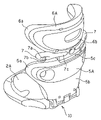
FIG. 1 is a perspective view of a child seat according to an embodiment of the present invention;
FIG. 2 is a perspective view showing a state where a cover is detached from the child seat of FIG. 1 to expose the body of each portion;
FIG. 3 is a view showing a mechanism for connecting a seat body with a backrest body;
FIG. 4 is a view showing a state of suspending a seat portion in a condition that a back portion is disposed at the top thereof;
FIG. 5 is a perspective view of a headrest body when viewed from the rear surface thereof;
FIG. 6 is a view showing a belt guide mechanism mounted in the headrest body;
FIG. 7 is a view showing a state of moving a shoulder belt guide outward in the state shown in FIG. 6;
FIG. 8 is a view showing a state where a lock plate is pulled down to release restriction of the shoulder belt guide;
FIG. 9 is a cross-sectional view of the belt guide mechanism taken along the line IX-IX of FIG. 6;
FIG. 10A is a view showing a state where the shoulder belt guide is pulled outward to properly adjust the guide position of the shoulder belt;
FIG. 10B is a view showing a state where the shoulder belt guide is biased inward to improperly set the guide position of the shoulder belt;
FIG. 11 is a view showing a cross-sectional structure of a ventilation portion provided in a cover;
FIG. 12 is a view showing another example of a mechanism for connecting the seat body with the backrest body;
FIG. 13 is a view showing another example of a belt guide position adjusting mechanism;
FIG. 14 is a view showing a state where the shoulder belt guide is drawn inward from the state shown in FIG. 13; and
FIG. 15 is a cross-sectional view taken along the line XV-XV of FIG. 13.
DESCRIPTION OF THE PREFERRED EMBODIMENT
FIG. 1 shows a child seat according to an embodiment of the present invention. The child seat 1 includes a seat portion 2 and a back portion 3 connected to the rear end of the seat portion 2. The seat portion 2 is a portion on which an infant or a child sit as a sitter and waist belt guides 2 a for correctly positioning a waist belt of a seat belt of a vehicle at the waist of the sitter are provided integrally on both sides of the seat portion 2. A drink holder 4 in which a drink bottle is put is mounted at the front side of the seat portion 2.
The back portion 3 comprises a backrest 5 for supporting the back of the sitter and a headrest 6 disposed at the upper end of the backrest 5. Side supports 5 a and 6 a for supporting the body or the head of the sitter at the sides thereof are disposed integrally with the backrest 5 and the headrest 6 respectively. A seat body 2A, a backrest body 5A, and a headrest body 6A, which are made of resin and shown in FIG. 2 are included inside of the seat portion 2, the backrest 5, and the headrest 6 respectively. The bodies 2A, 5A, and 6A are covered with covers 2B, 5B, and 6B respectively, as shown in FIG. 1. Shoulder belt guides 7 are provided on both lower sides of the headrest 6.
The seat portion 2 and the back portion 3 are rotatably connected to each other through a connecting mechanism 10 interposed between the seat body 2A and the backrest body 5A. The detailed structure of the connecting mechanism 10 is shown in FIG. 3. The connecting mechanism 10 has a spindle 11 provided integrally with the seat body 2A, a hook 12 provided integrally with the lower end of the backrest body 5A, a stopper 13 protruded from the rear end 2 b of the seat body 2A to the spindle 11, and a protrusion 14 provided on the outer circumference of the hook 12. The spindle 11 extends in the left and right directions of the child seat 1 in the rear end of the seat body 2A. The spindle 11 has a flat base portion 11 a which extends in a diameter direction of the spindle 11 in a section perpendicular to the axial direction thereof and a pair of curved portions 11 b and 11 c which is circumferentially in an arc shape curved from both ends of the base portion 11 a. The curved portions 11 b and 11 c are disposed at the front and back sides of the base portion 11 a toward the front and back sides of the seat body 2A respectively.
The hook 12 is formed in a substantially semi-cylindrical shape and has an opening 12 a provided toward the rear surface 5 b of the backrest body 5A. A gap between the outer circumferential surface of the spindle 11 and the stopper 13 is set to be slightly larger than the thickness of the hook 12. As denoted by a solid line in FIG. 3, when the backrest body 5A is in a using position in which the backrest body 5A is raised upwardly relative to the seat body 2A, the opening 12 a of the hook 12 is directed to the back side and the hook 12 is inserted between the spindle 11 and the stopper 13. In this state, the hook 12 cannot be detached from the spindle 11 due to the stopper 13. At this time, the protrusion 14 formed on the outer circumference of the hook 12 is located at the lower side of the hook 12.
As denoted by a dotted line in FIG. 3, when the backrest body 5A falls down at a detachment position which extends substantially straightly from the back side of the seat body 2A, the opening 12 a of the hook 12 is directed to the bottom and the protrusion 14 is brought into contact with the stopper 13. In this state, when the hook 12 is lifted up relative to the spindle 12, the stopper 13 is elastically deformed, and the protrusion 14 passes over the stopper 13. Accordingly, the hook 12 can be pulled up relative to the spindle 11 to separate the backrest body 5A from the seat body 2A. When the hook 12 is pushed down from above relative to the spindle 11 while the backrest body 5A is maintained at the detachment position, the stopper 13 is elastically deformed, the protrusion 14 passes over the stopper 13, and the spindle 11 is inserted into the hook 12. Accordingly, the spindle 11 and the hook 12 engage with each other and the backrest body 5A is rotatably connected to the seat body 2A around the spindle 11. The rigidity of the curved portion 11 b is set such that the curved portion 11 b of the spindle 11 is also elastically deformed together with the stopper 13 when the spindle 11 and the hook 12 are detached from each other.
In the connection mechanism 10 described above, since the seat portion 2 and the back portion 3 elastically engage with each other relative to the detachment and attachment direction therebetween in the state where the backrest body 5A falls down to the detachment position and thus the stopper 13, in some case include the curved portion 11 b of the spindle 11, can be elastically deformed, it is possible to prevent unintended detachment between the seat portion 2 and the back portion 3. For example, when the back portion 3 is manipulated to lift up the child seat 1, as shown in FIG. 4, the seat portion 2 is hung on the back portion 3 and the relationship between the spindle 11 and the hook 12 becomes in the state denoted by a dotted line in FIG. 3. In this state, since the stopper 13 is collided with the protrusion 14 and thus the detachment of the stopper from the hook 12 of the spindle 11 is suppressed, the seat portion 2 is not detached from the back portion 3.
The present invention will be described, returning to FIG. 2. A support fitting groove 5 c upwardly opened is provided in the backrest body 5A, and the headrest body 6A is fitted to the support fitting groove 5 c to be slidable in the upper and lower directions. A headrest positioning mechanism (not shown) for restricting the headrest body 6A to a proper position in the upper and lower directions is provided between the backrest body 5A and the headrest body 6A. Accordingly, the position of the headrest 6 can be adjusted in the upper and lower directions with respect to the backrest 5. By fitting the shoulder belt guides 7 to the headrest body 6A, the positions of the shoulder belt guides 7 can be adjusted in the upper and lower directions along with the headrest 6. A known mechanism can be properly used as the headrest positioning mechanism.
The shoulder belt guides 7 serve to guide the shoulder belt of the seat belt of the vehicle from around the shoulders of the sitter toward the breast. As shown in FIG. 1, the shoulder belt guide 7 comprises a shoulder belt guide hole 7 a through which the shoulder belt passes and a slit 7 b for allowing the shoulder belt to enter and exit from the shoulder belt guide hole 7 a. By attaching the shoulder belt guides 7 to the headrest body 6A through a belt guide positioning mechanism 20 shown in FIGS. 5 to 9, the position of the shoulder belt guides 7 can be adjusted in the left and right directions of the child seat 1.
Next, the belt guide positioning mechanism 20 will be described in detail with reference to FIGS. 5 to 9. FIG. 5 illustrates a view of the shoulder belt guides 7 as seen from the rear surface 6 b of the headrest body 6A, FIGS. 6 to 8 illustrate parts of the belt guide positioning mechanism 20 disposed inside the headrest body 6A, and FIG. 9 illustrates a section of the belt guide positioning mechanism 20 taken along the line IX-IX of FIG. 6. As shown in the figures, the belt guide positioning mechanism 20 comprises a lock plate 21 as a restriction member provided inside the headrest body 6A, a pair of sliders 22 (only one is shown in FIGS. 7 to 9) which is formed to correspond to the shoulder belt guides 7 inside the headrest body 6A and engages with the lock plate 21, and an unlocking knob 23 as a manipulating member for manipulating the lock plate 21.
A lock portion 21 a which is inserted between the right and left sliders 22 and the headrest body 6A and is opposed to the slider 22 at the rear side of the back portion 3 is provided in the lock plate 21. In each lock portion 21 a, a plurality of (two in the figures) lock holes 21 b as a lock receiving portion is provided with a constant pitch in the positioning direction (the left and right directions of the child seat 1) of the shoulder belt guide 7. Lock protrusions 22 a engaging with the lock holes 21 b are provided in the same number and same pitch as the lock holes 21 b in the left and right directions in the sliders 22. A base 7 c of the shoulder belt guide 7 is fit into the guide groove 6 d provided in the headrest body 6A to be movable in the left and right directions. A connection axis 7 d is provided in the shoulder belt guides 7 and the connection axis 7 d is connected to the slider 22 inside the headrest body 6A through an elongated hole 6 e formed in the bottom portion of the guide groove 6 d. Accordingly, inside the headrest body 6A, the sliders 22 are movable in the left and right directions integrally with the shoulder belt guide 7. Spaces in which the lock portions 21A are movable in the front and back directions between a restriction position (the position shown in FIGS. 6 and 9) where the lock holes 21 b engage with the lock protrusions 22 a and a restriction release position where the lock holes 21 b disengage with the lock protrusions 22 a are provided between the sliders 22 and the headrest body 6A.
The unlocking knob 23 has a manipulation portion 23 a which is exposed to the outer surface of the back portion 3 by disposing inside a concave portion 6 c provided at the lower center of the rear surface 6 b of the headrest body 6A, and an axis portion 23 b which extends from the rear center of the manipulation portion 23 a to the inside of the headrest body 6A. The fore end of the axis portion 23 b is connected to the lock plate 21, and thus the lock plate 21 and the unlocking knob 23 are integrally movable in the axis direction of the axis portion 23 b, that is, in the front and back directions of the back portion 3. A coil spring 24 (shown in only FIG. 9) as a biasing means is fit into the outer circumference of the axis portion 23 b. The lock plate 21 is biased to the front direction (in the arrow F direction in FIG. 7) of the headrest body 6A by the coil spring 24, and thus the lock plate 21 is maintained at the restriction position where the lock holes 21 b engage with the lock protrusions 22 a. By allowing the lock holes 21 b to engage with the lock protrusions 22 a, the slider 22 is restricted in the left and right directions to the lock plate 21 and thus the shoulder belt guide 7 cannot move in the left and right directions.
In the belt guide positioning mechanism 20 described above, in order to vary the position of the shoulder belt guide 7 in the left and right directions, the manipulation portion 23 a of the unlocking knob 23 is pulled to the back side of the headrest 6 as indicated by the arrow R in FIG. 8 and the lock plate 21 is moved to the restriction release position where the lock holes 21 b disengage from the lock protrusions 22 a of the slider 22. Accordingly, the restriction of the slider 22 to the lock plate 21 is released and the shoulder belt guide 7 is moved in the left and right directions along the guide groove 6 d, thereby the position thereof can be varied. As shown in FIG. 9, when two lock holes 21 b engage with the lock protrusions 22 a respectively, the shoulder belt guide 7 is restricted to a position retreated to the inside in the left and right directions. When the shoulder belt guide 7 is pulled to the outside by retreating the lock plate 21 to the restriction releasing position from the state shown in FIG. 9 and thus the inner lock protrusions 22 a engage with the outer lock holes 21 b as shown in FIG. 7, the shoulder belt guide 7 can be restricted to a position protruded outwardly from the position shown in FIG. 9. In the figure, by providing two lock holes 21 b and two lock protrusions 22 a, the position of the shoulder belt guide 7 can be adjusted between the two positions. However, the number may be increased so as to adjust the position of the shoulder belt guide 7 in more steps. Alternatively, only one lock protrusion 22 a may be provided and a plurality of lock holes 21 b may be provided. The lock protrusions 22 a may be provided in the lock plate 21 and the lock holes 21 b as the lock receiving portions may be provided in the slider 22. In this case, the number of lock protrusions 22 a may be one or more and the number of lock holes 21 b may be formed to correspond to the number of positions where the shoulder belt guide 7 should be maintained. The lock receiving portion is not limited to the through hole, but may be a concave portion.
As described above, in the child sheet 1 according to the embodiment, since the position in the left and right directions of the shoulder belt guide 7 can be adjusted by the belt guide positioning mechanism 20, the guide position of the shoulder belt can be properly adjusted to correspond to the shoulder width or the neck thickness of the sitter. For example, as shown in FIG. 10B, when the shoulder belt guide 7 is inclined to the inside and a shoulder belt 101 of a seat belt 100 of the vehicle comes in contact with the neck of a sitter 102, the shoulder belt 101 can be guided in a proper route from the shoulder to the breast by moving the shoulder belt guide 7 to the outside as indicated by an arrow D in FIG. 10A. Further, in the child seat 1 according to the embodiment, by attaching the shoulder belt guide 7 to the headrest body 6A through the belt guide positioning mechanism 20, it is possible to adjust the position of the shoulder belt guide 7 in the upper and lower directions. Accordingly, the guide position of the shoulder belt 101 by the shoulder belt guide 7 can be adjusted in the wider range, and thus the shoulder belt can be guided at a proper position for sitters with a variety of physical features. As a result, it is possible to sufficiently enlarge the positioning function of the headrest 6 and the range where the back portion 3 can be used properly.
As shown in FIG. 9, the shoulder belt guide 7 is provided with an expanding portion 7 e formed to be swelled to a front side of the child seat 1 with respect to the base portion 7 c connected to the slider 22, and the guide hole 7 a of the shoulder belt guide 7 is formed in the expanding portion 7 e. The reason for providing the expanding portion 7 e is to forwardly bias the circumference of the guide hole 7 a of the shoulder belt guide 7 with respect to the base portion 7 c attached to the rear surface 6 b of the headrest body 6A, and accordingly, to approximate the guide position of the shoulder belt associated with the shoulder belt guide 7 toward a shoulder of a seated person with respect to front and rear directions. A deep groove 6 f for receiving the expanding portion 7 e is provided in left and right inlet portions of the guide groove 6 d of the headrest body 6A. In addition, the deep grove 6 f is provided with a rib 6 g. The rib 6 g is elongated across the almost entire length of the deep groove 6 f along the left and right directions. The height of the rib 6 g is set so as to reach the base portion 7 c of the shoulder belt guide 7. In other words, the rib 6 g is formed to have a size appropriate to bury the almost entire space of the deep groove 6 f in a top plan view.
On the other hand, the expanding portion 7 e of the shoulder belt guide 7 is provided with a relief groove 7 f for receiving the rib 6 g. As shown in FIG. 9, the rib 6 g is fit into the relief groove 7 f in a state that the shoulder belt guide 7 is positioned in an innermost side. Meanwhile, in a state that the shoulder belt guide 7 is positioned in an outermost side (refer to FIG. 7), the relief groove 7 f is biased toward outside with respect to the rib 6 g, and the step portion between the expanding portion 7 e and the base portion 7 c moves to a position that nearly corresponds with a step portion of the outer side of the rib 6 g as shown as a dashed line 7 e′ of FIG. 9. In other words, even when the shoulder belt guide 7 is fully pulled in an outward direction, the step portion between the base portion 7 c and the expanding portion 7 e is positioned in nearly the same location as that of the rib 6 g of the headrest body 6A. For this reason, even when the shoulder belt guide 7 is outwardly pulled, there is no big gap between the expanding portion 7 e and the headrest body 6A, so that a finger of the user of the child seat 1 is seldom caught in the gap. Furthermore, since the rib 6 g is provided in the deep groove 6 f, it is possible to allow the rib 6 g to prevent penetration of a finger or extraneous materials into the deep grove 6 f.
Then, the characteristic portions of the covers 2B, 5B, and 6B of the child seat 1 will be described. As shown in FIG. 1, the covers 2B, 5B, and 6B of the child seat 1 are provided with ventilation portions 30A, 30B, and 30C respectively. The ventilation portion 30A of the seat portion 2 and the ventilation portion 30B of the backrest 5 are connected with each other, and the ventilation portion 30C of the headrest 6 is isolated from the other ventilation portions 30A and 30B. Theses ventilation portions 30A to 30C are provided to form a recessive concave portion from the surfaces of the covers 2B, 5B, and 6B respectively. Their positions are set in nearly the center of the seat 1 in a right and left direction. As a result, the ventilation portions 30A to 30C constitute a position determining portion for positioning the hip, the back, or the head of a seated person in the center of the seat 1 in a right and left direction. Hereinafter, the ventilation portion may be represented by a reference numeral 30 when a construction common to the ventilation portions 30A to 30C is referred.
FIG. 11 shows a cross-section of the ventilation portion 30. The cross-section of FIG. 11 is common to the ventilation portions 30A to 30C. The ventilation portion 30 is formed by combining an epidermal material 31 disposed at an outermost surface of the covers 2B, 5B, or 6B and a bottom material 32 constituting a bottom surface of the ventilation portion 30 with a gusset material 33 being interposed therebetween. The epidermal material 31 is constructed by bonding a cushion material 31 b such as urethane on the rear surface of the outer cloth 31 a. The epidermal material 31 is notched in association with a planar shape of the ventilation portion 30, and the edge 31 c of the notched portion is folded back toward the rear surface thereof. Meanwhile, the bottom material 32 is constructed by bonding a cushion material 32 b such as urethane on the rear surface of the mesh cloth 32 a having ventilation property, and its shape is set to be slightly larger than that of a planar shape of the ventilation portion 30. The cushion material 32 b is provided with a plurality of ventilation holes (not shown) for obtaining ventilation. The gusset material 33 is formed of a cloth. The gusset material 33 is disposed along the folded edge 31 c of the epidermal material 31 such that a folded line is disposed in an inner circumference in a folded state. The folded edge 31 c of the epidermal material 31 and one folded portion 33 a of the gusset material 33 are sewed with each other along the sew line SL1, and the bottom material 32 and the other folded portion 33 b of the gusset material 33 are sewed with each other along a sew line SL2. This sewing work allows the folded edge 31 a of the epidermal material 31 to be connected with the bottom material 32 through the gusset material 33.
According to the aforementioned ventilation portion structure, since the folded gusset material 33 is interposed between the epidermal material 31 and the bottom material 32, a sufficient height difference between the epidermal material 31 and the bottom material 32 can be obtained. Therefore, it is possible to increase a ventilation effect of the ventilation portion 30 by increasing the depth of the ventilation portion 30. Also, it is possible to increase safety (position determining effect) of a seated person by the ventilation portion 30 by increasing the depth of the ventilation portion 30. In addition, when the folded edge 31 c of the epidermal material 31 and the bottom material 32 are sewed with each other without providing the gusset material 33, the sewed portion is pulled up by tension of the epidermal material 31. As a result, the circumferential portion of the bottom material 32 is raised, and the depth of the ventilation portion 30 is reduced. In other words, in the ventilation portion 30 of this construction, the tension of the epidermal material 31 is buffered by the folded gusset material 33, and the tension of the epidermal material 31 is hardly propagated to the sewed portion between the gusset material 33 and the bottom material 32. For this reason, the swelling of the bottom material 32 is inhibited, and the depth of the ventilation portion 30 is enlarged.
In addition, the width and the position of the sew lines SL1 and SL2 of each of folded portions 33 a and 33 b of the gusset material 33 may be appropriately set based on the tension of the epidermal material 31 or the condition of the sewing work. However, since the swelling by the tension of the epidermal material 31 tends to be significantly generated as the area of the bottom material 32 is smaller, it is preferable that the width of the folded portion 33 b of the gusset material 33 is enlarged as the area of the bottom material 32 is smaller. The folded position of the gusset material 33 is not necessarily identical to that of the epidermal material 31, and the folded position of the gusset material 33 may be pulled toward an inner or outer side from the folded position of the epidermal material 31. The sew lines SL1 and SL2 are not necessarily positioned in the same location, and the sew line SL2 of the gusset material 33 and the bottom material 32 may be positioned in an inner or outer side from the sew line SL1 of the gusset material 33 and the epidermal material 31. However, in order to improve the swelling prevention effect of the bottom material 32, the sew line SL2 is preferably biased toward an outer side. The gusset material 33 is not limited to one sheet, but a plurality of gusset materials 33 may be overlapped in a vertical direction. A cushion material may be provided in the rear surface of the gusset material 33. In addition, each of the seat body 2A, the backrest body 5A, and the headrest body 6A may be provided with a ventilation groove or hole in combination with the ventilation portions 30A, 30B, and 30C respectively.
FIG. 12 shows another example of a connecting mechanism between the seat portion 2 and the back portion 3. In the connecting mechanism 10A shown in FIG. 12, the stopper 13 shown FIG. 3 is omitted, and the hook 12 of the backrest body 5A is provided with first and second hook portions 12A and 12B with the spindle 11 interposed therebetween. In a using position where the backrest body 5A stands up, the first hook portion 12A is located in an inner portion of the spindle 11, and the second hook portion 12B is located at a downstream of the spindle 11. The first hook portion 12A is provided with a stopper 12 b which is arranged to protrude toward the seat body 2A to stop separation of the hook 12 from the spindle 11 when the backrest 5 is located at the using position. The circumferential interval between the first and second hook portions 12A and 12B are designed to be smaller than a diameter of the spindle 11.
In the connecting mechanism 10A shown in FIG. 12, when the backrest body 5A falls down at the detachment position denoted by the dotted line of the figure, the stopper 12 b is released upwardly, and the second hook portion 12B is brought into contact with the curved portion 11 b. Therefore, the backrest body 5A cannot rotate beyond the detachment position to the lower portion of FIG. 12. At the detachment position, the first and second hook portions 12A and 12B are brought into contacted with the circumference of the spindle 11. At the detachment position, the backrest body 5A is moved downwardly in a slanted direction so as to be separated from the seat body 2A, so that the first and second hook portions 12A and 12B are elastically deformed to widen an interval therebetween. As a result, the spindle 11 can be released from the hook 12A. In order to connect the seat portion 2 with the back portion 3, the interval between the first and second hook portions 12A and 12B are aligned with the spindle 11, and the backrest body 5A is pushed toward the seat body 2A. In this state, the interval between the hook portions 12A and 12B is widened, and the spindle 11 is inserted between the interval. In addition, a lower end of the base portion 11 a of the spindle 11 and the second hook portion 12B are provided with taper portions 11 d and 12 d for smoothly elastically deforming the second hook portion 12B.
In the embodiment shown in FIG. 12, even if the backrest body 5A is merely moved to the detachment position with respect to the seat body 2A, the state in which the seat portion 2 and the back portion 3 are engaged with each other is maintained. Therefore, if the engagement portion is not elastically deformed, the spindle 11 and the hook 12 cannot be separated from each other. As a result, similar to the connecting mechanism 10 shown in FIG. 3, an unintentional separation between the seat portion 2 and the back portion 3 can be prevented.
FIGS. 13 to 15 show other embodiments of a belt guide position adjusting mechanism. In these embodiments, a belt guide position adjusting mechanism 20A has a lock plate 40 as a disc-shaped restricting member embedded in the headrest 6A in a state where the lock plate can rotate around an axial line which extends in the front and rear directions of the back portion 3, a manipulating knob 41 as a manipulating member for manipulating a rotation of the lock plate 40, and a pair of links 42 which connect the lock plate 40 with the base portion 7 c of the shoulder belt guide 7. The manipulating knob 41 has a manipulating portion 41 a which is disposed at a rear surface 6 b of the headrest body 6A to be exposed to an outer surface of the back portion 3 and a connection shaft 41 b which penetrates through the headrest body 6A to be inserted therein and connected to a central portion of the lock plate 40. The one end 42 a of the link 42 is rotatably connected to the lock plate 40, and the other end 42 b thereof penetrates from the shoulder belt guide 7 through an elongated hole 6 e of the headrest body 6A to be rotatably connected to the connection shaft 43 embedded therein.
Lock protrusions 40 a are provided on an outer circumference of the lock plate 40 by a separation interval of 90° in the circumferential direction, and the headrest body 6A is provided with recessed portions 44 as a pair of lock receiving portions which are selectively engaged with the lock protrusions 40 a and provided on the circumference of the lock plate 40 by a separation angle of 180°. The connection positions of the link 42 and the lock plate 40 are shifted by 180° in the circumferential direction, and these positions are aligned with a pair of the lock protrusions 40 a in the circumferential direction.
In the belt guide position adjusting mechanism 20A, as shown in FIG. 13, in a state where the lock protrusions 40 a of which position is aligned with the one end 42 a of the link 42 are engaged with the recessed portions 44, the link 42 extends in the left and right directions almost straightly, so that the shoulder belt guide 7 is maintained in a most released position at the outer side in the left and right directions. On the other hand, when the lock plate 40 is rotated from the position shown in FIG. 13 by 90° in the arrow direction A by manipulating the manipulating knob 41 around the connecting shaft 41 b, as shown in FIG. 14, the other lock protrusion 40 a is engaged with the recessed portion 44, so that the one end 42 a of the link 42 is aligned in the up and down direction. Therefore, the connection shaft 43 is inserted along the elongated hole 6 e therein. In this state, the shoulder belt guide 7 is maintained at the position in which the shoulder belt guide is further inserted into the inner portion of FIG. 13 in the left and right directions. In addition, a plurality of the lock protrusions 40 a are provided with a pitch smaller than 90° in the circumferential direction, so that three or more the maintaining positions of the shoulder belt guide 7 may be arranged. Alternatively, a single lock protrusion 40 a may be provided, and a plurality of recessed portions 44 may be provided around the circumference of the lock plate 40. The lock protrusions 40 a may be provided to the headrest body 6A, and the recessed portions 44 may be provided to the lock plate 40. In this case, one or more lock protrusion 40 a may be provided, and the number of the recessed portions 44 may be provided to correspond to the number of the maintaining positions of the shoulder belt guides 7. The lock receiving portion is not limited to the recessed portions 44, but it may be a penetrating hole, a groove, or a slit.
The present invention is not limited to the aforementioned embodiment, but it may be implemented in various suitable manners. For example, in the aforementioned embodiment, the shoulder belt guide 7 and the belt guide position adjusting mechanisms 20 and 20A are attached to the headrest 6, so that the position of the shoulder belt guide 7 can be adjusted in both of the up and down directions and the left and right directions. However, the present invention may include an embodiment where the position of the shoulder belt guide 7 may be adjusted in only the left and right directions. The shoulder belt guide may be attached to the backrest. In a case where the shoulder belt guide is attached to the backrest, a mechanism for adjusting the position of the shoulder belt guide in the up and down directions are provided to the backrest, and the shoulder belt guide may be attached to a driving portion of the mechanism in the up and down directions through the belt guide position adjusting mechanism according to the present invention. In addition, the shoulder belt guide is attached to the back portion in a state where the shoulder belt guide can rotate around the spindle which extends in the front and rear directions of the child seat, so that the position of the shoulder belt guide can be adjusted in the up and down directions as well as in the left and right directions.
In the aforementioned embodiment, the ventilation portion structure of the present invention is provided in the covers of the seat portion and the back portion of the child seat. However, the ventilation portion structure of the present invention is not limited thereto, but it may be implemented in various manners. For example, in a case where it is employed in the child seat, the ventilation portion structure of the present invention may be provided to only the seat portion or to only the back portion. The child seat structure is not limited to a type in which a sitter is restricted by using a seat belt of a vehicle. The ventilation portion structure may be employed in a child seat in which a sitter who is fastened to a seat of the vehicle by using the seat belt for the vehicle is restricted by a seat belt itself. In addition, the ventilation portion structure of the present invention may be employed in a booster type child seat in which only the seat portion is provided. In addition, in other various child products, other than child seat, such as a baby car, a baby rack, a baby carrier, a baby belt, shoes, clothes, and a mat, the ventilation portion structure of the present invention may be provided to a surface where the baby is contact with. The ventilation portion structure of the present invention is not limited to the child products, but is may be employed to covers provided to surfaces of various products, with which a user is in contact. For example, the ventilation portion structure of the present invention may be employed in covers of various products such as chair, sofa, clothes, hat, shoes, and bedclothes or in covers which are integrally formed together with these products.

Claims (4)

1. A child seat having a seat portion and a back portion in which the back portion is provided with a shoulder belt guide for guiding a shoulder belt of a seat belt of a vehicle from around the shoulder to the chest of a sitter comprising: a belt guide position adjusting mechanism for changing the position of the shoulder belt guide in the left and right directions of the back portion,
wherein the shoulder belt guide is movably mounted in the left and right directions relative to a body of the back portion,
wherein the belt guide position adjusting mechanism comprises a slider which can be integrally moved with the shoulder belt guide in the left and right directions, a restricting member which can be moved between a restriction position adjacent to the slider and a restriction releasing position separated from the slider, a biasing member for biasing the restricting member toward the restriction position, and a manipulating member having a manipulating portion exposed on the outer surface of the back portion which causes the restricting member to move from the restriction position to the restriction releasing position by manipulating the manipulating portion, wherein a base portion of the shoulder belt guide is disposed at the rear surface side of the back portion, a guide groove for receiving the base portion of the shoulder belt guide is provided in the body of the back portion, and the slider is embedded in the body of the back portion so as to be located at the front side of the back portion relative to the base portion, and
wherein a lock protrusion is provided on any one of the slider and the restricting member, and a plurality of lock receiving portions, which is engaged with the lock protrusion when the restricting member is disposed at the restriction position and is released from the lock protrusion when the restricting member is disposed at the restriction releasing position, is provided on the other of the slider or the restricting member in line along the left and right directions.
2. The child seat according to claim 1, wherein the slider and the shoulder belt guide are connected to each other through a connection shaft which penetrates through an elongated hole of the left and right directions provided in the body of the back portion, the restricting member is embedded in the body so as to face the slider from the rear side of the back portion, the lock protrusion and the lock receiving portions are provided between the facing surfaces of the slider and the restricting member, and the manipulating member is connected to the restricting member such that the manipulating portion is exposed to the rear surface of the back portion and the manipulating portion and the restricting member can be integrally moved in the front and rear directions of the back portion.
3. The child seat according to claim 2, wherein an expanding portion which expands toward the front side of the back portion further away from the base portion outward in the left and right directions of the base portion is provided on the shoulder belt guide, a deep groove portion which receives the expanding portion when the shoulder belt guide is drawn inward in the left and right directions is provided in the guide groove of the back portion, a rib is provided in the deep groove portion, and a relief groove for receiving the rib is provided in the expanding portion.
4. The child seat according to claim 1, wherein the back portion comprises a backrest which supports the back of the sitter and a headrest which is provided such that the position thereof can be adjusted relative to the backrest in the upper and lower directions and supports the head of the sitter, and the shoulder belt guide and the belt guide position adjusting mechanism are provided in the headrest.
US11/446,173 2005-06-06 2006-06-05 Child seat, ventilation portion structure of article and cover of article comprising the ventilation portion structure, and article for child Expired - Fee Related US7510242B2 (en)

Priority Applications (1)

Application Number Priority Date Filing Date Title
US12/369,209 US7748788B2 (en) 2005-06-06 2009-02-11 Child seat, ventilation portion structure of article and cover of article comprising the ventilation portion structure, and article for child

Applications Claiming Priority (4)

Application Number Priority Date Filing Date Title
JP2005165853A JP2006335326A (en) 2005-06-06 2005-06-06 Vent part structure of article, article cover having the same, article for children, and child seat
JP2005-165853 2005-06-06
JP2005-165845 2005-06-06
JP2005165845A JP4732013B2 (en) 2005-06-06 2005-06-06 child seat

Related Child Applications (1)

Application Number Title Priority Date Filing Date
US12/369,209 Division US7748788B2 (en) 2005-06-06 2009-02-11 Child seat, ventilation portion structure of article and cover of article comprising the ventilation portion structure, and article for child

Publications (2)

Publication Number Publication Date
US20060273637A1 US20060273637A1 (en) 2006-12-07
US7510242B2 true US7510242B2 (en) 2009-03-31

Family

ID=37106294

Family Applications (2)

Application Number Title Priority Date Filing Date
US11/446,173 Expired - Fee Related US7510242B2 (en) 2005-06-06 2006-06-05 Child seat, ventilation portion structure of article and cover of article comprising the ventilation portion structure, and article for child
US12/369,209 Expired - Fee Related US7748788B2 (en) 2005-06-06 2009-02-11 Child seat, ventilation portion structure of article and cover of article comprising the ventilation portion structure, and article for child

Family Applications After (1)

Application Number Title Priority Date Filing Date
US12/369,209 Expired - Fee Related US7748788B2 (en) 2005-06-06 2009-02-11 Child seat, ventilation portion structure of article and cover of article comprising the ventilation portion structure, and article for child

Country Status (5)

Country Link
US (2) US7510242B2 (en)
EP (1) EP1731356A2 (en)
KR (1) KR101342212B1 (en)
HK (1) HK1096636A1 (en)
TW (1) TWI356780B (en)

Cited By (10)

* Cited by examiner, † Cited by third party
Publication number Priority date Publication date Assignee Title
US20090152918A1 (en) * 2005-06-06 2009-06-18 Combi Corporation Child seat, ventilation portion structure of article and cover of article comprising the ventilation portion structure, and article for child
US20110148160A1 (en) * 2009-12-17 2011-06-23 Meeker R & D., Inc. Adjustable shoulder belt path for a booster car seat
US8746794B2 (en) 2011-03-14 2014-06-10 Tiny Love Ltd. Infant bouncer
USD744248S1 (en) * 2013-12-19 2015-12-01 Cybex Gmbh Car seat
US20180043808A1 (en) * 2016-08-12 2018-02-15 Lear Corporation Integrated seat back support member for seat assemblies
US10081273B2 (en) * 2016-01-20 2018-09-25 Dorel Juvenile Group, Inc. Belt-mount system for juvenile vehicle seat
US20190070983A1 (en) * 2017-03-19 2019-03-07 Carfoldio LTD. Apparatus for adapting a seatbelt to a child
US20190217813A1 (en) * 2018-01-12 2019-07-18 Ford Global Technologies, Llc Shoulder belt guide for a vehicle seating assembly
USD876111S1 (en) 2018-09-20 2020-02-25 Cybex Gmbh Child safety seat for motor cars
USD959862S1 (en) 2020-10-27 2022-08-09 Cybex Gmbh Integral child seat

Families Citing this family (17)

* Cited by examiner, † Cited by third party
Publication number Priority date Publication date Assignee Title
AU2007200053A1 (en) * 2006-01-12 2007-07-26 Hts Hans Torgersen & Sonn As Belt guide
ES1063358Y (en) * 2006-06-30 2007-01-16 Jane S A Oo440 CHILD SEAT FOR CARS
US20090091167A1 (en) * 2007-10-04 2009-04-09 Think/Thing Child seating system and method
US20120292965A1 (en) * 2011-05-19 2012-11-22 Baby Trend, Inc. Child car seat
US9376037B1 (en) * 2013-07-09 2016-06-28 Baby Trend, Inc. Car seat
CA2916737C (en) * 2015-01-09 2018-05-01 Wonderland Nurserygoods Company Limited Child seat having an object holder
FR3035833A1 (en) * 2015-05-06 2016-11-11 Dorel France Sa CHILD CAR SEAT HAVING ADJUSTABLE STRAP GUIDING ELEMENTS
US10071654B2 (en) * 2015-10-05 2018-09-11 Mcleanics Technology Corporation Baby alert car seat alarm—smart car seat
CA2945466C (en) * 2015-10-20 2019-05-07 Wonderland Nurserygoods Company Limited Child safety seat
US9610869B1 (en) * 2016-03-08 2017-04-04 Sentry Baby Products, LLC Plush backrest cover with tube-like arms for combination safety/booster seat assembly
US10245981B2 (en) 2016-04-05 2019-04-02 Graco Children's Products Inc. Child's booster seat with detachable belt positioner car seat
US10562419B2 (en) 2016-08-19 2020-02-18 Graco Children's Products, Inc. Child's booster seat
WO2018045188A1 (en) * 2016-09-01 2018-03-08 Dorel Juvenile Group, Inc. Juvenile vehicle seat with cupholder
US10843605B2 (en) * 2018-05-10 2020-11-24 Dorel Juvenile Group, Inc. Headrest-height adjuster for juvenile seat
KR102540926B1 (en) * 2018-10-02 2023-06-08 현대자동차주식회사 Booster seat
CN111483363B (en) * 2019-01-29 2023-03-28 宝钜瑞士股份有限公司 Headrest height adjusting mechanism and child safety seat
US11285853B1 (en) * 2020-12-21 2022-03-29 Ford Global Technologies, Llc Modular seating assembly

Citations (15)

* Cited by examiner, † Cited by third party
Publication number Priority date Publication date Assignee Title
US4569537A (en) * 1983-05-17 1986-02-11 Britax (Wingard) Limited Anchorage means for vehicle safety belts
US4854639A (en) * 1988-01-26 1989-08-08 Britax-Excelsior Limited Child's safety seat
US5263741A (en) * 1992-07-17 1993-11-23 Ford Motor Company Functional belt guide with webbing locator
US5441332A (en) * 1994-04-08 1995-08-15 Trw Vehicle Safety Systems Inc. Seat integrated vehicle safety apparatus
US5460410A (en) * 1993-07-30 1995-10-24 Trw Repa Gmbh Device for adjustably mounting a seat belt fitting to a vehicle bodywork
JPH10100762A (en) 1996-09-25 1998-04-21 Combi Corp Child seat with high permeability
JP2002120614A (en) 2000-10-11 2002-04-23 Combi Corp Child seat
US6592180B2 (en) * 2001-01-23 2003-07-15 Mark Ellis Combs Cup holder for child's car seat and associated method
US6669302B2 (en) * 2001-05-08 2003-12-30 Graco Children's Products Inc. Seat belt position adjusting arrangement for a vehicle seat
US6811186B1 (en) * 2002-03-29 2004-11-02 Lear Corporation Seat belt adjustment mechanism
US6908151B2 (en) * 2003-03-07 2005-06-21 Meeker R&D, Inc. Adjustable and foldable booster car seat
US7055903B2 (en) * 2004-01-09 2006-06-06 Cosco Management, Inc. Adjustor for juvenile vehicle seat
US7232185B2 (en) * 2005-09-15 2007-06-19 Wonderland Nursery Goods Co., Ltd. Adjustable head rest for child car seat
US20070246982A1 (en) * 2004-10-08 2007-10-25 Takata-Petri Ag Child protection system for motor vehicles
US20080023993A1 (en) * 2006-01-12 2008-01-31 Henk Vertegaal Belt Guide

Family Cites Families (17)

* Cited by examiner, † Cited by third party
Publication number Priority date Publication date Assignee Title
US3486789A (en) * 1967-12-28 1969-12-30 Pennsalt Chemicals Corp Adjustable chair
US4712834A (en) * 1986-12-18 1987-12-15 Simula, Inc. Adjustable seat cushion with tension limiting means
US5203607A (en) * 1990-12-11 1993-04-20 Supracor Systems, Inc. Bicycle seat
US5405179A (en) * 1994-03-07 1995-04-11 Jih; Jong-Shyong Elastic seat pad
US5857749A (en) * 1996-05-28 1999-01-12 Jay Medical Ltd. Wheelchair seat assembly with contoured seat pan and cushion and method
US7040710B2 (en) * 2001-01-05 2006-05-09 Johnson Controls Technology Company Ventilated seat
DE10207490C1 (en) * 2002-02-22 2003-06-18 Daimler Chrysler Ag Upholstery for motor vehicle seat has air permeable layers connected to upholstery layers at seams
JP2004098954A (en) 2002-09-12 2004-04-02 Aprica Kassai Inc Child seat for vehicle
WO2004082969A2 (en) * 2003-03-17 2004-09-30 W.E.T. Automotive Systems Ag Air-conditioning device for the passenger area of a vehicle
US7370911B2 (en) * 2003-10-17 2008-05-13 W.E.T. Automotive Systems, Ag Automotive vehicle seat insert
US7040707B2 (en) * 2004-04-13 2006-05-09 Tachi-S Co., Ltd. Seat back of automotive seat
CA2491103C (en) * 2004-05-10 2008-04-29 Faurecia Automotive Seating Canada Limited Seat-belt webbing guide for coupes and convertibles
WO2006086320A1 (en) * 2005-02-07 2006-08-17 L & P Property Management Company Heat, cool, and ventilate system for automotive applications
TWI356780B (en) * 2005-06-06 2012-01-21 Combi Corp Child seat, ventilation portion structure of artic
US7364229B2 (en) * 2005-06-30 2008-04-29 Hwang-Pao Lee Automatic ventilation device for chair
US7478869B2 (en) * 2005-08-19 2009-01-20 W.E.T. Automotive Systems, Ag Automotive vehicle seat insert
US20070102987A1 (en) * 2005-11-04 2007-05-10 Su-Ming Chen Meshed seat cushion for chair

Patent Citations (15)

* Cited by examiner, † Cited by third party
Publication number Priority date Publication date Assignee Title
US4569537A (en) * 1983-05-17 1986-02-11 Britax (Wingard) Limited Anchorage means for vehicle safety belts
US4854639A (en) * 1988-01-26 1989-08-08 Britax-Excelsior Limited Child's safety seat
US5263741A (en) * 1992-07-17 1993-11-23 Ford Motor Company Functional belt guide with webbing locator
US5460410A (en) * 1993-07-30 1995-10-24 Trw Repa Gmbh Device for adjustably mounting a seat belt fitting to a vehicle bodywork
US5441332A (en) * 1994-04-08 1995-08-15 Trw Vehicle Safety Systems Inc. Seat integrated vehicle safety apparatus
JPH10100762A (en) 1996-09-25 1998-04-21 Combi Corp Child seat with high permeability
JP2002120614A (en) 2000-10-11 2002-04-23 Combi Corp Child seat
US6592180B2 (en) * 2001-01-23 2003-07-15 Mark Ellis Combs Cup holder for child's car seat and associated method
US6669302B2 (en) * 2001-05-08 2003-12-30 Graco Children's Products Inc. Seat belt position adjusting arrangement for a vehicle seat
US6811186B1 (en) * 2002-03-29 2004-11-02 Lear Corporation Seat belt adjustment mechanism
US6908151B2 (en) * 2003-03-07 2005-06-21 Meeker R&D, Inc. Adjustable and foldable booster car seat
US7055903B2 (en) * 2004-01-09 2006-06-06 Cosco Management, Inc. Adjustor for juvenile vehicle seat
US20070246982A1 (en) * 2004-10-08 2007-10-25 Takata-Petri Ag Child protection system for motor vehicles
US7232185B2 (en) * 2005-09-15 2007-06-19 Wonderland Nursery Goods Co., Ltd. Adjustable head rest for child car seat
US20080023993A1 (en) * 2006-01-12 2008-01-31 Henk Vertegaal Belt Guide

Cited By (14)

* Cited by examiner, † Cited by third party
Publication number Priority date Publication date Assignee Title
US7748788B2 (en) * 2005-06-06 2010-07-06 Combi Corporation Child seat, ventilation portion structure of article and cover of article comprising the ventilation portion structure, and article for child
US20090152918A1 (en) * 2005-06-06 2009-06-18 Combi Corporation Child seat, ventilation portion structure of article and cover of article comprising the ventilation portion structure, and article for child
US20110148160A1 (en) * 2009-12-17 2011-06-23 Meeker R & D., Inc. Adjustable shoulder belt path for a booster car seat
US8439439B2 (en) * 2009-12-17 2013-05-14 Meeker R &D, Inc. Adjustable shoulder belt path for a booster car seat
US8746794B2 (en) 2011-03-14 2014-06-10 Tiny Love Ltd. Infant bouncer
USD744248S1 (en) * 2013-12-19 2015-12-01 Cybex Gmbh Car seat
US10081273B2 (en) * 2016-01-20 2018-09-25 Dorel Juvenile Group, Inc. Belt-mount system for juvenile vehicle seat
US20180043808A1 (en) * 2016-08-12 2018-02-15 Lear Corporation Integrated seat back support member for seat assemblies
US10661691B2 (en) * 2016-08-12 2020-05-26 Lear Corporation Integrated seat back support member for seat assemblies
US20190070983A1 (en) * 2017-03-19 2019-03-07 Carfoldio LTD. Apparatus for adapting a seatbelt to a child
US20190217813A1 (en) * 2018-01-12 2019-07-18 Ford Global Technologies, Llc Shoulder belt guide for a vehicle seating assembly
US10525930B2 (en) * 2018-01-12 2020-01-07 Ford Global Technologies, Llc Shoulder belt guide for a vehicle seating assembly
USD876111S1 (en) 2018-09-20 2020-02-25 Cybex Gmbh Child safety seat for motor cars
USD959862S1 (en) 2020-10-27 2022-08-09 Cybex Gmbh Integral child seat

Also Published As

Publication number Publication date
TW200711898A (en) 2007-04-01
EP1731356A2 (en) 2006-12-13
US20060273637A1 (en) 2006-12-07
TWI356780B (en) 2012-01-21
US7748788B2 (en) 2010-07-06
KR101342212B1 (en) 2013-12-16
HK1096636A1 (en) 2007-06-08
KR20060127767A (en) 2006-12-13
US20090152918A1 (en) 2009-06-18

Similar Documents

Publication Publication Date Title
US7510242B2 (en) Child seat, ventilation portion structure of article and cover of article comprising the ventilation portion structure, and article for child
KR100338587B1 (en) Juvenile safety car seat, protector, protector for child-care instrument, child-care instrument and bed for neonate
KR102479617B1 (en) Adjustable child carrier with multiple carrying orientations
US7066536B2 (en) Child seat
US6474735B1 (en) Adjustable car seat
US7806472B2 (en) Head support and seat pad assembly for a child seat
CN107264347A (en) Booster seat with removable strip locator automotive seat
US7222917B2 (en) Reversible seat pad
CN102595976A (en) Containing structure for small children fitted with a dynamic backrest
JP4732013B2 (en) child seat
JP4131106B2 (en) child seat
KR20160145588A (en) Cosleeping and sitting support device
JP2006335326A (en) Vent part structure of article, article cover having the same, article for children, and child seat
EP4215413A1 (en) Child safety seat
JP7440249B2 (en) Inner seat for infant seating device
GB2414660A (en) Child seat with adjustable length seat squab
US11259650B2 (en) Systems, methods, and apparatuses for a convertible child booster's seat
JP3879422B2 (en) Vehicle seat device
JP2006141680A (en) Baby carrier
TW202333981A (en) Buckle assembly and baby carrier
JP3147261U (en) Adjustable headrest for child car seat
JP2023024121A (en) child seat
KR200369680Y1 (en) Seats for automobile with baby seats

Legal Events

Date Code Title Description
AS Assignment

Owner name: COMBI CORPORATION, JAPAN

Free format text: ASSIGNMENT OF ASSIGNORS INTEREST;ASSIGNORS:YUMOTO, RYOICHI;ARII, YUSUKE;REEL/FRAME:017980/0870

Effective date: 20060516

STCF Information on status: patent grant

Free format text: PATENTED CASE

FEPP Fee payment procedure

Free format text: PAYOR NUMBER ASSIGNED (ORIGINAL EVENT CODE: ASPN); ENTITY STATUS OF PATENT OWNER: LARGE ENTITY

FPAY Fee payment

Year of fee payment: 4

FPAY Fee payment

Year of fee payment: 8

FEPP Fee payment procedure

Free format text: MAINTENANCE FEE REMINDER MAILED (ORIGINAL EVENT CODE: REM.); ENTITY STATUS OF PATENT OWNER: LARGE ENTITY

LAPS Lapse for failure to pay maintenance fees

Free format text: PATENT EXPIRED FOR FAILURE TO PAY MAINTENANCE FEES (ORIGINAL EVENT CODE: EXP.); ENTITY STATUS OF PATENT OWNER: LARGE ENTITY

STCH Information on status: patent discontinuation

Free format text: PATENT EXPIRED DUE TO NONPAYMENT OF MAINTENANCE FEES UNDER 37 CFR 1.362

FP Lapsed due to failure to pay maintenance fee

Effective date: 20210331