US7488123B2 - Latching mechanism for pluggable transceiver module - Google Patents
Latching mechanism for pluggable transceiver module Download PDFInfo
- Publication number
- US7488123B2 US7488123B2 US11/745,112 US74511207A US7488123B2 US 7488123 B2 US7488123 B2 US 7488123B2 US 74511207 A US74511207 A US 74511207A US 7488123 B2 US7488123 B2 US 7488123B2
- Authority
- US
- United States
- Prior art keywords
- module
- module according
- housing
- lever
- receptacle
- Prior art date
- Legal status (The legal status is an assumption and is not a legal conclusion. Google has not performed a legal analysis and makes no representation as to the accuracy of the status listed.)
- Expired - Fee Related
Links
- 230000007246 mechanism Effects 0.000 title description 6
- 230000003287 optical effect Effects 0.000 claims abstract description 25
- 230000014759 maintenance of location Effects 0.000 claims abstract description 23
- 239000000835 fiber Substances 0.000 claims abstract description 9
- 230000008878 coupling Effects 0.000 claims abstract description 3
- 238000010168 coupling process Methods 0.000 claims abstract description 3
- 238000005859 coupling reaction Methods 0.000 claims abstract description 3
- 230000013011 mating Effects 0.000 claims abstract description 3
- 239000013307 optical fiber Substances 0.000 description 4
- 238000004891 communication Methods 0.000 description 3
- 230000005540 biological transmission Effects 0.000 description 2
- 238000012986 modification Methods 0.000 description 2
- 230000004048 modification Effects 0.000 description 2
- 230000006978 adaptation Effects 0.000 description 1
- 238000010276 construction Methods 0.000 description 1
- 230000000881 depressing effect Effects 0.000 description 1
- 230000007613 environmental effect Effects 0.000 description 1
- 238000000034 method Methods 0.000 description 1
- 230000008569 process Effects 0.000 description 1
- 239000004065 semiconductor Substances 0.000 description 1
Images


Classifications
-
- G—PHYSICS
- G02—OPTICS
- G02B—OPTICAL ELEMENTS, SYSTEMS OR APPARATUS
- G02B6/00—Light guides; Structural details of arrangements comprising light guides and other optical elements, e.g. couplings
- G02B6/24—Coupling light guides
- G02B6/42—Coupling light guides with opto-electronic elements
- G02B6/4292—Coupling light guides with opto-electronic elements the light guide being disconnectable from the opto-electronic element, e.g. mutually self aligning arrangements
-
- G—PHYSICS
- G02—OPTICS
- G02B—OPTICAL ELEMENTS, SYSTEMS OR APPARATUS
- G02B6/00—Light guides; Structural details of arrangements comprising light guides and other optical elements, e.g. couplings
- G02B6/24—Coupling light guides
- G02B6/42—Coupling light guides with opto-electronic elements
- G02B6/4201—Packages, e.g. shape, construction, internal or external details
- G02B6/4274—Electrical aspects
- G02B6/4277—Protection against electromagnetic interference [EMI], e.g. shielding means
-
- G—PHYSICS
- G02—OPTICS
- G02B—OPTICAL ELEMENTS, SYSTEMS OR APPARATUS
- G02B6/00—Light guides; Structural details of arrangements comprising light guides and other optical elements, e.g. couplings
- G02B6/24—Coupling light guides
- G02B6/36—Mechanical coupling means
- G02B6/38—Mechanical coupling means having fibre to fibre mating means
- G02B6/3807—Dismountable connectors, i.e. comprising plugs
- G02B6/389—Dismountable connectors, i.e. comprising plugs characterised by the method of fastening connecting plugs and sockets, e.g. screw- or nut-lock, snap-in, bayonet type
- G02B6/3893—Push-pull type, e.g. snap-in, push-on
Definitions
- the field of the invention relates to optical transceivers, and in particular to the actuator and latching mechanism for a pluggable assembly or module that provides a communications interface between a computer or communications unit having an electrical input/output connector or interface and an optical fiber, such as used in fiber optic communication links.
- optical transceivers include an optical transmit portion that converts an electrical signal into a modulated light beam that is coupled to an optical fiber, and a receive portion that receives an optical signal from an optical fiber and converts it into an electrical signal.
- an optical receive portion includes an optical assembly to focus or direct the light from the optical fiber onto a photodector, which, in turn, is connected to an amplifier/limiter circuit on a circuit board.
- the optical transmit portion contains a photodiode and similar optical provisions and, in turn, is coupled to a driver board.
- the photodetector or photodiode is typically packaged in a hermetically-sealed package in order to protect it from harsh environmental conditions.
- the photodetectors or photodiodes are semiconductor chips that are typically a few hundred microns to a couple of millimeters wide and 100-500 microns thick.
- the package in which a photodetector or photodiode is mounted is typically 3 to 6 mm in diameter and 2 to 5 mm tall, and has several electrical leads coming out of the package which are, in turn, soldered to the circuit board containing the amplifier/limiter or driver.
- Standard form factors provide standardized dimensions and input/output interfaces that allow devices from different manufacturers to be used interchangeably.
- latching mechanisms for large conventional pluggable modules have been used successfully in the past, they tend to be unsuitable for miniaturization which is an ever-constant objective in the industry. It is desirable to miniaturize transceivers in order to increase the port density associated with the network connection, such as, for example, switch boxes, cabling patch panels, wiring closets, and computer I/O.
- the SFP MSA standard i.e., “small form factor pluggable” has been promulgated, and this standard specifies a predetermined enclosure height and width and electrical input/output connections, and a certain latch design. However, the MSA does not specify any actuating mechanism, which is left to each vendor to implement.
- Miniaturizing a module providing a suitable latch actuating mechanism and providing high operating speed, presents a number of design problems, particularly in applications in which data transmission rates are high, e.g., in the range of 1-10 Gbs (Gigabits/second).
- data transmission rates are high, e.g., in the range of 1-10 Gbs (Gigabits/second).
- EMI electromagnetic inference
- SFP small form factor pluggable
- the present invention provides a pluggable module, such as an optical transceiver for coupling an information system unit to a fiber optical cable, and adapted for mating with a receptacle having a retention tab on the bottom surface thereof, including: a housing having a top and a bottom surface; a rotatable lever disposed on an optical connector end of the housing; a pusher element coupled to the rotatable lever and adapted to move parallel to the bottom surface when the lever is actuated; and a spring loaded latch extending from the bottom of the housing for engaging a cavity in the receptacle so as to secure the module in the receptacle, the pusher element engaging the spring loaded latch such that when the movable lever is rotated in a direction away from the housing, the latch is retracted to enable the module to be released from the receptacle.
- a pluggable module such as an optical transceiver for coupling an information system unit to a fiber optical cable, and adapted for mating with a recept
- FIG. 1 is a top, side, perspective view of a pluggable module and a cage for use in an information system in accordance with an illustrated embodiment of the invention
- FIG. 2A is a bottom, side, perspective view of the pluggable module and cage of FIG. 1 ;
- FIG. 2B is an enlarged bottom perspective view of a front end of the pluggable module and cage of FIG. 2A ;
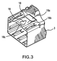
- FIG. 3 is an enlarged bottom perspective view of a front end of the cage showing the retention tab
- FIG. 4 is a top cut-away view of a front portion of the pluggable module of FIG. 1 with a rotatable bail in a closed position;
- FIG. 5 is a perspective view of a pusher element of the pluggable module of FIG. 1 ;
- FIG. 6 is a top cut-away view of a front portion of the pluggable module and cage of FIG. 1 , with the rotatable bail in an open position;
- FIG. 7A is a cross-sectional view of the pluggable module and cage of FIG. 1 with the rotatable bail in a closed position;
- FIG. 7B is a cross-sectional view of the pluggable module and cage of FIG. 1 , with the rotatable bail in an open position;
- FIG. 7C is a cross-sectional view of the pluggable module partially removed from the cage.
- FIG. 1 shows a pluggable optical transceiver module 1 housed within an electromagnetic interference (EMI) cage 3 .
- Fiber optic cables 5 , 7 are removably connected to the pluggable optical transceiver module 1 by means of fiber optic connectors 9 , 11 .
- Each fiber optic connector 9 , 11 is provided with a retaining latch 9 a, 11 a to retain the fiber optic connectors within receiving connector cavities 10 , 12 , in the module 1 . Depressing the retaining latches 9 a, 11 a releases them from associated retainers (not shown), and allows the easy release and removal of the fiber optic connectors 9 , 11 from the receiving cavities 10 , 12 .
- a small form factor pluggable component (SFP) 13 is attached to a lower side of the pluggable optical transceiver module 1 .
- a rotatable bail 14 is pivotally connected to, and extends from, a lower side of the SFP 13 , and this is described in greater detail below.
- FIG. 2A an underside of the module 1 housed within the EMI cage 3 is shown.
- FIG. 2B shows one end of the module 1 and EMI cage 3 in an enlarged scale.
- a spring-loaded retention tab 16 extends from an open end of the EMI cage 3 , the retention tab having an upper region 16 a, a centre region 16 b, and a lip region 16 c formed therein. This can be seen more clearly in FIG. 3 .
- the retention tab 16 is formed such that it extends slightly inwards from the plane of a surface of the EMI cage 3 from which the retention tab extends.
- a triangular shaped hole 18 is formed in the centre region 16 b retention tab 16 .
- a substantially prismatic-shaped protrusion 20 extends from the underside of the SFP 13 .
- the protrusion 20 engages with the lip region 16 c of the retention tab 16 , causing the retention tab to be lifted upwards and slide over the protrusion, until, when the module is fully inserted, the protrusion is aligned with the complementary-shaped triangular hole 18 , allowing the spring loaded retention tab to be urged back to its original position, and with the protrusion extending at least partially through the hole. In this position, the module 1 is effectively locked into the cage 3 , the retention tab 16 and protrusion 20 preventing the module from sliding out of the cage.
- FIG. 4 one end of the SFP 13 is shown.
- a bail 14 is rotatably mounted to the SFP 13 , at pivot points 14 a, 14 b. Offset sections 22 a, 22 b of the bail 14 extend outwards from the general loop shape of the bail 14 , into cavities 23 a, 23 b in the SFP 13 .
- a pusher element 24 is mounted on the SFP 13 , and is movable in a direction parallel to the surface of the SFP.
- a coil spring 26 positioned between a section of the SFP 13 and the pusher element 24 , causes the pusher element to engage the offset regions 22 a, 22 b of the bail 14 .
- the pusher element 24 is shown on its own in greater detail. At one end of the pusher element 24 , a pair of ramps 28 a, 28 b are formed. When positioned in the module 1 , the ramps 28 a, 28 b are adjacent to the lip region 16 c of the retention tab 16 of the cage 3 , as shown in FIG. 2B .
- a user rotates the bail 14 away from the module, from a first position where the bail is in an approximately vertical position, through an angle of approximately 90°, to a second position where the bail is in an approximately horizontal position.
- Rotation about the pivot points 14 a, 14 b causes the offset regions 22 a, 22 b to engage corresponding surfaces 30 a, 30 b of the pusher element 24 .
- the rotation of the offset regions 22 a, 22 b of the bail 14 causes the pusher element 24 to be urged towards the cage 3 , against the resistance of the coil spring 26 .
- FIG. 6 shows in greater detail the situation when the bail 14 has been rotated through an angle of approximately 90°, and is in an open position. In this position, a user is able to use the bail 14 to pull the module 1 out of the cage 3 .
- the process of rotating the bail 14 and removing the module 1 from the cage 3 is shown schematically in the cross-sectional views of FIGS. 7A , 7 B and 7 C.
Abstract
Description
-
- the
protrusion 20 and correspondinghole 18 may be of any other shape, for example, a cuboid protrusion and rectangular hole, or a hexagonal prism protrusion and hexagonal hole; - the
retention tab 16 may be replaced by a plurality of retention tabs; - the
coil spring 26 may be replaced by some other resilient member; - the two
ramps pusher element 24 may be replaced by the single ramp or any number of ramps.
- the
Claims (12)
Priority Applications (1)
| Application Number | Priority Date | Filing Date | Title |
|---|---|---|---|
| US11/745,112 US7488123B2 (en) | 2007-05-07 | 2007-05-07 | Latching mechanism for pluggable transceiver module |
Applications Claiming Priority (1)
| Application Number | Priority Date | Filing Date | Title |
|---|---|---|---|
| US11/745,112 US7488123B2 (en) | 2007-05-07 | 2007-05-07 | Latching mechanism for pluggable transceiver module |
Publications (2)
| Publication Number | Publication Date |
|---|---|
| US20080279510A1 US20080279510A1 (en) | 2008-11-13 |
| US7488123B2 true US7488123B2 (en) | 2009-02-10 |
Family
ID=39969612
Family Applications (1)
| Application Number | Title | Priority Date | Filing Date |
|---|---|---|---|
| US11/745,112 Expired - Fee Related US7488123B2 (en) | 2007-05-07 | 2007-05-07 | Latching mechanism for pluggable transceiver module |
Country Status (1)
| Country | Link |
|---|---|
| US (1) | US7488123B2 (en) |
Cited By (3)
| Publication number | Priority date | Publication date | Assignee | Title |
|---|---|---|---|---|
| US20090220200A1 (en) * | 2008-03-03 | 2009-09-03 | Avago Technologies Fiber Ip (Singapore) Pte. Ltd. | Optical transceiver module and duplex fiber optic connector |
| US20090220227A1 (en) * | 2008-03-03 | 2009-09-03 | Avago Technologies Fiber Ip (Singapore) Pte. Ltd. | Small form factor pluggable (sfp) optical transceiver module and method |
| WO2011116664A1 (en) * | 2010-03-24 | 2011-09-29 | 华为技术有限公司 | Unlocking device for optical module |
Families Citing this family (3)
| Publication number | Priority date | Publication date | Assignee | Title |
|---|---|---|---|---|
| CN201478499U (en) * | 2009-05-18 | 2010-05-19 | 富士康(昆山)电脑接插件有限公司 | Plug connector |
| US9229177B1 (en) * | 2014-07-16 | 2016-01-05 | Sanwa Denki Kogyo Co., Ltd. | Backlash prevention mechanism of adapter for optical connector |
| TWI740692B (en) * | 2020-09-08 | 2021-09-21 | 劉美妙 | Optical connector and optical connector module and operation method using the same |
Citations (2)
| Publication number | Priority date | Publication date | Assignee | Title |
|---|---|---|---|---|
| US6786653B1 (en) * | 2003-04-16 | 2004-09-07 | Hon Hai Precision Ind. Co., Ltd. | Pluggable transceiver module having release mechanism |
| US20070140626A1 (en) * | 2005-12-19 | 2007-06-21 | Emcore Corporation | Latching mechanism for pluggable transceiver |
-
2007
- 2007-05-07 US US11/745,112 patent/US7488123B2/en not_active Expired - Fee Related
Patent Citations (2)
| Publication number | Priority date | Publication date | Assignee | Title |
|---|---|---|---|---|
| US6786653B1 (en) * | 2003-04-16 | 2004-09-07 | Hon Hai Precision Ind. Co., Ltd. | Pluggable transceiver module having release mechanism |
| US20070140626A1 (en) * | 2005-12-19 | 2007-06-21 | Emcore Corporation | Latching mechanism for pluggable transceiver |
Cited By (7)
| Publication number | Priority date | Publication date | Assignee | Title |
|---|---|---|---|---|
| US20090220200A1 (en) * | 2008-03-03 | 2009-09-03 | Avago Technologies Fiber Ip (Singapore) Pte. Ltd. | Optical transceiver module and duplex fiber optic connector |
| US20090220227A1 (en) * | 2008-03-03 | 2009-09-03 | Avago Technologies Fiber Ip (Singapore) Pte. Ltd. | Small form factor pluggable (sfp) optical transceiver module and method |
| US7798727B2 (en) | 2008-03-03 | 2010-09-21 | Avago Technologies Fiber Ip (Singapore) Pte. Ltd. | Optical transceiver module and duplex fiber optic connector |
| US7824113B2 (en) * | 2008-03-03 | 2010-11-02 | Avago Technologies Fiber Ip (Singapore) Pte. Ltd. | Small form factor pluggable (SFP) optical transceiver module and method |
| US20110019998A1 (en) * | 2008-03-03 | 2011-01-27 | Avago Technologies Fiber Ip (Singapore) Pte. Ltd. | Small form factor pluggable (sfp) optical transceiver module and method |
| US8100588B2 (en) * | 2008-03-03 | 2012-01-24 | Avago Technologies Fiber Ip (Singapore) Pte. Ltd. | Small form factor pluggable (SFP) optical transceiver module and method |
| WO2011116664A1 (en) * | 2010-03-24 | 2011-09-29 | 华为技术有限公司 | Unlocking device for optical module |
Also Published As
| Publication number | Publication date |
|---|---|
| US20080279510A1 (en) | 2008-11-13 |
Similar Documents
| Publication | Publication Date | Title |
|---|---|---|
| US7380995B2 (en) | Latching mechanism for pluggable transceiver | |
| JP4093862B2 (en) | Optical fiber module latch release mechanism | |
| US7118281B2 (en) | Retention and release mechanisms for fiber optic modules | |
| US6890206B2 (en) | Optical transceiver latch | |
| US7507111B2 (en) | Electronic modules having integrated lever-activated latching mechanisms | |
| US6796715B2 (en) | Fiber optic modules with pull-action de-latching mechanisms | |
| US7488123B2 (en) | Latching mechanism for pluggable transceiver module | |
| US6863448B2 (en) | Method and apparatus for push button release fiber optic modules | |
| US6991481B1 (en) | Method and apparatus for a latchable and pluggable electronic and optical module | |
| US20110268390A1 (en) | Active optical cable that is suited for consumer applications and a method | |
| US7056156B1 (en) | Vertically offset EMI projections | |
| US20060121769A1 (en) | Transceiver delatching mechanism | |
| US6840680B1 (en) | Retention and release mechanisms for fiber optic modules | |
| US10156689B2 (en) | Latch for communication module | |
| WO2007037946A2 (en) | Cageless, pluggable optoelectronic device | |
| US20050227518A1 (en) | Pluggable transceiver with cover resilient member | |
| WO2007137287A2 (en) | Cageless, pluggable optoelectronic device which enables belly-to-belly layouts | |
| KR20060024108A (en) | Pluggable optical transceiver module assembly | |
| CN110768727B (en) | Optical transceiver |
Legal Events
| Date | Code | Title | Description |
|---|---|---|---|
| AS | Assignment |
Owner name: EMCORE CORPORATION, NEW JERSEY Free format text: ASSIGNMENT OF ASSIGNORS INTEREST;ASSIGNOR:CHAN, SENG-KUM;REEL/FRAME:019257/0004 Effective date: 20070430 |
|
| AS | Assignment |
Owner name: BANK OF AMERICA, N.A., ILLINOIS Free format text: SECURITY AGREEMENT;ASSIGNOR:EMCORE CORPORATION;REEL/FRAME:021824/0019 Effective date: 20080926 Owner name: BANK OF AMERICA, N.A.,ILLINOIS Free format text: SECURITY AGREEMENT;ASSIGNOR:EMCORE CORPORATION;REEL/FRAME:021824/0019 Effective date: 20080926 |
|
| AS | Assignment |
Owner name: WELLS FARGO BANK, NATIONAL ASSOCIATION, ARIZONA Free format text: SECURITY AGREEMENT;ASSIGNORS:EMCORE CORPORATION;EMCORE SOLAR POWER, INC.;REEL/FRAME:026304/0142 Effective date: 20101111 |
|
| AS | Assignment |
Owner name: EMCORE SOLAR POWER, INC., NEW MEXICO Free format text: RELEASE BY SECURED PARTY;ASSIGNOR:BANK OF AMERICA, N.A.;REEL/FRAME:027050/0880 Effective date: 20110831 Owner name: EMCORE CORPORATION, NEW MEXICO Free format text: RELEASE BY SECURED PARTY;ASSIGNOR:BANK OF AMERICA, N.A.;REEL/FRAME:027050/0880 Effective date: 20110831 |
|
| AS | Assignment |
Owner name: EMCORE SOLAR POWER, INC., NEW MEXICO Free format text: PARTIAL RELEASE OF SECURITY INTEREST;ASSIGNOR:WELLS FARGO BANK, NATIONAL ASSOCIATION;REEL/FRAME:028192/0189 Effective date: 20120507 Owner name: EMCORE CORPORATION, NEW MEXICO Free format text: PARTIAL RELEASE OF SECURITY INTEREST;ASSIGNOR:WELLS FARGO BANK, NATIONAL ASSOCIATION;REEL/FRAME:028192/0189 Effective date: 20120507 |
|
| REMI | Maintenance fee reminder mailed | ||
| LAPS | Lapse for failure to pay maintenance fees | ||
| AS | Assignment |
Owner name: SUMITOMO ELECTRIC DEVICE INNOVATIONS, U.S.A., INC. Free format text: ASSIGNMENT OF ASSIGNORS INTEREST;ASSIGNOR:EMCORE CORPORATION;REEL/FRAME:030006/0126 Effective date: 20130225 |
|
| STCH | Information on status: patent discontinuation |
Free format text: PATENT EXPIRED DUE TO NONPAYMENT OF MAINTENANCE FEES UNDER 37 CFR 1.362 |
|
| FP | Lapsed due to failure to pay maintenance fee |
Effective date: 20130210 |