US7482909B2 - Night vision device - Google Patents
Night vision device Download PDFInfo
- Publication number
- US7482909B2 US7482909B2 US11/150,726 US15072605A US7482909B2 US 7482909 B2 US7482909 B2 US 7482909B2 US 15072605 A US15072605 A US 15072605A US 7482909 B2 US7482909 B2 US 7482909B2
- Authority
- US
- United States
- Prior art keywords
- night vision
- assister
- motor vehicle
- marking
- control unit
- Prior art date
- Legal status (The legal status is an assumption and is not a legal conclusion. Google has not performed a legal analysis and makes no representation as to the accuracy of the status listed.)
- Expired - Fee Related, expires
Links
- 230000004297 night vision Effects 0.000 title claims abstract description 106
- 230000000007 visual effect Effects 0.000 description 4
- 238000011156 evaluation Methods 0.000 description 3
- 230000003068 static effect Effects 0.000 description 3
- 238000004364 calculation method Methods 0.000 description 2
- 238000001514 detection method Methods 0.000 description 2
- 238000010586 diagram Methods 0.000 description 2
- 238000005286 illumination Methods 0.000 description 2
- 238000000034 method Methods 0.000 description 2
- 230000005855 radiation Effects 0.000 description 2
- 238000003703 image analysis method Methods 0.000 description 1
- 238000003780 insertion Methods 0.000 description 1
- 230000037431 insertion Effects 0.000 description 1
- 230000005043 peripheral vision Effects 0.000 description 1
Images


Classifications
-
- G—PHYSICS
- G01—MEASURING; TESTING
- G01S—RADIO DIRECTION-FINDING; RADIO NAVIGATION; DETERMINING DISTANCE OR VELOCITY BY USE OF RADIO WAVES; LOCATING OR PRESENCE-DETECTING BY USE OF THE REFLECTION OR RERADIATION OF RADIO WAVES; ANALOGOUS ARRANGEMENTS USING OTHER WAVES
- G01S5/00—Position-fixing by co-ordinating two or more direction or position line determinations; Position-fixing by co-ordinating two or more distance determinations
- G01S5/16—Position-fixing by co-ordinating two or more direction or position line determinations; Position-fixing by co-ordinating two or more distance determinations using electromagnetic waves other than radio waves
-
- B—PERFORMING OPERATIONS; TRANSPORTING
- B60—VEHICLES IN GENERAL
- B60R—VEHICLES, VEHICLE FITTINGS, OR VEHICLE PARTS, NOT OTHERWISE PROVIDED FOR
- B60R1/00—Optical viewing arrangements; Real-time viewing arrangements for drivers or passengers using optical image capturing systems, e.g. cameras or video systems specially adapted for use in or on vehicles
- B60R1/20—Real-time viewing arrangements for drivers or passengers using optical image capturing systems, e.g. cameras or video systems specially adapted for use in or on vehicles
- B60R1/22—Real-time viewing arrangements for drivers or passengers using optical image capturing systems, e.g. cameras or video systems specially adapted for use in or on vehicles for viewing an area outside the vehicle, e.g. the exterior of the vehicle
- B60R1/23—Real-time viewing arrangements for drivers or passengers using optical image capturing systems, e.g. cameras or video systems specially adapted for use in or on vehicles for viewing an area outside the vehicle, e.g. the exterior of the vehicle with a predetermined field of view
- B60R1/24—Real-time viewing arrangements for drivers or passengers using optical image capturing systems, e.g. cameras or video systems specially adapted for use in or on vehicles for viewing an area outside the vehicle, e.g. the exterior of the vehicle with a predetermined field of view in front of the vehicle
-
- B—PERFORMING OPERATIONS; TRANSPORTING
- B60—VEHICLES IN GENERAL
- B60R—VEHICLES, VEHICLE FITTINGS, OR VEHICLE PARTS, NOT OTHERWISE PROVIDED FOR
- B60R1/00—Optical viewing arrangements; Real-time viewing arrangements for drivers or passengers using optical image capturing systems, e.g. cameras or video systems specially adapted for use in or on vehicles
- B60R1/20—Real-time viewing arrangements for drivers or passengers using optical image capturing systems, e.g. cameras or video systems specially adapted for use in or on vehicles
- B60R1/30—Real-time viewing arrangements for drivers or passengers using optical image capturing systems, e.g. cameras or video systems specially adapted for use in or on vehicles providing vision in the non-visible spectrum, e.g. night or infrared vision
-
- G—PHYSICS
- G08—SIGNALLING
- G08G—TRAFFIC CONTROL SYSTEMS
- G08G1/00—Traffic control systems for road vehicles
- G08G1/16—Anti-collision systems
- G08G1/167—Driving aids for lane monitoring, lane changing, e.g. blind spot detection
-
- B—PERFORMING OPERATIONS; TRANSPORTING
- B60—VEHICLES IN GENERAL
- B60R—VEHICLES, VEHICLE FITTINGS, OR VEHICLE PARTS, NOT OTHERWISE PROVIDED FOR
- B60R2300/00—Details of viewing arrangements using cameras and displays, specially adapted for use in a vehicle
- B60R2300/10—Details of viewing arrangements using cameras and displays, specially adapted for use in a vehicle characterised by the type of camera system used
- B60R2300/106—Details of viewing arrangements using cameras and displays, specially adapted for use in a vehicle characterised by the type of camera system used using night vision cameras
-
- B—PERFORMING OPERATIONS; TRANSPORTING
- B60—VEHICLES IN GENERAL
- B60R—VEHICLES, VEHICLE FITTINGS, OR VEHICLE PARTS, NOT OTHERWISE PROVIDED FOR
- B60R2300/00—Details of viewing arrangements using cameras and displays, specially adapted for use in a vehicle
- B60R2300/30—Details of viewing arrangements using cameras and displays, specially adapted for use in a vehicle characterised by the type of image processing
- B60R2300/304—Details of viewing arrangements using cameras and displays, specially adapted for use in a vehicle characterised by the type of image processing using merged images, e.g. merging camera image with stored images
- B60R2300/305—Details of viewing arrangements using cameras and displays, specially adapted for use in a vehicle characterised by the type of image processing using merged images, e.g. merging camera image with stored images merging camera image with lines or icons
-
- B—PERFORMING OPERATIONS; TRANSPORTING
- B60—VEHICLES IN GENERAL
- B60R—VEHICLES, VEHICLE FITTINGS, OR VEHICLE PARTS, NOT OTHERWISE PROVIDED FOR
- B60R2300/00—Details of viewing arrangements using cameras and displays, specially adapted for use in a vehicle
- B60R2300/80—Details of viewing arrangements using cameras and displays, specially adapted for use in a vehicle characterised by the intended use of the viewing arrangement
- B60R2300/804—Details of viewing arrangements using cameras and displays, specially adapted for use in a vehicle characterised by the intended use of the viewing arrangement for lane monitoring
-
- B—PERFORMING OPERATIONS; TRANSPORTING
- B60—VEHICLES IN GENERAL
- B60R—VEHICLES, VEHICLE FITTINGS, OR VEHICLE PARTS, NOT OTHERWISE PROVIDED FOR
- B60R2300/00—Details of viewing arrangements using cameras and displays, specially adapted for use in a vehicle
- B60R2300/80—Details of viewing arrangements using cameras and displays, specially adapted for use in a vehicle characterised by the intended use of the viewing arrangement
- B60R2300/8053—Details of viewing arrangements using cameras and displays, specially adapted for use in a vehicle characterised by the intended use of the viewing arrangement for bad weather conditions or night vision
Definitions
- the present invention relates to a night vision device for motor vehicles having at least one night vision camera, one control unit and one display unit for displaying a night vision image.
- Night vision devices for motor vehicles are described, for example, in PCT Patent Publication No. WO 02/36389. They have night vision cameras, which, for example, on the basis of near infrared with active illumination (NIR) or on the basis of head radiation (FIR) take a picture of the surroundings of the vehicle with a visual range that normally exceeds the visual range of the human eye.
- the image of the surroundings of the vehicle is displayed to the driver via a display unit.
- the display unit may be a conventional display in a dashboard or a head-up display, which projects the image onto the windshield with the aid of a projector. Head-up projectors are described, for example, in German Patent Application No. DE 101 31 720.
- Driving according to a display with the aid of the pure night vision image is relatively difficult since it is hard to estimate relative positions in the traffic lane by the displayed night vision image. Even on very well-constructed roads such as highways and superhighways, which have very good lane markings and large radii of curvature, driving according to a display of the night vision image is possible only with difficulty. In addition, the distance to other objects, particularly to preceding vehicles, is very hard to estimate. Even with great practice of driving according to a displayed night vision image, maintaining a suitable safety distance is possible only with difficulty since the night vision image was often shot using a different aperture angle than the picture perceived by the human eye through the windshield.
- An objective of the present invention is to provide an improved night vision device, which facilitates the guidance of a motor vehicle while observing the displayed night vision image.
- control unit is designed to ascertain and display assister markings for longitudinal and/or lateral guidance when driving the motor vehicle.
- the assister markings inserted or permanently attached to the display unit provide in a simple manner a substantial assistance in the longitudinal and/or lateral guidance of the motor vehicle.
- the assister markings are preferably assister lines.
- At least one assister marking for representing the lane center or lane limits of a traffic lane and at least one assister marking for representing the vehicle center or the vehicle width are ascertained and displayed on the night vision image.
- the at least one assister marking for representing the vehicle center or vehicle width may either be currently calculated or definitely specified, i.e. ascertained only once, since the camera coordinates have fixed relations with respect to the vehicle coordinates.
- the assister marking for representing the lane center or the lane limits of a traffic lane may be determined in a simple manner from the night vision image using known image analysis methods. The driver then only needs to guide the vehicle according to the assister markings such that the assister markings of the lane center and vehicle center or the assister markings for the vehicle position and the lane markings are made to coincide symmetrically.
- the at least one assister marking is preferably ascertained as a function of the angle and of the lateral offset between the sensor axis of the night vision image sensor and the longitudinal axis of the motor vehicle. This angle and this offset determine the perspective of the night vision image and the position relative to the vehicle center or the vehicle limits.
- control unit is designed for calculating the current position of the vehicle in a traffic lane from the night vision image and for comparing to a setpoint position for ascertaining and displaying a correction vector.
- the correction vector already implies a comparison, otherwise to be conducted by the driver, between the actual and the setpoint position and is very easy for the driver to apprehend.
- distance assister lines having definitively specified distances are statically displayed from the motor vehicle forward in the direction of travel. This may occur for example by permanently attached markings on the display unit or by a static insertion of the distance assister lines superimposed with respect to the night vision image.
- control unit is designed to ascertain and display a setpoint distance with respect to a preceding vehicle as a function of the vehicle's own velocity.
- the control unit may additionally be connected to surround sensors for ascertaining parameters of the weather situation and/or of the road condition and be designed to ascertain the setpoint distance as a function of the ascertained parameters.
- control unit is connected to a navigation device and is designed to ascertain the assister markings as a function of parameters provided by the navigation device.
- parameters may be, for example, the course of the road such that the setpoint distance is increased in the case of a curvaceous route.
- the control unit may preferably be connected to an anti-collision device, at least one collision object provided by the anti-collision device in three-dimensional relative coordinates being projected into the two-dimensional night vision image.
- the combination having an anti-collision device has the advantage that the driver is able to understand how the longitudinal regulation of the anti-collision device corrects the actual position in the direction of the setpoint position by braking or accelerating the motor vehicle.
- a combination of the night vision device and a lane tracking device may be provided as well, which is preferably based on the same image information of the image sensor and the same lane detection algorithm as it is used by the night vision device. The driver is thereby visually shown the quality of the lane detection as well as the lateral regulation process.
- FIG. 1 shows a block diagram of a night vision device for motor vehicles.
- FIG. 2 shows a sketch of a night vision image having inserted assister markings.
- FIG. 3 shows a sketch of a night vision image having inserted assister lines for lateral guidance.
- FIG. 4 shows a sketch of a night vision image having inserted horizontal assister lines for representing distance.
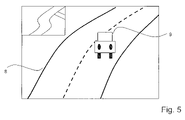
- FIG. 5 shows a sketch of a night vision image having an inserted map detail, which is provided by a navigation device for representing the further course of the road.
- FIG. 1 reveals a block diagram of a night vision device 1 , which essentially has a night vision camera 2 , a display unit 3 for a night vision image as well as a control unit 4 .
- the night vision camera may function on the basis of near infrared with active illumination (NIR) or on the basis of heat radiation (FIR).
- Control unit 4 is preferably programmable and has a microprocessor and/or an FPGA (field programmable gate array) or ASIC (application specific integrated circuit).
- Display unit 3 may be a conventional display or a head-up projector or the like.
- Guiding a motor vehicle according to the night vision image represented in display unit 3 is problematic since the relative position of the motor vehicle in the traffic lane as well as the distance with respect to other objects can be estimated only with difficulty. This is due to the fact that night vision device 1 was often shot using a different aperture angle and/or different shooting positions than the actual picture of the surroundings registered by the driver through the windshield and that peripheral vision is insufficient due to small horizontal aperture angles. In addition, the night vision images are possibly even enlarged or reduced.
- control unit 4 for example is designed by suitable programming to ascertain and display assister markings, particularly assister lines, for longitudinal and/or lateral guidance. This allows the driver to guide the motor vehicle in dependence on the assister lines, for example by correcting the vehicle position towards the right and left by the steering wheel angle and by braking or accelerating for adjusting the distance.
- control unit 4 is connected to a navigation device 5 for relaying additional parameters, such as for example the further course of the road, to night vision device 1 for evaluation and display.
- control unit 4 may be optionally connected to an anti-collision device 6 , particularly in order to transmit collision objects provided by anti-collision device 6 to night vision device 1 for evaluation and display.
- control unit 4 may be furthermore connected to a lane tracking device 7 in order to relay lateral regulation parameters and lane information of lane tracking device 7 to night vision device 1 for evaluation and display.
- Control unit 4 may furthermore be designed for evaluating additional parameters provided by surround sensors either via the mentioned navigation devices 5 , anti-collision devices 6 or lane tracking devices 7 or separately. These parameters are then displayed and, if required, used for ascertaining the assister markings for the longitudinal and/or lateral guidance of the motor vehicle.
- FIG. 2 shows a sketch of an exemplary night vision image having several assister markings.
- the night vision image shows a curved course of the road 8 , at least one preceding vehicle 9 .
- control unit 4 For lateral guidance, control unit 4 displays assister markings 11 for representing the lane center or the lane limits of the traffic lane (setpoint lateral position) as well as a bar-shaped assister marking 12 for displaying the ACTUAL lateral position of the vehicle or the vehicle center or vehicle width.
- An arrow-shaped correction vector 13 above this assister marking 11 , 12 indicates that a correction of the vehicle position to the left is required.
- a horizontal assister line 14 is inserted, which reveals the minimum safety distance with respect to preceding vehicle 9 .
- This assister line 14 is determined by control unit 4 as a function of the motor vehicle's own velocity and possibly by additional parameters such as the weather situation, visibility etc.
- a point marking 15 which was calculated by the anti-collision device by projection from the 3D object position.
- an arrow marking 16 for example a bent arrow, is provided for representing the further course of the road.
- This arrow marking 16 can be determined from the night vision image.
- the arrow marking is calculated on the basis of information regarding the course of the road provided by a navigation device 5 since in this manner it is possible to provide lane courses even if the visibility of the night vision device is limited (e.g. in front of crests), or which exceed the visual range of the night vision device.
- FIG. 3 shows the exemplary night vision image from FIG. 2 having simplified assister markings 17 for lateral guidance.
- Assister markings 17 are two markers permanently inserted in display unit 3 or attached to display unit 3 , which assist the driver in lateral guidance. In guiding the motor vehicle, these fixed static assister markings 17 must be made to coincide or to be symmetrical with respect to the boundary markings of the traffic lane visible in the night vision image.
- the distance between assister markings 17 is chosen so as to correspond to the average lane width. This can be adjusted on the basis of the navigation device (e.g. to typical road types: superhighway, highway, city).
- the position of assister markings 17 is chosen in such a way that the vehicle is located precisely at the center of the lane if assister markings 17 match the markings of a normal traffic lane 8 or lie symmetrically between these or symmetrically around these.
- the position of assister markings 17 is determined from the relative positions and relative axis of night vision camera 2 , the vehicle and the lane width.
- FIG. 3 reveals that the vehicle is clearly situated too far to the right.
- the driver is now able to correct the lateral direction of the vehicle accordingly by steering. This is true even if the lane width of traffic lane 8 varies. In that case, a correction of the vehicle position occurs in such a way that assister markings 17 on the left and on the right are equidistant from the lane markings or lie symmetrically between these or symmetrically around these.
- the position of assister markings 17 are determined from the relative position and the relative axis of camera and vehicle.
- the calculation of assister marking 17 is based on the fixed correlation between the shooting axis of night vision camera 2 and the longitudinal axis of the motor vehicle such that the positions of assister markings 17 have to be ascertained only once in the calibration of night vision camera 2 with respect to the motor vehicle.
- FIG. 4 shows the exemplary night vision image from FIG. 2 having assister markings 18 for longitudinal guidance.
- Assister markings 18 are static distance assister lines for the longitudinal guidance of the vehicle, which are inserted into the night vision image along with their distance to the driver's own motor vehicle or are permanently attached to display unit 3 . With the aid of these distance assister lines 18 , the driver himself is then able to regulate the distance to preceding vehicles for example according to the rule “distance is equal to half of the speedometer reading”.
- the calculation of the position of distance assister lines 18 on display unit 3 occurs on the basis of a simple projection on the assumption of a flat roadway without vertical curvature.
- the curvature of the roadway may be taken into consideration by information from navigation device 5 or other three-dimensional information such as, for example, a stereo camera.
- FIG. 5 shows a sketch of an exemplary night vision image having a map detail inserted on the upper left.
- the data of the map detail are provided by a navigation device which is connectable to night vision device 1 .
- the driver is shown the further course of the road particularly beyond the visual range of navigation device 1 .
Abstract
In a night vision device for motor vehicles having at least one night vision camera, a control unit and a display unit for displaying a night vision image, the control unit is designed to ascertain and display assister markings for longitudinal and/or lateral guidance while driving the motor vehicle.
Description
The present invention relates to a night vision device for motor vehicles having at least one night vision camera, one control unit and one display unit for displaying a night vision image.
Night vision devices for motor vehicles are described, for example, in PCT Patent Publication No. WO 02/36389. They have night vision cameras, which, for example, on the basis of near infrared with active illumination (NIR) or on the basis of head radiation (FIR) take a picture of the surroundings of the vehicle with a visual range that normally exceeds the visual range of the human eye. The image of the surroundings of the vehicle is displayed to the driver via a display unit. The display unit may be a conventional display in a dashboard or a head-up display, which projects the image onto the windshield with the aid of a projector. Head-up projectors are described, for example, in German Patent Application No. DE 101 31 720.
Driving according to a display with the aid of the pure night vision image is relatively difficult since it is hard to estimate relative positions in the traffic lane by the displayed night vision image. Even on very well-constructed roads such as highways and superhighways, which have very good lane markings and large radii of curvature, driving according to a display of the night vision image is possible only with difficulty. In addition, the distance to other objects, particularly to preceding vehicles, is very hard to estimate. Even with great practice of driving according to a displayed night vision image, maintaining a suitable safety distance is possible only with difficulty since the night vision image was often shot using a different aperture angle than the picture perceived by the human eye through the windshield.
From German Patent Application No. DE 199 40 723, a method for displaying a perspective image is known, in which image elements are changed in at least one variable as a function of the travel path ahead, of at least one operating parameter of the vehicle and/or of at least one parameter of an object identified in the region of the travel path.
An objective of the present invention is to provide an improved night vision device, which facilitates the guidance of a motor vehicle while observing the displayed night vision image.
According to the present invention, the objective is achieved in that the control unit is designed to ascertain and display assister markings for longitudinal and/or lateral guidance when driving the motor vehicle.
The assister markings inserted or permanently attached to the display unit provide in a simple manner a substantial assistance in the longitudinal and/or lateral guidance of the motor vehicle. The assister markings are preferably assister lines.
For lateral guidance, preferably at least one assister marking for representing the lane center or lane limits of a traffic lane and at least one assister marking for representing the vehicle center or the vehicle width are ascertained and displayed on the night vision image. The at least one assister marking for representing the vehicle center or vehicle width may either be currently calculated or definitely specified, i.e. ascertained only once, since the camera coordinates have fixed relations with respect to the vehicle coordinates.
The assister marking for representing the lane center or the lane limits of a traffic lane may be determined in a simple manner from the night vision image using known image analysis methods. The driver then only needs to guide the vehicle according to the assister markings such that the assister markings of the lane center and vehicle center or the assister markings for the vehicle position and the lane markings are made to coincide symmetrically.
The at least one assister marking is preferably ascertained as a function of the angle and of the lateral offset between the sensor axis of the night vision image sensor and the longitudinal axis of the motor vehicle. This angle and this offset determine the perspective of the night vision image and the position relative to the vehicle center or the vehicle limits.
It is especially advantageous if the control unit is designed for calculating the current position of the vehicle in a traffic lane from the night vision image and for comparing to a setpoint position for ascertaining and displaying a correction vector. The correction vector already implies a comparison, otherwise to be conducted by the driver, between the actual and the setpoint position and is very easy for the driver to apprehend.
For longitudinal guidance it is advantageous if, in the vertical direction of the display, distance assister lines having definitively specified distances are statically displayed from the motor vehicle forward in the direction of travel. This may occur for example by permanently attached markings on the display unit or by a static insertion of the distance assister lines superimposed with respect to the night vision image.
It is especially advantageous, however, if the control unit is designed to ascertain and display a setpoint distance with respect to a preceding vehicle as a function of the vehicle's own velocity.
The control unit may additionally be connected to surround sensors for ascertaining parameters of the weather situation and/or of the road condition and be designed to ascertain the setpoint distance as a function of the ascertained parameters.
In this manner it is possible to ascertain and display a current setpoint distance while taking the relevant driving situation into consideration.
It is furthermore advantageous if the control unit is connected to a navigation device and is designed to ascertain the assister markings as a function of parameters provided by the navigation device. Such parameters may be, for example, the course of the road such that the setpoint distance is increased in the case of a curvaceous route.
The control unit may preferably be connected to an anti-collision device, at least one collision object provided by the anti-collision device in three-dimensional relative coordinates being projected into the two-dimensional night vision image.
The combination having an anti-collision device has the advantage that the driver is able to understand how the longitudinal regulation of the anti-collision device corrects the actual position in the direction of the setpoint position by braking or accelerating the motor vehicle. In a corresponding manner, a combination of the night vision device and a lane tracking device may be provided as well, which is preferably based on the same image information of the image sensor and the same lane detection algorithm as it is used by the night vision device. The driver is thereby visually shown the quality of the lane detection as well as the lateral regulation process.
Guiding a motor vehicle according to the night vision image represented in display unit 3 is problematic since the relative position of the motor vehicle in the traffic lane as well as the distance with respect to other objects can be estimated only with difficulty. This is due to the fact that night vision device 1 was often shot using a different aperture angle and/or different shooting positions than the actual picture of the surroundings registered by the driver through the windshield and that peripheral vision is insufficient due to small horizontal aperture angles. In addition, the night vision images are possibly even enlarged or reduced.
In order now to improve the guidance of a motor vehicle on the basis of the displayed night vision image, control unit 4 for example is designed by suitable programming to ascertain and display assister markings, particularly assister lines, for longitudinal and/or lateral guidance. This allows the driver to guide the motor vehicle in dependence on the assister lines, for example by correcting the vehicle position towards the right and left by the steering wheel angle and by braking or accelerating for adjusting the distance.
Optionally, control unit 4 is connected to a navigation device 5 for relaying additional parameters, such as for example the further course of the road, to night vision device 1 for evaluation and display.
Furthermore, control unit 4 may be optionally connected to an anti-collision device 6, particularly in order to transmit collision objects provided by anti-collision device 6 to night vision device 1 for evaluation and display.
Optionally, control unit 4 may be furthermore connected to a lane tracking device 7 in order to relay lateral regulation parameters and lane information of lane tracking device 7 to night vision device 1 for evaluation and display.
For lateral guidance, control unit 4 displays assister markings 11 for representing the lane center or the lane limits of the traffic lane (setpoint lateral position) as well as a bar-shaped assister marking 12 for displaying the ACTUAL lateral position of the vehicle or the vehicle center or vehicle width. An arrow-shaped correction vector 13 above this assister marking 11, 12 indicates that a correction of the vehicle position to the left is required.
Furthermore, a horizontal assister line 14 is inserted, which reveals the minimum safety distance with respect to preceding vehicle 9. This assister line 14 is determined by control unit 4 as a function of the motor vehicle's own velocity and possibly by additional parameters such as the weather situation, visibility etc.
The actual distance of the motor vehicle from a preceding object is shown clearly by a point marking 15, which was calculated by the anti-collision device by projection from the 3D object position. Furthermore, an arrow marking 16, for example a bent arrow, is provided for representing the further course of the road. This arrow marking 16 can be determined from the night vision image. Preferably, however, the arrow marking is calculated on the basis of information regarding the course of the road provided by a navigation device 5 since in this manner it is possible to provide lane courses even if the visibility of the night vision device is limited (e.g. in front of crests), or which exceed the visual range of the night vision device.
The calculation of assister marking 17 is based on the fixed correlation between the shooting axis of night vision camera 2 and the longitudinal axis of the motor vehicle such that the positions of assister markings 17 have to be ascertained only once in the calibration of night vision camera 2 with respect to the motor vehicle.
The calculation of the position of distance assister lines 18 on display unit 3 occurs on the basis of a simple projection on the assumption of a flat roadway without vertical curvature.
The curvature of the roadway, for example, may be taken into consideration by information from navigation device 5 or other three-dimensional information such as, for example, a stereo camera.
Claims (12)
1. A night vision device for a motor vehicle comprising:
at least one night vision camera;
at least one display unit for displaying a night vision image of an area in the proximity of the motor vehicle as captured by the at least one night vision camera; and
at least one control unit for ascertaining and displaying at least one assister marking for at least one of longitudinal and lateral guidance in driving the motor vehicle, wherein the at least one assister marking is an addition to the night vision image captured by the at least one night vision camera and is superimposed on the night vision image captured by the at least one night vision camera and displayed on the display unit, and wherein the at least one assister marking includes at least one icon representing the actual lateral position of the motor vehicle relative to lane boundaries of a traffic lane on the night vision image.
2. The night vision device according to claim 1 , wherein the display unit statically represents vertical distance assister lines having definitively specified distances from the motor vehicle forward in a direction of travel.
3. The night vision device according to claim 1 , wherein the control unit ascertains and represents a setpoint distance with respect to a preceding vehicle as a function of the vehicle's own velocity.
4. The night vision device according to claim 3 , wherein the control unit is connected to surround sensors for ascertaining parameters of at least one of (a) a weather situation and (b) a road condition and ascertains the setpoint distance as a function of the ascertained parameters.
5. The night vision device according to claim 1 , wherein the control unit is connected to a navigation device and ascertains the at least one assister marking as a function of parameters provided by the navigation device.
6. The night vision device according to claim 1 , wherein the control unit is connected to an anti-collision device and projects at least one collision object provided by the anti-collision device in three-dimensional relative coordinates into a two-dimensional night vision image.
7. The night vision device according to claim 1 , wherein the control unit is connected to a lane tracking system.
8. The night vision device according to claim 1 , wherein the control unit is connected to a navigation device and inserts a further course of a road provided by the navigation device.
9. A night vision device for a motor vehicle comprising:
at least one night vision camera;
at least one display unit for displaying a night vision image of an area in the proximity of the motor vehicle as captured by the at least one night vision camera; and
at least one control unit for ascertaining and displaying at least one assister marking for at least one of longitudinal and lateral guidance in driving the motor vehicle, wherein the at least one assister marking is an addition to the night vision image captured by the at least one night vision camera and is superimposed on the night vision image captured by the at least one night vision camera and displayed on the display unit, and wherein the at least one assister marking indicates the actual lateral position of the motor vehicle relative to lane boundaries of a traffic lane on the night vision image, wherein the at least one assister marking includes a first icon representing the actual lateral position of the motor vehicle and a second icon representing at least one of (a) a lane center and (b) lane limits of the traffic lane on the night vision image.
10. The night vision device according to claim 9 , wherein the at least one assister marking is ascertained from an angle and a last offset between a sensor axis of the night vision camera and a longitudinal axis of the motor vehicle.
11. A night vision device for a motor vehicle comprising:
at least one night vision camera;
at least one display unit for displaying a night vision image of an area in the proximity of the motor vehicle as captured by the at least one night vision camera; and
at least one control unit for ascertaining and displaying at least one assister marking for at least one of longitudinal and lateral guidance in driving the motor vehicle, wherein the at least one assister marking is an addition to the night vision image captured by the at least one night vision camera and is superimposed on the night vision image captured by the at least one night vision camera and displayed on the display unit, and wherein the at least one assister marking indicates the actual lateral position of the motor vehicle relative to lane boundaries of a traffic lane on the night vision image, wherein the at least one assister marking is an icon representing at least one of (c) a vehicle center and (d) a vehicle width relative to the traffic lane on the night vision image, and wherein the at least one assister marking is superimposed on the night vision image.
12. A night vision device for a motor vehicle comprising:
at least one night vision camera;
at least one display unit for displaying a night vision image of an area in the proximity of the motor vehicle as captured by the at least one night vision camera; and
at least one control unit for ascertaining and displaying at least one assister marking for at least one of longitudinal and lateral guidance in driving the motor vehicle, wherein the at least one assister marking is an addition to the night vision image captured by the at least one night vision camera and is superimposed on the night vision image captured by the at least one night vision camera and displayed on the display unit, and wherein the at least one assister marking indicates the actual lateral position of the motor vehicle relative to lane boundaries of a traffic lane on the night vision image, wherein the control unit calculates a current position of the vehicle in a traffic lane from the night vision image and compares to a setpoint position for ascertaining and displaying a correction vector.
Applications Claiming Priority (2)
| Application Number | Priority Date | Filing Date | Title |
|---|---|---|---|
| DE102004036566A DE102004036566A1 (en) | 2004-07-28 | 2004-07-28 | Night vision device |
| DE102004036566.0 | 2004-07-28 |
Publications (2)
| Publication Number | Publication Date |
|---|---|
| US20060022811A1 US20060022811A1 (en) | 2006-02-02 |
| US7482909B2 true US7482909B2 (en) | 2009-01-27 |
Family
ID=35219614
Family Applications (1)
| Application Number | Title | Priority Date | Filing Date |
|---|---|---|---|
| US11/150,726 Expired - Fee Related US7482909B2 (en) | 2004-07-28 | 2005-06-09 | Night vision device |
Country Status (5)
| Country | Link |
|---|---|
| US (1) | US7482909B2 (en) |
| EP (1) | EP1621403B1 (en) |
| CN (1) | CN1764271A (en) |
| DE (2) | DE102004036566A1 (en) |
| ES (1) | ES2313215T3 (en) |
Cited By (8)
| Publication number | Priority date | Publication date | Assignee | Title |
|---|---|---|---|---|
| US20090167864A1 (en) * | 2005-12-28 | 2009-07-02 | Honda Motor Co., Ltd. | Vehicle and Lane Mark Detection Device |
| US20100001883A1 (en) * | 2005-07-19 | 2010-01-07 | Winfried Koenig | Display Device |
| US20100123778A1 (en) * | 2008-11-14 | 2010-05-20 | Toyota Motor Engineering & Manufacturing North America, Inc. | Integrated Visual Display System |
| US20110301813A1 (en) * | 2010-06-07 | 2011-12-08 | Denso International America, Inc. | Customizable virtual lane mark display |
| DE102011121763A1 (en) * | 2011-12-21 | 2013-06-27 | Volkswagen Aktiengesellschaft | Method for representing distance information to preceding vehicle on display device of motor car, involves generating virtual image portion as graphics element, and representing real image that is expanded around portion, on display device |
| US9434384B2 (en) * | 2014-04-15 | 2016-09-06 | Hyundai Motor Company | Vehicle cruise control apparatus and method |
| US20180158339A1 (en) * | 2016-12-01 | 2018-06-07 | Subaru Corporation | Display device for vehicle |
| US10082670B2 (en) | 2016-12-01 | 2018-09-25 | Subaru Corporation | Display device for vehicle |
Families Citing this family (17)
| Publication number | Priority date | Publication date | Assignee | Title |
|---|---|---|---|---|
| DE602006010699D1 (en) * | 2006-09-01 | 2010-01-07 | Harman Becker Automotive Sys | Method for operating a night vision system in a motor vehicle and corresponding night vision system |
| DE102006044864A1 (en) * | 2006-09-22 | 2008-04-10 | Siemens Ag | Computerized image processing method for night vision system of e.g. passenger car, involves processing detected night vision image for displaying on display unit, where processing takes place depending on image processing criteria |
| DE102007027756A1 (en) | 2007-06-16 | 2008-12-18 | Bayerische Motoren Werke Aktiengesellschaft | A method for assisting a driver of a motor vehicle in the passage of the motor vehicle through a bottleneck and / or to maintain a safety distance to the front vehicle |
| WO2011007484A1 (en) * | 2009-07-17 | 2011-01-20 | パナソニック株式会社 | Driving support device, driving support method, and program |
| DE102010027727A1 (en) * | 2009-12-02 | 2011-06-09 | Robert Bosch Gmbh | Driver information device |
| US20120050536A1 (en) * | 2010-08-26 | 2012-03-01 | Itt Manufacturing Enterprises, Inc. | System and method for remote focus in night vision systems |
| US8730930B2 (en) * | 2011-05-31 | 2014-05-20 | Broadcom Corporation | Polling using B-ACK for occasional back-channel traffic in VoWIFI applications |
| DE102012210375B4 (en) * | 2012-06-20 | 2022-03-10 | Bayerische Motoren Werke Aktiengesellschaft | Method and device for operating a head-up display for a vehicle |
| DE102012112141A1 (en) * | 2012-12-12 | 2014-06-12 | Scania Cv Ab | Method and device for regulating a longitudinal acceleration of a vehicle |
| CN103863189A (en) * | 2012-12-13 | 2014-06-18 | 深圳市赛格导航科技股份有限公司 | Anti-dazzle system for night vision of automobile |
| WO2015144751A1 (en) * | 2014-03-25 | 2015-10-01 | Jaguar Land Rover Limited | Navigation system |
| CN103863191A (en) * | 2014-03-27 | 2014-06-18 | 天津云视科技发展有限公司 | Automobile infrared night vision device |
| WO2016087905A1 (en) * | 2014-12-05 | 2016-06-09 | Audi Ag | Method for assisting a driver of a vehicle, in particular a passenger vehicle |
| JP6448806B2 (en) * | 2015-09-10 | 2019-01-09 | 三菱電機株式会社 | Display control device, display device, and display control method |
| JP6969072B2 (en) * | 2016-03-14 | 2021-11-24 | ソニーグループ株式会社 | Information processing equipment, information processing methods, programs, and vehicles |
| JP6964276B2 (en) * | 2018-03-07 | 2021-11-10 | パナソニックIpマネジメント株式会社 | Display control device, vehicle peripheral display system and computer program |
| DE102018207869A1 (en) * | 2018-05-18 | 2019-11-21 | Volkswagen Aktiengesellschaft | Method and system for providing an automation function for a vehicle |
Citations (8)
| Publication number | Priority date | Publication date | Assignee | Title |
|---|---|---|---|---|
| US5001558A (en) * | 1985-06-11 | 1991-03-19 | General Motors Corporation | Night vision system with color video camera |
| EP0686865A1 (en) | 1994-06-09 | 1995-12-13 | Delco Electronics Corporation | Night vision system for motor vehicles |
| DE19940723A1 (en) | 1999-08-27 | 2001-03-08 | Daimler Chrysler Ag | Method for displaying a perspective image and display device for at least one occupant of a vehicle |
| WO2002036389A1 (en) | 2000-10-26 | 2002-05-10 | Autoliv Development Ab | A night vision device for a vehicle |
| WO2003005102A1 (en) | 2001-06-30 | 2003-01-16 | Robert Bosch Gmbh | Head-up display system and method for carrying out the location-correct display of an object situated outside a vehicle with regard to the position of the driver |
| EP1327969A1 (en) | 2002-01-11 | 2003-07-16 | Audi Ag | Vehicle with means for recognising traffic road signs |
| US20040066376A1 (en) * | 2000-07-18 | 2004-04-08 | Max Donath | Mobility assist device |
| EP1407931A1 (en) | 2002-10-11 | 2004-04-14 | Valeo Schalter und Sensoren GmbH | Process and system for assisting a driver |
Family Cites Families (1)
| Publication number | Priority date | Publication date | Assignee | Title |
|---|---|---|---|---|
| US6498620B2 (en) * | 1993-02-26 | 2002-12-24 | Donnelly Corporation | Vision system for a vehicle including an image capture device and a display system having a long focal length |
-
2004
- 2004-07-28 DE DE102004036566A patent/DE102004036566A1/en not_active Withdrawn
-
2005
- 2005-05-31 EP EP05104651A patent/EP1621403B1/en not_active Expired - Fee Related
- 2005-05-31 DE DE502005005674T patent/DE502005005674D1/en active Active
- 2005-05-31 ES ES05104651T patent/ES2313215T3/en active Active
- 2005-06-09 US US11/150,726 patent/US7482909B2/en not_active Expired - Fee Related
- 2005-07-28 CN CNA2005100980814A patent/CN1764271A/en active Pending
Patent Citations (9)
| Publication number | Priority date | Publication date | Assignee | Title |
|---|---|---|---|---|
| US5001558A (en) * | 1985-06-11 | 1991-03-19 | General Motors Corporation | Night vision system with color video camera |
| EP0686865A1 (en) | 1994-06-09 | 1995-12-13 | Delco Electronics Corporation | Night vision system for motor vehicles |
| DE19940723A1 (en) | 1999-08-27 | 2001-03-08 | Daimler Chrysler Ag | Method for displaying a perspective image and display device for at least one occupant of a vehicle |
| US20040066376A1 (en) * | 2000-07-18 | 2004-04-08 | Max Donath | Mobility assist device |
| WO2002036389A1 (en) | 2000-10-26 | 2002-05-10 | Autoliv Development Ab | A night vision device for a vehicle |
| WO2003005102A1 (en) | 2001-06-30 | 2003-01-16 | Robert Bosch Gmbh | Head-up display system and method for carrying out the location-correct display of an object situated outside a vehicle with regard to the position of the driver |
| DE10131720A1 (en) | 2001-06-30 | 2003-01-16 | Bosch Gmbh Robert | Head-up display system and method |
| EP1327969A1 (en) | 2002-01-11 | 2003-07-16 | Audi Ag | Vehicle with means for recognising traffic road signs |
| EP1407931A1 (en) | 2002-10-11 | 2004-04-14 | Valeo Schalter und Sensoren GmbH | Process and system for assisting a driver |
Cited By (13)
| Publication number | Priority date | Publication date | Assignee | Title |
|---|---|---|---|---|
| US20100001883A1 (en) * | 2005-07-19 | 2010-01-07 | Winfried Koenig | Display Device |
| US8004428B2 (en) * | 2005-07-19 | 2011-08-23 | Robert Bosch Gmbh | Display device with recording quality illustration |
| US8208021B2 (en) * | 2005-12-28 | 2012-06-26 | Honda Motor Co., Ltd. | Vehicle and lane mark detection device |
| US20090167864A1 (en) * | 2005-12-28 | 2009-07-02 | Honda Motor Co., Ltd. | Vehicle and Lane Mark Detection Device |
| US8305444B2 (en) * | 2008-11-14 | 2012-11-06 | Toyota Motor Engineering & Manufacturing North America, Inc. | Integrated visual display system |
| US20100123778A1 (en) * | 2008-11-14 | 2010-05-20 | Toyota Motor Engineering & Manufacturing North America, Inc. | Integrated Visual Display System |
| US20110301813A1 (en) * | 2010-06-07 | 2011-12-08 | Denso International America, Inc. | Customizable virtual lane mark display |
| DE102011121763A1 (en) * | 2011-12-21 | 2013-06-27 | Volkswagen Aktiengesellschaft | Method for representing distance information to preceding vehicle on display device of motor car, involves generating virtual image portion as graphics element, and representing real image that is expanded around portion, on display device |
| DE102011121763B4 (en) | 2011-12-21 | 2023-04-06 | Volkswagen Aktiengesellschaft | Method for displaying distance information on a display device of a vehicle and display device |
| US9434384B2 (en) * | 2014-04-15 | 2016-09-06 | Hyundai Motor Company | Vehicle cruise control apparatus and method |
| US20180158339A1 (en) * | 2016-12-01 | 2018-06-07 | Subaru Corporation | Display device for vehicle |
| US10082670B2 (en) | 2016-12-01 | 2018-09-25 | Subaru Corporation | Display device for vehicle |
| US10223920B2 (en) * | 2016-12-01 | 2019-03-05 | Subaru Corporation | Display device for vehicle |
Also Published As
| Publication number | Publication date |
|---|---|
| DE502005005674D1 (en) | 2008-11-27 |
| EP1621403A1 (en) | 2006-02-01 |
| US20060022811A1 (en) | 2006-02-02 |
| DE102004036566A1 (en) | 2006-03-23 |
| CN1764271A (en) | 2006-04-26 |
| EP1621403B1 (en) | 2008-10-15 |
| ES2313215T3 (en) | 2009-03-01 |
Similar Documents
| Publication | Publication Date | Title |
|---|---|---|
| US7482909B2 (en) | Night vision device | |
| JP4749958B2 (en) | Driving assistance device | |
| US8354944B2 (en) | Night vision device | |
| JP4791262B2 (en) | Driving assistance device | |
| US9791288B2 (en) | Method and system for displaying navigation instructions | |
| US7605773B2 (en) | Head-up display system and method for carrying out the location-correct display of an object situated outside a vehicle with regard to the position of the driver | |
| US10179588B2 (en) | Autonomous vehicle control system | |
| CN107848416B (en) | Display control device, display device, and display control method | |
| US9443429B2 (en) | Optimum gaze location on full windscreen display | |
| KR101558353B1 (en) | Head-up display apparatus for vehicle using aumented reality | |
| JP4855158B2 (en) | Driving assistance device | |
| US9459113B2 (en) | Visual guidance for vehicle navigation system | |
| EP2455927A1 (en) | Driving support device, driving support method, and program | |
| EP2511137A1 (en) | Vehicle Surround View System | |
| US20090187333A1 (en) | Method and System for Displaying Navigation Instructions | |
| US20150360614A1 (en) | Process for representing vehicle surroundings information of a motor vehicle | |
| WO2015163205A1 (en) | Vehicle display system | |
| US20050030378A1 (en) | Device for image detecting objects, people or similar in the area surrounding a vehicle | |
| KR20140071174A (en) | Lane guide device in vehicle and method thereof | |
| CN109927552B (en) | Display device for vehicle | |
| US20170320433A1 (en) | Vehicle guidance system | |
| JP6945933B2 (en) | Display system | |
| US11325470B2 (en) | Method, device and computer-readable storage medium with instructions for controlling a display of an augmented-reality head-up display device for a transportation vehicle | |
| JP2007030673A (en) | Display device for vehicle | |
| JP2007008382A (en) | Device and method for displaying visual information |
Legal Events
| Date | Code | Title | Description |
|---|---|---|---|
| AS | Assignment |
Owner name: ROBERT BOSCH GMBH, GERMANY Free format text: ASSIGNMENT OF ASSIGNORS INTEREST;ASSIGNOR:HAUG, KARSTEN;REEL/FRAME:016689/0990 Effective date: 20050530 |
|
| FPAY | Fee payment |
Year of fee payment: 4 |
|
| REMI | Maintenance fee reminder mailed | ||
| LAPS | Lapse for failure to pay maintenance fees | ||
| STCH | Information on status: patent discontinuation |
Free format text: PATENT EXPIRED DUE TO NONPAYMENT OF MAINTENANCE FEES UNDER 37 CFR 1.362 |
|
| FP | Lapsed due to failure to pay maintenance fee |
Effective date: 20170127 |