US7470243B2 - Progressive flexible tabs on orthotic devices - Google Patents
Progressive flexible tabs on orthotic devices Download PDFInfo
- Publication number
- US7470243B2 US7470243B2 US10/104,310 US10431002A US7470243B2 US 7470243 B2 US7470243 B2 US 7470243B2 US 10431002 A US10431002 A US 10431002A US 7470243 B2 US7470243 B2 US 7470243B2
- Authority
- US
- United States
- Prior art keywords
- panel
- tabs
- base
- tab
- orthotic device
- Prior art date
- Legal status (The legal status is an assumption and is not a legal conclusion. Google has not performed a legal analysis and makes no representation as to the accuracy of the status listed.)
- Expired - Lifetime, expires
Links
- 230000000750 progressive effect Effects 0.000 title description 10
- 230000007704 transition Effects 0.000 claims abstract description 11
- 238000005452 bending Methods 0.000 claims description 8
- 229920001059 synthetic polymer Polymers 0.000 claims description 4
- 239000002131 composite material Substances 0.000 claims description 3
- 229920000642 polymer Polymers 0.000 description 5
- 230000008901 benefit Effects 0.000 description 4
- 239000006260 foam Substances 0.000 description 4
- 230000007423 decrease Effects 0.000 description 3
- 230000009467 reduction Effects 0.000 description 3
- 238000010276 construction Methods 0.000 description 2
- 239000000463 material Substances 0.000 description 2
- -1 polyethylene Polymers 0.000 description 2
- 239000002861 polymer material Substances 0.000 description 2
- 230000006641 stabilisation Effects 0.000 description 2
- 238000011105 stabilization Methods 0.000 description 2
- JOYRKODLDBILNP-UHFFFAOYSA-N Ethyl urethane Chemical compound CCOC(N)=O JOYRKODLDBILNP-UHFFFAOYSA-N 0.000 description 1
- 239000004677 Nylon Substances 0.000 description 1
- 239000004698 Polyethylene Substances 0.000 description 1
- 239000004743 Polypropylene Substances 0.000 description 1
- 208000020339 Spinal injury Diseases 0.000 description 1
- 230000003247 decreasing effect Effects 0.000 description 1
- 230000006872 improvement Effects 0.000 description 1
- 230000004048 modification Effects 0.000 description 1
- 238000012986 modification Methods 0.000 description 1
- 238000000465 moulding Methods 0.000 description 1
- 229920001778 nylon Polymers 0.000 description 1
- 229920000573 polyethylene Polymers 0.000 description 1
- 229920001155 polypropylene Polymers 0.000 description 1
- 239000012815 thermoplastic material Substances 0.000 description 1
Images


Classifications
-
- A—HUMAN NECESSITIES
- A61—MEDICAL OR VETERINARY SCIENCE; HYGIENE
- A61F—FILTERS IMPLANTABLE INTO BLOOD VESSELS; PROSTHESES; DEVICES PROVIDING PATENCY TO, OR PREVENTING COLLAPSING OF, TUBULAR STRUCTURES OF THE BODY, e.g. STENTS; ORTHOPAEDIC, NURSING OR CONTRACEPTIVE DEVICES; FOMENTATION; TREATMENT OR PROTECTION OF EYES OR EARS; BANDAGES, DRESSINGS OR ABSORBENT PADS; FIRST-AID KITS
- A61F5/00—Orthopaedic methods or devices for non-surgical treatment of bones or joints; Nursing devices; Anti-rape devices
- A61F5/01—Orthopaedic devices, e.g. splints, casts or braces
- A61F5/04—Devices for stretching or reducing fractured limbs; Devices for distractions; Splints
- A61F5/05—Devices for stretching or reducing fractured limbs; Devices for distractions; Splints for immobilising
- A61F5/055—Cervical collars
-
- Y—GENERAL TAGGING OF NEW TECHNOLOGICAL DEVELOPMENTS; GENERAL TAGGING OF CROSS-SECTIONAL TECHNOLOGIES SPANNING OVER SEVERAL SECTIONS OF THE IPC; TECHNICAL SUBJECTS COVERED BY FORMER USPC CROSS-REFERENCE ART COLLECTIONS [XRACs] AND DIGESTS
- Y10—TECHNICAL SUBJECTS COVERED BY FORMER USPC
- Y10S—TECHNICAL SUBJECTS COVERED BY FORMER USPC CROSS-REFERENCE ART COLLECTIONS [XRACs] AND DIGESTS
- Y10S128/00—Surgery
- Y10S128/23—Cervical collars
Definitions
- Orthotic devices are braces for engaging around a body part to restrict its mobility.
- the improvement is in the control of the flexibility at the edge of the orthotic device.
- the orthotic devices for which the progressive tabs of this invention are particularly useful have polymer sheet panels which are wrapped around the portion of the body to be stabilized.
- the panel edges are a transition between a restrained portion of the body and the unrestrained portion.
- the panel edges must be at least cushioned to prevent the panel edges from being painful to the patient and/or causing sores.
- configuration of the edges of the orthotic devices should be designed carefully to optimize the transition between restrained and unrestrained areas of the patient's body.
- the orthotic devices have a polymer panel configured to at least partially engage around the body part to be restrained.
- the edges of the panel are notched to form tabs which are flexible to reduce the stiffness of the panel edges.
- the cross-section of the individual tabs decreases from the unnotched portion of the panel towards the free end of the tabs so that flexibility increases as compared to a tab having a uniform cross-section.
- the orthotic device has a foam polymer pad inside the panel to distribute loading on the body part.
- FIG. 1 is a perspective view of an orthotic device in the form of a neck brace as applied to a person showing the first and second preferred embodiment of the progressive flexible tabs of this invention.
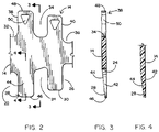
- FIG. 2 is a plan view, with parts broken away, of the polymer panel of the neck brace showing both the first and second preferred embodiments.
- FIG. 3 is a section taken generally along line 3 - 3 of FIG. 2 .
- FIG. 4 is a section taken generally along line 4 - 4 of FIG. 2 .
- FIG. 5 is a plan view similar to FIG. 3 showing the third and fourth preferred embodiments of the progressive flexible tabs of this invention.
- FIG. 6 is an enlarged view taken generally along line 6 - 6 of FIG. 5 showing the edge view of the third and fourth preferred embodiments.
- the orthotic device 10 is an example of several different sizes and shapes of orthotic devices used for the stabilization of portions of the human body.
- a child 12 has the orthotic device engaged around his neck. Such devices are often used when there has been physical stress on a person and it has not been determined if there is spinal injury.
- the orthotic device 10 is particularly configured for the child's neck. Other sizes and shapes of orthotic devices are available in child and adult sizes for stabilization of the back.
- the progressive flexible tabs of this invention are useful in different sizes of orthotic devices configured for the support of different body parts, and the particular orthotic device shown in FIG. 1 is just an example.
- the orthotic device 10 comprise a panel 14 made of suitable synthetic polymer composition material, such as polyethylene, polypropylene or nylon.
- suitable synthetic polymer composition material such as polyethylene, polypropylene or nylon.
- Thermoplastic materials are preferable because they can be formulated to have good flexibility.
- the panel 14 is of sheet material, but this does not necessarily mean it is of uniform thickness. In one embodiment, the panel is cut from a sheet of polymer material of uniform thickness and, in two other embodiments, the panel is molded so that it may have varying thickness.
- the orthotic device 10 also has a chin support 16 . It also has a tightening strap 18 which engages from one end of the panel to the other and engages under the chin support.
- Padding layer 20 underlies the panel 14 and is preferably a synthetic polymer foam panel such as a urethane foam.
- the padding layer is wider than the panel so as to cover the edges of the panel and aid in the support transition.
- the support transition is at the top and bottom edges of the panel where the panel no longer gives support.
- a padding layer of about 0.250 inch thickness is appropriate when the padding layer is a fairly stiff foam.
- the panel 14 may be flat when it is not in service, but is wrapped around a portion of the body to provide orthotic support when it is in use. As seen in FIG. 1 , the panel 14 is curved around an axis which is substantially parallel to the spine of the child 12 , which is up and down in FIG. 1 , parallel to the plane of the sheet.
- the polymer material from which the panel 14 is made is flexible, but not significantly resilient. This means it can bend around one axis, but not bend appreciably at the same time around a different axis. Consequently, when the panel 14 is curved around the upright axis, as shown in FIG. 1 , the edges of the panel cannot bend away.
- the panel is notched at the upper and lower edges.
- Notches 22 , 24 and 26 are cut into the panel along its bottom edge to leave tabs 28 and 30 along the bottom edge.
- notches 32 , 34 and 36 are cut along the top edge to leave tabs 38 and 40 .
- Such tabs are positioned all along the top and bottom edges of the panel. Since these tabs are small in circumferential direction (that is, along the length of the panel around the child's neck), the tabs can bend out away from the cylindrical curvature without significant distortion. This bending eases the transition of loading between the portion of the body constrained by the orthotic device 10 , as compared to the body beyond the edges of the panel.
- the padding layer is principally filling which provides softness for comfort and does not provide significant support.
- the tab is rectangular in plan and of uniform thickness, the bending caused by the load of the padding layer onto the tab does not completely go to zero at the tip of the tab.
- the tab bends away from the loading, but the load does not uniformly decrease and is not zero at the tip of the tab.
- a simple parabolic shape is believed to be the preferred curvature shape of the tab under load and this is not obtained by a tab of uniform cross-section.
- the tabs preferably have a substantially rectangular outline. The reduction in strength from the base of a tab to its tip is accomplished in the first preferred embodiment by tapering the tab to a thinner dimension toward the tip.
- tab 28 has a flat undersurface 42 , which lies in a plane with the remainder of the inside surface of the panel 14 when the panel is laid out flat.
- the top surface 44 is tapered from the bottom of the notch 24 to the tip 46 of the tab.
- the taper of the top surface 44 is preferably uniform to substantially produce the desired parabolic shape when loaded.
- the width of the tab 28 is uniform, but the cross-section is reduced from base to tip by the taper of the tab. This is suitable for a molded panel 14 .
- the other tabs along the lower edge of the panel 14 are of similar construction.
- the tab 38 of the second preferred embodiment is of substantially uniform width and thickness from notch 34 to tip 48 .
- tab 38 has a triangular hole 50 .
- the triangle is an isosceles triangle with its base close to the tip 48 and its apex towards the base of the tab at the bottom of the adjacent notches. Theoretically, the triangle should have its apex at the base of the tab, but it has been found that satisfactory results can be achieved by positioning the triangle with its apex at about one-third to one-half the way from the base to the tip of the tab.
- the base of the triangle is spaced from the tip of the tab sufficiently to leave enough material to support the padding layer properly.
- the tab 38 thus has a reducing cross-section from its base toward its tip so that it is more flexible towards its tip to achieve a more desirable transition in loading. This provides stability of the portion of the body constrained by the orthotic device, together with comfort at the edge of the orthotic device where there is a transition between the restrained and unrestrained portion of the body.
- the panel 52 has notches 54 , 56 and 58 in the edge thereof to define tabs 60 and 62 . Tabs of this construction are formed all across the bottom edge of the panel 52 .
- the flexibility of the tabs in this third preferred embodiment is controlled by the molding of ribs integrally with the panel.
- Ribs 64 and 66 are molded on tab 60 on the side away from the person on whom the orthotic device is to be applied. Two ribs may be applied as shown on tab 60 , while a single rib 68 may be applied as shown on tab 62 in FIGS. 5 and 6 .
- FIG. 6 shows the triangular elevation of the rib above the outer surface of the panel.
- the high point 70 of the rib 66 is about at the bottom of the notches 54 and 56 .
- the rib inclines downwardly toward the outer surface of the panel 52 from the base of the notch to the tip 72 of rib 60 .
- FIG. 5 illustrates that one, two or more ribs may be chosen depending upon structural limitations and desired results.
- the goal of progressively reducing the stiffness of the tabs from their bases to their tips has been accomplished in the above described species is being a progressive reduction in their cross section of the tabs from base to tip.
- Another structure which provides the same result is the reduction in bending strength.
- This is accomplished in the tabs 72 and 74 by making slits or slots through the tabs and across the tabs.
- Tab 72 has a tip 76 which extends outward from notch, which is the main panel of the orthotic device.
- a series of slits 80 is cut through the tab 72 and a series of slits 82 is cut through the tab 74 , as seen in FIG. 5 .
- the slits are in the same triangular outline as the triangular opening 50 .
- the slits prevent bending stress from passing through the slitted area in a direction at a right angkle to the slits.
Abstract
Description
Claims (6)
Priority Applications (1)
| Application Number | Priority Date | Filing Date | Title |
|---|---|---|---|
| US10/104,310 US7470243B2 (en) | 2002-03-22 | 2002-03-22 | Progressive flexible tabs on orthotic devices |
Applications Claiming Priority (1)
| Application Number | Priority Date | Filing Date | Title |
|---|---|---|---|
| US10/104,310 US7470243B2 (en) | 2002-03-22 | 2002-03-22 | Progressive flexible tabs on orthotic devices |
Publications (2)
| Publication Number | Publication Date |
|---|---|
| US20030181838A1 US20030181838A1 (en) | 2003-09-25 |
| US7470243B2 true US7470243B2 (en) | 2008-12-30 |
Family
ID=28040564
Family Applications (1)
| Application Number | Title | Priority Date | Filing Date |
|---|---|---|---|
| US10/104,310 Expired - Lifetime US7470243B2 (en) | 2002-03-22 | 2002-03-22 | Progressive flexible tabs on orthotic devices |
Country Status (1)
| Country | Link |
|---|---|
| US (1) | US7470243B2 (en) |
Cited By (10)
| Publication number | Priority date | Publication date | Assignee | Title |
|---|---|---|---|---|
| US20080319362A1 (en) * | 2007-06-20 | 2008-12-25 | Mark Joseph | Orthopedic System for Immobilizing and Supporting Body Parts |
| USD663851S1 (en) | 2010-08-18 | 2012-07-17 | Exos Corporation | Short thumb spica brace |
| USD663850S1 (en) | 2010-08-18 | 2012-07-17 | Exos Corporation | Long thumb spica brace |
| USD665088S1 (en) | 2010-08-18 | 2012-08-07 | Exos Corporation | Wrist brace |
| USD666302S1 (en) | 2011-12-08 | 2012-08-28 | Exos Corporation | Cervical collar |
| US8491512B2 (en) | 2010-08-26 | 2013-07-23 | Clear Advantage Collar, Inc. | Adjustable cervical collar |
| US8951217B2 (en) | 2009-02-24 | 2015-02-10 | Exos Llc | Composite material for custom fitted products |
| US9295748B2 (en) | 2012-07-31 | 2016-03-29 | Exos Llc | Foam core sandwich splint |
| US9408738B2 (en) | 2012-08-01 | 2016-08-09 | Exos Llc | Orthopedic brace for animals |
| US9655761B2 (en) | 2012-11-12 | 2017-05-23 | Djo, Llc | Orthopedic back brace |
Families Citing this family (19)
| Publication number | Priority date | Publication date | Assignee | Title |
|---|---|---|---|---|
| US7090653B2 (en) * | 2004-09-10 | 2006-08-15 | Carsar, Llc | Cervical collar with curve inducing tab |
| US8182438B2 (en) * | 2007-07-27 | 2012-05-22 | Bio Cybernetics International, Inc. | Orthotic device |
| CN102227196B (en) * | 2008-12-03 | 2013-09-11 | 欧苏尔公司 | Cervical collar having height and circumferential adjustment |
| US8679044B2 (en) | 2008-12-03 | 2014-03-25 | Ossur Hf | Cervical collar with reduced vascular obstruction |
| US10292856B2 (en) | 2009-08-10 | 2019-05-21 | Ossur Hf | Cervical collar having height and circumferential adjustment |
| USD616555S1 (en) | 2009-09-14 | 2010-05-25 | Ossur Hf | Orthopedic device |
| USD616996S1 (en) | 2009-09-14 | 2010-06-01 | Ossur Hf | Orthopedic device |
| USD616997S1 (en) | 2009-09-14 | 2010-06-01 | Ossur Hf | Orthopedic device |
| USD647624S1 (en) | 2010-08-06 | 2011-10-25 | Ossur Hf | Cervical collar |
| USD647623S1 (en) | 2010-08-06 | 2011-10-25 | Ossur Hf | Height adjustment mechanism for cervical collar |
| US9713546B2 (en) | 2012-05-21 | 2017-07-25 | Ossur Hf | Cervical collar |
| WO2016164466A1 (en) | 2015-04-06 | 2016-10-13 | Ossur Iceland Ehf | Cervical collar having height adjustment |
| WO2017147447A1 (en) | 2016-02-25 | 2017-08-31 | Ossur Iceland Ehf | Cervical collar having height adjustment |
| US10945872B2 (en) | 2016-09-19 | 2021-03-16 | Ossur Iceland Ehf | Cervical collar |
| US20190038053A1 (en) * | 2017-08-07 | 2019-02-07 | David E. Brantingham | Travel pillow and methods of use |
| USD870899S1 (en) | 2017-09-06 | 2019-12-24 | Ossur Iceland Ehf | Cervical collar |
| USD866773S1 (en) | 2017-09-06 | 2019-11-12 | Ossur Iceland Ehf | Cervical collar |
| US20200000236A1 (en) * | 2018-06-27 | 2020-01-02 | Frank Wu | Neck Support Article |
| USD1010836S1 (en) | 2023-06-21 | 2024-01-09 | Jing Li | Electronic double chin reducer machine |
Citations (8)
| Publication number | Priority date | Publication date | Assignee | Title |
|---|---|---|---|---|
| US5097824A (en) * | 1990-12-07 | 1992-03-24 | Garth Geoffrey C | Extended wear cervical collar |
| US5366438A (en) * | 1993-05-20 | 1994-11-22 | Martin Sr Bill | Cervical collar |
| US5797713A (en) * | 1995-05-10 | 1998-08-25 | The Jerome Group, Inc. | Orthopedic support unit fastener |
| US5830167A (en) * | 1996-09-19 | 1998-11-03 | Jung; Hyo Sik | Splint for a person with a fractured bone or intervertebral herniated disk |
| US5993403A (en) * | 1993-05-20 | 1999-11-30 | Ambu International A/S | Adjustable cervical collar |
| US6090058A (en) * | 1996-12-23 | 2000-07-18 | Laerdal Medical Corporation | Multiple-size cervical collar |
| US6663581B1 (en) * | 1999-04-09 | 2003-12-16 | Salvatore Calabrese | Cervical collar having multiple sizes |
| US6726643B1 (en) * | 1994-02-22 | 2004-04-27 | Ambu International A/S | Automatic adjustable cervical collar |
-
2002
- 2002-03-22 US US10/104,310 patent/US7470243B2/en not_active Expired - Lifetime
Patent Citations (8)
| Publication number | Priority date | Publication date | Assignee | Title |
|---|---|---|---|---|
| US5097824A (en) * | 1990-12-07 | 1992-03-24 | Garth Geoffrey C | Extended wear cervical collar |
| US5366438A (en) * | 1993-05-20 | 1994-11-22 | Martin Sr Bill | Cervical collar |
| US5993403A (en) * | 1993-05-20 | 1999-11-30 | Ambu International A/S | Adjustable cervical collar |
| US6726643B1 (en) * | 1994-02-22 | 2004-04-27 | Ambu International A/S | Automatic adjustable cervical collar |
| US5797713A (en) * | 1995-05-10 | 1998-08-25 | The Jerome Group, Inc. | Orthopedic support unit fastener |
| US5830167A (en) * | 1996-09-19 | 1998-11-03 | Jung; Hyo Sik | Splint for a person with a fractured bone or intervertebral herniated disk |
| US6090058A (en) * | 1996-12-23 | 2000-07-18 | Laerdal Medical Corporation | Multiple-size cervical collar |
| US6663581B1 (en) * | 1999-04-09 | 2003-12-16 | Salvatore Calabrese | Cervical collar having multiple sizes |
Cited By (20)
| Publication number | Priority date | Publication date | Assignee | Title |
|---|---|---|---|---|
| US9561128B2 (en) | 2007-06-20 | 2017-02-07 | Exos Llc | Orthopedic system for immobilizing and supporting body parts |
| US8303527B2 (en) | 2007-06-20 | 2012-11-06 | Exos Corporation | Orthopedic system for immobilizing and supporting body parts |
| US20080319362A1 (en) * | 2007-06-20 | 2008-12-25 | Mark Joseph | Orthopedic System for Immobilizing and Supporting Body Parts |
| US10463544B2 (en) | 2007-06-20 | 2019-11-05 | Djo, Llc | Orthopedic system for immobilizing and supporting body parts |
| US9757265B2 (en) | 2009-02-24 | 2017-09-12 | Djo, Llc | Composite material for custom fitted products |
| US10940031B2 (en) | 2009-02-24 | 2021-03-09 | Djo, Llc | Composite material for custom fitted products |
| US8951217B2 (en) | 2009-02-24 | 2015-02-10 | Exos Llc | Composite material for custom fitted products |
| USD663850S1 (en) | 2010-08-18 | 2012-07-17 | Exos Corporation | Long thumb spica brace |
| USD665088S1 (en) | 2010-08-18 | 2012-08-07 | Exos Corporation | Wrist brace |
| USD663851S1 (en) | 2010-08-18 | 2012-07-17 | Exos Corporation | Short thumb spica brace |
| US8491512B2 (en) | 2010-08-26 | 2013-07-23 | Clear Advantage Collar, Inc. | Adjustable cervical collar |
| USD666302S1 (en) | 2011-12-08 | 2012-08-28 | Exos Corporation | Cervical collar |
| US10966856B2 (en) | 2012-07-31 | 2021-04-06 | Djo, Llc | Foam core sandwich splint |
| US10285845B2 (en) | 2012-07-31 | 2019-05-14 | Djo, Llc | Foam core sandwich splint |
| US9295748B2 (en) | 2012-07-31 | 2016-03-29 | Exos Llc | Foam core sandwich splint |
| US9408738B2 (en) | 2012-08-01 | 2016-08-09 | Exos Llc | Orthopedic brace for animals |
| US11191627B2 (en) | 2012-08-01 | 2021-12-07 | Djo, Llc | Orthopedic brace for animals |
| US9655761B2 (en) | 2012-11-12 | 2017-05-23 | Djo, Llc | Orthopedic back brace |
| US10517749B2 (en) | 2012-11-12 | 2019-12-31 | Djo, Llc | Orthopedic back brace |
| US11484429B2 (en) | 2012-11-12 | 2022-11-01 | Djo, Llc | Orthopedic back brace |
Also Published As
| Publication number | Publication date |
|---|---|
| US20030181838A1 (en) | 2003-09-25 |
Similar Documents
| Publication | Publication Date | Title |
|---|---|---|
| US7470243B2 (en) | Progressive flexible tabs on orthotic devices | |
| US5230698A (en) | Extended wear cervical collar | |
| US5097824A (en) | Extended wear cervical collar | |
| US5121741A (en) | Shaped halo vest | |
| US5622529A (en) | Flat cervical collar having a unitary chin support | |
| US20080208091A1 (en) | Lower Back Orthosis | |
| US6024715A (en) | Wrist brace | |
| US5788658A (en) | Field adjustable extrication collar | |
| US6494854B1 (en) | Cervical collar device | |
| US4413619A (en) | Portable cervical collar | |
| US6769429B1 (en) | Nasal dilation device | |
| US5346462A (en) | Adjustable tension finger or toe splint | |
| US6115849A (en) | Adjustable strap for scuba mask | |
| EP1299056B1 (en) | Nasal dilator | |
| US5797713A (en) | Orthopedic support unit fastener | |
| US6932782B2 (en) | Flexible splint | |
| US20070006382A1 (en) | Osteopathic pillow | |
| US6027467A (en) | Cervical orthosis | |
| US5782782A (en) | Support belt with corrective angle of lordosis | |
| US6464656B1 (en) | Dynamic arm sling | |
| WO2005060881A1 (en) | Cervical collar with end-supported chin piece | |
| USRE32219E (en) | Portable cervical collar | |
| WO1991004719A1 (en) | Self adjusting, soft neck support collar | |
| JP2007503228A (en) | Multifilament nasal strip released at high peel angle | |
| US20180242747A1 (en) | Head support and method of using the same |
Legal Events
| Date | Code | Title | Description |
|---|---|---|---|
| AS | Assignment |
Owner name: W. G. HOLDING, LLC, A CALIFORNIA LIMITED LIABILITY Free format text: ASSIGNMENT OF ASSIGNORS INTEREST;ASSIGNOR:GARTH, GEOFFREY C.;REEL/FRAME:012733/0670 Effective date: 20020321 |
|
| STCF | Information on status: patent grant |
Free format text: PATENTED CASE |
|
| FPAY | Fee payment |
Year of fee payment: 4 |
|
| FEPP | Fee payment procedure |
Free format text: PAYOR NUMBER ASSIGNED (ORIGINAL EVENT CODE: ASPN); ENTITY STATUS OF PATENT OWNER: SMALL ENTITY |
|
| FPAY | Fee payment |
Year of fee payment: 8 |
|
| AS | Assignment |
Owner name: ASPEN MEDICAL PARTNERS, LLC, CALIFORNIA Free format text: ASSIGNMENT OF ASSIGNORS INTEREST;ASSIGNOR:GARTH, GEOFFREY;REEL/FRAME:049241/0917 Effective date: 20190515 Owner name: ASPEN MEDICAL PARTNERS, LLC, CALIFORNIA Free format text: ASSIGNMENT OF ASSIGNORS INTEREST;ASSIGNOR:GARTH, GEOFFREY;REEL/FRAME:049242/0169 Effective date: 20190515 |
|
| AS | Assignment |
Owner name: ANTARES CAPITAL LP, AS AGENT, ILLINOIS Free format text: SECURITY INTEREST;ASSIGNORS:ASPEN MEDICAL HOLDINGS, LLC;ASPEN MEDICAL PARTNERS, LLC;CARSAR, LLC;AND OTHERS;REEL/FRAME:049417/0331 Effective date: 20190610 |
|
| AS | Assignment |
Owner name: FIJI MANUFACTURING, LLC, CALIFORNIA Free format text: ASSIGNMENT OF ASSIGNORS INTEREST;ASSIGNOR:ASPEN MEDICAL PARTNERS, LLC;REEL/FRAME:051982/0246 Effective date: 20200227 Owner name: FIJI MANUFACTURING, LLC, CALIFORNIA Free format text: ASSIGNMENT OF ASSIGNORS INTEREST;ASSIGNOR:WG HOLDINGS, LLC;REEL/FRAME:051982/0524 Effective date: 20200227 |
|
| MAFP | Maintenance fee payment |
Free format text: PAYMENT OF MAINTENANCE FEE, 12TH YR, SMALL ENTITY (ORIGINAL EVENT CODE: M2553); ENTITY STATUS OF PATENT OWNER: SMALL ENTITY Year of fee payment: 12 |