US7450636B2 - Adaptive transmit equalizer - Google Patents
Adaptive transmit equalizer Download PDFInfo
- Publication number
- US7450636B2 US7450636B2 US10/235,357 US23535702A US7450636B2 US 7450636 B2 US7450636 B2 US 7450636B2 US 23535702 A US23535702 A US 23535702A US 7450636 B2 US7450636 B2 US 7450636B2
- Authority
- US
- United States
- Prior art keywords
- vertex
- simplex
- equalizer
- receiver
- transmitter
- Prior art date
- Legal status (The legal status is an assumption and is not a legal conclusion. Google has not performed a legal analysis and makes no representation as to the accuracy of the status listed.)
- Expired - Fee Related, expires
Links
Images


Classifications
-
- H—ELECTRICITY
- H03—ELECTRONIC CIRCUITRY
- H03H—IMPEDANCE NETWORKS, e.g. RESONANT CIRCUITS; RESONATORS
- H03H21/00—Adaptive networks
- H03H21/0012—Digital adaptive filters
- H03H21/0043—Adaptive algorithms
-
- H—ELECTRICITY
- H04—ELECTRIC COMMUNICATION TECHNIQUE
- H04L—TRANSMISSION OF DIGITAL INFORMATION, e.g. TELEGRAPHIC COMMUNICATION
- H04L25/00—Baseband systems
- H04L25/02—Details ; arrangements for supplying electrical power along data transmission lines
- H04L25/03—Shaping networks in transmitter or receiver, e.g. adaptive shaping networks
- H04L25/03006—Arrangements for removing intersymbol interference
- H04L25/03343—Arrangements at the transmitter end
-
- H—ELECTRICITY
- H04—ELECTRIC COMMUNICATION TECHNIQUE
- H04L—TRANSMISSION OF DIGITAL INFORMATION, e.g. TELEGRAPHIC COMMUNICATION
- H04L25/00—Baseband systems
- H04L25/02—Details ; arrangements for supplying electrical power along data transmission lines
- H04L25/03—Shaping networks in transmitter or receiver, e.g. adaptive shaping networks
- H04L25/03006—Arrangements for removing intersymbol interference
- H04L2025/03592—Adaptation methods
- H04L2025/03598—Algorithms
- H04L2025/03611—Iterative algorithms
Definitions
- the present invention generally relates to data communications, and more particularly to equalization techniques in data communications.
- Digital systems typically transmit data as symbols having discrete levels of amplitude and/or phase. To the extent that a symbol is received at a level that differs from one of the allowed discrete levels, a measure of communication channel error can be detected.
- An equalizer is typically a filter that has the inverse characteristics of the communication channel. If the transmission characteristics of the communication channel are known or measured, then the equalization filter parameters can be set directly. After adjustment of the equalization filter parameters, the received signal is passed through the equalizer, which compensates for the non-ideal communication channel by introducing compensating “distortions” into the received signal, which tend to cancel the distortions introduced by the communication channel.
- Equalization in existing communication systems is usually done in one of three ways.
- the transmitter includes a non-adaptive equalizer.
- the receiver includes a non-adaptive equalizer.
- the receiver includes an adaptive equalizer.
- non-adaptive equalizer The most commonly used method in high-speed transmission systems is to use a non-adaptive equalizer.
- optimizing performance requires manual tuning with detailed a priori knowledge of the channel.
- the non-adaptive equalizer can be set for a generic channel, such an approach often leads to sub-optimal performance, since all channels do not have exactly the same characteristics as the generic channel.
- a non-adaptive equalizer will result in sub-optimal performance even if the equalizer was initially tuned optimally.
- each receiver is in a unique location with respect to the transmitter. Accordingly, the characteristics of the communication channel are not known in advance, and may even change with time. In those situations, where the communication channel is not characterized in advance, or changes with time, an adaptive equalizer in the receiver is typically used. Adaptive equalizers have variable parameters that are calculated in the receiver. A problem to be solved in an adaptive equalizer is how to adjust the equalizer filter parameters in order to restore signal quality to an acceptable performance level.
- the parameters of the receiver equalization filter are set using a predetermined pilot signal (a training sequence), which is periodically sent from the transmitter to the receiver.
- the received training sequence is compared with a known training sequence to derive the parameters of the equalization filter. After several iterations of parameter settings derived from successive training sequences, the receiver equalization filter converges to a setting that tends to compensate for the distortion characteristics of the communications channel.
- the parameters of the receiver equalizer filter are typically derived from the received signal itself without using a training sequence.
- the equalizer parameters are adjusted using a Least Mean Squares (LMS) algorithm, in which the training symbols are replaced with hard decisions, or best estimates of the original input symbols.
- LMS Least Mean Squares
- RLS Recursive Least Squares
- CMA Constant Modulus Algorithm
- One form of the present invention provides an adaptive transmit equalizer for equalizing digital symbols to be transmitted over a communications channel.
- the equalizer includes a transmit filter having an associated register for storing at least one filter coefficient.
- a tuning engine generates performance metric values based on digital symbols received through the communications channel.
- the tuning engine is configured to identify at least one filter coefficient based on the performance metric values using a simplex algorithm.
- the tuning engine is configured to communicate the at least one updated filter coefficient to the transmit filter for storage in the register.
- FIG. 1 is block diagram illustrating a prior art communication system.
- FIG. 2 is a block diagram illustrating major components of a communication system with an adaptive transmit equalizer according to one embodiment of the present invention.
- FIG. 3 is a block diagram illustrating major components of the receiver shown in FIG. 2 according to one embodiment of the present invention.
- FIG. 4 is a flow diagram of a simplex algorithm for updating filter coefficients for an equalizer according to one embodiment of the present invention.
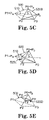
- FIGS. 5A-5E are diagrams illustrating example simplex structures, and reflection, extension, and contraction operations, according to one embodiment of the present invention.
- FIG. 1 is block diagram illustrating a prior art communication system 100 .
- the system 100 includes a transmitter 102 and a receiver 106 , which are coupled together via a suitable communication channel 104 .
- the frequency response of a communication channel is not ideal.
- the channel causes distortion of the signal transmitted by transmitter 102 .
- Such distortion can give rise to effects such as intersymbol interference (ISI), which prevents the receiver 106 from accurately distinguishing adjacent received data symbols from one another.
- ISI intersymbol interference
- Intersymbol interference occurs when the signal for one bit interferes with the signal for an adjacent bit.
- an equalizer may be used in communication systems to compensate for distortions caused by the channel.
- Non-adaptive equalizers have been used in transmitters, and both adaptive and non-adaptive equalizers have been used in receivers of communication systems.
- One embodiment of the present invention is described in terms of functional block components and various method steps. It will be understood by persons of ordinary skill in the art that such functional blocks may be realized by any number of hardware components configured to perform the specified functions. For example, embodiments of the present invention may employ various integrated circuit components (e.g., memory elements, digital signal processing elements, look-up tables, and the like), which may carry out a variety of functions under the control of one or more microprocessors or other control devices. In addition, those skilled in the art will appreciate that the present invention may be practiced in any number of data communication contexts.
- integrated circuit components e.g., memory elements, digital signal processing elements, look-up tables, and the like
- FIG. 2 is a block diagram illustrating major components of a communication system 200 with an adaptive transmit equalizer 204 according to one embodiment of the present invention.
- System 200 includes transmitter 202 , channel 206 , receiver 208 , and return link 214 .
- system 200 is a high-speed communication system that operates at between about 5 to 10 gigabits/second. In other embodiments, other data rates are used.
- Transmitter 202 includes an adaptive transmit equalizer 204 .
- Equalizer 204 includes storage register 205 .
- equalizer 204 is a finite impulse response (FIR) digital filter equalizer having filtering coefficients (or filter parameters or tap weights) stored in storage register 205 .
- Equalizer 204 may be constructed in a variety of ways, including in integrated circuit form as a multiple-tap, FIR digital filter with programmable tap weights, or with a sequence of program instructions performable by a processor or digital signal processor (DSP), and/or by custom logic circuitry.
- FIR finite impulse response
- data to be transmitted is equalized prior to transmission by equalizer 204 .
- the letter “n” in a(n) is an index value for identifying each data element.
- each a(n) represents a digital symbol.
- each a(n) represents either a+1 or a ⁇ 1.
- other symbol values are used (e.g., +1, ⁇ 1, +3, and ⁇ 3).
- the sequence of digital symbols, a(n), is equalized by equalizer 204 to produce an equalized output x(n).
- Equalizer 204 filters the symbols, a(n), to compensate for signal distortion that will be introduced by the communications channel 206 .
- the equalizer 204 pre-shapes or pre-distorts the signal to be transmitted, so that when the channel 206 distorts the signal, the channel 206 essentially “fixes” the signal.
- the output x(n) of equalizer 204 is defined by the following Equation I:
- channel 206 is a high-speed backplane channel. Primary sources of distortion for such channels include attenuation due to skin loss and dielectric loss. In another embodiment, channel 206 represents a communication path for cable modem communications. Although a couple of examples of channel types have been provided, it will be understood by persons of ordinary skill in the art that the techniques described herein are applicable to virtually any type of two-way communication system.
- Receiver 208 includes a tuning engine 210 .
- received samples are used by tuning engine 210 to determine a new set of filter parameters for equalizer 204 .
- tuning engine 210 uses a simplex algorithm 316 (shown in FIG. 4 ) to determine a new set of filter parameters, as described in further detail below with reference to FIG. 4 .
- the new set of filter parameters is sent from receiver 208 back to the transmitter 202 via return link 214 .
- the contents of the equalizer storage register 205 are updated based on the received set of new filter parameters.
- the filter coefficients of the equalizer 204 are automatically adjusted by tuning engine 210 to optimize the transmitted signal for minimum intersymbol interference.
- return link 214 is part of channel 206 as indicated by the dotted lines in FIG. 2 .
- return link 214 is a separate line coming back from the receiver 208 to the transmitter 202 .
- return link 214 is a single separate line that is shared among many pairs of transmitters and receivers, such as transmitter 202 and receiver 208 .
- tuning engine 210 transmits equalizer parameter update information to transmitter 202 over return link 214 at a relatively low rate. In one embodiment, approximately 50 to 100 kilo-samples (kS) per second are transmitted over return link 214 .
- the low rate transmission helps to ensure that the parameter update information will be received accurately at transmitter 202 .
- the parameter update information is embedded in other data being sent from receiver 208 to transmitter 202 .
- Other embodiments may use higher rates of transmission for returning parameter update information to transmitter 202 .
- FIG. 3 is a block diagram illustrating major components of the receiver 208 shown in FIG. 2 according to one embodiment of the present invention.
- Receiver 208 includes filter 302 , automatic gain control (AGC) 304 , clock/data recover block 306 , tuning engine 210 , and slicer 312 .
- AGC automatic gain control
- Filter 302 , AGC 304 , and clock/data recovery block 306 are used to Recover y(n), which are samples corresponding to the transmitted symbols a(n).
- filter 302 is a low-pass filter for filtering out noise in the received signal.
- AGC 304 adjusts the gain of the signal output by filter 302 .
- AGC 304 senses the power in the signal received from filter 302 , and if the power is below a given threshold, AGC 304 increases the power of the signal. If the power is above a given threshold, AGC 304 decreases the power of the signal.
- AGC 304 outputs a gain-adjusted signal to clock/data recover block 306 .
- Clock/data recovery block 306 includes circuitry to recover a clock signal from the signals received from AGC 304 , relative to a receiver clock (not shown) in a conventional manner known to those of ordinary skill in the art.
- Clock/data recovery block 306 outputs digital samples, y(n), of the received signal.
- Slicer 312 is a decision device that receives a sequence of samples y(n) from clock/data recovery block 306 and, based on a conventional slicing algorithm, determines and outputs a corresponding sequence of symbols â(n) to tuning engine 210 .
- the signals a(n) to be transmitted are binary signals represented by +1 or ⁇ 1.
- each value for y(n) may not be exactly +1 or ⁇ 1.
- values for y(n) might be 0.8, 1.1, ⁇ 0.9, etc.
- slicer 312 makes a decision on what the original symbol a(n) was, and outputs that ideal symbol value (e.g., +1 or ⁇ 1 in one embodiment), which is represented by â(n).
- tuning engine 210 includes a controller 308 and an error calculator 310 .
- tuning engine 210 is implemented with a microprocessor and software appropriate for directing the microprocessor to perform the tuning functions described herein.
- MSE 309 is the performance metric that drives simplex algorithm 316 according to one embodiment.
- MSE 309 is estimated by averaging [y(n) ⁇ â(n)] 2 over several samples of y(n) and â(n).
- the input y(n) and the output â(n) of slicer 312 are substantially equal and, consequently, the MSE 309 would be zero.
- controller 308 Based on the MSE 309 calculated by error calculator 310 , controller 308 adaptively adjusts operational characteristics of equalizer 204 to optimize the performance of system 200 . In one embodiment, controller 308 determines new filter parameters W k for the equalizer 204 using simplex algorithm 316 stored in memory 314 of controller 308 .
- controller 308 After calculating updated filter coefficients, these updated filter coefficients are transmitted to the transmitter 202 via return link 214 and loaded into the register 205 of equalizer 204 .
- controller 308 continually adjusts the filter coefficients of the equalizer 204 in accordance with the MSE 309 supplied by the error calculator 310 . In one embodiment, once the MSE 309 converges to an acceptable value, equalizer 204 is considered to be adequately trained. In an alternative embodiment, controller 308 periodically or continuously provides updated filter coefficients to equalizer 204 to adjust for changing channel conditions.
- FIG. 4 is a flow diagram of a simplex algorithm 316 for updating filter coefficients of equalizer 204 according to one embodiment of the present invention.
- Algorithm 316 will also be described with reference to FIGS. 5A-5E , which are diagrams illustrating example simplex structures, and reflection, extension, and contraction operations, according to one embodiment of the present invention.
- simplex algorithm is performed by controller 308 (shown in FIG. 3 ).
- simplex algorithm 316 does not use derivatives, but rather uses a “simplex” to find reasonable directions when searching a performance surface.
- a “simplex,” according to one form of the invention, is a geometric object with straight edges connecting a finite number of vertices (points in N space) and is defined in an N-dimensional space (for example, in 2 dimensions, it would be a polygon, like a square, and in 3 dimensions it might be a cube, etc.).
- Simplex methods are discussed in J. A. Nelder and R. Mead, A Simplex Method for Function Minimization, Computer Journal, v. 7, p. 308, 1965, and W. H. Press, B. P. Flannery, S. A. Teukolsky and W. T. Vetterling, Numerical Recipes, Cambridge, 1986, which are hereby incorporated by reference herein.
- FIG. 5A is a diagram illustrating an example initial simplex 500 .
- Simplex 500 includes four vertices P 0 -P 3 , with straight edges connecting the vertices.
- controller 308 associates each vertex in the initial simplex 500 with a set of trial filter parameters that define the position of the vertex in N-space.
- the initial simplex includes N+1 vertices, P 0 , P 1 , P 2 , . . . , PN.
- each of the vertices P 1 -PN is generated from vertex P 0 by varying (e.g., randomly) one of the parameters of P 0 .
- delta is randomly chosen for each vertex.
- Steps 410 - 440 are a repeating loop for iteratively searching the performance surface for the best set of parameters.
- the variable “cnt” tracks the number of iterations and the variable “max_cnt” specifies the maximum number of iterations.
- cnt is initialized by being set to zero.
- a new simplex is generated by replacing the worst vertex in the current simplex with at least one better vertex as described below.
- a “reflection” is computed.
- the “worst” vertex in the simplex is determined by ranking all of the vertices based on performance metric values.
- Each vertex in the simplex is associated with a performance metric value.
- the performance metric value for each vertex is determined during an initialization phase by first setting the filter coefficients of equalizer 204 to values corresponding to the first vertex, and determining the MSE 309 . The filter coefficients of equalizer 204 are then set to values corresponding to the second vertex, and the MSE 309 is determined. This process is repeated for each vertex in the simplex.
- the performance metric value for each vertex is stored in memory 314 once it has been determined.
- FIG. 5B is a diagram illustrating the example initial simplex 500 shown in FIG. 5A , with a reflection vertex, P R .
- the initial simplex 500 is illustrated with broken lines in FIG. 5B .
- FIG. 5B is a diagram illustrating the example initial simplex 500 shown in FIG. 5A , with a reflection vertex, P R .
- the initial simplex 500 is illustrated with broken lines in FIG. 5B .
- vertex P 1 has been identified as the worst vertex P W
- vertex P 0 has been identified as the best vertex P B
- a line 510 has been drawn from the worst vertex P 1 through the centroid, C, of the simplex that excludes the worst vertex (i.e., the simplex formed by vertices P 0 , P 2 , and P 3 ). Since the worst vertex P W in the current simplex is known, controller 308 “looks” for a reflection vertex P R in the “opposite direction” from the worst vertex P W . As shown in FIG. 5B , the “opposite direction” from the worst vertex P W is the direction defined by the line 510 from the worst vertex P W through the centroid C of the simplex without the worst vertex.
- the position of the reflection vertex P R depends on the value of ⁇ in Equation III.
- ⁇ is chosen so that the reflection vertex P R is on the far side of the centroid C away from the worst vertex P W as shown in FIG. 5B .
- the set of parameters (i.e., parameter vector) for the new vertex, Pr is determined using Equation III.
- c( 2 ) (p 0 ( 2 )+p 1 ( 2 )+p 2 ( 2 ), . . . , +pN( 2 ))/N, etc., where the parameters for the worst vertex P W are excluded from the calculation of c( 1 ), c( 2 ), . . . , c(N)).
- controller 308 determines in step 418 whether the reflection P R is better than the best vertex P B . In one embodiment, this determination is made by first setting the filter coefficients of equalizer 204 to the values corresponding to the parameters of the reflection vertex P R , and determining the performance metric value (e.g., MSE 309 ). This performance metric value for P R is stored in memory 314 , and is compared to the performance metric value for the best vertex P B . If the performance metric value for P R is better than the performance metric value for P B , controller 308 moves to step 416 . If the performance metric value for P R is not better than the performance metric value for P B , controller 308 moves to step 420 .
- the performance metric value for P R is stored in memory 314 , and is compared to the performance metric value for the best vertex P B . If the performance metric value for P R is better than the performance metric value for P B , controller 308 moves to step 416 . If the performance
- an “extension” is computed.
- FIG. 5C is a diagram illustrating the example initial simplex 500 shown in FIG. 5A , with an extension vertex, P E .
- the initial simplex 500 is illustrated with broken lines in FIG. 5C .
- a line 510 has been drawn from the worst vertex P 1 through the centroid, C, of the simplex that excludes the worst vertex (i.e., the simplex formed by vertices P 0 , P 2 , and P 3 ).
- P E is called an extension because it is in the same direction as the line 510 going from the worst vertex P 1 to the reflection vertex P R (shown in FIG. 5B ), only it extends farther than the reflection.
- a rationale for the extension is that if going from the worst vertex P 1 to P R is good, then going from the worst vertex P 1 to P E might be even better.
- controller 308 determines whether the extension P E is better than the best vertex P B . In one embodiment, this determination is made by first setting the filter coefficients of equalizer 204 to the values corresponding to the parameters of the extension vertex P E , and determining the performance metric value (e.g., MSE 309 ). This performance metric value for P E is stored in memory 314 , and is compared to the performance metric value for the best vertex P B . If the performance metric value for P E is not better than the performance metric value for P B , controller 308 moves to step 434 . In step 434 , the worst vertex P W is replaced by the reflection vertex P R to generate a new simplex. As shown in FIG.
- the worst vertex (i.e., P 1 ) in the initial simplex 500 is replaced by the reflection vertex P R to generate a new simplex 520 A, which includes vertices P 0 , P 2 , P 3 , and P R .
- algorithm 316 jumps to decision block 410 .
- step 426 If it is determined in step 426 that the performance metric value for P E is better than the performance metric value for P B , controller 308 moves to step 428 .
- step 428 the worst vertex P W is replaced by the extension vertex P E to generate a new simplex.
- the worst vertex (i.e., P 1 ) in the initial simplex 500 is replaced by the extension vertex P E to generate a new simplex 520 B, which includes vertices P 0 , P 2 , P 3 , and P E .
- algorithm 316 jumps to decision block 410 .
- controller 308 moves to step 420 , and determines whether the reflection P R is better than the second worst vertex. If the reflection P R is better than the second worst vertex, in step 430 , controller 308 replaces the worst vertex P W with the reflection vertex P R to generate a new simplex (e.g., simplex 520 A shown in FIG. 5B ). After step 430 , algorithm 316 jumps to decision block 410 .
- controller 308 determines whether the reflection P R is better than the worst vertex P W . If it is determined in step 422 that the reflection P R is not better than the worst vertex P W , controller 308 moves to step 432 . If it is determined in step 422 that the reflection P R is better than the worst vertex P W , in step 424 , controller 308 replaces the worst vertex P W with the reflection vertex P R to generate a new simplex (e.g., simplex 520 A shown in FIG. 5B ), and moves to step 432 .
- a new simplex e.g., simplex 520 A shown in FIG. 5B
- a contraction is computed.
- FIG. 5D is a diagram illustrating the example initial simplex 500 shown in FIG. 5A , with a contraction vertex, P C .
- the initial simplex 500 is illustrated with broken lines in FIG. 5D .
- a line 510 has been drawn from the worst vertex P 1 through the centroid, C, of the simplex that excludes the worst vertex (i.e., the simplex formed by vertices P 0 , P 2 , and P 3 ).
- P C is called a contraction because it is in the same direction as the line 510 going from the worst vertex P 1 to the reflection vertex P R , only it does not extend as far as the reflection.
- a rationale for the contraction is that if going from the worst vertex P 1 to P R is good (e.g., because it is in the opposite direction from the worst vertex P 1 ), then maybe going all the way to P R may be too far, and stopping at P C may be better.
- controller 308 determines whether the contraction vertex P C is better than the worst vertex P W . In one embodiment, this determination is made by first setting the filter coefficients of equalizer 204 to the values corresponding to the parameters of the contraction vertex P C , and determining the performance metric value (e.g., MSE 309 ). This performance metric value for P C is stored in memory 314 , and is compared to the performance metric value for the worst vertex P W . If the performance metric value for P C is better than the performance metric value for P W , controller 308 moves to step 440 . In step 440 , the worst vertex P W is replaced by the contraction vertex P C to generate a new simplex. As shown in FIG.
- the worst vertex (i.e., P 1 ) in the initial simplex 500 is replaced by the contraction vertex P C to generate a new simplex 520 C, which includes vertices P 0 , P 2 , P 3 , and P C .
- algorithm 316 jumps to decision block 410 .
- step 436 If it is determined in step 436 that the performance metric value for P C is not better than the performance metric value for P W , controller 308 moves to step 438 .
- step 438 the current simplex is contracted around the best vertex P B .
- FIG. 5E is a diagram illustrating the example initial simplex 500 shown in FIG. 5A , contracted around the best vertex P 0 to generate a new simplex 520 D, which includes vertices P 0 , P 1 ′, P 2 ′, and P 3 ′.
- the initial simplex 500 is illustrated with broken lines in FIG. 5E .
- Each of the vertices Pk in the initial simplex 500 other than the best vertex P B e.g., vertices P 1 , P 2 , and P 3
- vertices Pk′ e.g., vertices P 1 ′, P 2 ′, and P 3 ′
- each vertex Pk′ is generated in one embodiment by adding the best vertex P B to the vertex Pk from the initial simplex 500 , and dividing the result by two.
- a rationale for contracting the simplex about the best vertex is that the best vertex might be near an optimum, or the simplex might have to be contracted to get through a keyhole in an N-dimensional performance surface.
- the performance metric values for each of the new vertices Pk′ in the new simplex 520 D are determined by setting the filter coefficients of equalizer 204 to the values corresponding to the parameter vectors of each of these vertices and determining the MSE 309 .
- algorithm 316 jumps to decision block 410 .
- algorithm 316 may be restarted using the best filter parameters found so far as the initial guess. If the parameters truly are the best, the algorithm 316 should again converge to the same settings. However, if the initial results only identified a local optimum, restarting the algorithm 316 may result in a better, perhaps global, optimum being found.
- algorithm 316 is used for “on-line” adaptation. That is, after initial training, tuning engine 210 continues to use algorithm 316 to adjust to changing channel conditions.
- Performance metrics other than (or in addition to) the mean square error of y(n) and â(n) may be used to drive simplex algorithm 316 .
- the transmitted data a(n) is known by receiver 208 (e.g., such as a known training sequence)
- the mean square error performance metric 309 could be computed using a(n) instead of â(n).
- the performance metric 309 could be vertical eye opening.
- the performance metric 309 could be generated by estimating the eye opening using y(n). For instance, with binary signaling, the nominal values for a(n) are +1/ ⁇ 1.
- the vertical eye opening case for multi-level symbols is similar to the above-described binary symbol case.
- the performance metric 309 could also be clock jitter.
- a clock jitter performance metric can be generated using a circuit that measures the variance of the clock jitter. In one embodiment, this measuring circuit would be a part of the clock/data recovery block 306 .
- the performance metric 309 could also be a weighted combination of individual performance metrics, such as mean square error (or vertical eye opening) and clock jitter.
- an advantage of one form of the present invention is that the tuning engine 210 is based on a simplex algorithm rather than the commonly used LMS algorithm.
- the LMS algorithm one of the inputs to the algorithm is the unequalized channel output samples. This means that, to implement an adaptive transmit equalizer with the LMS algorithm, there must either be a copy of the equalizer in the receiver, or there must be a means to reconstruct the unequalized channel output samples. Although this can be done, it is not practical given the receiver constraints and expected data rates. This issue is avoided with one embodiment of the present invention, which uses a simplex algorithm.
- the LMS algorithm is based solely on mean square error as the performance metric, whereas one form of the present invention is easily modified to use other performance metrics (e.g., minimizing a combination of mean square error and clock jitter).
- one embodiment of the present invention provides an adaptive equalizer in the transmitter, which has advantages over approaches that implement the equalizer in the receiver. For example, since the equalizer is implemented in the transmitter in one embodiment, the problem of noise enhancement associated with receiver equalization is avoided.
Abstract
Description
-
- where:
- wk(n) is the kth tap weight of
equalizer 204 at time n; and - L is the length of equalizer 204 (i.e., the number of tap weights in equalizer 204).
- wk(n) is the kth tap weight of
- where:
MSE=[y(n)−â(n)]2 Equation II
P R=(1+α)C−αP W Equation III
-
- where:
- PR is the reflection vertex;
- α is a reflection coefficient, which is a positive constant in one embodiment;
- PW is the “worst” vertex in the current simplex; and
- C is the centroid of the current simplex excluding PW
- where:
P E =γP R+(1−γ)C Equation IV
-
- where:
- PE is the extension vertex;
- γ is an extension coefficient, which is a positive constant greater than unity in one embodiment;
- PR is the reflection vertex calculated from Equation III; and
- C is the centroid of the current simplex excluding PW
- where:
P C =βP W(1−β)C Equation V
-
- where:
- PC is the contraction vertex;
- β is a contraction coefficient, which is a constant between 0 and 1 in one embodiment;
- PW is the worst vertex in the current simplex; and
- C is the centroid of the current simplex excluding PW
- where:
Pk′=(Pk+P B)/2 Equation VI
-
- where:
- Pk is the kth vertex in the current simplex;
- PB is the best vertex in the current simplex; and
- Pk′ is the kth vertex in the new, contracted simplex.
- where:
Claims (25)
Priority Applications (3)
| Application Number | Priority Date | Filing Date | Title |
|---|---|---|---|
| US10/235,357 US7450636B2 (en) | 2002-09-05 | 2002-09-05 | Adaptive transmit equalizer |
| DE10329661A DE10329661B4 (en) | 2002-09-05 | 2003-07-01 | Adaptive transmitter equalizer |
| JP2003311785A JP2004104781A (en) | 2002-09-05 | 2003-09-03 | Optimizing method of adaptive transmit equalizer and filter parameter |
Applications Claiming Priority (1)
| Application Number | Priority Date | Filing Date | Title |
|---|---|---|---|
| US10/235,357 US7450636B2 (en) | 2002-09-05 | 2002-09-05 | Adaptive transmit equalizer |
Publications (2)
| Publication Number | Publication Date |
|---|---|
| US20040047409A1 US20040047409A1 (en) | 2004-03-11 |
| US7450636B2 true US7450636B2 (en) | 2008-11-11 |
Family
ID=31887697
Family Applications (1)
| Application Number | Title | Priority Date | Filing Date |
|---|---|---|---|
| US10/235,357 Expired - Fee Related US7450636B2 (en) | 2002-09-05 | 2002-09-05 | Adaptive transmit equalizer |
Country Status (3)
| Country | Link |
|---|---|
| US (1) | US7450636B2 (en) |
| JP (1) | JP2004104781A (en) |
| DE (1) | DE10329661B4 (en) |
Cited By (14)
| Publication number | Priority date | Publication date | Assignee | Title |
|---|---|---|---|---|
| US20080159372A1 (en) * | 2006-12-28 | 2008-07-03 | Intel Corporation | Automatic tuning circuit for a continuous-time equalizer |
| US20100128763A1 (en) * | 2007-08-03 | 2010-05-27 | Fujitsu Limited | Communication device, communication system, and communication method |
| US9313056B1 (en) * | 2014-11-07 | 2016-04-12 | Dell Products, Lp | System aware transmitter adaptation for high speed serial interfaces |
| US9674013B2 (en) | 2014-09-19 | 2017-06-06 | Dell Products, Lp | Enhanced receiver equalization |
| US9930771B2 (en) | 2015-12-16 | 2018-03-27 | Dell Products, Lp | Aperiodic routing to mitigate floquet mode resonances |
| US9942935B2 (en) | 2015-11-17 | 2018-04-10 | Dell Products, Lp | System and method for providing a wireless failover of a management connection in a server rack of a data center |
| US9996646B2 (en) | 2014-09-23 | 2018-06-12 | Dell Products, Lp | System and method of determining high speed resonance due to coupling from broadside layers |
| US10116744B2 (en) | 2016-02-04 | 2018-10-30 | Dell Products, Lp | System and method for providing management network communication and control in a data center |
| US10216681B2 (en) | 2015-12-01 | 2019-02-26 | Dell Products, Lp | System and method for managing workloads and hot-swapping a co-processor of an information handling system |
| US10241555B2 (en) | 2015-12-04 | 2019-03-26 | Dell Products, Lp | System and method for monitoring a battery status in a server in a data center |
| US10298460B2 (en) | 2015-12-21 | 2019-05-21 | Dell Products, Lp | System and method for aggregating communication and control of wireless end-points in a data center |
| US10373283B2 (en) | 2016-03-14 | 2019-08-06 | Dell Products, Lp | System and method for normalization of GPU workloads based on real-time GPU data |
| US10728061B2 (en) | 2018-06-18 | 2020-07-28 | Samsung Electronics Co., Ltd. | Electronic devices including equalizers operating based on coefficients adjusted in training operations |
| WO2022227099A1 (en) * | 2021-04-30 | 2022-11-03 | 华为技术有限公司 | Sending device, receiving device, and signal compensation method |
Families Citing this family (26)
| Publication number | Priority date | Publication date | Assignee | Title |
|---|---|---|---|---|
| ATE398363T1 (en) * | 2002-01-29 | 2008-07-15 | Nokia Corp | DATA TRANSFER METHOD IN A RADIO SYSTEM |
| JP3852772B2 (en) * | 2002-11-29 | 2006-12-06 | 富士通株式会社 | Recording medium playback equalizer training method and recording medium playback device |
| US7346094B2 (en) * | 2002-12-13 | 2008-03-18 | International Business Machines Corporation | System and method for transmitting data and additional information simultaneously within a wire based communication system |
| KR100509949B1 (en) * | 2003-11-19 | 2005-08-24 | 한국전자통신연구원 | Data transmitting/receiving apparatus and method for performing equalization and pre-emphasis adaptive to transmission characteristics of receiving side |
| US7940839B2 (en) * | 2004-01-26 | 2011-05-10 | Diablo Technologies Inc. | Fully adaptive equalization for high loss communications channels |
| US7295618B2 (en) * | 2004-06-16 | 2007-11-13 | International Business Machines Corporation | Automatic adaptive equalization method and system for high-speed serial transmission link |
| JP4605637B2 (en) * | 2004-07-29 | 2011-01-05 | 株式会社日立製作所 | Storage device system and signal transmission method in storage device system |
| US7516226B2 (en) * | 2004-09-30 | 2009-04-07 | Agere Systems Inc. | Transmit adaptive equalization using ordered sets |
| US7378649B2 (en) * | 2005-10-17 | 2008-05-27 | Varian, Inc. | Simplex optimization methods for instrumentation tuning |
| US7660349B2 (en) * | 2005-12-30 | 2010-02-09 | Intel Corporation | Transmit equalizer compensation for probe receivers |
| US7986727B2 (en) * | 2006-03-28 | 2011-07-26 | Globalfoundries Inc. | In-band method to configure equalization levels |
| US8570881B2 (en) * | 2006-03-28 | 2013-10-29 | Advanced Micro Devices, Inc. | Transmitter voltage and receiver time margining |
| US7817727B2 (en) * | 2006-03-28 | 2010-10-19 | GlobalFoundries, Inc. | Hybrid output driver for high-speed communications interfaces |
| WO2008070138A2 (en) | 2006-12-05 | 2008-06-12 | Rambus Inc. | Methods and circuits for asymmetric distribution of channel equalization between transceiver devices |
| WO2008150321A1 (en) | 2007-05-25 | 2008-12-11 | Rambus Inc. | Methods and systems for transmitting auxiliary data by modulating pre-emphasis filter coefficients |
| US8406356B2 (en) * | 2007-06-06 | 2013-03-26 | Micron Technology, Inc. | Self-calibrating continuous-time equalization |
| US8018992B2 (en) * | 2007-10-31 | 2011-09-13 | Intel Corporation | Performing adaptive external equalization |
| US8452829B2 (en) * | 2008-06-23 | 2013-05-28 | Oracle America, Inc. | Real-time optimization of TX FIR filter for high-speed data communication |
| US8514925B2 (en) * | 2008-07-23 | 2013-08-20 | Agere Systems Llc | Methods and apparatus for joint adaptation of transmitter transversal filter in communication devices |
| JP5670622B2 (en) * | 2009-04-23 | 2015-02-18 | ザインエレクトロニクス株式会社 | Transmission device, reception device, transmission / reception system, and image display system |
| US8918503B2 (en) | 2011-12-06 | 2014-12-23 | Seven Networks, Inc. | Optimization of mobile traffic directed to private networks and operator configurability thereof |
| US8902964B2 (en) | 2012-09-29 | 2014-12-02 | Intel Corporation | Equalization effort-balancing of transmit finite impulse response and receive linear equalizer or receive decision feedback equalizer structures in high-speed serial interconnects |
| US9071477B2 (en) * | 2013-10-09 | 2015-06-30 | Global Unichip Corporation | Method and associated processing module for interconnection system |
| US9882748B2 (en) * | 2014-03-10 | 2018-01-30 | Intel Corporation | Technologies for configuring transmitter equalization in a communication system |
| JP2016032127A (en) | 2014-07-25 | 2016-03-07 | 富士通株式会社 | Radio communication system, distortion compensation device, and distortion compensation method |
| US10606723B2 (en) * | 2015-12-18 | 2020-03-31 | Texas Instruments Incorporated | Systems and methods for optimal trim calibrations in integrated circuits |
Citations (14)
| Publication number | Priority date | Publication date | Assignee | Title |
|---|---|---|---|---|
| EP0707401A2 (en) | 1994-10-13 | 1996-04-17 | AT&T Corp. | A hybrid equalizer arrangement for use in data communications equipment |
| US5671265A (en) * | 1995-07-14 | 1997-09-23 | Siemens Corporate Research, Inc. | Evidential reconstruction of vessel trees from X-ray angiograms with a dynamic contrast bolus |
| US5694943A (en) * | 1995-02-27 | 1997-12-09 | Clontz Corporation | Method and apparatus for automatic, adaptive, active facilitation to assess myocardial electrical instability |
| US5987061A (en) * | 1996-05-09 | 1999-11-16 | Texas Instruments Incorporated | Modem initialization process for line code and rate selection in DSL data communication |
| US5999349A (en) * | 1996-12-30 | 1999-12-07 | Daewoo Electronics Co., Ltd. | Waveform equalization apparatus |
| EP1085668A2 (en) | 1999-09-14 | 2001-03-21 | Lucent Technologies Inc. | A method and apparatus for reducing adjacent channel power in wireless communication systems |
| US6370191B1 (en) | 1999-11-01 | 2002-04-09 | Texas Instruments Incorporated | Efficient implementation of error approximation in blind equalization of data communications |
| US6377312B1 (en) | 1998-08-24 | 2002-04-23 | Samsung Electronics Co., Ltd. | Adaptive fractionally spaced equalizer for received radio transmissions with digital content, such as DTV signals |
| US6380969B1 (en) | 1998-06-19 | 2002-04-30 | Samsung Electronics Co., Ltd. | DTV receiver symbol decoding circuitry with co-channel NTSC artifacts suppression filter before data slicer |
| US6400761B1 (en) * | 1999-09-15 | 2002-06-04 | Princeton University | Method and apparatus for adaptively compensating channel or system variations in precoded communications system |
| US6404809B1 (en) | 1998-09-08 | 2002-06-11 | Conexant Systems, Inc. | Method and apparatus for training equalizer structures in a digital communication system having periodic digital impairments |
| US6418164B1 (en) | 1999-01-14 | 2002-07-09 | Nxtwave Communications, Inc. | Adaptive equalizer with enhanced error quantization |
| US6650698B1 (en) * | 1999-09-29 | 2003-11-18 | Conexant Systems, Inc. | Non-linear equalization for the upstream data connection of 56K PCM modems |
| US6794939B2 (en) * | 2002-05-31 | 2004-09-21 | Lucent Technologies Inc. | Signal predistortion using a combination of multiple predistortion techniques |
-
2002
- 2002-09-05 US US10/235,357 patent/US7450636B2/en not_active Expired - Fee Related
-
2003
- 2003-07-01 DE DE10329661A patent/DE10329661B4/en not_active Expired - Fee Related
- 2003-09-03 JP JP2003311785A patent/JP2004104781A/en not_active Withdrawn
Patent Citations (14)
| Publication number | Priority date | Publication date | Assignee | Title |
|---|---|---|---|---|
| EP0707401A2 (en) | 1994-10-13 | 1996-04-17 | AT&T Corp. | A hybrid equalizer arrangement for use in data communications equipment |
| US5694943A (en) * | 1995-02-27 | 1997-12-09 | Clontz Corporation | Method and apparatus for automatic, adaptive, active facilitation to assess myocardial electrical instability |
| US5671265A (en) * | 1995-07-14 | 1997-09-23 | Siemens Corporate Research, Inc. | Evidential reconstruction of vessel trees from X-ray angiograms with a dynamic contrast bolus |
| US5987061A (en) * | 1996-05-09 | 1999-11-16 | Texas Instruments Incorporated | Modem initialization process for line code and rate selection in DSL data communication |
| US5999349A (en) * | 1996-12-30 | 1999-12-07 | Daewoo Electronics Co., Ltd. | Waveform equalization apparatus |
| US6380969B1 (en) | 1998-06-19 | 2002-04-30 | Samsung Electronics Co., Ltd. | DTV receiver symbol decoding circuitry with co-channel NTSC artifacts suppression filter before data slicer |
| US6377312B1 (en) | 1998-08-24 | 2002-04-23 | Samsung Electronics Co., Ltd. | Adaptive fractionally spaced equalizer for received radio transmissions with digital content, such as DTV signals |
| US6404809B1 (en) | 1998-09-08 | 2002-06-11 | Conexant Systems, Inc. | Method and apparatus for training equalizer structures in a digital communication system having periodic digital impairments |
| US6418164B1 (en) | 1999-01-14 | 2002-07-09 | Nxtwave Communications, Inc. | Adaptive equalizer with enhanced error quantization |
| EP1085668A2 (en) | 1999-09-14 | 2001-03-21 | Lucent Technologies Inc. | A method and apparatus for reducing adjacent channel power in wireless communication systems |
| US6400761B1 (en) * | 1999-09-15 | 2002-06-04 | Princeton University | Method and apparatus for adaptively compensating channel or system variations in precoded communications system |
| US6650698B1 (en) * | 1999-09-29 | 2003-11-18 | Conexant Systems, Inc. | Non-linear equalization for the upstream data connection of 56K PCM modems |
| US6370191B1 (en) | 1999-11-01 | 2002-04-09 | Texas Instruments Incorporated | Efficient implementation of error approximation in blind equalization of data communications |
| US6794939B2 (en) * | 2002-05-31 | 2004-09-21 | Lucent Technologies Inc. | Signal predistortion using a combination of multiple predistortion techniques |
Non-Patent Citations (2)
| Title |
|---|
| J.A. Nelder and R. Mead article entitled, "A Simplex Method for Function Minimization"; pp. 308-313. |
| Ravinderan Ramoo, University of Hertfordshire Project Report entitled, "Channel Equalization for Minimum Phase Channel Using Least-Mean Square and Least-Mean-Lower Order (lp NORM) Adaptive Algorithm", Apr. 2001; 99 pgs. |
Cited By (18)
| Publication number | Priority date | Publication date | Assignee | Title |
|---|---|---|---|---|
| US8031763B2 (en) * | 2006-12-28 | 2011-10-04 | Intel Corporation | Automatic tuning circuit for a continuous-time equalizer |
| US20080159372A1 (en) * | 2006-12-28 | 2008-07-03 | Intel Corporation | Automatic tuning circuit for a continuous-time equalizer |
| US20100128763A1 (en) * | 2007-08-03 | 2010-05-27 | Fujitsu Limited | Communication device, communication system, and communication method |
| US8254472B2 (en) | 2007-08-03 | 2012-08-28 | Fujitsu Limited | Communication device and communication system |
| US9674013B2 (en) | 2014-09-19 | 2017-06-06 | Dell Products, Lp | Enhanced receiver equalization |
| US9996646B2 (en) | 2014-09-23 | 2018-06-12 | Dell Products, Lp | System and method of determining high speed resonance due to coupling from broadside layers |
| US9313056B1 (en) * | 2014-11-07 | 2016-04-12 | Dell Products, Lp | System aware transmitter adaptation for high speed serial interfaces |
| US9692620B2 (en) | 2014-11-07 | 2017-06-27 | Dell Products, Lp | System aware transmitter adaptation for high speed serial interfaces |
| US9923740B2 (en) | 2014-11-07 | 2018-03-20 | Dell Products, Lp | System aware transmitter adaptation for high speed serial interfaces |
| US9942935B2 (en) | 2015-11-17 | 2018-04-10 | Dell Products, Lp | System and method for providing a wireless failover of a management connection in a server rack of a data center |
| US10216681B2 (en) | 2015-12-01 | 2019-02-26 | Dell Products, Lp | System and method for managing workloads and hot-swapping a co-processor of an information handling system |
| US10241555B2 (en) | 2015-12-04 | 2019-03-26 | Dell Products, Lp | System and method for monitoring a battery status in a server in a data center |
| US9930771B2 (en) | 2015-12-16 | 2018-03-27 | Dell Products, Lp | Aperiodic routing to mitigate floquet mode resonances |
| US10298460B2 (en) | 2015-12-21 | 2019-05-21 | Dell Products, Lp | System and method for aggregating communication and control of wireless end-points in a data center |
| US10116744B2 (en) | 2016-02-04 | 2018-10-30 | Dell Products, Lp | System and method for providing management network communication and control in a data center |
| US10373283B2 (en) | 2016-03-14 | 2019-08-06 | Dell Products, Lp | System and method for normalization of GPU workloads based on real-time GPU data |
| US10728061B2 (en) | 2018-06-18 | 2020-07-28 | Samsung Electronics Co., Ltd. | Electronic devices including equalizers operating based on coefficients adjusted in training operations |
| WO2022227099A1 (en) * | 2021-04-30 | 2022-11-03 | 华为技术有限公司 | Sending device, receiving device, and signal compensation method |
Also Published As
| Publication number | Publication date |
|---|---|
| JP2004104781A (en) | 2004-04-02 |
| US20040047409A1 (en) | 2004-03-11 |
| DE10329661B4 (en) | 2009-01-02 |
| DE10329661A1 (en) | 2004-03-18 |
Similar Documents
| Publication | Publication Date | Title |
|---|---|---|
| US7450636B2 (en) | Adaptive transmit equalizer | |
| US8472513B2 (en) | TX back channel adaptation algorithm | |
| US9020025B1 (en) | Transceiver with single coefficient based equalizer taps | |
| US6751255B1 (en) | Decision feedback analyzer with filter compensation | |
| US20060153576A1 (en) | Compensation of polarization mode dispersion in single mode fiber for maximum-likelihood sequence estimation | |
| US20030219085A1 (en) | Self-initializing decision feedback equalizer with automatic gain control | |
| CA2508383A1 (en) | Method and apparatus to automatically control a step size of an lms-type equalizer | |
| JPH10335982A (en) | Method for converging equalizer | |
| US6987803B2 (en) | Data communication system with adaptive precoding | |
| WO2005071848A1 (en) | Fully adaptive equalization for high loss communications channels | |
| US7006565B1 (en) | Hybrid soft and hard decision feedback equalizer | |
| EP2487849A2 (en) | Adaptive phase equalizer | |
| US8208529B2 (en) | Equalization apparatus and method of compensating distorted signal and data receiving apparatus | |
| US20030227968A1 (en) | Method and apparatus for blind decision feedback equalization | |
| JP2020014060A (en) | Equalizer adjustment device, equalizer adjustment method, receiver, and transmission/reception system | |
| EP0952712A2 (en) | Blind equalization algorithm with joint use of the constant modulus algorithm and the multimodulus algorithm | |
| EP0806854A2 (en) | Method and apparatus for blind equalization | |
| EP1063822B1 (en) | Blind equalization algorithm with joint use of the constant R and the sliced symbols | |
| EP2487848B1 (en) | Analog continuous-time phase equalizer for data transmission | |
| US20090086810A1 (en) | Method and System for Static Data-Pattern Compensated Adaptive Equalizer Control | |
| US7016405B2 (en) | Signal circulation for adaptive signal equalization in digital communication systems | |
| US6252903B1 (en) | Blind start-up of a dual mode CAP-QAM receiver | |
| US7046725B2 (en) | Method of adjusting weights of an equalizer | |
| US6694280B2 (en) | Method for overflow testing of a blind equalizer | |
| CN108667521B (en) | Method and device for adaptive equalization of optical transmission system |
Legal Events
| Date | Code | Title | Description |
|---|---|---|---|
| AS | Assignment |
Owner name: AGILENT TECHNOLOGIES, INC., COLORADO Free format text: ASSIGNMENT OF ASSIGNORS INTEREST;ASSIGNORS:LEE, PATRICK J.;BROWN, WILLIAM W.;REEL/FRAME:013389/0671 Effective date: 20020830 |
|
| AS | Assignment |
Owner name: AVAGO TECHNOLOGIES GENERAL IP PTE. LTD.,SINGAPORE Free format text: ASSIGNMENT OF ASSIGNORS INTEREST;ASSIGNOR:AGILENT TECHNOLOGIES, INC.;REEL/FRAME:017206/0666 Effective date: 20051201 Owner name: AVAGO TECHNOLOGIES GENERAL IP PTE. LTD., SINGAPORE Free format text: ASSIGNMENT OF ASSIGNORS INTEREST;ASSIGNOR:AGILENT TECHNOLOGIES, INC.;REEL/FRAME:017206/0666 Effective date: 20051201 |
|
| STCF | Information on status: patent grant |
Free format text: PATENTED CASE |
|
| FPAY | Fee payment |
Year of fee payment: 4 |
|
| AS | Assignment |
Owner name: DEUTSCHE BANK AG NEW YORK BRANCH, AS COLLATERAL AGENT, NEW YORK Free format text: PATENT SECURITY AGREEMENT;ASSIGNOR:AVAGO TECHNOLOGIES GENERAL IP (SINGAPORE) PTE. LTD.;REEL/FRAME:032851/0001 Effective date: 20140506 Owner name: DEUTSCHE BANK AG NEW YORK BRANCH, AS COLLATERAL AG Free format text: PATENT SECURITY AGREEMENT;ASSIGNOR:AVAGO TECHNOLOGIES GENERAL IP (SINGAPORE) PTE. LTD.;REEL/FRAME:032851/0001 Effective date: 20140506 |
|
| AS | Assignment |
Owner name: AVAGO TECHNOLOGIES GENERAL IP (SINGAPORE) PTE. LTD., SINGAPORE Free format text: TERMINATION AND RELEASE OF SECURITY INTEREST IN PATENT RIGHTS (RELEASES RF 032851-0001);ASSIGNOR:DEUTSCHE BANK AG NEW YORK BRANCH, AS COLLATERAL AGENT;REEL/FRAME:037689/0001 Effective date: 20160201 Owner name: AVAGO TECHNOLOGIES GENERAL IP (SINGAPORE) PTE. LTD Free format text: TERMINATION AND RELEASE OF SECURITY INTEREST IN PATENT RIGHTS (RELEASES RF 032851-0001);ASSIGNOR:DEUTSCHE BANK AG NEW YORK BRANCH, AS COLLATERAL AGENT;REEL/FRAME:037689/0001 Effective date: 20160201 |
|
| AS | Assignment |
Owner name: BANK OF AMERICA, N.A., AS COLLATERAL AGENT, NORTH CAROLINA Free format text: PATENT SECURITY AGREEMENT;ASSIGNOR:AVAGO TECHNOLOGIES GENERAL IP (SINGAPORE) PTE. LTD.;REEL/FRAME:037808/0001 Effective date: 20160201 Owner name: BANK OF AMERICA, N.A., AS COLLATERAL AGENT, NORTH Free format text: PATENT SECURITY AGREEMENT;ASSIGNOR:AVAGO TECHNOLOGIES GENERAL IP (SINGAPORE) PTE. LTD.;REEL/FRAME:037808/0001 Effective date: 20160201 |
|
| FPAY | Fee payment |
Year of fee payment: 8 |
|
| AS | Assignment |
Owner name: AVAGO TECHNOLOGIES GENERAL IP (SINGAPORE) PTE. LTD Free format text: CORRECTIVE ASSIGNMENT TO CORRECT THE ASSIGNEE NAME PREVIOUSLY RECORDED AT REEL: 017206 FRAME: 0666. ASSIGNOR(S) HEREBY CONFIRMS THE ASSIGNMENT;ASSIGNOR:AGILENT TECHNOLOGIES, INC.;REEL/FRAME:038632/0662 Effective date: 20051201 |
|
| AS | Assignment |
Owner name: AVAGO TECHNOLOGIES GENERAL IP (SINGAPORE) PTE. LTD., SINGAPORE Free format text: TERMINATION AND RELEASE OF SECURITY INTEREST IN PATENTS;ASSIGNOR:BANK OF AMERICA, N.A., AS COLLATERAL AGENT;REEL/FRAME:041710/0001 Effective date: 20170119 Owner name: AVAGO TECHNOLOGIES GENERAL IP (SINGAPORE) PTE. LTD Free format text: TERMINATION AND RELEASE OF SECURITY INTEREST IN PATENTS;ASSIGNOR:BANK OF AMERICA, N.A., AS COLLATERAL AGENT;REEL/FRAME:041710/0001 Effective date: 20170119 |
|
| AS | Assignment |
Owner name: AVAGO TECHNOLOGIES INTERNATIONAL SALES PTE. LIMITE Free format text: MERGER;ASSIGNOR:AVAGO TECHNOLOGIES GENERAL IP (SINGAPORE) PTE. LTD.;REEL/FRAME:047195/0658 Effective date: 20180509 |
|
| AS | Assignment |
Owner name: AVAGO TECHNOLOGIES INTERNATIONAL SALES PTE. LIMITE Free format text: CORRECTIVE ASSIGNMENT TO CORRECT THE EFFECTIVE DATE OF MERGER PREVIOUSLY RECORDED ON REEL 047195 FRAME 0658. ASSIGNOR(S) HEREBY CONFIRMS THE THE EFFECTIVE DATE IS 09/05/2018;ASSIGNOR:AVAGO TECHNOLOGIES GENERAL IP (SINGAPORE) PTE. LTD.;REEL/FRAME:047357/0302 Effective date: 20180905 |
|
| AS | Assignment |
Owner name: AVAGO TECHNOLOGIES INTERNATIONAL SALES PTE. LIMITE Free format text: CORRECTIVE ASSIGNMENT TO CORRECT THE ERROR IN RECORDING THE MERGER PREVIOUSLY RECORDED AT REEL: 047357 FRAME: 0302. ASSIGNOR(S) HEREBY CONFIRMS THE ASSIGNMENT;ASSIGNOR:AVAGO TECHNOLOGIES GENERAL IP (SINGAPORE) PTE. LTD.;REEL/FRAME:048674/0834 Effective date: 20180905 |
|
| FEPP | Fee payment procedure |
Free format text: MAINTENANCE FEE REMINDER MAILED (ORIGINAL EVENT CODE: REM.); ENTITY STATUS OF PATENT OWNER: LARGE ENTITY |
|
| AS | Assignment |
Owner name: BROADCOM INTERNATIONAL PTE. LTD., SINGAPORE Free format text: ASSIGNMENT OF ASSIGNORS INTEREST;ASSIGNOR:AVAGO TECHNOLOGIES INTERNATIONAL SALES PTE. LIMITED;REEL/FRAME:053771/0901 Effective date: 20200826 |
|
| LAPS | Lapse for failure to pay maintenance fees |
Free format text: PATENT EXPIRED FOR FAILURE TO PAY MAINTENANCE FEES (ORIGINAL EVENT CODE: EXP.); ENTITY STATUS OF PATENT OWNER: LARGE ENTITY |
|
| STCH | Information on status: patent discontinuation |
Free format text: PATENT EXPIRED DUE TO NONPAYMENT OF MAINTENANCE FEES UNDER 37 CFR 1.362 |
|
| FP | Lapsed due to failure to pay maintenance fee |
Effective date: 20201111 |