US7444118B2 - Electronic communications system - Google Patents
Electronic communications system Download PDFInfo
- Publication number
- US7444118B2 US7444118B2 US10/554,733 US55473304A US7444118B2 US 7444118 B2 US7444118 B2 US 7444118B2 US 55473304 A US55473304 A US 55473304A US 7444118 B2 US7444118 B2 US 7444118B2
- Authority
- US
- United States
- Prior art keywords
- unit
- base station
- antenna unit
- station
- transponder
- Prior art date
- Legal status (The legal status is an assumption and is not a legal conclusion. Google has not performed a legal analysis and makes no representation as to the accuracy of the status listed.)
- Active, expires
Links
Images


Classifications
-
- B—PERFORMING OPERATIONS; TRANSPORTING
- B60—VEHICLES IN GENERAL
- B60R—VEHICLES, VEHICLE FITTINGS, OR VEHICLE PARTS, NOT OTHERWISE PROVIDED FOR
- B60R25/00—Fittings or systems for preventing or indicating unauthorised use or theft of vehicles
Definitions
- the present invention relates generally to the technical field of security systems, including, in particular, electronic immobilizer systems, as used in, for example, the field of means of locomotion, in particular in the field of motor vehicles.
- the present invention relates to an electronic communications system as claimed in the pre-characterizing part of claim 1 , and to a method of operating at least one electronic communications system of this kind as claimed in the pre-characterizing part of claim 7 .
- FIG. 1 of the drawings One possible configuration for realizing a security system of the kind mentioned above is shown in FIG. 1 of the drawings with reference to the example of an electronic immobilizer system for a motor vehicle:
- a so-called up-link frame 22 which takes the form of, for example, at least one LF (Low Frequency) channel with inductive coupling and is transmitted via the signals from the base station 10 to the transponder station 40
- a so-called down-link frame 24 which takes the form of, for example, at least one LF channel and is transmitted via the signals from the transponder station 40 to the base station 10 .
- base stations 10 that derive the system clock for supplying the digital function groups of the base station 10 (and, where applicable, any further connected components) from the resonant frequency of the LC resonant circuit 13 , 16 .
- the tolerances of the resonant frequency lead to an imprecise system clock; an imprecise system clock can, in turn, lead to a large number of timing problems.
- the teaching of the present invention therefore rests on the setting of the resonant frequency of at least one LC resonant circuit with the aid of an RC combination or with the aid of an RL combination, which is connected in parallel with the resonant capacitor or in parallel with the resonant coil of the LC resonant circuit, wherein the value of the resistor R of the RC combination or the RL combination is continuously adjustable in accordance with the invention.
- Calibration of the resonant frequency of the LC resonant circuit takes place by means of the control of the resistance value of the RC combination or the RL combination in accordance with at least one control method.
- any control algorithm whatever may, in principle, be used here in order to realize the controlled calibration of the LC oscillator.
- the expert in the field of communication electronics for example an electrical engineer with extensive knowledge in the field of security systems, will particularly appreciate that a significant reduction in system costs can advantageously be achieved, since the number of quartz oscillators or ceramic oscillators required can be reduced, in accordance with the invention, to one single quartz oscillator or one single ceramic oscillator, in order to generate the reference frequency.
- a further significant advantage is the compensation of temperature drift and/or the compensation of aging effects of the resonant frequency as a result of the use of the present invention in a sensor-supported control circuit.
- optimum conditions are created by the present invention for the transmission of power and data in transponder systems.
- a further advantage of the present invention consists in the reduction of the terminals (known as pins) necessary for an external quartz on the base station through complete integration of the clock generator ( ⁇ smaller, more cost-effective housing).
- ⁇ the terminals
- the clock generator ⁇ smaller, more cost-effective housing.
- frequency modulation the frequency
- a significant increase in system security resulting from the elimination of the risk of non-excitement of (further) quartz oscillators or of (further) ceramic oscillators can, advantageously, be cited in accordance with the invention.
- the most recently used calibration value may be used as the optimum starting value for the subsequent recalibration; following each calibration undertaken, it may be stored permanently in or by the microcontroller, for example in at least one EEPROM (Electrical Erasable Programmable Read Only Memory), i.e. in at least one memory component in microprocessor systems the contents of which can be varied and wherein the data remains even after the system has been switched off.
- EEPROM Electrical Erasable Programmable Read Only Memory
- additional interference-immunity can be achieved through the addition of plausibility checks.
- the measured frequencies or measured phases are then compared between the individual calibration steps.
- the measurements may have been so corrupted by signal interference that the values lie outside possible value ranges. In such cases, the calibration is expediently started again.
- the clock supply of the digital function groups may be realized by at least one freely resonating oscillator, which is fed from the LC resonant circuit; in turn, this LC resonant circuit is calibrated by means of the present method.
- at least one clock multiplier circuit which generates higher clock frequencies for supplying the digital function groups, e.g. in the form of clock generation from the edges of the input signal, may, advantageously, be used.
- the present invention which also extends to:
- transponder systems may be used in an advantageous manner in transponder systems that are used to a great extent in the area of immobilizer systems for means of locomotion, in particular for motor vehicles.
- the base station may, in particular, be arranged on an object to be secured against unauthorized use and/or against unauthorized access, such as on a means of locomotion, on an access system or on an entry system.
- the present invention is generally used in systems where the accuracy and stability of the resonant frequency of an LC resonant circuit used are important.
- the application range of the present invention accordingly comprises a large number of the most diverse applications equipped with corresponding LC resonant circuits.
- the electronic immobilizer system for motor vehicles which generally comprises a base station, which, in turn, activates an LC resonant circuit.
- the base station is typically controlled by a microcontroller, which is connected to the base station via a data line.
- the accuracy and stability of the resonant frequency of the LC resonant circuit are of importance inter alia when the precise clock supply of the base station (and, where applicable, the precise clock supply of the connected microcontroller also) are to be derived from the LC resonant frequency, e.g. with the aid of a freely resonating oscillator.
- the accuracy and stability of the resonant frequency of the LC resonant circuit also play an important role to the extent that an optimum power transmission exists only when the resonant frequency coincides as accurately as possible with the carrier frequency of the passive transponder system, e.g. 125 kHz, under all conditions, such as temperature, aging or similar.
- Typical application areas for the present invention are passive transponder systems in industrial applications or in the automotive field. Many further application areas operating with precise LC circuits, such as filters, in particular LC filters, or sensor interface electronics, are possible.
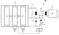
- FIG. 1 shows a schematic circuit diagram of the communications principle, based on inductive coupling, between a base station and an associated transponder station in accordance with one embodiment from the prior art.
- FIG. 2 shows a schematic circuit diagram of the communications principle, based on inductive coupling, between a base station and an associated transponder station in accordance with a first embodiment of the present invention.
- FIG. 3 shows a schematic circuit diagram of the communications principle, based on inductive coupling, between a base station and an associated transponder station in accordance with a second embodiment of the present invention.
- FIGS. 1 to 3 Embodiments, elements or features that are identical or similar are provided with identical reference numbers in FIGS. 1 to 3 .
- an electronic communications system 100 equipped inter alia with a transponder system ( ⁇ transponder station 40 ) that is in turn part of a security system in the form of an electronic immobilizer system for a motor vehicle, is realized by the present invention.
- the transponder station itself, 40 can be carried by the authorized user of the motor vehicle; to this end, the transponder station 40 may be accommodated in, for example, the web of the key belonging to the vehicle's ignition lock.
- the antenna unit 16 supplies the transponder station 40 inductively with power 20 , i.e. the transponder station 40 is fed via an inductive field; on the other, in the active state (see FIGS. 2 and 3 ) of the transponder station 40 , a communication sequence for authentication and identification between the base station 10 and the transponder station 40 takes place, to which end data signals 22 , 24 are exchanged between the base station 10 and the transponder station 40 ; not only can the utilization and/or access entitlement for the motor vehicle be determined by means of these data signals 22 , 24 , but also the base station 10 can be controlled accordingly.
- an up-link frame 22 which, for example, takes the form of at least one LF (Low Frequency) channel with inductive coupling and is transmitted via the signals from the base station 10 to the transponder station 40
- a down-link frame 24 which, for example, takes the form of at least one LF (Low Frequency) channel and is transmitted via the signals from the transponder station 40 to the base station 10 .
- the base station 10 associated functionally and spatially with the motor vehicle starts to generate a signal known as a “Challenge”, which is transmitted via the up-link frame 22 to the transponder station 40 .
- an electronic circuit configuration 42 which is preferably equipped with at least one microprocessor, in the transponder station 40 calculates a signal train known as a “Response”. This response signal is then transmitted from the transponder station 40 via the down-link frame 24 to the base station 10 .
- This data exchange forms a central part of an authentication procedure, which is arbitrary in principle.
- the transponder station 40 Only if, during the authentication or identification, the transponder station 40 is recognized as valid, generally using cryptographic methods, will the engine of the motor vehicle be started in the embodiment example described.
- the method in accordance with the invention uses simple means to undertake a calibration of the LC resonant circuit 13 , 16 .
- a calibration or regulation of the resonant frequency of the LC resonant circuit 13 , 16 is undertaken with the aid of one single, precise reference frequency and by means of a few additional components during the running time of the system.
- the LC resonant circuit 13 , 16 may be tuned to the desired resonant frequency using an additional RC tuning circuit 17 , 18 , equipped with:
- a regulating resistor 18 series-connected to the first element 17 .
- a frequency derived from the clock of the microcontroller 14 may be used as the reference for this purpose.
- the frequency setting may be undertaken automatically via a control circuit.
- the base station 10 equipped with frequency measurement, may be switched, via control commands, into a mode in which the reference frequency is used for activating the LC resonant circuit 13 , 16 ; simultaneously, the actual resonant frequency of the LC resonant circuit 13 , 16 is determined, e.g. by means of phase measurement between the signal at the output terminal of the base unit 30 assigned to the first resistor 11 and the signal at the output terminal of the base unit 30 assigned to the second resistor 15 .
- the value of the variably adjustable resistor 18 is varied. This is continued according to an arbitrary control algorithm, e.g. in accordance with the principle of successive approximation, until the measured resonant frequency corresponds sufficiently accurately with the reference frequency.
- the algorithm described may be repeated as often as desired; as a result, temperature and/or aging effects can also be compensated, which greatly increases the accuracy of the resonant frequency.
Landscapes
- Engineering & Computer Science (AREA)
- Mechanical Engineering (AREA)
- Near-Field Transmission Systems (AREA)
- Radar Systems Or Details Thereof (AREA)
- Selective Calling Equipment (AREA)
- Input Circuits Of Receivers And Coupling Of Receivers And Audio Equipment (AREA)
Abstract
Description
- 100 Electronic communications system
- 10 Base station
- 11 First resistor of the
base unit 30 - 12 Microcontroller unit of the
base unit 30 - 12 a Clock output of the
microcontroller 12 - 13 Capacitive unit of the
base unit 30 - 14 (Analog) interface of the
base unit 30 - 15 Second resistor of the
base unit 30 - 16 Antenna unit of the
base unit 30 - 17 First element in the form of at least one capacitive unit or in the form of at least one inductive unit
- 18 Regulating resistor
- 19 D[igital]/A[analog] converter unit
- 20 Power
- 22 Up-link frame, e.g. in the form of an LF (Low Frequency) channel
- 24 Down-link frame, e.g. in the form of an LF (Low Frequency) channel
- 30 Base unit, in particular a transponder communications device
- 40 Transponder station
- 42 Circuit configuration of the
transponder station 40 - 44 Antenna unit of the
transponder station 40
Claims (12)
Applications Claiming Priority (3)
| Application Number | Priority Date | Filing Date | Title |
|---|---|---|---|
| EP03101190 | 2003-04-29 | ||
| EP03101190.1 | 2003-04-29 | ||
| PCT/IB2004/050470 WO2004096616A1 (en) | 2003-04-29 | 2004-04-20 | Electronic communications system |
Publications (2)
| Publication Number | Publication Date |
|---|---|
| US20070142088A1 US20070142088A1 (en) | 2007-06-21 |
| US7444118B2 true US7444118B2 (en) | 2008-10-28 |
Family
ID=33395960
Family Applications (1)
| Application Number | Title | Priority Date | Filing Date |
|---|---|---|---|
| US10/554,733 Active 2025-10-13 US7444118B2 (en) | 2003-04-29 | 2004-04-20 | Electronic communications system |
Country Status (6)
| Country | Link |
|---|---|
| US (1) | US7444118B2 (en) |
| EP (1) | EP1620293B1 (en) |
| JP (1) | JP2006526329A (en) |
| AT (1) | ATE452054T1 (en) |
| DE (1) | DE602004024669D1 (en) |
| WO (1) | WO2004096616A1 (en) |
Cited By (10)
| Publication number | Priority date | Publication date | Assignee | Title |
|---|---|---|---|---|
| US20070072644A1 (en) * | 2005-09-26 | 2007-03-29 | Igor Golioto | Wireless communication base station with current limiting capability |
| US20090002175A1 (en) * | 2004-10-29 | 2009-01-01 | Hewlett-Packard Development Company, L.P. | Power Transfer for Transponder Devices |
| US8816835B2 (en) | 2010-11-01 | 2014-08-26 | Nxp B.V. | Immobilizer circuit |
| US9143150B1 (en) | 2014-08-25 | 2015-09-22 | Nxp B.V. | Data communications with analog-to-digital conversion |
| US9160519B1 (en) | 2014-08-25 | 2015-10-13 | Nxp B.V. | Communications with synchronization |
| US9374215B2 (en) | 2014-08-25 | 2016-06-21 | Nxp B.V. | Communication synchronization |
| US9485609B2 (en) | 2015-02-06 | 2016-11-01 | Nxp B.V. | Pulse frequency control for wireless communications and ranging |
| US9613475B2 (en) | 2015-05-27 | 2017-04-04 | Nxp B.V. | Communications with interaction detection |
| US9712496B2 (en) | 2015-04-28 | 2017-07-18 | Nxp B.V. | Signal modulation for secure communication |
| US9775034B2 (en) | 2015-02-06 | 2017-09-26 | Nxp B.V. | Communications with distance authentication |
Families Citing this family (7)
| Publication number | Priority date | Publication date | Assignee | Title |
|---|---|---|---|---|
| DE102004037637A1 (en) * | 2004-08-02 | 2006-03-16 | Deutsche Thomson-Brandt Gmbh | Receiver circuit and control method |
| FR2923334A1 (en) * | 2007-11-02 | 2009-05-08 | Johnson Controls Tech Co | Transmitter-receiver circuit for collecting digital code of remote transponder in anti-theft system of motor vehicle, has demodulator electrically connected to measuring point that connects resistors together |
| US20110309689A1 (en) * | 2010-06-17 | 2011-12-22 | Semiconductor Energy Laboratory Co., Ltd. | Electric power transmitting device, electric power receiving device, and power supply method using electric power transmitting and receiving devices |
| CN102523612B (en) * | 2011-12-08 | 2015-01-14 | 电信科学技术研究院 | Spectrum switching method and equipment in cognitive radio system |
| DE102015205040A1 (en) | 2015-03-19 | 2016-09-22 | Continental Automotive Gmbh | Antenna driver circuit, in particular antenna multiplexer for a motor vehicle |
| DE102015205038B4 (en) * | 2015-03-19 | 2019-10-02 | Continental Automotive Gmbh | Reception circuit, in particular for installation in a vehicle access and start system (PASE) |
| US11133845B2 (en) * | 2019-12-05 | 2021-09-28 | Assa Abloy Ab | Detuning detection and compensation for inductive coupling systems |
Citations (8)
| Publication number | Priority date | Publication date | Assignee | Title |
|---|---|---|---|---|
| US5804888A (en) * | 1994-08-26 | 1998-09-08 | Siemens Aktiengesellschaft | Anti-theft system for a motor vehicle |
| US5842118A (en) * | 1996-12-18 | 1998-11-24 | Micron Communications, Inc. | Communication system including diversity antenna queuing |
| EP0901664A1 (en) | 1996-05-24 | 1999-03-17 | Siemens Aktiengesellschaft | Method and device for the contactless transmission of energy or data |
| US20030104848A1 (en) * | 2001-11-30 | 2003-06-05 | Raj Brideglall | RFID device, system and method of operation including a hybrid backscatter-based RFID tag protocol compatible with RFID, bluetooth and/or IEEE 802.11x infrastructure |
| US6650227B1 (en) * | 1999-12-08 | 2003-11-18 | Hid Corporation | Reader for a radio frequency identification system having automatic tuning capability |
| US6731198B1 (en) * | 1999-01-08 | 2004-05-04 | Antaloli Stobbe | Security system, transponder and receiver device |
| US6824054B2 (en) * | 2000-12-20 | 2004-11-30 | Fraunhofer-Gesellschaft Zur Foerderung Der Angewandten Forshcung E.V. | Apparatus and method for simultaneously reading out of passive inductive transponders |
| US20050024198A1 (en) * | 1999-07-20 | 2005-02-03 | Ward William H. | Impedance matching network and multidimensional electromagnetic field coil for a transponder interrogator |
Family Cites Families (2)
| Publication number | Priority date | Publication date | Assignee | Title |
|---|---|---|---|---|
| DE4438287C1 (en) * | 1994-10-26 | 1996-05-09 | Siemens Ag | System for contactless energy and data transmission |
| JPH1159331A (en) * | 1997-08-27 | 1999-03-02 | Denso Corp | Transmitter for keyless entry system and keyless entry system |
-
2004
- 2004-04-20 JP JP2006506864A patent/JP2006526329A/en not_active Withdrawn
- 2004-04-20 US US10/554,733 patent/US7444118B2/en active Active
- 2004-04-20 WO PCT/IB2004/050470 patent/WO2004096616A1/en active Application Filing
- 2004-04-20 AT AT04728387T patent/ATE452054T1/en not_active IP Right Cessation
- 2004-04-20 EP EP04728387A patent/EP1620293B1/en not_active Expired - Lifetime
- 2004-04-20 DE DE602004024669T patent/DE602004024669D1/en not_active Expired - Lifetime
Patent Citations (9)
| Publication number | Priority date | Publication date | Assignee | Title |
|---|---|---|---|---|
| US5804888A (en) * | 1994-08-26 | 1998-09-08 | Siemens Aktiengesellschaft | Anti-theft system for a motor vehicle |
| EP0901664A1 (en) | 1996-05-24 | 1999-03-17 | Siemens Aktiengesellschaft | Method and device for the contactless transmission of energy or data |
| US6703920B2 (en) * | 1996-05-24 | 2004-03-09 | Siemens Aktiengesellschaft | Device and method for contactless transmission of power or data |
| US5842118A (en) * | 1996-12-18 | 1998-11-24 | Micron Communications, Inc. | Communication system including diversity antenna queuing |
| US6731198B1 (en) * | 1999-01-08 | 2004-05-04 | Antaloli Stobbe | Security system, transponder and receiver device |
| US20050024198A1 (en) * | 1999-07-20 | 2005-02-03 | Ward William H. | Impedance matching network and multidimensional electromagnetic field coil for a transponder interrogator |
| US6650227B1 (en) * | 1999-12-08 | 2003-11-18 | Hid Corporation | Reader for a radio frequency identification system having automatic tuning capability |
| US6824054B2 (en) * | 2000-12-20 | 2004-11-30 | Fraunhofer-Gesellschaft Zur Foerderung Der Angewandten Forshcung E.V. | Apparatus and method for simultaneously reading out of passive inductive transponders |
| US20030104848A1 (en) * | 2001-11-30 | 2003-06-05 | Raj Brideglall | RFID device, system and method of operation including a hybrid backscatter-based RFID tag protocol compatible with RFID, bluetooth and/or IEEE 802.11x infrastructure |
Cited By (12)
| Publication number | Priority date | Publication date | Assignee | Title |
|---|---|---|---|---|
| US8536982B2 (en) * | 2004-10-09 | 2013-09-17 | Palm, Inc. | Automatic tuning for RFID systems by changing capacitor values in case of an error |
| US20090002175A1 (en) * | 2004-10-29 | 2009-01-01 | Hewlett-Packard Development Company, L.P. | Power Transfer for Transponder Devices |
| US20070072644A1 (en) * | 2005-09-26 | 2007-03-29 | Igor Golioto | Wireless communication base station with current limiting capability |
| US8700093B2 (en) * | 2005-09-26 | 2014-04-15 | 8631654 Canada Inc. | Wireless communication base station with current limiting capability |
| US8816835B2 (en) | 2010-11-01 | 2014-08-26 | Nxp B.V. | Immobilizer circuit |
| US9143150B1 (en) | 2014-08-25 | 2015-09-22 | Nxp B.V. | Data communications with analog-to-digital conversion |
| US9160519B1 (en) | 2014-08-25 | 2015-10-13 | Nxp B.V. | Communications with synchronization |
| US9374215B2 (en) | 2014-08-25 | 2016-06-21 | Nxp B.V. | Communication synchronization |
| US9485609B2 (en) | 2015-02-06 | 2016-11-01 | Nxp B.V. | Pulse frequency control for wireless communications and ranging |
| US9775034B2 (en) | 2015-02-06 | 2017-09-26 | Nxp B.V. | Communications with distance authentication |
| US9712496B2 (en) | 2015-04-28 | 2017-07-18 | Nxp B.V. | Signal modulation for secure communication |
| US9613475B2 (en) | 2015-05-27 | 2017-04-04 | Nxp B.V. | Communications with interaction detection |
Also Published As
| Publication number | Publication date |
|---|---|
| JP2006526329A (en) | 2006-11-16 |
| WO2004096616A1 (en) | 2004-11-11 |
| EP1620293A1 (en) | 2006-02-01 |
| ATE452054T1 (en) | 2010-01-15 |
| EP1620293B1 (en) | 2009-12-16 |
| US20070142088A1 (en) | 2007-06-21 |
| DE602004024669D1 (en) | 2010-01-28 |
Similar Documents
| Publication | Publication Date | Title |
|---|---|---|
| US7444118B2 (en) | Electronic communications system | |
| US6978126B1 (en) | Transceiver with closed loop control of antenna tuning and power level | |
| US20090261946A1 (en) | Access Control System for a Vehicle | |
| JP2004502177A (en) | Method for measuring the distance between two objects, and for controlling access control to an object or for controlling the use of an object, especially an access control and travel authentication device for a motor vehicle | |
| JP2007532369A (en) | Propagation time measurement system and method of operating the system | |
| US20080211621A1 (en) | Electronic Communication System, in Particular Authentication Control System, as Well as Corresponding Method | |
| KR100387140B1 (en) | Transceiver system | |
| US20060125599A1 (en) | Self-aligning vehicular transmitter system | |
| US5790014A (en) | Charging a transponder in a security system | |
| EP1190405B1 (en) | Transceiver with closed loop control of antenna tuning and power level | |
| US5864302A (en) | Transmitting and receiving system | |
| US8890633B2 (en) | Resonant circuit with automated trimming capabilities | |
| EP3696911B1 (en) | Device to minimize current overshoot in detuned antenna | |
| EP1595201B1 (en) | System and method for calibrating the clock frequency of a clock generator unit over a data line | |
| US20050068157A1 (en) | Arrangement and method for setting a transmit power | |
| US20120086567A1 (en) | Vehicular control system and in-vehicle apparatus | |
| EP0834994A1 (en) | Circuit arrangement comprising an oscillator | |
| EP1298832B1 (en) | Keyless access control receiver | |
| EP0746930B1 (en) | Frequency stabilized fsk transmitter | |
| KR100201567B1 (en) | Transmitter for remote control system of car | |
| US20020027493A1 (en) | Remote signal transmission control including compensation for variations in transmitter components | |
| JP3622675B2 (en) | Portable transmitter | |
| EP1569343A1 (en) | Radio frequency adjustment system | |
| JPH0714787U (en) | Remote control signal transmitter |
Legal Events
| Date | Code | Title | Description |
|---|---|---|---|
| AS | Assignment |
Owner name: KONINKLIJKE PHILIPS ELECTRONICS N.V., NETHERLANDS Free format text: ASSIGNMENT OF ASSIGNORS INTEREST;ASSIGNORS:BOH, FRANK;NOWOTTNICK, JURGEN;REEL/FRAME:018125/0263 Effective date: 20040627 |
|
| AS | Assignment |
Owner name: NXP B.V., NETHERLANDS Free format text: ASSIGNMENT OF ASSIGNORS INTEREST;ASSIGNOR:KONINKLIJKE PHILIPS ELECTRONICS N.V.;REEL/FRAME:019719/0843 Effective date: 20070704 Owner name: NXP B.V.,NETHERLANDS Free format text: ASSIGNMENT OF ASSIGNORS INTEREST;ASSIGNOR:KONINKLIJKE PHILIPS ELECTRONICS N.V.;REEL/FRAME:019719/0843 Effective date: 20070704 |
|
| STCF | Information on status: patent grant |
Free format text: PATENTED CASE |
|
| FPAY | Fee payment |
Year of fee payment: 4 |
|
| AS | Assignment |
Owner name: MORGAN STANLEY SENIOR FUNDING, INC., MARYLAND Free format text: SECURITY AGREEMENT SUPPLEMENT;ASSIGNOR:NXP B.V.;REEL/FRAME:038017/0058 Effective date: 20160218 |
|
| FPAY | Fee payment |
Year of fee payment: 8 |
|
| AS | Assignment |
Owner name: MORGAN STANLEY SENIOR FUNDING, INC., MARYLAND Free format text: CORRECTIVE ASSIGNMENT TO CORRECT THE REMOVE APPLICATION 12092129 PREVIOUSLY RECORDED ON REEL 038017 FRAME 0058. ASSIGNOR(S) HEREBY CONFIRMS THE SECURITY AGREEMENT SUPPLEMENT;ASSIGNOR:NXP B.V.;REEL/FRAME:039361/0212 Effective date: 20160218 |
|
| AS | Assignment |
Owner name: MORGAN STANLEY SENIOR FUNDING, INC., MARYLAND Free format text: CORRECTIVE ASSIGNMENT TO CORRECT THE REMOVE APPLICATION 12681366 PREVIOUSLY RECORDED ON REEL 039361 FRAME 0212. ASSIGNOR(S) HEREBY CONFIRMS THE SECURITY AGREEMENT SUPPLEMENT;ASSIGNOR:NXP B.V.;REEL/FRAME:042762/0145 Effective date: 20160218 Owner name: MORGAN STANLEY SENIOR FUNDING, INC., MARYLAND Free format text: CORRECTIVE ASSIGNMENT TO CORRECT THE REMOVE APPLICATION 12681366 PREVIOUSLY RECORDED ON REEL 038017 FRAME 0058. ASSIGNOR(S) HEREBY CONFIRMS THE SECURITY AGREEMENT SUPPLEMENT;ASSIGNOR:NXP B.V.;REEL/FRAME:042985/0001 Effective date: 20160218 |
|
| AS | Assignment |
Owner name: NXP B.V., NETHERLANDS Free format text: CHANGE OF NAME;ASSIGNOR:PHILIPS SEMICONDUCTORS INTERNATIONAL B.V.;REEL/FRAME:043951/0436 Effective date: 20060929 Owner name: PHILIPS SEMICONDUCTORS INTERNATIONAL B.V., NETHERL Free format text: ASSIGNMENT OF ASSIGNORS INTEREST;ASSIGNOR:KONINKLIJKE PHILIPS ELECTRONICS N.V.;REEL/FRAME:043955/0001 Effective date: 20060928 |
|
| AS | Assignment |
Owner name: NXP B.V., NETHERLANDS Free format text: RELEASE BY SECURED PARTY;ASSIGNOR:MORGAN STANLEY SENIOR FUNDING, INC.;REEL/FRAME:050745/0001 Effective date: 20190903 |
|
| AS | Assignment |
Owner name: MORGAN STANLEY SENIOR FUNDING, INC., MARYLAND Free format text: CORRECTIVE ASSIGNMENT TO CORRECT THE REMOVE APPLICATION 12298143 PREVIOUSLY RECORDED ON REEL 042985 FRAME 0001. ASSIGNOR(S) HEREBY CONFIRMS THE SECURITY AGREEMENT SUPPLEMENT;ASSIGNOR:NXP B.V.;REEL/FRAME:051029/0001 Effective date: 20160218 Owner name: MORGAN STANLEY SENIOR FUNDING, INC., MARYLAND Free format text: CORRECTIVE ASSIGNMENT TO CORRECT THE REMOVE APPLICATION 12298143 PREVIOUSLY RECORDED ON REEL 042762 FRAME 0145. ASSIGNOR(S) HEREBY CONFIRMS THE SECURITY AGREEMENT SUPPLEMENT;ASSIGNOR:NXP B.V.;REEL/FRAME:051145/0184 Effective date: 20160218 Owner name: MORGAN STANLEY SENIOR FUNDING, INC., MARYLAND Free format text: CORRECTIVE ASSIGNMENT TO CORRECT THE REMOVE APPLICATION 12298143 PREVIOUSLY RECORDED ON REEL 039361 FRAME 0212. ASSIGNOR(S) HEREBY CONFIRMS THE SECURITY AGREEMENT SUPPLEMENT;ASSIGNOR:NXP B.V.;REEL/FRAME:051029/0387 Effective date: 20160218 Owner name: MORGAN STANLEY SENIOR FUNDING, INC., MARYLAND Free format text: CORRECTIVE ASSIGNMENT TO CORRECT THE REMOVE APPLICATION 12298143 PREVIOUSLY RECORDED ON REEL 038017 FRAME 0058. ASSIGNOR(S) HEREBY CONFIRMS THE SECURITY AGREEMENT SUPPLEMENT;ASSIGNOR:NXP B.V.;REEL/FRAME:051030/0001 Effective date: 20160218 Owner name: MORGAN STANLEY SENIOR FUNDING, INC., MARYLAND Free format text: CORRECTIVE ASSIGNMENT TO CORRECT THE REMOVE APPLICATION12298143 PREVIOUSLY RECORDED ON REEL 039361 FRAME 0212. ASSIGNOR(S) HEREBY CONFIRMS THE SECURITY AGREEMENT SUPPLEMENT;ASSIGNOR:NXP B.V.;REEL/FRAME:051029/0387 Effective date: 20160218 Owner name: MORGAN STANLEY SENIOR FUNDING, INC., MARYLAND Free format text: CORRECTIVE ASSIGNMENT TO CORRECT THE REMOVE APPLICATION12298143 PREVIOUSLY RECORDED ON REEL 042985 FRAME 0001. ASSIGNOR(S) HEREBY CONFIRMS THE SECURITY AGREEMENT SUPPLEMENT;ASSIGNOR:NXP B.V.;REEL/FRAME:051029/0001 Effective date: 20160218 Owner name: MORGAN STANLEY SENIOR FUNDING, INC., MARYLAND Free format text: CORRECTIVE ASSIGNMENT TO CORRECT THE REMOVE APPLICATION12298143 PREVIOUSLY RECORDED ON REEL 042762 FRAME 0145. ASSIGNOR(S) HEREBY CONFIRMS THE SECURITY AGREEMENT SUPPLEMENT;ASSIGNOR:NXP B.V.;REEL/FRAME:051145/0184 Effective date: 20160218 |
|
| MAFP | Maintenance fee payment |
Free format text: PAYMENT OF MAINTENANCE FEE, 12TH YEAR, LARGE ENTITY (ORIGINAL EVENT CODE: M1553); ENTITY STATUS OF PATENT OWNER: LARGE ENTITY Year of fee payment: 12 |