US7428809B2 - Method for operating an internal combustion engine and a device for carrying out the method - Google Patents
Method for operating an internal combustion engine and a device for carrying out the method Download PDFInfo
- Publication number
- US7428809B2 US7428809B2 US11/236,183 US23618305A US7428809B2 US 7428809 B2 US7428809 B2 US 7428809B2 US 23618305 A US23618305 A US 23618305A US 7428809 B2 US7428809 B2 US 7428809B2
- Authority
- US
- United States
- Prior art keywords
- reagent
- catalytic converter
- internal combustion
- combustion engine
- sensor
- Prior art date
- Legal status (The legal status is an assumption and is not a legal conclusion. Google has not performed a legal analysis and makes no representation as to the accuracy of the status listed.)
- Active, expires
Links
Images

Classifications
-
- F—MECHANICAL ENGINEERING; LIGHTING; HEATING; WEAPONS; BLASTING
- F01—MACHINES OR ENGINES IN GENERAL; ENGINE PLANTS IN GENERAL; STEAM ENGINES
- F01N—GAS-FLOW SILENCERS OR EXHAUST APPARATUS FOR MACHINES OR ENGINES IN GENERAL; GAS-FLOW SILENCERS OR EXHAUST APPARATUS FOR INTERNAL COMBUSTION ENGINES
- F01N3/00—Exhaust or silencing apparatus having means for purifying, rendering innocuous, or otherwise treating exhaust
- F01N3/08—Exhaust or silencing apparatus having means for purifying, rendering innocuous, or otherwise treating exhaust for rendering innocuous
- F01N3/10—Exhaust or silencing apparatus having means for purifying, rendering innocuous, or otherwise treating exhaust for rendering innocuous by thermal or catalytic conversion of noxious components of exhaust
- F01N3/18—Exhaust or silencing apparatus having means for purifying, rendering innocuous, or otherwise treating exhaust for rendering innocuous by thermal or catalytic conversion of noxious components of exhaust characterised by methods of operation; Control
- F01N3/20—Exhaust or silencing apparatus having means for purifying, rendering innocuous, or otherwise treating exhaust for rendering innocuous by thermal or catalytic conversion of noxious components of exhaust characterised by methods of operation; Control specially adapted for catalytic conversion ; Methods of operation or control of catalytic converters
- F01N3/2066—Selective catalytic reduction [SCR]
- F01N3/208—Control of selective catalytic reduction [SCR], e.g. dosing of reducing agent
-
- F—MECHANICAL ENGINEERING; LIGHTING; HEATING; WEAPONS; BLASTING
- F01—MACHINES OR ENGINES IN GENERAL; ENGINE PLANTS IN GENERAL; STEAM ENGINES
- F01N—GAS-FLOW SILENCERS OR EXHAUST APPARATUS FOR MACHINES OR ENGINES IN GENERAL; GAS-FLOW SILENCERS OR EXHAUST APPARATUS FOR INTERNAL COMBUSTION ENGINES
- F01N2560/00—Exhaust systems with means for detecting or measuring exhaust gas components or characteristics
- F01N2560/02—Exhaust systems with means for detecting or measuring exhaust gas components or characteristics the means being an exhaust gas sensor
- F01N2560/026—Exhaust systems with means for detecting or measuring exhaust gas components or characteristics the means being an exhaust gas sensor for measuring or detecting NOx
-
- F—MECHANICAL ENGINEERING; LIGHTING; HEATING; WEAPONS; BLASTING
- F01—MACHINES OR ENGINES IN GENERAL; ENGINE PLANTS IN GENERAL; STEAM ENGINES
- F01N—GAS-FLOW SILENCERS OR EXHAUST APPARATUS FOR MACHINES OR ENGINES IN GENERAL; GAS-FLOW SILENCERS OR EXHAUST APPARATUS FOR INTERNAL COMBUSTION ENGINES
- F01N2560/00—Exhaust systems with means for detecting or measuring exhaust gas components or characteristics
- F01N2560/06—Exhaust systems with means for detecting or measuring exhaust gas components or characteristics the means being a temperature sensor
-
- F—MECHANICAL ENGINEERING; LIGHTING; HEATING; WEAPONS; BLASTING
- F01—MACHINES OR ENGINES IN GENERAL; ENGINE PLANTS IN GENERAL; STEAM ENGINES
- F01N—GAS-FLOW SILENCERS OR EXHAUST APPARATUS FOR MACHINES OR ENGINES IN GENERAL; GAS-FLOW SILENCERS OR EXHAUST APPARATUS FOR INTERNAL COMBUSTION ENGINES
- F01N2610/00—Adding substances to exhaust gases
- F01N2610/02—Adding substances to exhaust gases the substance being ammonia or urea
-
- F—MECHANICAL ENGINEERING; LIGHTING; HEATING; WEAPONS; BLASTING
- F01—MACHINES OR ENGINES IN GENERAL; ENGINE PLANTS IN GENERAL; STEAM ENGINES
- F01N—GAS-FLOW SILENCERS OR EXHAUST APPARATUS FOR MACHINES OR ENGINES IN GENERAL; GAS-FLOW SILENCERS OR EXHAUST APPARATUS FOR INTERNAL COMBUSTION ENGINES
- F01N2610/00—Adding substances to exhaust gases
- F01N2610/14—Arrangements for the supply of substances, e.g. conduits
- F01N2610/1453—Sprayers or atomisers; Arrangement thereof in the exhaust apparatus
- F01N2610/146—Control thereof, e.g. control of injectors or injection valves
-
- F—MECHANICAL ENGINEERING; LIGHTING; HEATING; WEAPONS; BLASTING
- F01—MACHINES OR ENGINES IN GENERAL; ENGINE PLANTS IN GENERAL; STEAM ENGINES
- F01N—GAS-FLOW SILENCERS OR EXHAUST APPARATUS FOR MACHINES OR ENGINES IN GENERAL; GAS-FLOW SILENCERS OR EXHAUST APPARATUS FOR INTERNAL COMBUSTION ENGINES
- F01N2900/00—Details of electrical control or of the monitoring of the exhaust gas treating apparatus
- F01N2900/06—Parameters used for exhaust control or diagnosing
- F01N2900/08—Parameters used for exhaust control or diagnosing said parameters being related to the engine
-
- Y—GENERAL TAGGING OF NEW TECHNOLOGICAL DEVELOPMENTS; GENERAL TAGGING OF CROSS-SECTIONAL TECHNOLOGIES SPANNING OVER SEVERAL SECTIONS OF THE IPC; TECHNICAL SUBJECTS COVERED BY FORMER USPC CROSS-REFERENCE ART COLLECTIONS [XRACs] AND DIGESTS
- Y02—TECHNOLOGIES OR APPLICATIONS FOR MITIGATION OR ADAPTATION AGAINST CLIMATE CHANGE
- Y02T—CLIMATE CHANGE MITIGATION TECHNOLOGIES RELATED TO TRANSPORTATION
- Y02T10/00—Road transport of goods or passengers
- Y02T10/10—Internal combustion engine [ICE] based vehicles
- Y02T10/12—Improving ICE efficiencies
Definitions
- the present invention is directed to a method for operating an internal combustion engine, having at least one catalytic converter, an NOx sensor and a device provided in the exhaust area for carrying out the method.
- German Patent Application No. DE 199 03 439 describes a method and a device for operating an internal combustion engine in whose exhaust area an SCR (selective catalytic reduction) catalytic converter is provided which uses a reagent to reduce nitrogen oxides in the exhaust gas of an internal combustion engine to nitrogen.
- the reagent is preferably metered as a function of performance characteristics of the internal combustion engine such as the speed and the quantity of fuel injected.
- fuel is preferably metered based on operating parameters of the exhaust gas, such as the exhaust gas temperature or the operating temperature of the SCR catalytic converter.
- the reducing agent ammonia which may be obtained from a urea-water solution, is used as the reagent.
- the reagent or precursors of the reagent must be metered carefully. If the amount metered is too low, this results in nitrogen oxides no longer being completely reduced in the SCR catalytic converter. If the metering is too high, this results in leakage of reagent, which may result in unnecessarily high reagent consumption as well as an unpleasant odor problem, depending on the nature of the reagent.
- ammonia is toxic.
- German Patent Application No. DE 197 39 848 describes a procedure using which crude NOx emissions of an internal combustion engine may be calculated at least approximately from known performance characteristics of the engine.
- the starting point is an engine characteristics map, which is based on the speed and torque of the engine.
- corrections may also be provided, e.g., as a function of the lambda value.
- German Patent Application No. DE 10 2004 031 624 (not a prior publication) describes a method for operating an SCR catalytic converter used for purifying the exhaust gas of an internal combustion engine; with this method, control or regulation of the reagent filling level in the SCR catalytic converter is provided at a predefined setpoint storage volume.
- the targeted specification of the setpoint storage volume ensures that an adequate quantity of reagent for the most thorough possible elimination of crude NOx emissions produced by the internal combustion engine is available in non-steady states of the engine while avoiding reagent leakage.
- the reagent filling level of the SCR catalytic converter is determined on the basis of a catalytic converter model that takes into account the NOx mass flow entering the SCR catalytic converter, the NOx mass flow leaving the SCR catalytic converter, the catalytic converter temperature and, if necessary, the reagent leakage.
- the maximum possible reagent filling level of the SCR catalytic converter depends in particular on the operating temperature of the SCR catalytic converter.
- the maximum possible reagent filling level is highest at low operating temperatures and drops toward lower values with increasing operating temperatures.
- the efficiency of the SCR catalytic converter depends on the catalytic activity, which is also low at low operating temperatures, passing through a maximum with an increase in operating temperature and then dropping again with a further increase in operating temperature.
- German Patent No. DE 199 60 731 describes an NOx sensor which detects the NOx concentration in an exhaust gas stream of an internal combustion engine.
- the circuit system provided for operating the NOx sensor permits an adjustment of the potentials with a very small offset relative to one another.
- German Patent No. DE 199 62 912 also describes an NOx sensor for detecting the NOx concentration in an exhaust gas stream.
- a circuit system changes the voltages supplied as a function of the currents flowing in the electrode leads or the currents flowing between the electrodes in such a way that the voltages applied to the electrodes inside the sensor have the predefined setpoints.
- the NOx sensors described here have multiple chambers interconnected through the diffusion barriers.
- the O 2 concentration is reduced to a predetermined value in the first chamber by a first electrolytic oxygen pumping cell.
- Conditions in the first chamber such as temperature, catalytic effect of the electrode material and pumping voltage are selected to prevent decomposition of the NOx into N 2 and O 2 .
- O 2 is also pumped out.
- O 2 is again pumped out at a second pump electrode down to a very low O 2 concentration. This promotes an NOx reduction reaction.
- Electrochemical reduction then takes place at a third pumping electrode. The intensity of the pumping current across the third electrode in the second chamber may thus be used as a measure of the NOx concentration in the exhaust gas.
- a third chamber is connected to ambient air and contains an air reference electrode.
- Known amperometric dual-chamber NOx sensors have a cross-sensitivity to ammonia (NH 3 ) due to the measurement principle.
- Ammonia present in the exhaust gas results in distortion of the sensor signal due to the reaction 4NH 3 +5O 2 ⁇ 4NO+6H 2 O.
- An object of the present invention is to provide a method for operating an internal combustion engine in whose exhaust area at least one catalytic converter and an NOx sensor are provided and a device for carrying out the method using which the least possible reagent leakage of a reagent required in the catalytic converter occurs.
- the method according to the present invention is directed to at least one catalytic converter situated in the exhaust area of the internal combustion engine and at least one NOx sensor situated downstream from the catalytic converter.
- the NOx sensor has a cross-sensitivity to a reagent which is required in the catalytic converter.
- a selection signal is made available in predefined operating states of the internal combustion engine. When this signal occurs, the sensor signal provided by the NOx sensor is interpreted at least as a measure of the reagent concentration which exists downstream from the catalytic converter and referred to below as reagent leakage.
- the method according to the present invention makes it possible to make use of the cross-sensitivity of an NOx sensor, which is undesirable per se.
- the choice of predefined operating states of the internal combustion engine is preferably made from the standpoint that the engine has little or no crude NOx emissions in those states so that the sensor signal supplied by the NOx sensor occurs at least approximately only because of the cross-sensitivity and thus reflects at least approximately a measure of reagent leakage.
- idling is provided as a predefined operating state of the internal combustion engine. Idling is preferably detected by the fact that the engine speed is in a predefinable rpm range and the quantity of fuel supplied to the engine is below a predefined fuel quantity threshold value or is within a predefined range.
- overrun is provided as a predefined operating state of the internal combustion engine. Overrun is preferably detected by the fact that the speed of the internal combustion engine is above a predefined rpm threshold value and the engine is not receiving any fuel.
- the internal combustion engine speed and a fuel signal are available anyway so that no additional sensors are necessary.
- the catalytic converter is preferably designed as an SCR catalytic converter which converts the crude NOx emissions of the internal combustion engine into less harmful compounds using a reagent.
- Ammonia is an example of the reagent provided.
- the reagent may either be introduced directly into the exhaust track upstream from the catalytic converter or supplied internally within the engine. When ammonia is provided as the reagent, for example, it may be obtained from a starting material such as a urea-water solution or ammonium carbamate.
- the device according to the present invention for carrying out the method relates to a control unit equipped for carrying out the method.
- the control unit contains in particular an operating state detection means which provides the selection signal when predefined operating states of the engine occur. When this signal occurs, the sensor signal detected by the NOx sensor is analyzed at least as a measure of reagent leakage.
- the control unit preferably has an electric memory in which the method steps are stored as a computer program.
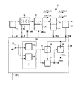
- the FIGURE shows a technical environment in which a method according to the present invention is carried out.
- the Figure shows an internal combustion engine 10 having an air sensor 11 in its intake area and a reagent introducing device 21 , a catalytic converter 22 and an NOx sensor 23 in its exhaust area 20 .
- Air sensor 11 supplies a control unit 30 with an air signal ml
- internal combustion engine 10 supplies a speed N
- a temperature sensor 31 provided for catalytic converter 22 supplies a catalytic converter temperature TKat
- NOx sensor 23 supplies a sensor signal ShK
- an accelerator pedal (not shown) of a motor vehicle (also not shown) supplies a torque setpoint MFa.
- Control unit 30 delivers a fuel signal mK to a fuel metering device 40 provided for internal combustion engine 10 and a reagent signal mRea to a metering valve 41 provided for reagent introducing device 21 .
- Control unit 30 contains an operating state detection means 50 which receives speed N and fuel signal mK.
- Operating state detection means 50 which includes an overrun detection means 52 and an idling detection means 53 , supplies a selection signal 51 .
- Selection signal 51 is delivered to a switch 60 and to a memory 61 .
- Switch 60 connects sensor signal ShK to memory 61 which supplies reagent leakage signal SRea that is supplied to an adder 62 .
- Adder 62 subtracts reagent leakage signal SRea from sensor signal ShK and supplies an NOx signal SNOx.
- Control unit 30 determines fuel signal mK as a function of torque setpoint MFa and preferably also as a function of air signal ml and/or speed N.
- Torque setpoint MFa corresponds essentially to the intent of a driver of a motor vehicle (not shown) in which internal combustion engine 10 is used as a drive.
- Catalytic converter 22 is preferably designed as an SCR catalytic converter which supports reaction of NOx with a reagent which is introduced into exhaust area 20 using reagent introducing device 21 or, if necessary, is made available internally within the engine.
- catalytic converter 22 other catalytic converters (not shown) and/or a particle filter may be provided in exhaust area 20 .
- a precursor may be provided.
- a urea-water solution or ammonium carbamate may be provided as the precursor.
- the quantity of reagent and/or the reagent stream is set by metering valve 41 which is connected to a supply container (not shown).
- Control unit 30 defines the opening cross section of metering valve 41 , using metering signal mRea, for example.
- the metering of the reagent with metering signal mRead is determined, for example, on the basis of crude NOx emissions dmNOxvK of internal combustion engine 10 and is optionally defined as a function of the temperature of SCR catalytic converter 22 .
- Crude NOx emissions dmNOxvK of internal combustion engine 10 depend on the operating point of engine 10 , which is determined at least by the torque of engine 10 , which corresponds mostly to fuel signal mK.
- Speed N is preferably also taken into account here.
- Including catalytic converter temperature TKat takes into account the temperature-dependent reagent storage capacity of SCR catalytic converter 22 .
- Temperature sensor 31 provided for determining the temperature, may be situated upstream from SCR catalytic converter 22 , directly on SCR catalytic converter 22 , or downstream from SCR catalytic converter 22 . It is important here that the signal supplied by temperature sensor 31 must at least reflect a measure of catalytic converter temperature TKat. Instead of a temperature measurement, an estimate of catalytic converter temperature TKat may also be provided.
- reagent stream dmReavK upstream from SCR catalytic converter 22 and the operating conditions of SCR catalytic converter 22 NOx concentration dmNOxhK and reagent leakage dmReahK downstream from SCR catalytic converter 22 may occur. Both exhaust components are undesirable. Overmetering of reagent minimizes NOx concentration dmNOxhK. Depending on the reagent storage capacity currently available at the given operating point of SCR catalytic converter 22 , reagent leakage dmReahK cannot be ruled out completely. Metering of reagent is optimizable on the basis of a measurement of reagent leakage dmReahK.
- Reagent leakage dmReahK is detectable in principle by using a special reagent sensor. To minimize the cost of mass production, an additional sensor is not desirable.
- the procedure according to the present invention makes use of the fact that the NOx sensors described in the related art cited above have a cross-sensitivity with respect to the reagent. The cause of this cross-sensitivity has already been described above. Cross-sensitivity is further supported by operating NOx sensor 23 at elevated temperatures by heating the catalytically active surface of the noble metal electrodes.
- NOx sensor 23 Conversion of ammonia with oxygen to nitrogen monoxide and water results in elevated NOx content in NOx sensor 23 , so that sensor signal ShK of NOx sensor 23 reflects the sum of NOx concentration dmNOxhK and reagent leakage dmReahK.
- the procedure according to the present invention involves determining the operating states of internal combustion engine 10 in which engine 10 has the lowest possible crude NOx emissions dmNOxvK.
- sensor signal ShK largely reflects reagent leakage dmReahK by eliminating the NOx concentration dmNOxhK.
- operating state detection means 50 is provided, making available speed N and fuel signal mK, for example. Suitable operating states in which little or no NOx emissions dmNOxvK occur include idling of engine 10 and overrun in particular.
- overrun detection means 52 To detect overrun, overrun detection means 52 is provided, detecting overrun of engine 10 by the fact that speed N exceeds a predefined lower rpm limit and fuel signal mK is zero.
- idling detection means 53 To detect idling of engine 10 , idling detection means 53 is provided, detecting idling, e.g., by the fact that speed N is within a predefined range and fuel signal mK is below a predefined fuel signal threshold. It is also possible to check on whether fuel signal mK is within a predefined range.
- operating state detection means 50 If operating state detection means 50 has detected a selected operating state of internal combustion engine 10 , then operating state detection means 50 supplies selection signal 51 which signals that sensor signal ShK of NOx sensor 23 is at least approximately only reflecting reagent leakage dmReahK.
- Selection signal 51 is made available to switch 60 which supplies sensor signal ShK at its output and relays it to memory 61 .
- Memory 61 is preferably provided to store sensor signal ShK, reflecting reagent leakage dmReahK, at least until again reaching a suitable operating state in which the stored value may be updated.
- memory 61 supplies reagent leakage signal SRea which has already occurred at the output of switch 60 if selection signal 51 has closed switch 60 .
- Reagent leakage signal SRea may be used to set metering signal mRea.
- Reagent leakage signal SRea may also be used for at least approximate determination of NOx concentration dmNOxhK downstream from SCR catalytic converter 22 . If the operating conditions of the internal combustion engine are outside the suitable conditions, sensor signal ShK will reflect the sum of NOx concentration dmNOxhK and reagent leakage dmReahK. By forming a difference in adder 62 , which subtracts reagent leakage signal SRea from sensor signal ShK, NOx signal SNOx is obtained which at least approximately reflects NOx concentration dmNOxhK during the entire operation of internal combustion engine 10 .
- NOx signal SNOx may also be used to define metering signal mRea, e.g., as part of a regulation of the reagent filling level in SCR catalytic converter 22 , as described in greater detail in the related art cited above.
Abstract
Description
Claims (8)
Applications Claiming Priority (2)
| Application Number | Priority Date | Filing Date | Title |
|---|---|---|---|
| DE102004046639.4 | 2004-09-25 | ||
| DE102004046639A DE102004046639A1 (en) | 2004-09-25 | 2004-09-25 | Method for operating an internal combustion engine and device for carrying out the method |
Publications (2)
| Publication Number | Publication Date |
|---|---|
| US20060080952A1 US20060080952A1 (en) | 2006-04-20 |
| US7428809B2 true US7428809B2 (en) | 2008-09-30 |
Family
ID=35219470
Family Applications (1)
| Application Number | Title | Priority Date | Filing Date |
|---|---|---|---|
| US11/236,183 Active 2026-08-10 US7428809B2 (en) | 2004-09-25 | 2005-09-26 | Method for operating an internal combustion engine and a device for carrying out the method |
Country Status (4)
| Country | Link |
|---|---|
| US (1) | US7428809B2 (en) |
| EP (1) | EP1640578B1 (en) |
| JP (1) | JP4663461B2 (en) |
| DE (2) | DE102004046639A1 (en) |
Cited By (8)
| Publication number | Priority date | Publication date | Assignee | Title |
|---|---|---|---|---|
| US20100257842A1 (en) * | 2007-09-19 | 2010-10-14 | Peter Bauer | Method for detecting the minimum opening time of a reducing agent feed device in an exhaust gas aftertreatment system comprising an scr catalyst |
| US20110005202A1 (en) * | 2009-07-10 | 2011-01-13 | Gm Global Technology Operations, Inc. | Identifying ammonia slip conditions in a selective catalytic reduction application |
| US20110131956A1 (en) * | 2009-12-09 | 2011-06-09 | Honda Motor Co., Ltd. | Catalyst degradation determination device for exhaust purification system |
| US20110146239A1 (en) * | 2009-12-21 | 2011-06-23 | Robert Bosch Gmbh | Method for monitoring a pollutant conversion capacity in an exhaust gas aftertreatment system |
| US20110239629A1 (en) * | 2008-12-08 | 2011-10-06 | Mitsubishi Heavy Industries, Ltd. | Flue gas purifying device |
| US8561387B2 (en) | 2008-09-18 | 2013-10-22 | Continental Automotive Gmbh | Method for checking the seal of a reagent injector |
| US8834821B2 (en) | 2011-05-03 | 2014-09-16 | Cummins Inc. | Control techniques for an SCR aftertreatment system |
| FR3076573A1 (en) * | 2018-01-10 | 2019-07-12 | Psa Automobiles Sa | METHOD FOR IDENTIFYING THE RELEASE NATURE OF A SELECTIVE CATALYTIC REDUCTION SYSTEM IN AN EXHAUST LINE |
Families Citing this family (4)
| Publication number | Priority date | Publication date | Assignee | Title |
|---|---|---|---|---|
| DE102008041603A1 (en) * | 2008-08-27 | 2010-03-04 | Robert Bosch Gmbh | Method for operating an internal combustion engine with SCR catalytic converter |
| DE102008056791A1 (en) | 2008-11-11 | 2010-05-12 | Volkswagen Ag | Sensor device for measuring an ammonia concentration |
| DE102008059773A1 (en) | 2008-12-01 | 2010-06-02 | Volkswagen Ag | Method for operating an SCR catalyst device |
| EP2388450B1 (en) * | 2009-01-13 | 2016-08-03 | Toyota Jidosha Kabushiki Kaisha | Exhaust gas purification device for internal combustion engines |
Citations (21)
| Publication number | Priority date | Publication date | Assignee | Title |
|---|---|---|---|---|
| US4751054A (en) * | 1985-07-16 | 1988-06-14 | Babcock - Hitachi Kabushiki Kaisha | Apparatus for removing NOx from a gas |
| US5369956A (en) * | 1992-05-27 | 1994-12-06 | Mercedes-Benz Ag | Exhaust gas aftertreatment device for internal combustion engines |
| US5540047A (en) * | 1993-10-06 | 1996-07-30 | Siemens Aktiengesellschaft | Method for reducing the nitrogen oxide concentration in the exhaust of an internal combustion engine or of a firing system |
| EP0820799A2 (en) | 1996-07-25 | 1998-01-28 | Ngk Insulators, Ltd. | System for and method of removing NOx from exhaust gases |
| DE19739848A1 (en) | 1997-09-11 | 1999-03-18 | Bosch Gmbh Robert | Internal combustion engine, in particular for a motor vehicle |
| WO1999043420A1 (en) | 1998-02-27 | 1999-09-02 | Volkswagen Aktiengesellschaft | CONTROL OF AN NOx-ABSORBING CATALYTIC CONVERTER |
| DE19903439A1 (en) | 1999-01-29 | 2000-08-03 | Bosch Gmbh Robert | Method and device for controlling an exhaust gas aftertreatment system |
| US6119448A (en) * | 1997-08-21 | 2000-09-19 | Man Nutzfahrzeuge Ag | Method for metering a reducing agent into NOx -containing exhaust gas of an internal combustion engine |
| US6247303B1 (en) * | 1997-05-16 | 2001-06-19 | Siemens Aktiengesellschaft | Method and device for removing oxidic noxious substances in an oxygen-containing exhaust gas and engine which is operated therewith |
| DE19960731A1 (en) | 1999-12-16 | 2001-06-28 | Bosch Gmbh Robert | Circuit arrangement for operating an exhaust gas probe |
| DE19962912A1 (en) | 1999-12-23 | 2001-07-05 | Bosch Gmbh Robert | Method for operating a sensor for determining the concentration of oxidizing gases in gas mixtures |
| US6295809B1 (en) * | 1999-07-12 | 2001-10-02 | Ford Global Technologies, Inc. | Emission control system with a catalyst |
| US6305160B1 (en) * | 1999-07-12 | 2001-10-23 | Ford Global Technologies, Inc. | Emission control system |
| US6546720B2 (en) * | 2001-09-04 | 2003-04-15 | Ford Global Technologies, Inc. | Method and apparatus for controlling the amount of reactant to be added to a substance using a sensor which is responsive to both the reactant and the substance |
| US20030216855A1 (en) | 2002-05-15 | 2003-11-20 | Liang Cho Y. | NOx emission-control system using a virtual sensor |
| US20040098974A1 (en) | 2002-11-21 | 2004-05-27 | Nieuwstadt Michiel J. Van | Exhaust gas aftertreatment systems |
| US6981368B2 (en) * | 2002-11-21 | 2006-01-03 | Ford Global Technologies, Llc | Exhaust gas aftertreatment systems |
| US20060010857A1 (en) * | 2004-07-14 | 2006-01-19 | Eaton Corporation | Hybrid catalyst system for exhaust emissions reduction |
| US6996975B2 (en) * | 2004-06-25 | 2006-02-14 | Eaton Corporation | Multistage reductant injection strategy for slipless, high efficiency selective catalytic reduction |
| US20060096278A1 (en) * | 2004-09-25 | 2006-05-11 | Hartmut Lueders | Method for operating an internal combustion engine and a device for carrying out the method |
| US7067319B2 (en) * | 2004-06-24 | 2006-06-27 | Cummins, Inc. | System for diagnosing reagent solution quality and emissions catalyst degradation |
Family Cites Families (5)
| Publication number | Priority date | Publication date | Assignee | Title |
|---|---|---|---|---|
| JP2001303934A (en) * | 1998-06-23 | 2001-10-31 | Toyota Motor Corp | Exhaust emission control device for internal combustion engine |
| JP2003148198A (en) * | 2001-11-13 | 2003-05-21 | Toyota Motor Corp | Exhaust emission control device of internal combustion engine |
| DE10254843A1 (en) * | 2002-11-25 | 2004-06-03 | Robert Bosch Gmbh | Method of monitoring motor vehicle exhaust gas cleaning system involves injecting urea-water mix into exhaust to determine if sensor output varies |
| DE10300298A1 (en) * | 2003-01-02 | 2004-07-15 | Daimlerchrysler Ag | Exhaust gas aftertreatment device and method |
| DE102004031624A1 (en) | 2004-06-30 | 2006-02-02 | Robert Bosch Gmbh | Method for operating a catalyst used for cleaning the exhaust gas of an internal combustion engine and apparatus for carrying out the method |
-
2004
- 2004-09-25 DE DE102004046639A patent/DE102004046639A1/en not_active Withdrawn
-
2005
- 2005-07-26 EP EP05106878A patent/EP1640578B1/en not_active Expired - Fee Related
- 2005-07-26 DE DE502005001868T patent/DE502005001868D1/en active Active
- 2005-09-15 JP JP2005267986A patent/JP4663461B2/en not_active Expired - Fee Related
- 2005-09-26 US US11/236,183 patent/US7428809B2/en active Active
Patent Citations (23)
| Publication number | Priority date | Publication date | Assignee | Title |
|---|---|---|---|---|
| US4751054A (en) * | 1985-07-16 | 1988-06-14 | Babcock - Hitachi Kabushiki Kaisha | Apparatus for removing NOx from a gas |
| US5369956A (en) * | 1992-05-27 | 1994-12-06 | Mercedes-Benz Ag | Exhaust gas aftertreatment device for internal combustion engines |
| US5540047A (en) * | 1993-10-06 | 1996-07-30 | Siemens Aktiengesellschaft | Method for reducing the nitrogen oxide concentration in the exhaust of an internal combustion engine or of a firing system |
| EP0820799A2 (en) | 1996-07-25 | 1998-01-28 | Ngk Insulators, Ltd. | System for and method of removing NOx from exhaust gases |
| US6247303B1 (en) * | 1997-05-16 | 2001-06-19 | Siemens Aktiengesellschaft | Method and device for removing oxidic noxious substances in an oxygen-containing exhaust gas and engine which is operated therewith |
| US6119448A (en) * | 1997-08-21 | 2000-09-19 | Man Nutzfahrzeuge Ag | Method for metering a reducing agent into NOx -containing exhaust gas of an internal combustion engine |
| DE19739848A1 (en) | 1997-09-11 | 1999-03-18 | Bosch Gmbh Robert | Internal combustion engine, in particular for a motor vehicle |
| WO1999043420A1 (en) | 1998-02-27 | 1999-09-02 | Volkswagen Aktiengesellschaft | CONTROL OF AN NOx-ABSORBING CATALYTIC CONVERTER |
| DE19903439A1 (en) | 1999-01-29 | 2000-08-03 | Bosch Gmbh Robert | Method and device for controlling an exhaust gas aftertreatment system |
| US6532736B2 (en) * | 1999-07-12 | 2003-03-18 | Ford Global Technologies, Inc. | Emission control system with a catalyst |
| US6295809B1 (en) * | 1999-07-12 | 2001-10-02 | Ford Global Technologies, Inc. | Emission control system with a catalyst |
| US6305160B1 (en) * | 1999-07-12 | 2001-10-23 | Ford Global Technologies, Inc. | Emission control system |
| DE19960731A1 (en) | 1999-12-16 | 2001-06-28 | Bosch Gmbh Robert | Circuit arrangement for operating an exhaust gas probe |
| DE19962912A1 (en) | 1999-12-23 | 2001-07-05 | Bosch Gmbh Robert | Method for operating a sensor for determining the concentration of oxidizing gases in gas mixtures |
| US6546720B2 (en) * | 2001-09-04 | 2003-04-15 | Ford Global Technologies, Inc. | Method and apparatus for controlling the amount of reactant to be added to a substance using a sensor which is responsive to both the reactant and the substance |
| US20030216855A1 (en) | 2002-05-15 | 2003-11-20 | Liang Cho Y. | NOx emission-control system using a virtual sensor |
| US6882929B2 (en) * | 2002-05-15 | 2005-04-19 | Caterpillar Inc | NOx emission-control system using a virtual sensor |
| US20040098974A1 (en) | 2002-11-21 | 2004-05-27 | Nieuwstadt Michiel J. Van | Exhaust gas aftertreatment systems |
| US6981368B2 (en) * | 2002-11-21 | 2006-01-03 | Ford Global Technologies, Llc | Exhaust gas aftertreatment systems |
| US7067319B2 (en) * | 2004-06-24 | 2006-06-27 | Cummins, Inc. | System for diagnosing reagent solution quality and emissions catalyst degradation |
| US6996975B2 (en) * | 2004-06-25 | 2006-02-14 | Eaton Corporation | Multistage reductant injection strategy for slipless, high efficiency selective catalytic reduction |
| US20060010857A1 (en) * | 2004-07-14 | 2006-01-19 | Eaton Corporation | Hybrid catalyst system for exhaust emissions reduction |
| US20060096278A1 (en) * | 2004-09-25 | 2006-05-11 | Hartmut Lueders | Method for operating an internal combustion engine and a device for carrying out the method |
Cited By (12)
| Publication number | Priority date | Publication date | Assignee | Title |
|---|---|---|---|---|
| US20100257842A1 (en) * | 2007-09-19 | 2010-10-14 | Peter Bauer | Method for detecting the minimum opening time of a reducing agent feed device in an exhaust gas aftertreatment system comprising an scr catalyst |
| US8555618B2 (en) | 2007-09-19 | 2013-10-15 | Continental Automotive Gmbh | Method for detecting the minimum opening time of a reducing agent feed device in an exhaust gas aftertreatment system comprising an SCR catalyst |
| US8561387B2 (en) | 2008-09-18 | 2013-10-22 | Continental Automotive Gmbh | Method for checking the seal of a reagent injector |
| US20110239629A1 (en) * | 2008-12-08 | 2011-10-06 | Mitsubishi Heavy Industries, Ltd. | Flue gas purifying device |
| US8607547B2 (en) * | 2008-12-08 | 2013-12-17 | Mitsubishi Heavy Industries, Ltd. | Flue gas purifying device |
| US20110005202A1 (en) * | 2009-07-10 | 2011-01-13 | Gm Global Technology Operations, Inc. | Identifying ammonia slip conditions in a selective catalytic reduction application |
| US20110131956A1 (en) * | 2009-12-09 | 2011-06-09 | Honda Motor Co., Ltd. | Catalyst degradation determination device for exhaust purification system |
| US8671660B2 (en) * | 2009-12-09 | 2014-03-18 | Honda Motor Co., Ltd. | Catalyst degradation determination device for exhaust purification system |
| US20110146239A1 (en) * | 2009-12-21 | 2011-06-23 | Robert Bosch Gmbh | Method for monitoring a pollutant conversion capacity in an exhaust gas aftertreatment system |
| US9222395B2 (en) | 2009-12-21 | 2015-12-29 | Robert Bosch Gmbh | Method for monitoring a pollutant conversion capacity in an exhaust gas aftertreatment system |
| US8834821B2 (en) | 2011-05-03 | 2014-09-16 | Cummins Inc. | Control techniques for an SCR aftertreatment system |
| FR3076573A1 (en) * | 2018-01-10 | 2019-07-12 | Psa Automobiles Sa | METHOD FOR IDENTIFYING THE RELEASE NATURE OF A SELECTIVE CATALYTIC REDUCTION SYSTEM IN AN EXHAUST LINE |
Also Published As
| Publication number | Publication date |
|---|---|
| DE102004046639A1 (en) | 2006-03-30 |
| DE502005001868D1 (en) | 2007-12-20 |
| JP4663461B2 (en) | 2011-04-06 |
| EP1640578A1 (en) | 2006-03-29 |
| EP1640578B1 (en) | 2007-11-07 |
| US20060080952A1 (en) | 2006-04-20 |
| JP2006090316A (en) | 2006-04-06 |
Similar Documents
| Publication | Publication Date | Title |
|---|---|---|
| US7428809B2 (en) | Method for operating an internal combustion engine and a device for carrying out the method | |
| US7603846B2 (en) | Method for operating an internal combustion engine and a device for carrying out the method | |
| US8176730B2 (en) | Exhaust gas purification device of internal combustion engine | |
| US8024921B2 (en) | Method for operating an internal combustion engine and device for carrying out the method | |
| US7886527B2 (en) | Reductant injection control strategy | |
| US7028465B2 (en) | Method and device for controlling an exhaust treatment system | |
| US8056404B2 (en) | Output calibration apparatus and output calibration method for NOx sensor | |
| US5628186A (en) | Method and apparatus for controlled introduction of a reducing agent into a nitrogen oxide-containing exhaust gas | |
| US8209966B2 (en) | Exhaust emission control device for internal combustion | |
| US8201397B2 (en) | Exhaust gas purification device of internal combustion engine | |
| EP2933451B1 (en) | Fault diagnosis device for exhaust purification system | |
| EP2348202B1 (en) | Exhaust gas purification device for internal combustion engine | |
| US7475535B2 (en) | Diesel aftertreatment systems | |
| US20070137181A1 (en) | Exhaust gas aftertreatment systems | |
| US20040040289A1 (en) | Exhaust emission control and diagnostics | |
| US8578701B2 (en) | Method for operating an internal combustion engine and device for implementing the method | |
| US20040083721A1 (en) | Diesel aftertreatment systems | |
| US9169761B2 (en) | Urea-water addition control unit | |
| JP5182013B2 (en) | NOx sensor abnormality diagnosis device | |
| US10060318B2 (en) | Method for operating a driving system and corresponding driving system | |
| CN110821622A (en) | Method for monitoring an SCR catalyst | |
| Lack et al. | Upstream NO x estimation | |
| KR20050068639A (en) | Catalyst system for a diesel engine |
Legal Events
| Date | Code | Title | Description |
|---|---|---|---|
| AS | Assignment |
Owner name: ROBERT BOSCH GMBH, GERMANY Free format text: ASSIGNMENT OF ASSIGNORS INTEREST;ASSIGNORS:WICKERT, STEFAN;HANDLER, TORSTEN;SAMUELSEN, DIRK;AND OTHERS;REEL/FRAME:017424/0058;SIGNING DATES FROM 20051216 TO 20051221 |
|
| STCF | Information on status: patent grant |
Free format text: PATENTED CASE |
|
| FPAY | Fee payment |
Year of fee payment: 4 |
|
| FPAY | Fee payment |
Year of fee payment: 8 |
|
| MAFP | Maintenance fee payment |
Free format text: PAYMENT OF MAINTENANCE FEE, 12TH YEAR, LARGE ENTITY (ORIGINAL EVENT CODE: M1553); ENTITY STATUS OF PATENT OWNER: LARGE ENTITY Year of fee payment: 12 |