US7424091B2 - Combined panoramic, CT (computed tomography) and cephalometric photographing apparatus - Google Patents
Combined panoramic, CT (computed tomography) and cephalometric photographing apparatus Download PDFInfo
- Publication number
- US7424091B2 US7424091B2 US11/298,857 US29885705A US7424091B2 US 7424091 B2 US7424091 B2 US 7424091B2 US 29885705 A US29885705 A US 29885705A US 7424091 B2 US7424091 B2 US 7424091B2
- Authority
- US
- United States
- Prior art keywords
- sensor
- panoramic
- cephalometric
- ray
- photographing
- Prior art date
- Legal status (The legal status is an assumption and is not a legal conclusion. Google has not performed a legal analysis and makes no representation as to the accuracy of the status listed.)
- Active, expires
Links
- 238000002591 computed tomography Methods 0.000 title claims abstract description 239
- 210000003128 head Anatomy 0.000 description 8
- 238000003384 imaging method Methods 0.000 description 7
- 230000001105 regulatory effect Effects 0.000 description 7
- 238000000034 method Methods 0.000 description 4
- 238000003325 tomography Methods 0.000 description 3
- 238000003745 diagnosis Methods 0.000 description 2
- 230000000694 effects Effects 0.000 description 2
- 238000013170 computed tomography imaging Methods 0.000 description 1
- 230000001276 controlling effect Effects 0.000 description 1
- 210000002455 dental arch Anatomy 0.000 description 1
- 238000006073 displacement reaction Methods 0.000 description 1
- 210000001061 forehead Anatomy 0.000 description 1
- 230000006870 function Effects 0.000 description 1
- 230000005226 mechanical processes and functions Effects 0.000 description 1
- 238000001356 surgical procedure Methods 0.000 description 1
Images


Classifications
-
- A61B6/51—
-
- A—HUMAN NECESSITIES
- A61—MEDICAL OR VETERINARY SCIENCE; HYGIENE
- A61B—DIAGNOSIS; SURGERY; IDENTIFICATION
- A61B6/00—Apparatus for radiation diagnosis, e.g. combined with radiation therapy equipment
- A61B6/50—Clinical applications
- A61B6/501—Clinical applications involving diagnosis of head, e.g. neuroimaging, craniography
-
- A—HUMAN NECESSITIES
- A61—MEDICAL OR VETERINARY SCIENCE; HYGIENE
- A61B—DIAGNOSIS; SURGERY; IDENTIFICATION
- A61B6/00—Apparatus for radiation diagnosis, e.g. combined with radiation therapy equipment
- A61B6/52—Devices using data or image processing specially adapted for radiation diagnosis
- A61B6/5211—Devices using data or image processing specially adapted for radiation diagnosis involving processing of medical diagnostic data
- A61B6/5229—Devices using data or image processing specially adapted for radiation diagnosis involving processing of medical diagnostic data combining image data of a patient, e.g. combining a functional image with an anatomical image
- A61B6/5247—Devices using data or image processing specially adapted for radiation diagnosis involving processing of medical diagnostic data combining image data of a patient, e.g. combining a functional image with an anatomical image combining images from an ionising-radiation diagnostic technique and a non-ionising radiation diagnostic technique, e.g. X-ray and ultrasound
-
- A—HUMAN NECESSITIES
- A61—MEDICAL OR VETERINARY SCIENCE; HYGIENE
- A61B—DIAGNOSIS; SURGERY; IDENTIFICATION
- A61B6/00—Apparatus for radiation diagnosis, e.g. combined with radiation therapy equipment
- A61B6/58—Testing, adjusting or calibrating apparatus or devices for radiation diagnosis
- A61B6/588—Setting distance between source unit and detector unit
-
- A—HUMAN NECESSITIES
- A61—MEDICAL OR VETERINARY SCIENCE; HYGIENE
- A61B—DIAGNOSIS; SURGERY; IDENTIFICATION
- A61B6/00—Apparatus for radiation diagnosis, e.g. combined with radiation therapy equipment
- A61B6/02—Devices for diagnosis sequentially in different planes; Stereoscopic radiation diagnosis
- A61B6/03—Computerised tomographs
Definitions
- the present invention relates to a combined panoramic, CT (Computed Tomography) and cephalometric photographing apparatus, more particularly, to a combined panoramic, computed tomography and cephalometric photographing apparatus, which can vary a distance between an X-ray source part and an X-ray sensor part arranged on a rotary arm and opposed to each other.
- CT Computer Tomography
- cephalometric photographing apparatus which can vary a distance between an X-ray source part and an X-ray sensor part arranged on a rotary arm and opposed to each other.
- an X-ray CT (Computerized Tomography) imaging apparatus is a photographing apparatus in which an X-ray beam of a predetermined amount is transmitted to a patient's site to be imaged or photographed, the transmitted X-ray amount is measured by an X-ray sensor and the measured data is recorded in a memory, and an X-ray absorbing rate of each point of the captured bodily region of the patient is obtained by a computer and is reconstructed into an image.
- an X-ray panoramic photographing apparatus is an apparatus for conducting tomography while rotating along a locus suitable for the form of a dental arch.
- a cephalometric imaging apparatus is a photographing apparatus which is mainly used for corrective orthodontics or orthognatic surgery, and is to take a photograph of a patient's head.
- the conventional X-ray CT photographing apparatus can obtain only a CT image, and the conventional panoramic photographing apparatus can obtain only a photographic image. Therefore, recently, combined panoramic and computed tomography photographing apparatuses have been proposed.
- U.S. Pat. No. 6,118,842 discloses an X-ray imaging apparatus which can conduct both the CT imaging and the panoramic imaging.
- the apparatus includes: an X-ray source for generating X-rays, an X-ray sensor for detecting X-rays having passed through an object, and supporting means for supporting the X-ray source and the X-ray sensor so that the X-ray source and the X-ray sensor are opposed to each other across an object; and mode switching means for switching between a CT mode and a panorama mode.
- mode switching means for switching between a CT mode and a panorama mode.
- To detect X-rays only one X-ray sensor is used, and the X-ray sensor is an area sensor which is capable to detect a large area.
- the X-ray imaging apparatus can obtain the tomography image by converting the photographic mode into the panoramic mode after obtaining the CT image by selecting the CT mode.
- U.S. Pat. No. 6,829,326 discloses a combined panoramic and cephalometric photographing apparatus. When cephalometric photographing is conducted after panoramic photographing, the apparatus conducts the cephalometric photographing after properly moving a collimator so that a panoramic sensor does not detect X-rays generated from an X-ray source.
- the conventional imaging apparatus conducts the CT photographing and the panoramic photographing using only one sensor, and hence, needs an expensive sensor capable of carrying out the two photographing functions. Additionally, the conventional imaging apparatus has another problem in that it is difficult to obtain the optimum image according to the CT photographing or the panoramic photographing since a distance between the X-ray sensor and the X-ray source is uniform.
- CT Computer Tomography
- cephalometric photographing apparatus which can obtain a CT image, a tomographic image and a cephalometric image by using a CT sensor, a panoramic sensor and a cephalometric sensor mounted in one photographing apparatus, and which can apply the optimum enlargement ratio according to panoramic photographing or CT photographing.
- the present invention provides a combined panoramic, CT (Computed Tomography) and cephalometric photographing apparatus.
- the combined panoramic, CT and cephalometric photographing apparatus includes: a base; a supporting pole standing on the base; an elevation member mounted on the supporting pole in such a way as to elevate and displace in a vertical direction; a panoramic and CT photographing part mounted on the front surface of the elevation member; and a cephalometric photographing part connected to a side of the elevation member, wherein the panoramic and CT photographing part includes: a rotary arm supporting member connected to the front upper portion of the elevation member; a rotary arm supported by the rotary arm supporting member and arranging the X-ray source part for generating X-rays and the X-ray sensor part thereon in such a way that the X-ray source part and the X-ray sensor part are opposed to each other, the X-ray sensor part having a panoramic sensor and/or a CT sensor for detecting X-rays which are generated from the X-
- the combined panoramic, CT and cephalometric photographing apparatus further includes X-ray source part driving means mounted at a location where the rotary arm and the X-ray source part are connected with each other.
- the X-ray sensor part is fixed on the rotary arm, and the X-ray source part is horizontally moved in a direction to get near to the X-ray sensor part or in a direction to get away from the X-ray sensor part without regard to the rotary arm.
- the combined panoramic, CT and cephalometric photographing apparatus further includes X-ray source part driving means mounted at a location where the rotary arm and the X-ray source part are connected with each other, and X-ray sensor part driving means located at a location where the rotary arm and the X-ray sensor part are connected with each other.
- the X-ray sensor part is rotated without regard to the rotary arm, and the X-ray source part is horizontally moved in a direction to get near to the X-ray sensor part or in a direction to get away from the X-ray sensor part without regard to the rotary arm.
- the combined panoramic, CT and cephalometric photographing apparatus further includes X-ray sensor part driving means mounted at a location where the rotary arm and the X-ray sensor part are connected with each other.
- the X-ray sensor part is rotated without regard to the rotary arm, and the X-ray source part is fixed on the rotary arm.
- the combined panoramic and computed tomography photographing apparatus provides an effect to take all of a CT image, a panoramic image and a cephalometric image by mount a CT sensor, a panoramic sensor and a cephalometric sensor on one photographing apparatus. Furthermore, the present invention allows the user to take an image in the optimum enlargement ratio according to whether the panoramic photographing or the CT photographing is conducted, by varying and regulating a distance between the X-ray source part and the X-ray sensor part.
- the present invention uses a dedicated X-ray sensor for panoramic photographing and a dedicated X-ray sensor for CT photographing, thereby reducing costs.
- FIG. 1 is a perspective view of a combined panoramic, computed tomography and cephalometric photographing apparatus according to a first preferred embodiment of the present invention.
- FIGS. 2 to 5 are front views for showing an operation of an X-ray source part of the combined panoramic, computed tomography and cephalometric photographing apparatus according to the first preferred embodiment of the present invention.
- FIG. 6 is a perspective view of a combined panoramic, computed tomography and cephalometric photographing apparatus according to a second preferred embodiment of the present invention.
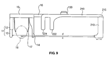
- FIGS. 7 , 8 and 9 are front views for showing an operation of an X-ray source part of the combined panoramic, computed tomography and cephalometric photographing apparatus according to the second preferred embodiment of the present invention.
- FIG. 10 is a perspective view of a combined panoramic, computed tomography and cephalometric photographing apparatus according to a third preferred embodiment of the present invention.
- FIGS. 11 and 12 are front views for showing operations of an X-ray source part and an X-ray sensor part of the combined panoramic, computed tomography and cephalometric photographing apparatus according to the first preferred embodiment of the present invention.
- FIG. 13 is a perspective view of a combined panoramic, computed tomography and cephalometric photographing apparatus according to a fourth preferred embodiment of the present invention.
- FIGS. 14 and 15 are front views for showing an operation of an X-ray source part of the combined panoramic, computed tomography and cephalometric photographing apparatus according to the fourth preferred embodiment of the present invention.
- FIG. 1 is a perspective view of a combined panoramic, CT (Computed Tomography) and cephalometric photographing apparatus according to a first preferred embodiment of the present invention
- FIGS. 2 to 5 are front views for showing an operation of an X-ray source part of the combined panoramic, computed tomography and cephalometric photographing apparatus according to the first preferred embodiment of the present invention.
- the combined panoramic, computed tomography and cephalometric photographing apparatus 100 includes a base 195 , a supporting pole 190 , an elevation member 170 , a panoramic and CT photographing part 100 a , and a cephalometric photographing part 100 b , and can conduct CT photographing, panoramic photographing, and cephalometric photographing.
- the base 195 supports the supporting pole 190 on which the above components are mounted, and the supporting pole 190 stands and is mounted at a side of the base 195 .
- the elevation member 170 is mounted on the supporting pole 190 .
- the elevation member 170 includes a control motor for allowing a vertical displacement. Therefore, the apparatus 100 can regulate its own height according to a patient's height.
- the panoramic and CT photographing part 100 a is mounted on the front surface of the elevation member 170 , and the cephalometric photographing part 100 b is connected to a side of the elevation member 170 .
- the panoramic and CT photographing part 100 a includes: a rotary arm supporting member 150 connected to the front upper portion of the elevation member 170 ; a rotary arm 140 supported by the rotary arm supporting member 150 and arranging the X-ray source part 110 for generating X-rays and the X-ray sensor part 120 thereon in such a way that the X-ray source part 110 and the X-ray sensor part 120 are opposed to each other; and rotary arm driving means 160 interposed between the rotary arm 140 and the rotary arm supporting member 150 for driving the rotary arm 140 .
- a chin supporting member 180 is mounted at the lower portion of the elevation member 170 in nearly orthogonal direction to the elevation member 170 .
- the chin supporting member 180 is formed to position the patient's chin thereon. At this time, the patient's head is located between the X-ray sensor part 120 and the X-ray source part 110 disposed on the rotary arm 140 .
- the chin supporting member 180 can be driven without regard to driving of the elevation member 170 .
- the rotary arm supporting member 150 is mounted at the upper portion of the elevation member 170 in nearly orthogonal direction to the elevation member 170 .
- the rotary arm supporting member 150 supports the rotary arm 140 by the rotary arm driving means 160 .
- the rotary arm supporting member 150 has lines (not shown) formed to allow movement of the rotary arm driving means 160 , so that the rotary arm driving means 160 can move along the lines.
- the rotary arm driving means 160 moves in a direction that the rotary arm supporting member 150 is connected to the elevation member 170 (X-axis movement), and in a horizontal direction which is orthogonal to the X-axis movement direction (X-axis movement). Furthermore, the rotary arm driving means 160 can be rotated on a central axis. That is, the rotary arm driving means 160 conducts the CT photographing or the panoramic photographing by driving the rotary arm 140 .
- the rotary arm driving means 160 rotates the rotary arm 140 on the central axis in order to conduct photographing
- the rotary arm driving means 160 drives the rotary arm 140 on the X-axis and the Y-axis and drives the rotary arm 140 rotationally in order to conduct photographing.
- the rotary arm supporting member 150 and the elevation member 170 respectively includes mechanical components, such as a control motor, therein which are necessary for driving of the rotary arm driving means 160 , and a rotary arm driving means controller for controlling the rotary arm driving means 160 to move the rotary arm 140 along the fixed locus according to the CT photographing or the panoramic photographing.
- the mechanical function will not be described since it is clear to those skilled in the art.
- the X-ray source part 110 is connected to an end of the rotary arm 140 , and the X-ray sensor part 120 is connected to the other end of the rotary arm 140 .
- the X-ray sensor part 120 and the X-ray source part 110 are opposed to each other.
- the X-ray source part 110 emits and irradiates X-rays to a patient 130 or an object.
- the X-ray source part 110 includes an X-ray source and a collimator, so that the emitted X-rays pass through the object and are irradiated to the X-ray sensor part 120 .
- the X-ray source part 110 can be driven without regard to the driving of the rotary arm 140 . That is, X-ray source part driving means 115 is mounted at a part where the rotary arm 140 and the X-ray source part 110 are connected with each other, so that the X-ray source part 110 can be moved. Therefore, the X-ray source part 110 can be horizontally moved in a direction to get near to the X-ray sensor part 120 or in a direction to get away from the X-ray sensor part 120 without regard to the rotary arm 140 .
- the rotary arm 140 includes mechanical components, such as a control motor, therein necessary for driving the X-ray source part 110 .
- the CT photographing or the panoramic photographing can be conducted by varying a distance between the object 130 and the X-ray source part 110 and regulating an enlargement ratio. Referring to FIGS. 2 to 4 , the operation of the present invention will be described in more detail.
- the X-ray sensor part 120 is to convert X-rays into electric signals.
- the X-ray sensor part 120 detects X-rays generated from the X-ray source part 110 , obtains an image, and transmits the obtained image to the outside.
- the X-ray sensor part 120 is fixed on the rotary arm 140 , and includes a sensor mounting part 122 for detaching and attaching a sensor 121 .
- the sensor 121 may be a panoramic sensor or a CT sensor. Therefore, to conduct the CT photographing, a user selects the CT sensor and mounts the CT sensor onto the sensor mounting part 122 manually. To conduct the panoramic photographing, the user separates the CT sensor from the sensor mounting part 122 and mounts the panoramic sensor onto the sensor mounting part 122 manually. That is, in the present invention, the CT sensor for dedicated use of the CT photographing and the panoramic sensor for dedicated use of the panoramic photographing are used according to their use purpose.
- the sensor mounting part 122 may have one of various shapes besides a slot form shown in the drawings.
- Second head fixing means 185 is located between the X-ray source part 110 and the X-ray sensor part 120 .
- the second head fixing means 185 is in the form of a hair band for surrounding the forehead part of the object (patient) 130 , and fixes the head part of the patient. That is, the second head fixing means 185 serves to fix the patient's head part together with the chin supporting member 180 .
- the second head fixing means 185 have an important role in the present invention.
- the second head fixing means 185 is connected to a predetermined portion of the rotary arm supporting member 150 through the rotary arm 140 without being influenced by the driving of the rotary arm 140 .
- a horizontal arm 15 having a cephalometric sensor part 11 , a collimator 18 and first heading fixing means 17 is connected to a side of the elevation member 170 by a connection member 16 .
- the horizontal arm 15 includes the cephalometric sensor part 11 mounted on a side thereof.
- the cephalometric sensor part 11 has a cephalometric sensor mounting part 12 on which a cephalometric sensor is attached and detached, so that the cephalometric sensor 13 is attached and detached manually.
- the cephalometric sensor 13 may be a line scan sensor such as a single line scan sensor or a multi line scan sensor, and in this case, the panoramic sensor 121 may be used as the cephalometric sensor 13 .
- the line scan type sensor needs the collimator 14 for converting X-rays into parallel rays. Therefore, the collimator 14 is mounted on the other side of the horizontal arm 15 in such a way as to be opposed to the cephalometric sensor 13 .
- the cephalometric photographing can be conducted after the panoramic sensor or the CT sensor 121 is separated from the X-ray sensor mounting part. Furthermore, in the case where the X-ray source part 110 , the collimator 14 and the cephalometric sensor part 11 are not arranged in a line, the rotary arm supporting member 150 horizontally moves the X-ray source part 110 in a direction that the rotary arm supporting member 150 is connected to the elevation member 170 , and then the cephalometric photographing can be conducted.
- the first head fixing means 17 is mounted at a predetermined location of the horizontal arm 15 in order to fix the patient's head part (object) 18 .
- the cephalometric sensor 13 may be an area sensor besides the line scan sensor. In this case, the cephalometric sensor 13 does not need the cephalometric sensor mounting part 12 and the collimator 14 . If the area sensor is used as the cephalometric sensor 13 , it is possible to conduct photographing in a one-shot type capable of reducing an exposure rate of X-rays and taking an image of a large area at once. Moreover, the cephalometric sensor 13 can use a film.
- the patient's head part is located on the chin supporting member 180 , and fixed by the head fixing means 185 .
- the X-ray source part 110 and the X-ray sensor part 120 are opposed to each other. At this time, the X-ray sensor part 120 is fixed on the rotary arm 140 . However, the X-ray source part 110 is not fixed on the rotary arm 140 but movable by the X-ray source part driving means 115 .
- the panoramic sensor 121 is mounted on the sensor mounting part 122 disposed on the X-ray sensor part 120 .
- the panoramic sensor 121 may use a line scan sensor such as a single line scan sensor or a multi line scan sensor.
- the user sets a rotation axis of the rotary arm 140 after setting the central axis (x) on a predetermined part of the patient's body, and then, rotates the rotary arm 140 along the circumference of the central axis and along the fixed locus of the rotation axis.
- the enlargement ratio means a ratio of the distance between the object 130 and the X-ray source part 110 to the distance between the X-ray sensor part 120 and the X-ray source part 110 , and the obtained image is enlarged when the enlargement ratio is increased.
- the enlargement ratio is too large, it is harmful to the patient since an amount of the generated X-rays is increased.
- the enlargement ratio is too small, it is difficult to form a mechanical structure. Therefore, it is preferable to conduct photographing after selecting the optimum enlargement ratio in order to make the mechanical structure easy and obtain a good image.
- photographing shall be conducted by properly regulating the enlargement ratio.
- the enlargement ratio is 1:1.1 to 1:1.6.
- the mechanical aspect and an aspect of the highly clear image it is the most preferable to conduct the panoramic photographing after setting the enlargement ratio to 1:1.3.
- the enlargement ratio is about 1:1.3. That is, the user horizontally moves the X-ray source part 110 in the direction to get near to the X-ray sensor part 120 using the X-ray source part driving means 115 , and then, conducts the panoramic photographing.
- the CT photographing is conducted. First, the user separates the panoramic sensor 121 from the sensor mounting part 122 , and then, exchanges the panoramic sensor 121 with the CT sensor 121 .
- the CT sensor may be an area sensor such as a single area sensor or a multi area sensor, or a sensor of a sequentially driving type.
- the CT photographing is conducted by setting the central axis (X) at a predetermined position of the patient and rotating the rotary arm 140 on the central axis.
- the enlargement ratio is 1:1.3 to 1:2. Particularly, it is preferable that the enlargement ratio is 1:1.6 when the patient's anterior teeth part is took by the CT photographing, but 1:1.5 when the patient's posterior teeth part is took by the CT photographing.
- the enlargement ratio is about 1:1.6.
- the enlargement ratio is about 1:1.5.
- the user can conduct the CT photographing after the X-ray source part 110 is horizontally moved in the direction to get away from the X-ray sensor part 120 .
- the cephalometric photographing is conducted.
- the user separates the CT sensor 121 from the sensor mounting part 122 so as not to detect X-rays generated from the X-ray source part 110 and mounts the panoramic sensor, which has been used for the panoramic photographing, on the cephalometric sensor mounting part 12 , and then, conducts the cephalometric photographing.
- the enlargement ratio is nearly 1:1 which means a distance (c) between the object 18 and the X-ray source part 110 to a distance (d) between the cephalometric sensor part 11 and the X-ray source part 110 . If it is necessary to regulate the enlargement ratio at the time of the cephalometric photographing, the X-ray source part 110 is moved and the cephalometric photographing is conducted.
- the X-ray source part 110 is horizontally moved in a direction that the rotary arm supporting member 150 is connected to the elevation member 170 (at right angles to an arrow direction in FIG. 5 ) without regard to driving of the rotary arm 140 , and then, the cephalometric photographing is conducted.
- the combined panoramic, computed tomography and cephalometric photographing apparatus can conduct all of the CT photographing, the panoramic photographing and the cephalometric photographing, and regulate the enlargement ratio by moving the X-ray source part 110 using the X-ray source part driving means 115 .
- FIG. 6 is a perspective view of a combined panoramic, computed tomography and cephalometric photographing apparatus according to a second preferred embodiment of the present invention
- FIGS. 7 and 9 are front views for showing an operation of an X-ray source part of the combined panoramic, computed tomography and cephalometric photographing apparatus according to the second preferred embodiment of the present invention.
- the combined panoramic, computed tomography and cephalometric photographing apparatus 200 includes a base 195 , a supporting pole 190 , an elevation member 170 , a panoramic and CT photographing part 200 a , and a cephalometric photographing part 200 b , and can conduct CT photographing, panoramic photographing, and cephalometric photographing.
- the panoramic and CT photographing part 200 a is mounted on the front surface of the elevation member 170 , and the cephalometric photographing part 200 b is connected to a side of the elevation member 170 .
- the panoramic and CT photographing part 200 a includes: a rotary arm supporting member 150 connected to the front upper portion of the elevation member 170 ; a rotary arm 240 supported by the rotary arm supporting member 150 and arranging the X-ray source part 210 for generating X-rays and the X-ray sensor part 220 thereon in such a way that the X-ray source part 210 and the X-ray sensor part 220 are opposed to each other; and rotary arm driving means 160 interposed between the rotary arm 240 and the rotary arm supporting member 150 for driving the rotary arm 240 .
- the X-ray source part 210 is connected to an end of the rotary arm 240 , and the X-ray sensor part 220 is connected to the other end of the rotary arm 240 .
- the X-ray sensor part 220 and the X-ray source part 210 are opposed to each other.
- the X-ray source part 210 can be driven without regard to the driving of the rotary arm 240 . That is, X-ray source part driving means 215 is mounted at a part where the rotary arm 240 and the X-ray source part 210 are connected with each other, so that the X-ray source part 210 can be moved. Therefore, the X-ray source part 210 can be horizontally moved in a direction to get near to the X-ray sensor part 220 or in a direction to get away from the X-ray sensor part 220 without regard to the rotary arm 240 .
- the X-ray sensor part 220 is fixed on the rotary arm 240 and includes a first sensor mounting part 222 for mounting a panoramic sensor 221 thereon and a second sensor mounting part 224 for mounting a CT sensor 223 thereon.
- the first sensor mounting part 222 is disposed at a portion which is near to the X-ray source part 210
- the second sensor mounting part 224 is disposed at a portion which is away from the X-ray source part 210 in order to regulate the enlargement ratio.
- first and second sensor mounting parts 222 and 224 may select one of various forms besides a slot form shown in the drawings.
- the second preferred embodiment of the present invention includes the X-ray sensor part 220 having all of the panoramic sensor 221 and the CT sensor 223 .
- the panoramic sensor 221 is separated from the first sensor mounting part 222 so as not to detect X-rays generated from the X-ray source part 210 , and then, the CT photographing is conducted.
- the first sensor mounting part 222 on which the panoramic sensor 221 is mounted may slide in a predetermined direction. That is, the first sensor mounting part 222 can slide in the predetermined direction so as not to detect X-rays generated from the X-ray source part 210 .
- the first sensor mounting part 22 may take the slot form for fitting the panoramic sensor thereinto or a form that the panoramic sensor is mounted thereon.
- a horizontal arm 15 having a cephalometric sensor part 11 , a collimator 18 and first heading fixing means 17 is connected to a side of the elevation member 170 by a connection member 16 .
- the horizontal arm 15 includes the cephalometric sensor part 11 mounted on a side thereof.
- the cephalometric sensor part 11 has a cephalometric sensor mounting part 12 on which a cephalometric sensor is attached and detached, so that the cephalometric sensor 13 is attached and detached manually.
- the cephalometric photographing can be conducted after the panoramic sensor 221 and the CT sensor 223 is removed. Furthermore, in the case where the X-ray source part 210 , the collimator 14 and the cephalometric sensor part 11 are not arranged in a line, the X-ray source part 210 is horizontally moved in a direction that the rotary arm supporting member 150 is connected to the elevation member 170 , and then the cephalometric photographing can be conducted.
- the panoramic sensor 221 is mounted on the first sensor mounting part 222 disposed on the X-ray sensor part 220 .
- the user conducts the panoramic photographing after horizontally moving the X-ray source part 210 using the X-ray source part driving means 215 . That is, the X-ray source part 210 is horizontally moved in order to regulate the enlargement ratio properly.
- the user to conduct the CT photographing after the panoramic photographing, the user separates the panoramic sensor 221 form the first sensor mounting part 222 or slides the first sensor mounting part 222 in a predetermined direction. After that, the user conducts the panoramic photographing after horizontally moving the X-ray source part 210 in a proper direction using the X-ray source part driving means 215 .
- the user can conduct the photographing without movement of the X-ray source part 210 .
- the user can conduct the photographing by moving the X-ray source part 210 .
- the cephalometric photographing is conducted.
- the cephalometric sensor 13 is the line scan sensor and the X-ray source part 210 , the collimator 14 and the cephalometric sensor part 11 are arranged in a line
- the user separates the panoramic sensor 221 and the CT sensor 223 from the first and second sensor mounting part 222 and 224 and mounts the panoramic sensor 221 , which has been used for the panoramic photographing, on the cephalometric sensor mounting part 12 , and then, conducts the cephalometric photographing.
- the X-ray source part 210 is horizontally moved in a direction that the rotary arm supporting member 150 is connected to the elevation member 170 (at right angles to an arrow direction in FIG. 9 ) without regard to driving of the rotary arm 240 , and then, the cephalometric photographing is conducted.
- the combined panoramic, computed tomography and cephalometric photographing apparatus can conduct all of the CT photographing, the panoramic photographing and the cephalometric photographing, and regulate the enlargement ratio by moving the X-ray source part 210 using the X-ray source part driving means 215 .
- the second preferred embodiment of the present invention has the same operation as the combined panoramic, CT and cephalometric photographing apparatus according to the first preferred embodiment.
- FIG. 10 is a perspective view of a combined panoramic, computed tomography and cephalometric photographing apparatus according to a third preferred embodiment of the present invention
- FIGS. 11 and 12 are front views for showing operations of an X-ray source part and an X-ray sensor part of the combined panoramic, computed tomography and cephalometric photographing apparatus according to the first preferred embodiment of the present invention.
- the combined panoramic, computed tomography and cephalometric photographing apparatus 300 includes a base 195 , a supporting pole 190 , an elevation member 170 , a panoramic and CT photographing part 300 a , and a cephalometric photographing part 300 b , and can conduct CT photographing, panoramic photographing, and cephalometric photographing.
- the panoramic and CT photographing part 300 a is mounted on the front surface of the elevation member 170 , and the cephalometric photographing part 300 b is connected to a side of the elevation member 170 .
- the panoramic and CT photographing part 300 a includes: a rotary arm supporting member 150 connected to the front upper portion of the elevation member 170 ; a rotary arm 340 supported by the rotary arm supporting member 150 and arranging the X-ray source part 310 for generating X-rays and the X-ray sensor part 320 thereon in such a way that the X-ray source part 310 and the X-ray sensor part 320 are opposed to each other; and rotary arm driving means 160 interposed between the rotary arm 340 and the rotary arm supporting member 150 for driving the rotary arm 340 .
- the X-ray source part 310 is connected to an end of the rotary arm 340 , and the X-ray sensor part 320 is connected to the other end of the rotary arm 340 .
- the X-ray sensor part 320 and the X-ray source part 310 are opposed to each other.
- the X-ray source part 310 can be driven without regard to the driving of the rotary arm 340 . That is, X-ray source part driving means 315 is mounted at a location where the rotary arm 340 and the X-ray source part 310 are connected with each other, so that the X-ray source part 310 can be moved. Therefore, the X-ray source part 310 can be horizontally moved in a direction to get near to the X-ray sensor part 320 or in a direction to get away from the X-ray sensor part 320 without regard to the rotary arm 340 .
- the X-ray sensor part 320 is not fixed on the rotary arm 340 , and rotated without regard to the rotary arm 340 . That is, X-ray sensor part driving means 325 is disposed at a location where the rotary arm 340 and the X-ray sensor part 320 are connected with each other, so that the X-ray sensor part 320 can be rotated.
- the X-ray sensor part 320 includes a first sensor mounting part 322 for mounting a panoramic sensor 321 thereon and a second sensor mounting part 324 for mounting a CT sensor 323 thereon.
- the first sensor mounting part 322 is disposed at a portion which is near to the X-ray source part 310
- the second sensor mounting part 324 is disposed at a portion which is away from the X-ray source part 310 in order to regulate the enlargement ratio.
- the third preferred embodiment of the present invention includes the X-ray sensor part 320 having all of the panoramic sensor 321 and the CT sensor 323 , and can drive both of the X-ray source part 310 and the X-ray sensor part 320 .
- the user rotates the X-ray sensor part 320 to 180° using the X-ray sensor part driving means 325 so that the CT sensor 323 is directly opposed to the X-ray source part 310 , and then conducts the CT photographing.
- a horizontal arm 15 having a cephalometric sensor part 11 , a collimator 18 and first heading fixing means 17 is connected to a side of the elevation member 170 by a connection member 16 .
- the horizontal arm 15 includes the cephalometric sensor part 11 mounted on a side thereof.
- the cephalometric sensor part 11 has a cephalometric sensor mounting part 12 on which a cephalometric sensor is attached and detached, so that the cephalometric sensor 13 is attached and detached manually.
- the cephalometric photographing can be conducted after the panoramic sensor 321 or the CT sensor 323 is removed. Furthermore, in the case where the X-ray source part 310 , the collimator 14 and the cephalometric sensor part 11 are not arranged in a line, the X-ray source part 310 is horizontally moved in a direction that the rotary arm supporting member 150 is connected to the elevation member 170 , and then the cephalometric photographing can be conducted.
- the panoramic sensor 321 is mounted on the first sensor mounting part 322 disposed on the X-ray sensor part 320 .
- the user conducts the panoramic photographing after horizontally moving the X-ray source part 310 using the X-ray source part driving means 315 . That is, the X-ray source part 310 is horizontally moved in order to regulate the enlargement ratio properly.
- the X-ray sensor part 320 is rotated to 180° so that the panoramic sensor 321 gets nearer to the X-ray source part 310 than the CT sensor 323 .
- the X-ray sensor part driving means 325 can rotate the X-ray sensor part 320 on a central axis which is a central point located between the panoramic sensor 321 and the CT sensor 323 .
- a distance (b, b′) between the panoramic sensor 321 or the CT sensor 323 and the X-ray source part 310 is the same.
- the X-ray source part 310 is horizontally moved, the user can conduct the photographing while regulating the enlargement ratio differently since the distance can be regulated.
- the X-ray sensor part 320 is rotated on the central axis which is the central point located between the panoramic sensor 321 and the CT sensor 323 . That is, the X-ray sensor part 320 is rotated in order to locate the CT sensor 323 nearer to the X-ray source part 310 than the panoramic sensor 321 .
- the third preferred embodiment of the present invention has the same operation as the combined panoramic and CT photographing apparatus according to the first preferred embodiment.
- FIG. 13 is a perspective view of a combined panoramic, computed tomography and cephalometric photographing apparatus according to a fourth preferred embodiment of the present invention
- FIGS. 14 and 15 are front views for showing an operation of an X-ray source part of the combined panoramic, computed tomography and cephalometric photographing apparatus according to the fourth preferred embodiment of the present invention.
- the combined panoramic, computed tomography and cephalometric photographing apparatus 400 includes a base 195 , a supporting pole 190 , an elevation member 170 , a panoramic and CT photographing part 400 a , and a cephalometric photographing part 400 b , and can conduct CT photographing, panoramic photographing, and cephalometric photographing.
- the panoramic and CT photographing part 400 a is mounted on the front surface of the elevation member 170 , and the cephalometric photographing part 400 b is connected to a side of the elevation member 170 .
- the panoramic and CT photographing part 400 a includes: a rotary arm supporting member 150 connected to the front upper portion of the elevation member 170 ; a rotary arm 440 supported by the rotary arm supporting member 150 and arranging the X-ray source part 410 for generating X-rays and the X-ray sensor part 420 thereon in such a way that the X-ray source part 410 and the X-ray sensor part 420 are opposed to each other; and rotary arm driving means 160 interposed between the rotary arm 440 and the rotary arm supporting member 150 for driving the rotary arm 440 .
- the X-ray source part 410 is connected to an end of the rotary arm 440 , and the X-ray sensor part 420 is connected to the other end of the rotary arm 440 .
- the X-ray sensor part 420 and the X-ray source part 410 are opposed to each other.
- the X-ray source part 410 is fixed on the rotary arm 440 . Therefore, the X-ray source part 410 is moved together with the rotary arm 440 .
- the X-ray sensor part 420 is not fixed on the rotary arm 440 , and so, can be driven without regard to the driving of the rotary arm 440 . That is, X-ray source part driving means 415 is mounted at a location where the rotary arm 440 and the X-ray sensor part 420 are connected with each other, so that the X-ray sensor part 420 can be moved.
- the X-ray sensor part 420 includes a first sensor mounting part 422 for mounting a panoramic sensor 421 thereon and a second sensor mounting part 424 for mounting a CT sensor 423 thereon.
- the first sensor mounting part 422 is disposed at a portion which is near to the X-ray source part 410
- the second sensor mounting part 424 is disposed at a portion which is away from the X-ray source part 410 in order to regulate the enlargement ratio.
- the fourth preferred embodiment of the present invention suggests the apparatus including the X-ray sensor part 420 having all of the panoramic sensor 421 and the CT sensor 423 , wherein the X-ray source part 410 is fixed on the rotary arm 440 but the X-ray sensor part 420 is movable.
- the user rotates the X-ray sensor part 420 to 180° using the X-ray sensor part driving means 425 so that the CT sensor 423 is directly opposed to the X-ray source part 410 , and then conducts the CT photographing.
- a horizontal arm 15 having a cephalometric sensor part 11 , a collimator 18 and first heading fixing means 17 is connected to a side of the elevation member 170 by a connection member 16 .
- the horizontal arm 15 includes the cephalometric sensor part 11 mounted on a side thereof.
- the cephalometric sensor part 11 has a cephalometric sensor mounting part 12 on which a cephalometric sensor is attached and detached, so that the cephalometric sensor 13 is attached and detached manually.
- the cephalometric photographing can be conducted after the panoramic sensor 421 or the CT sensor 423 is removed.
- the panoramic sensor 421 is mounted on the first sensor mounting part 422 disposed on the X-ray sensor part 420 .
- the X-ray sensor part 420 is rotated to 180° so that the panoramic sensor 421 gets nearer to the X-ray source part 410 than the CT sensor 423 .
- the X-ray source part driving means 415 rotates the X-ray sensor part 420 on an eccentric axis which is located at a predetermined point between the central point between the panoramic sensor 421 and the CT sensor 423 and the CT sensor 423 .
- the enlargement ratio is 1:1.3, but in case of the CT photographing, it is preferable that the enlargement ratio is 1:1.5 or 1:1.6.
- the X-ray sensor part 420 is rotated on the eccentric axis so that the distance (b) between the panoramic sensor 421 and the X-ray sensor part 410 which are opposed to each other is shorter than the distance (b′) between the CT sensor 423 and the X-ray source part 410 which are opposed to each other.
- the X-ray sensor part 420 is rotated on the eccentric shaft which is located at the predetermined point between the central point between the panoramic sensor 421 and the CT sensor 423 and the CT sensor 423 .
- the distance (b′) between the CT sensor 423 and the X-ray source part 410 gets longer than the distance (b) between the panoramic sensor 421 and the X-ray sensor part 410 .
- the distance (a, a′) between the object 130 and the X-ray source part 410 is the same.
- the X-ray sensor part 420 is rotated on the eccentric axis to 180° so that the panoramic sensor 421 gets nearer to the X-ray source part 410 than the CT sensor 423 .
- the fourth preferred embodiment of the present invention has the same operation as the combined panoramic, CT and cephalometric photographing apparatus according to the first preferred embodiment.
- the combined panoramic, CT and cephalometric photographing apparatus is usable in various fields such as a medical treatment, dental treatment, and so on.
- the combined panoramic, CT and cephalometric photographing apparatus can obtain the CT image, the panoramic image and the cephalometric image and conduct all of the panoramic photographing, the CT photographing and the cephalometric photographing respectively using the dedicated X-ray sensors for the panoramic photographing, the CT photographing and the cephalometric photographing.
- the present invention provides the optimum enlargement ratio according to whether the panoramic photographing or the CT photographing is conducted, by regulating the distance between the X-ray source part and the X-ray sensor part, thereby allowing the user to take the image.
Landscapes
- Health & Medical Sciences (AREA)
- Life Sciences & Earth Sciences (AREA)
- Engineering & Computer Science (AREA)
- Medical Informatics (AREA)
- Heart & Thoracic Surgery (AREA)
- Animal Behavior & Ethology (AREA)
- Biophysics (AREA)
- Nuclear Medicine, Radiotherapy & Molecular Imaging (AREA)
- Optics & Photonics (AREA)
- Pathology (AREA)
- Radiology & Medical Imaging (AREA)
- Biomedical Technology (AREA)
- Physics & Mathematics (AREA)
- Molecular Biology (AREA)
- Surgery (AREA)
- High Energy & Nuclear Physics (AREA)
- General Health & Medical Sciences (AREA)
- Public Health (AREA)
- Veterinary Medicine (AREA)
- Computer Vision & Pattern Recognition (AREA)
- Neurology (AREA)
- Neurosurgery (AREA)
- Dentistry (AREA)
- Oral & Maxillofacial Surgery (AREA)
- Apparatus For Radiation Diagnosis (AREA)
Abstract
Description
-
- 100,200,300,400: combined panoramic, CT and cephalometric photographing apparatus
- 100 a,200 a,300 a,400 a: panoramic and CT photographing part
- 100 b,200 b,300 b,400 b: cephalometric photographing part
- 110,210,310,410: X-ray source part
- 120,220,320,420: X-ray sensor part
- 221,321, 421: panoramic sensor
- 223,323,423: CT sensor
- 115,215,315: X-ray source part driving means
- 325: X-ray sensor part driving means
- 140,240,340,440: rotary arm
- 150: rotary arm supporting member
- 160: rotary arm driving means
- 170: elevation member
- 180: chin supporting member
- 11: cephalometric sensor part
- 12: cephalometric sensor mounting part
- 13: cephalometric sensor
- 14: collimator
Claims (25)
Applications Claiming Priority (2)
| Application Number | Priority Date | Filing Date | Title |
|---|---|---|---|
| KR1020050072180A KR100766332B1 (en) | 2005-08-08 | 2005-08-08 | The combined panoramic, computed tomography and cephalometric photographing apparatus |
| KRKR2005-72180 | 2005-08-08 |
Publications (2)
| Publication Number | Publication Date |
|---|---|
| US20070030951A1 US20070030951A1 (en) | 2007-02-08 |
| US7424091B2 true US7424091B2 (en) | 2008-09-09 |
Family
ID=36763595
Family Applications (1)
| Application Number | Title | Priority Date | Filing Date |
|---|---|---|---|
| US11/298,857 Active 2026-01-15 US7424091B2 (en) | 2005-08-08 | 2005-12-09 | Combined panoramic, CT (computed tomography) and cephalometric photographing apparatus |
Country Status (10)
| Country | Link |
|---|---|
| US (1) | US7424091B2 (en) |
| EP (1) | EP1721574B1 (en) |
| JP (1) | JP4480042B2 (en) |
| KR (1) | KR100766332B1 (en) |
| CN (1) | CN100477964C (en) |
| AT (1) | ATE546094T1 (en) |
| DK (1) | DK1721574T3 (en) |
| ES (1) | ES2383111T3 (en) |
| HK (1) | HK1101495A1 (en) |
| WO (1) | WO2007018333A1 (en) |
Cited By (16)
| Publication number | Priority date | Publication date | Assignee | Title |
|---|---|---|---|---|
| US20090052616A1 (en) * | 2005-04-11 | 2009-02-26 | J. Morita Manufacturing Corporation | Unit for X-Ray CT Imaging and X-Ray Imaging Apparatus |
| US20100034340A1 (en) * | 2008-03-13 | 2010-02-11 | Oy Ajat, Ltd. | Single sensor multi-functional dental extra-oral x-ray imaging system and method |
| US20100195786A1 (en) * | 2006-10-10 | 2010-08-05 | Chang Joon Ro | X-ray photographing apparatus |
| US20100278299A1 (en) * | 2007-12-03 | 2010-11-04 | Trophy | Dental x-ray apparatus and associated method |
| WO2010128404A1 (en) | 2009-05-04 | 2010-11-11 | Trophy | Combined panoramic and computed tomography apparatus |
| US8031838B2 (en) | 2009-01-29 | 2011-10-04 | The Invention Science Fund I, Llc | Diagnostic delivery service |
| US8130904B2 (en) | 2009-01-29 | 2012-03-06 | The Invention Science Fund I, Llc | Diagnostic delivery service |
| US20120230467A1 (en) * | 2009-07-30 | 2012-09-13 | Telesystems Co., Ltd. | Radiation imaging apparatus and imaging method using radiation |
| WO2013014488A1 (en) | 2011-07-22 | 2013-01-31 | Trophy | Shield for patient positioning in extra-oral imaging |
| WO2013021231A1 (en) | 2011-08-05 | 2013-02-14 | Trophy | Column height sensing for extra-oral imaging |
| US20130170612A1 (en) * | 2011-12-28 | 2013-07-04 | Cefla Societa Cooperativa | Apparatus and method for acquiring panoramic, teleradiographic and optionally volumetric cbct radiographies |
| US20150374320A1 (en) * | 2014-06-26 | 2015-12-31 | Palodex Group Oy | X-Ray Imaging Unit For Medical Imaging |
| US9265469B2 (en) | 2011-10-05 | 2016-02-23 | Cefla Societa Cooperativa | Device for the acquisition of panoramic radiographies and CBCT volumetric radiographies |
| US20170311910A1 (en) * | 2010-12-22 | 2017-11-02 | Carestream Health, Inc. | Dental imaging with photon-counting detector |
| US20190231284A1 (en) * | 2018-01-26 | 2019-08-01 | Palodex Group Oy | Portable bite part for determining an imaging area of a patient in panoramic, computed tomography, or cephalometric x-ray imaging |
| US20200146650A1 (en) * | 2018-11-09 | 2020-05-14 | Palodex Group Oy | Calibrating an x-ray medical imaging device for cephalometric imaging |
Families Citing this family (19)
| Publication number | Priority date | Publication date | Assignee | Title |
|---|---|---|---|---|
| US7397890B2 (en) * | 2005-04-25 | 2008-07-08 | Xoran Technologies, Inc. | CT system with synthetic view generation |
| US7783002B2 (en) | 2006-09-05 | 2010-08-24 | Palodex Group Oy | Medical x-ray imaging apparatus |
| WO2008035828A1 (en) * | 2006-09-22 | 2008-03-27 | Ray Co., Ltd. | Dental complex imaging system |
| DK2119326T3 (en) | 2007-01-24 | 2017-05-22 | Dental Imaging Tech Corp | Adjustable scanner |
| KR101577475B1 (en) | 2008-02-20 | 2015-12-14 | 이미징 사이언시즈 인터내셔널 엘엘씨 | Adjustable scanner |
| KR101037603B1 (en) * | 2008-07-24 | 2011-05-30 | (주)바텍이우홀딩스 | Dental X-ray Imaging Apparatus using RPR Driving Type |
| CN102413770B (en) * | 2009-06-25 | 2014-06-25 | 株式会社吉田制作所 | X-ray photographing device |
| ITMI20120099A1 (en) * | 2012-01-27 | 2013-07-28 | Gotzen S R L De | APPARATUS AND METHOD FOR DIGITAL RADIOGRAPHY |
| KR101361076B1 (en) * | 2012-03-12 | 2014-02-11 | (주)제노레이 | X-ray Imaging System |
| JP6125200B2 (en) * | 2012-11-05 | 2017-05-10 | 株式会社吉田製作所 | X-ray equipment |
| CN104427279A (en) * | 2013-08-28 | 2015-03-18 | 冠捷投资有限公司 | Multimedia display with camera |
| DK2959835T3 (en) * | 2014-06-26 | 2019-06-24 | Palodex Group Oy | X-ray imaging unit for medical imaging |
| KR101642293B1 (en) | 2014-11-04 | 2016-07-25 | (주)제노레이 | Photographing apparatus of composition-image for dental diagnosis |
| US20170332985A1 (en) * | 2014-12-04 | 2017-11-23 | Trophy | Cephalometric patient positioning unit extra oral dental imaging devices |
| KR20170131696A (en) | 2015-04-29 | 2017-11-29 | (주)바텍이우홀딩스 | X-ray photographing apparatus and method |
| CN104887262B (en) * | 2015-06-29 | 2017-10-20 | 青岛大学附属医院 | Digitalized learning course machine |
| KR101725642B1 (en) * | 2015-07-17 | 2017-04-11 | 오스템임플란트 주식회사 | X-ray photographing apparatus and method |
| USD839427S1 (en) * | 2016-10-14 | 2019-01-29 | J. Morita Mfg. Corp. | Medical X-ray photographing apparatus |
| JP6666283B2 (en) | 2017-02-23 | 2020-03-13 | 株式会社モリタ製作所 | X-ray tomography apparatus and X-ray tomography method |
Citations (6)
| Publication number | Priority date | Publication date | Assignee | Title |
|---|---|---|---|---|
| US6118842A (en) | 1996-12-10 | 2000-09-12 | J. Morita Manufacturing Corporation | X-ray imaging apparatus |
| US20010036246A1 (en) * | 2000-02-22 | 2001-11-01 | Rainer Graumann | X-ray device and medical workplace for diagnostics and surgical interventions in the head and/or jaw of a patient |
| US20040190678A1 (en) * | 2002-07-25 | 2004-09-30 | Giuseppe Rotondo | Real-time digital x-ray imaging apparatus |
| US6829326B2 (en) | 2000-02-18 | 2004-12-07 | Instrumentarium Corp. | Method for imaging the head area |
| US7236563B2 (en) * | 2005-08-08 | 2007-06-26 | Vatech Co., Ltd | Combined panoramic and computed tomography photographing apparatus |
| US7315608B2 (en) * | 2005-08-08 | 2008-01-01 | E-Woo Technology Co., Ltd | Combined panoramic and CT (Computed Tomography)photographing apparatus |
Family Cites Families (10)
| Publication number | Priority date | Publication date | Assignee | Title |
|---|---|---|---|---|
| DE59408635D1 (en) * | 1993-07-06 | 1999-09-23 | Sirona Dental Sys Gmbh & Co Kg | Line detector camera for use in dental X-ray diagnostic devices in particular |
| EP0632995B1 (en) | 1993-07-06 | 1999-04-21 | Sirona Dental Systems GmbH & Co.KG | Dental X-ray diagnostic device |
| US5642392A (en) * | 1994-04-12 | 1997-06-24 | J. Morita Manufacturing Corporation | Medical radiographic apparatus and patient's head fixing device |
| IT1277796B1 (en) | 1995-03-01 | 1997-11-12 | Pierluigi Mozzo | PROCEDURE AND RADIOLOGICAL EQUIPMENT FOR THE SIMULTANEOUS OBTAINMENT OF TWO-DIMENSIONAL SECTIONS AND THREE-DIMENSIONAL VIEWS OF A COMPLEX - |
| FI103177B (en) | 1997-10-02 | 1999-05-14 | Planmeca Oy | X-ray imaging device for the skull area |
| FI120561B (en) * | 2000-03-07 | 2009-11-30 | Planmeca Oy | Digital camera, imaging device and method for digital imaging |
| US6814489B2 (en) * | 2001-11-23 | 2004-11-09 | Ge Medical Systems Global Technology Company, Llc | 3D reconstruction system and method utilizing a variable X-ray source to image distance |
| JP2003175027A (en) | 2001-12-10 | 2003-06-24 | Hitachi Medical Corp | X-ray ct system |
| DE10313110A1 (en) * | 2003-03-24 | 2004-10-21 | Sirona Dental Systems Gmbh | X-ray device and X-ray sensitive camera |
| KR20050005703A (en) * | 2003-06-30 | 2005-01-14 | 주식회사바텍 | The method captures image of panorama x-ray machine which captures clear image |
-
2005
- 2005-08-08 KR KR1020050072180A patent/KR100766332B1/en active IP Right Review Request
- 2005-10-07 CN CNB200580000362XA patent/CN100477964C/en active Active
- 2005-10-07 WO PCT/KR2005/003347 patent/WO2007018333A1/en active Application Filing
- 2005-10-07 JP JP2007529733A patent/JP4480042B2/en active Active
- 2005-11-09 DK DK05110549.2T patent/DK1721574T3/en active
- 2005-11-09 AT AT05110549T patent/ATE546094T1/en active
- 2005-11-09 ES ES05110549T patent/ES2383111T3/en active Active
- 2005-11-09 EP EP05110549A patent/EP1721574B1/en active Active
- 2005-12-09 US US11/298,857 patent/US7424091B2/en active Active
-
2006
- 2006-12-13 HK HK06113680.2A patent/HK1101495A1/en unknown
Patent Citations (6)
| Publication number | Priority date | Publication date | Assignee | Title |
|---|---|---|---|---|
| US6118842A (en) | 1996-12-10 | 2000-09-12 | J. Morita Manufacturing Corporation | X-ray imaging apparatus |
| US6829326B2 (en) | 2000-02-18 | 2004-12-07 | Instrumentarium Corp. | Method for imaging the head area |
| US20010036246A1 (en) * | 2000-02-22 | 2001-11-01 | Rainer Graumann | X-ray device and medical workplace for diagnostics and surgical interventions in the head and/or jaw of a patient |
| US20040190678A1 (en) * | 2002-07-25 | 2004-09-30 | Giuseppe Rotondo | Real-time digital x-ray imaging apparatus |
| US7236563B2 (en) * | 2005-08-08 | 2007-06-26 | Vatech Co., Ltd | Combined panoramic and computed tomography photographing apparatus |
| US7315608B2 (en) * | 2005-08-08 | 2008-01-01 | E-Woo Technology Co., Ltd | Combined panoramic and CT (Computed Tomography)photographing apparatus |
Cited By (41)
| Publication number | Priority date | Publication date | Assignee | Title |
|---|---|---|---|---|
| US7773720B2 (en) * | 2005-04-11 | 2010-08-10 | J. Morita Manufacturing Corporation | Unit for X-ray CT imaging and X-ray imaging apparatus |
| US20090052616A1 (en) * | 2005-04-11 | 2009-02-26 | J. Morita Manufacturing Corporation | Unit for X-Ray CT Imaging and X-Ray Imaging Apparatus |
| US20100195786A1 (en) * | 2006-10-10 | 2010-08-05 | Chang Joon Ro | X-ray photographing apparatus |
| US7961841B2 (en) * | 2006-10-10 | 2011-06-14 | Vatech Co., Ltd. | X-ray photographing apparatus |
| US8705691B2 (en) | 2007-12-03 | 2014-04-22 | Trophy | Dental X-ray apparatus and associated method |
| US20100278299A1 (en) * | 2007-12-03 | 2010-11-04 | Trophy | Dental x-ray apparatus and associated method |
| US8363780B2 (en) | 2007-12-03 | 2013-01-29 | Trophy | Dental X-ray apparatus and associated method |
| US20100034340A1 (en) * | 2008-03-13 | 2010-02-11 | Oy Ajat, Ltd. | Single sensor multi-functional dental extra-oral x-ray imaging system and method |
| US8306181B2 (en) | 2008-03-13 | 2012-11-06 | Oy Ajat Ltd | Single sensor multi-functional dental extra-oral x-ray imaging system and method |
| US8249218B2 (en) | 2009-01-29 | 2012-08-21 | The Invention Science Fund I, Llc | Diagnostic delivery service |
| US8083406B2 (en) | 2009-01-29 | 2011-12-27 | The Invention Science Fund I, Llc | Diagnostic delivery service |
| US8111809B2 (en) | 2009-01-29 | 2012-02-07 | The Invention Science Fund I, Llc | Diagnostic delivery service |
| US8116429B2 (en) | 2009-01-29 | 2012-02-14 | The Invention Science Fund I, Llc | Diagnostic delivery service |
| US8130904B2 (en) | 2009-01-29 | 2012-03-06 | The Invention Science Fund I, Llc | Diagnostic delivery service |
| US8047714B2 (en) | 2009-01-29 | 2011-11-01 | The Invention Science Fund I, Llc | Diagnostic delivery service |
| US8254524B2 (en) | 2009-01-29 | 2012-08-28 | The Invention Science Fund I, Llc | Diagnostic delivery service |
| US8041008B2 (en) | 2009-01-29 | 2011-10-18 | The Invention Science Fund I, Llc | Diagnostic delivery service |
| US8031838B2 (en) | 2009-01-29 | 2011-10-04 | The Invention Science Fund I, Llc | Diagnostic delivery service |
| US20120039436A1 (en) * | 2009-05-04 | 2012-02-16 | Sylvie Bothorel | Combined panoramic and computed tomography apparatus |
| WO2010128404A1 (en) | 2009-05-04 | 2010-11-11 | Trophy | Combined panoramic and computed tomography apparatus |
| US8979364B2 (en) * | 2009-05-04 | 2015-03-17 | Trophy | Combined panoramic and computed tomography apparatus |
| US9629590B2 (en) | 2009-07-30 | 2017-04-25 | Takara Telesystems Corp. | Radiation imaging apparatus and imaging method using radiation |
| US20120230467A1 (en) * | 2009-07-30 | 2012-09-13 | Telesystems Co., Ltd. | Radiation imaging apparatus and imaging method using radiation |
| US9113799B2 (en) * | 2009-07-30 | 2015-08-25 | Telesystems Co., Ltd. | Radiation imaging apparatus and imaging method using radiation |
| US11751760B2 (en) * | 2010-12-22 | 2023-09-12 | Carestream Health, Inc. | Dental imaging with photon-counting detector |
| US20170311910A1 (en) * | 2010-12-22 | 2017-11-02 | Carestream Health, Inc. | Dental imaging with photon-counting detector |
| US9642582B2 (en) | 2011-07-22 | 2017-05-09 | Trophy | Shield for patient positioning in extra-oral imaging |
| WO2013014488A1 (en) | 2011-07-22 | 2013-01-31 | Trophy | Shield for patient positioning in extra-oral imaging |
| WO2013021231A1 (en) | 2011-08-05 | 2013-02-14 | Trophy | Column height sensing for extra-oral imaging |
| US9332949B2 (en) | 2011-08-05 | 2016-05-10 | Trophy | Column height sensing for extra-oral imaging |
| US9265469B2 (en) | 2011-10-05 | 2016-02-23 | Cefla Societa Cooperativa | Device for the acquisition of panoramic radiographies and CBCT volumetric radiographies |
| US20130170612A1 (en) * | 2011-12-28 | 2013-07-04 | Cefla Societa Cooperativa | Apparatus and method for acquiring panoramic, teleradiographic and optionally volumetric cbct radiographies |
| US9060716B2 (en) * | 2011-12-28 | 2015-06-23 | Cefla Societa Cooperativa | Apparatus and method for acquiring panoramic, teleradiographic and optionally volumetric CBCT radiographies |
| US20150374320A1 (en) * | 2014-06-26 | 2015-12-31 | Palodex Group Oy | X-Ray Imaging Unit For Medical Imaging |
| US9888891B2 (en) * | 2014-06-26 | 2018-02-13 | Palodex Group Oy | X-ray imaging unit for medical imaging |
| US20180140267A1 (en) * | 2014-06-26 | 2018-05-24 | Palodex Group Oy | X-Ray Imaging Unit For Medical Imaging |
| US11058379B2 (en) * | 2014-06-26 | 2021-07-13 | Palodex Group Oy | X-ray imaging unit for medical imaging |
| US11872066B2 (en) | 2014-06-26 | 2024-01-16 | Palodex Group Oy | X-ray imaging unit for medical imaging |
| US20190231284A1 (en) * | 2018-01-26 | 2019-08-01 | Palodex Group Oy | Portable bite part for determining an imaging area of a patient in panoramic, computed tomography, or cephalometric x-ray imaging |
| US20200146650A1 (en) * | 2018-11-09 | 2020-05-14 | Palodex Group Oy | Calibrating an x-ray medical imaging device for cephalometric imaging |
| US11000256B2 (en) * | 2018-11-09 | 2021-05-11 | Palodex Group Oy | Calibrating an X-ray medical imaging device for cephalometric imaging |
Also Published As
| Publication number | Publication date |
|---|---|
| US20070030951A1 (en) | 2007-02-08 |
| ES2383111T3 (en) | 2012-06-18 |
| CN1787780A (en) | 2006-06-14 |
| JP2007526104A (en) | 2007-09-13 |
| EP1721574A1 (en) | 2006-11-15 |
| DK1721574T3 (en) | 2012-06-18 |
| WO2007018333A1 (en) | 2007-02-15 |
| KR20070017666A (en) | 2007-02-13 |
| JP4480042B2 (en) | 2010-06-16 |
| KR100766332B1 (en) | 2007-10-11 |
| HK1101495A1 (en) | 2007-10-18 |
| CN100477964C (en) | 2009-04-15 |
| EP1721574B1 (en) | 2012-02-22 |
| ATE546094T1 (en) | 2012-03-15 |
Similar Documents
| Publication | Publication Date | Title |
|---|---|---|
| US7424091B2 (en) | Combined panoramic, CT (computed tomography) and cephalometric photographing apparatus | |
| US7236563B2 (en) | Combined panoramic and computed tomography photographing apparatus | |
| US7315608B2 (en) | Combined panoramic and CT (Computed Tomography)photographing apparatus | |
| KR100907821B1 (en) | Composite image taking device for dental medical diagnosis | |
| EP2708188B1 (en) | X-ray imaging apparatus | |
| US9386958B2 (en) | Intra-oral X-ray imaging device equipped with camera | |
| KR100781116B1 (en) | X-ray photographing apparatus | |
| JPH04312451A (en) | Tomography method and apparatus | |
| WO2007078027A1 (en) | Method for photographing using x-ray photographing apparatus | |
| US9579074B2 (en) | Intra-oral X-ray imaging device for detecting X-rays from outside the oral cavity | |
| KR102504800B1 (en) | Object Align Apparatus and X-ray Imaging System Comprising The Same | |
| JP5618293B2 (en) | Medical X-ray equipment |
Legal Events
| Date | Code | Title | Description |
|---|---|---|---|
| AS | Assignment |
Owner name: VATECH CO., LTD., KOREA, REPUBLIC OF Free format text: ASSIGNMENT OF ASSIGNORS INTEREST;ASSIGNORS:PARK, JAE-YOON;JIN, YOUNG-GYUN;KIM, TAE-WOO;REEL/FRAME:017307/0813 Effective date: 20051117 |
|
| AS | Assignment |
Owner name: VATECH CO., LTD, KOREA, REPUBLIC OF Free format text: ASSIGNMENT OF ASSIGNORS INTEREST;ASSIGNOR:VATECH CO., LTD;REEL/FRAME:019429/0032 Effective date: 20070528 Owner name: E-WOO TECHNOLOGY CO., LTD, KOREA, REPUBLIC OF Free format text: ASSIGNMENT OF ASSIGNORS INTEREST;ASSIGNOR:VATECH CO., LTD;REEL/FRAME:019429/0032 Effective date: 20070528 |
|
| STCF | Information on status: patent grant |
Free format text: PATENTED CASE |
|
| FPAY | Fee payment |
Year of fee payment: 4 |
|
| FEPP | Fee payment procedure |
Free format text: PAYOR NUMBER ASSIGNED (ORIGINAL EVENT CODE: ASPN); ENTITY STATUS OF PATENT OWNER: LARGE ENTITY |
|
| FEPP | Fee payment procedure |
Free format text: PAT HOLDER NO LONGER CLAIMS SMALL ENTITY STATUS, ENTITY STATUS SET TO UNDISCOUNTED (ORIGINAL EVENT CODE: STOL); ENTITY STATUS OF PATENT OWNER: LARGE ENTITY |
|
| FPAY | Fee payment |
Year of fee payment: 8 |
|
| SULP | Surcharge for late payment | ||
| MAFP | Maintenance fee payment |
Free format text: PAYMENT OF MAINTENANCE FEE, 12TH YEAR, LARGE ENTITY (ORIGINAL EVENT CODE: M1553); ENTITY STATUS OF PATENT OWNER: LARGE ENTITY Year of fee payment: 12 |