US7423875B2 - Liquid-cooling heat dissipating device for dissipating heat by a casing - Google Patents
Liquid-cooling heat dissipating device for dissipating heat by a casing Download PDFInfo
- Publication number
- US7423875B2 US7423875B2 US11/474,374 US47437406A US7423875B2 US 7423875 B2 US7423875 B2 US 7423875B2 US 47437406 A US47437406 A US 47437406A US 7423875 B2 US7423875 B2 US 7423875B2
- Authority
- US
- United States
- Prior art keywords
- casing
- water
- connector
- liquid
- cooling
- Prior art date
- Legal status (The legal status is an assumption and is not a legal conclusion. Google has not performed a legal analysis and makes no representation as to the accuracy of the status listed.)
- Active, expires
Links
Images


Classifications
-
- H—ELECTRICITY
- H05—ELECTRIC TECHNIQUES NOT OTHERWISE PROVIDED FOR
- H05K—PRINTED CIRCUITS; CASINGS OR CONSTRUCTIONAL DETAILS OF ELECTRIC APPARATUS; MANUFACTURE OF ASSEMBLAGES OF ELECTRICAL COMPONENTS
- H05K7/00—Constructional details common to different types of electric apparatus
- H05K7/20—Modifications to facilitate cooling, ventilating, or heating
- H05K7/20218—Modifications to facilitate cooling, ventilating, or heating using a liquid coolant without phase change in electronic enclosures
- H05K7/20272—Accessories for moving fluid, for expanding fluid, for connecting fluid conduits, for distributing fluid, for removing gas or for preventing leakage, e.g. pumps, tanks or manifolds
-
- G—PHYSICS
- G06—COMPUTING; CALCULATING OR COUNTING
- G06F—ELECTRIC DIGITAL DATA PROCESSING
- G06F1/00—Details not covered by groups G06F3/00 - G06F13/00 and G06F21/00
- G06F1/16—Constructional details or arrangements
- G06F1/20—Cooling means
-
- H—ELECTRICITY
- H01—ELECTRIC ELEMENTS
- H01L—SEMICONDUCTOR DEVICES NOT COVERED BY CLASS H10
- H01L23/00—Details of semiconductor or other solid state devices
- H01L23/34—Arrangements for cooling, heating, ventilating or temperature compensation ; Temperature sensing arrangements
- H01L23/46—Arrangements for cooling, heating, ventilating or temperature compensation ; Temperature sensing arrangements involving the transfer of heat by flowing fluids
- H01L23/473—Arrangements for cooling, heating, ventilating or temperature compensation ; Temperature sensing arrangements involving the transfer of heat by flowing fluids by flowing liquids
-
- G—PHYSICS
- G06—COMPUTING; CALCULATING OR COUNTING
- G06F—ELECTRIC DIGITAL DATA PROCESSING
- G06F2200/00—Indexing scheme relating to G06F1/04 - G06F1/32
- G06F2200/20—Indexing scheme relating to G06F1/20
- G06F2200/201—Cooling arrangements using cooling fluid
-
- H—ELECTRICITY
- H01—ELECTRIC ELEMENTS
- H01L—SEMICONDUCTOR DEVICES NOT COVERED BY CLASS H10
- H01L2924/00—Indexing scheme for arrangements or methods for connecting or disconnecting semiconductor or solid-state bodies as covered by H01L24/00
- H01L2924/0001—Technical content checked by a classifier
- H01L2924/0002—Not covered by any one of groups H01L24/00, H01L24/00 and H01L2224/00
Definitions
- the present invention relates to a liquid-cooling heat dissipating device for dissipating heat by a casing, and more particularly to a heat dissipating device employs the design of a pipeline or a heat dissipating fin integrated with a casing for quickly lowering the temperature of a heat source without the need of installing a heat dissipating device or a fan.
- Computer has become a very popular tool, and computer manufacturers and users usually encounter an overheat problem when the computer executes several application programs or drives several peripherals.
- a high-temperature heat source comes from a central processing unit (CPU) on a mother board, and the quantity of such heat increases and the heat dissipating problem becomes more seriously as the performance and processing speed of the CPU improve.
- CPU central processing unit
- a system fan of a computer is also designed at a position near the CPU or adjacent to the CPU and at the bottom of the computer for dissipating the heat to the outside by the fan.
- the water-cooling heat dissipating system 100 includes a water-cooling connector 10 installed at the central processing unit 200 , a water outlet 101 and a water inlet 102 disposed respectively on both sides of the water-cooling connector 10 , wherein the water inlet 102 is connected to a water outlet 201 of a water pump 20 by a pipeline 103 , and the water outlet 101 of the water-cooling connector 10 is connected to a water inlet 301 of a cooling base 30 through a pipeline 104 , and the cooling base 30 is comprised of a plurality of heat dissipating fins 303 , and the water outlet 302 of the cooling base 30 is connected to a water inlet 401 of a water tank 40 through a pipeline 304 , and the water outlet of the water tank 40 is connected to a water inlet 202 of the water pump 20 through a pipeline 402 to form a water
- the water pump 20 send cold water to the water-cooling connector 10 for exchanging the heated water after a heat exchange, and the hot water is flowed through the pipeline 104 into the cooling base 30 for cooling the water, and then the cool water is returned to the water tank 40 through the pipeline 304 .
- Such repeated cycles can cool the heat source.
- the aforementioned water-cooling heat dissipating system 100 comprises a separate water-cooling connector 10 , a water pump 20 , a cooling base 30 and a water tank 40 serially connected by pipelines. These components are located loosely over the place and inconvenient to use. Based on the spatial and moving convenience, the area of the cooling base 30 cannot be increased and thus it is necessary to install a fan for the heat dissipation. As a result, the heated water cannot be cooled quickly, and the noise produced by the fan makes users uncomfortable, and thus such water-cooling heat dissipating system 100 requires further improvements.
- the device includes a casing having a liquid flow channel and a heat dissipating fin, both integrally formed on a wall of the casing.
- the casing includes a panel having a cold connector and a hot connector. The cold connector is connected to a water tank and the hot connector is connected to the liquid flow channel.
- Another end of the connectors are connected to a water-cooling connector through a pipeline, and the water-cooling connector is installed at a heat source, such that the pipeline sends the heated liquid to the liquid flow channel on the wall of the casing, and the heat dissipating fin on the casing dissipates the heat to the outside, and the cooled liquid is returned to the water tank and sent to the water-cooling connector on the heat source by the pipeline for repeated cycles.
- Another objective of the present invention is to provide a liquid-cooling heat dissipating device for dissipating heat by a casing that installs a pump at the water tank for expediting the liquid flow.
- a further objective of the present invention is to provide a liquid-cooling heat dissipating device for dissipating heat by a casing, and the casing is an independent casing.
- Another further objective of the present invention is to provide a liquid-cooling heat dissipating device for dissipating heat by a casing, and the casing could be a computer chassis for installing electronic components.
- FIG. 1 is a schematic view of a prior art heat dissipating device
- FIG. 2 is a perspective view of a first preferred embodiment of the present invention
- FIG. 3 is an exploded view of a first preferred embodiment of the present invention.
- FIG. 4 is a schematic view of an assembly of a first preferred embodiment of the present invention.
- FIG. 5 is a cross-sectional view of a first preferred embodiment of the present invention.
- FIG. 6 is a schematic view of an application according to a first preferred embodiment of the present invention.
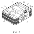
- FIG. 7 is a schematic view of a second preferred embodiment of the present invention.
- FIGS. 2 to 5 for a liquid-cooling heat dissipating device for dissipating heat by a casing of the present invention
- the device installs a casing 10 in any shape, and the casing 10 of this embodiment is a rectangular casing.
- An upper and lower side of the casing 10 are secured to a cover panel 11 a, 11 b, respectively.
- the cover panels 11 a, 11 b provided with a plurality of ventilation holes 111 a , 111 b .
- the side wall 18 at the lateral periphery of the casing 10 is a surrounding plate 19 with a plurality of liquid flow channels 12 and heat dissipating fins 13 .
- the liquid flow channels 12 are formed within the surrounding plate 19 parallelly and horizontally.
- the heat dissipating fins 13 perpendicularly extend from both sides of the surrounding plate of the side wall 18 , and are parallel to the liquid flow channels 12 .
- the side wall 18 has a gap 14 disposed at a predetermined position.
- a panel 15 is disposed in the gap 14 .
- a protruding ear 151 is protruded outward separately from both ends of the panel 15 .
- the protruding ears 151 separately have a lock hole 152 , such that the protruding ears 151 can be secured onto the edge of casing 10 on both sides of the gap 14 by a screw rod 153 passed through the lock hole 152 .
- the panel 15 can be embedded into the gap 14 of the casing 10 , and the panel 15 provided with a cold water connector 155 and a hot water connector 154 .
- the hot water connector 154 is connected to an end of the liquid flow channels 12
- the cold water connector 155 is connected to a cold water outlet 21 of a water tank 20 through a pipeline 16
- the water tank 20 is used for storing a liquid (which is water in this embodiment), and the water tank 20 can install a pump (not shown in the figure) for expediting the liquid flow.
- the water tank 20 comes with a cold water inlet 22 , connected to the other end of the liquid flow channels 12 .
- the cold and hot water connectors 155 , 154 are coupled to a water-cooling connector 30 through a pipeline 16 , and the water-cooling connector 30 can be installed in the casing 10 (as shown in FIG. 7 ) or outside the casing 10 (as shown in FIG. 6 ).
- the casing 10 further includes a decorative panel 17 thereon for the decoration purpose.
- the water-cooling connector 30 is installed at a heat source (such as a processor chip) in an external electronic device 40 , such that the liquid heated by the heat source can be sent to the liquid flow channels 12 through the pipeline 16 and flows into the case 10 .
- the heat from the heat source can be dissipated quickly to the outside through the heat dissipating fins 13 on the side wall 18 of the casing 10 , and the heated liquid is returned to the water tank 20 through the cold water inlet 22 and the liquid flow channel 12 , and then sent to the water-cooling connector 30 through the cold water outlet 21 , cold water connector 155 and pipeline 16 for repeated cycles, so as to dissipate heat produced by a heat source quickly to the outside, and the electronic equipment such as a computer or other electronic equipments can be operated at a more stable ambient temperature and applied to any electronic equipment. Referring to FIG.
- the water-cooling connector 30 is installed directly at a heat source (such as a processor) in the casing 10 (which could be a computer chassis), such that the liquid heated by the heat source is flowed into the liquid flow channel 12 through the pipeline 16 and the hot water connector 154 , and sent to the heat dissipating fins 13 between the liquid flow channels 12 , so that the heat can be dissipated quickly to the outside, and then the liquid is returned to the water tank 20 through the liquid flow channels 12 and the cold water inlet 22 , and then to the water- cooling connector 30 through the cold water outlet 21 , cold water connector 155 and pipeline 16 for repeated cycles, so as to dissipate the heat produced by the heat source to the outside quickly, and thus the heat will not remain at the heat source and in the casing 10 .
- a heat source such as a processor
Abstract
Description
Claims (6)
Priority Applications (1)
| Application Number | Priority Date | Filing Date | Title |
|---|---|---|---|
| US11/474,374 US7423875B2 (en) | 2006-06-26 | 2006-06-26 | Liquid-cooling heat dissipating device for dissipating heat by a casing |
Applications Claiming Priority (1)
| Application Number | Priority Date | Filing Date | Title |
|---|---|---|---|
| US11/474,374 US7423875B2 (en) | 2006-06-26 | 2006-06-26 | Liquid-cooling heat dissipating device for dissipating heat by a casing |
Publications (2)
| Publication Number | Publication Date |
|---|---|
| US20070297138A1 US20070297138A1 (en) | 2007-12-27 |
| US7423875B2 true US7423875B2 (en) | 2008-09-09 |
Family
ID=38873348
Family Applications (1)
| Application Number | Title | Priority Date | Filing Date |
|---|---|---|---|
| US11/474,374 Active 2026-10-24 US7423875B2 (en) | 2006-06-26 | 2006-06-26 | Liquid-cooling heat dissipating device for dissipating heat by a casing |
Country Status (1)
| Country | Link |
|---|---|
| US (1) | US7423875B2 (en) |
Cited By (5)
| Publication number | Priority date | Publication date | Assignee | Title |
|---|---|---|---|---|
| US20090213537A1 (en) * | 2005-03-30 | 2009-08-27 | Hush Technologies Investments Ltd | Housing for a Computer |
| US20100208428A1 (en) * | 2009-02-13 | 2010-08-19 | Asia Vital Components Co., Ltd. | Communication chassis heat dissipation structure |
| US20100315779A1 (en) * | 2009-06-16 | 2010-12-16 | Huang Chiu-Mao | Water-cooled communication chassis |
| US20120155015A1 (en) * | 2010-12-17 | 2012-06-21 | Gururaj Govindasamy | Heat dissipation unit for a wireless network device |
| US20220232731A1 (en) * | 2021-01-19 | 2022-07-21 | Nidec Corporation | Tank and cooling unit |
Families Citing this family (14)
| Publication number | Priority date | Publication date | Assignee | Title |
|---|---|---|---|---|
| EP1895824B1 (en) * | 2006-08-30 | 2009-04-01 | Siemens Aktiengesellschaft | Assembly for an automation device |
| DE102006041788B4 (en) * | 2006-09-06 | 2012-06-14 | Airbus Operations Gmbh | An aircraft electronics cooling device for an aircraft with a liquid cooling system |
| US20130284408A1 (en) * | 2012-04-30 | 2013-10-31 | Spx Corporation | Reservoir Cooling Apparaturs and Method |
| CN104144592B (en) * | 2013-05-09 | 2016-12-07 | 鸿富锦精密工业(深圳)有限公司 | Cooling system and be provided with the Cabinet-type server of this cooling system |
| DE202019100290U1 (en) | 2018-01-19 | 2019-06-24 | Lg Electronics Inc. | air cleaner |
| CN108897403A (en) * | 2018-09-21 | 2018-11-27 | 杨树楠 | A kind of host computer of fast cooling |
| CN109548383A (en) * | 2018-12-24 | 2019-03-29 | 南方电网科学研究院有限责任公司 | A kind of data acquisition device |
| CN110320984A (en) * | 2019-07-08 | 2019-10-11 | 合肥金新允电子技术有限公司 | A kind of fan-free built-in industrial control machine |
| CN111770665A (en) * | 2020-06-28 | 2020-10-13 | 广德姑苏线路板有限公司 | Assembled electronic efficient radiator |
| TW202231177A (en) * | 2021-01-29 | 2022-08-01 | 訊凱國際股份有限公司 | Computer device, case and water cooling device |
| CN113766776B (en) * | 2021-08-03 | 2023-03-24 | 联想(北京)有限公司 | Electronic device |
| CN114322627B (en) * | 2021-12-23 | 2023-11-14 | 武汉泰立德科技发展有限公司 | Multidirectional efficient heat dissipation device for petroleum machinery equipment |
| CN114415801B (en) * | 2022-03-22 | 2022-07-08 | 深圳市信步科技有限公司 | Integrated radiating computer motherboard |
| CN114531012B (en) * | 2022-04-21 | 2022-09-23 | 浙江日风电气股份有限公司 | Vehicle-mounted direct current converter packaging structure |
Citations (16)
| Publication number | Priority date | Publication date | Assignee | Title |
|---|---|---|---|---|
| US5469331A (en) * | 1994-04-07 | 1995-11-21 | Conway; Harry E. | Cooling system for modular power supply device |
| US5822187A (en) * | 1996-10-25 | 1998-10-13 | Thermal Corp. | Heat pipes inserted into first and second parallel holes in a block for transferring heat between hinged devices |
| US6097597A (en) * | 1998-06-30 | 2000-08-01 | Mitsubishi Denki Kabushiki Kaisha | Thermo-siphon and manufacturing method of thermo-siphon and information processing apparatus |
| US6199401B1 (en) * | 1997-05-07 | 2001-03-13 | Valeo Klimatechnik Gmbh & Co., Kg | Distributing/collecting tank for the at least dual flow evaporator of a motor vehicle air conditioning system |
| US20010042616A1 (en) * | 2000-03-21 | 2001-11-22 | Baer Daniel B. | Method and apparatus for cooling electronic enclosures |
| US6504719B2 (en) * | 2001-03-30 | 2003-01-07 | Intel Corporation | Computer system that can be operated without a cooling fan |
| US20030128511A1 (en) * | 2000-12-19 | 2003-07-10 | Hitachi, Ltd. | Liquid cooling system for all-in-one computer |
| US20030151892A1 (en) * | 2002-02-08 | 2003-08-14 | Hitachi, Ltd. | Liquid cooling system with structure for liquid supply and electric device |
| US6643132B2 (en) * | 2002-01-04 | 2003-11-04 | Intel Corporation | Chassis-level thermal interface component for transfer of heat from an electronic component of a computer system |
| US20040008490A1 (en) * | 2002-07-13 | 2004-01-15 | Kioan Cheon | Water cooling type soft cooling jacket for electronic device and buffer jacket using the same |
| US6687122B2 (en) * | 2001-08-30 | 2004-02-03 | Sun Microsystems, Inc. | Multiple compressor refrigeration heat sink module for cooling electronic components |
| US20040246677A1 (en) * | 2003-03-17 | 2004-12-09 | Shih-Tsung Chen | Computer cooling apparatus |
| US6979772B2 (en) * | 2003-05-14 | 2005-12-27 | Chaun-Choung Technology Corp. | Integrated heat dissipating enclosure for electronic product |
| US7028761B2 (en) * | 2003-10-15 | 2006-04-18 | Hsieh Kun Lee | Integrated liquid cooling system for electrical components |
| US7078619B2 (en) * | 2002-05-25 | 2006-07-18 | Geo-X Systems, Ltd. | Universal seismic data acquisition module |
| US7180747B2 (en) * | 2005-05-31 | 2007-02-20 | Cheng-Ping Lee | Heat dissipation device for a computer mother board |
-
2006
- 2006-06-26 US US11/474,374 patent/US7423875B2/en active Active
Patent Citations (16)
| Publication number | Priority date | Publication date | Assignee | Title |
|---|---|---|---|---|
| US5469331A (en) * | 1994-04-07 | 1995-11-21 | Conway; Harry E. | Cooling system for modular power supply device |
| US5822187A (en) * | 1996-10-25 | 1998-10-13 | Thermal Corp. | Heat pipes inserted into first and second parallel holes in a block for transferring heat between hinged devices |
| US6199401B1 (en) * | 1997-05-07 | 2001-03-13 | Valeo Klimatechnik Gmbh & Co., Kg | Distributing/collecting tank for the at least dual flow evaporator of a motor vehicle air conditioning system |
| US6097597A (en) * | 1998-06-30 | 2000-08-01 | Mitsubishi Denki Kabushiki Kaisha | Thermo-siphon and manufacturing method of thermo-siphon and information processing apparatus |
| US20010042616A1 (en) * | 2000-03-21 | 2001-11-22 | Baer Daniel B. | Method and apparatus for cooling electronic enclosures |
| US20030128511A1 (en) * | 2000-12-19 | 2003-07-10 | Hitachi, Ltd. | Liquid cooling system for all-in-one computer |
| US6504719B2 (en) * | 2001-03-30 | 2003-01-07 | Intel Corporation | Computer system that can be operated without a cooling fan |
| US6687122B2 (en) * | 2001-08-30 | 2004-02-03 | Sun Microsystems, Inc. | Multiple compressor refrigeration heat sink module for cooling electronic components |
| US6643132B2 (en) * | 2002-01-04 | 2003-11-04 | Intel Corporation | Chassis-level thermal interface component for transfer of heat from an electronic component of a computer system |
| US20030151892A1 (en) * | 2002-02-08 | 2003-08-14 | Hitachi, Ltd. | Liquid cooling system with structure for liquid supply and electric device |
| US7078619B2 (en) * | 2002-05-25 | 2006-07-18 | Geo-X Systems, Ltd. | Universal seismic data acquisition module |
| US20040008490A1 (en) * | 2002-07-13 | 2004-01-15 | Kioan Cheon | Water cooling type soft cooling jacket for electronic device and buffer jacket using the same |
| US20040246677A1 (en) * | 2003-03-17 | 2004-12-09 | Shih-Tsung Chen | Computer cooling apparatus |
| US6979772B2 (en) * | 2003-05-14 | 2005-12-27 | Chaun-Choung Technology Corp. | Integrated heat dissipating enclosure for electronic product |
| US7028761B2 (en) * | 2003-10-15 | 2006-04-18 | Hsieh Kun Lee | Integrated liquid cooling system for electrical components |
| US7180747B2 (en) * | 2005-05-31 | 2007-02-20 | Cheng-Ping Lee | Heat dissipation device for a computer mother board |
Cited By (9)
| Publication number | Priority date | Publication date | Assignee | Title |
|---|---|---|---|---|
| US20090213537A1 (en) * | 2005-03-30 | 2009-08-27 | Hush Technologies Investments Ltd | Housing for a Computer |
| US20100208428A1 (en) * | 2009-02-13 | 2010-08-19 | Asia Vital Components Co., Ltd. | Communication chassis heat dissipation structure |
| US7800907B2 (en) * | 2009-02-13 | 2010-09-21 | Asia Vital Components Co., Ltd. | Communication chassis heat dissipation structure |
| US20100315779A1 (en) * | 2009-06-16 | 2010-12-16 | Huang Chiu-Mao | Water-cooled communication chassis |
| US8081463B2 (en) * | 2009-06-16 | 2011-12-20 | Asia Vital Components Co., Ltd. | Water-cooled communication chassis |
| US8422231B2 (en) | 2009-06-16 | 2013-04-16 | Asia Vital Components Co., Ltd. | Water-cooled communication chassis |
| US20120155015A1 (en) * | 2010-12-17 | 2012-06-21 | Gururaj Govindasamy | Heat dissipation unit for a wireless network device |
| US8681501B2 (en) * | 2010-12-17 | 2014-03-25 | Aruba Networks, Inc. | Heat dissipation unit for a wireless network device |
| US20220232731A1 (en) * | 2021-01-19 | 2022-07-21 | Nidec Corporation | Tank and cooling unit |
Also Published As
| Publication number | Publication date |
|---|---|
| US20070297138A1 (en) | 2007-12-27 |
Similar Documents
| Publication | Publication Date | Title |
|---|---|---|
| US7423875B2 (en) | Liquid-cooling heat dissipating device for dissipating heat by a casing | |
| EP1881394A1 (en) | Liquid-cooling heat dissipating device for dissipating heat by a casing | |
| US7990713B2 (en) | Heat dissipation device and method for manufacturing the same | |
| US8439632B2 (en) | Thermal module with airflow guiding function | |
| US20120155021A1 (en) | Air duct and electronic device having the same | |
| US8355253B2 (en) | Electronic apparatus with heat dissipation device | |
| TW201143585A (en) | Electronic device | |
| US20070242428A1 (en) | Structure for fixing fan with computer casing | |
| US9320176B2 (en) | Heat dissipation system and rack-mount server using the same | |
| US6913069B2 (en) | Cooling device having fins arranged to funnel air | |
| TW201538063A (en) | Electronic device and cooling fan thereof | |
| TW201625895A (en) | Heat dissipating device and heat dissipating system | |
| TWI518490B (en) | Thermal heat dissipating structure | |
| TW201304671A (en) | Heat sink assembly | |
| TW200930275A (en) | Heat dissipation device | |
| CN210119749U (en) | Heat dissipation device and notebook computer | |
| US20130168061A1 (en) | Heat dissipation assembly | |
| US20140174699A1 (en) | Heat dissipation assembly | |
| TWI337699B (en) | Heat dissipation device | |
| TWM325536U (en) | Heat dissipater | |
| TWI312653B (en) | Heat dissipation device | |
| TWI336234B (en) | Heat dissipation device | |
| KR101087861B1 (en) | A heat source cooling structure for computer | |
| TW201624186A (en) | Heating dissipation device | |
| JPH10107469A (en) | Cooling device for heat accumulated part and electronic device |
Legal Events
| Date | Code | Title | Description |
|---|---|---|---|
| AS | Assignment |
Owner name: SILVER-STONE TECHNOLOGY CO., LTD., TAIWAN Free format text: ASSIGNMENT OF ASSIGNORS INTEREST;ASSIGNORS:HUANG, HSIN-SHENG;CHI, YEN-SHU;REEL/FRAME:018033/0386 Effective date: 20060614 |
|
| STCF | Information on status: patent grant |
Free format text: PATENTED CASE |
|
| FPAY | Fee payment |
Year of fee payment: 4 |
|
| FPAY | Fee payment |
Year of fee payment: 8 |
|
| MAFP | Maintenance fee payment |
Free format text: PAYMENT OF MAINTENANCE FEE, 12TH YR, SMALL ENTITY (ORIGINAL EVENT CODE: M2553); ENTITY STATUS OF PATENT OWNER: SMALL ENTITY Year of fee payment: 12 |