US7422283B2 - Child restraint system and method for monitoring installation of the child restraint system - Google Patents
Child restraint system and method for monitoring installation of the child restraint system Download PDFInfo
- Publication number
- US7422283B2 US7422283B2 US11/146,926 US14692605A US7422283B2 US 7422283 B2 US7422283 B2 US 7422283B2 US 14692605 A US14692605 A US 14692605A US 7422283 B2 US7422283 B2 US 7422283B2
- Authority
- US
- United States
- Prior art keywords
- tension value
- child
- seat belt
- restraint system
- seat
- Prior art date
- Legal status (The legal status is an assumption and is not a legal conclusion. Google has not performed a legal analysis and makes no representation as to the accuracy of the status listed.)
- Active, expires
Links
- 238000000034 method Methods 0.000 title claims abstract description 53
- 238000012544 monitoring process Methods 0.000 title claims abstract description 25
- 238000009434 installation Methods 0.000 title claims abstract description 13
- 230000001939 inductive effect Effects 0.000 claims description 11
- 239000004973 liquid crystal related substance Substances 0.000 claims description 6
- 230000001965 increasing effect Effects 0.000 description 13
- 230000003247 decreasing effect Effects 0.000 description 9
- 239000003990 capacitor Substances 0.000 description 5
- 239000000463 material Substances 0.000 description 5
- 238000004590 computer program Methods 0.000 description 4
- 230000004044 response Effects 0.000 description 4
- 230000008901 benefit Effects 0.000 description 3
- 238000010586 diagram Methods 0.000 description 3
- 210000001217 buttock Anatomy 0.000 description 2
- 210000002414 leg Anatomy 0.000 description 2
- 101100521334 Mus musculus Prom1 gene Proteins 0.000 description 1
- 238000004891 communication Methods 0.000 description 1
- 238000010276 construction Methods 0.000 description 1
- 238000009429 electrical wiring Methods 0.000 description 1
- 238000012986 modification Methods 0.000 description 1
- 230000004048 modification Effects 0.000 description 1
- 230000003287 optical effect Effects 0.000 description 1
- 229920000728 polyester Polymers 0.000 description 1
- 238000012545 processing Methods 0.000 description 1
Images


Classifications
-
- B—PERFORMING OPERATIONS; TRANSPORTING
- B60—VEHICLES IN GENERAL
- B60N—SEATS SPECIALLY ADAPTED FOR VEHICLES; VEHICLE PASSENGER ACCOMMODATION NOT OTHERWISE PROVIDED FOR
- B60N2/00—Seats specially adapted for vehicles; Arrangement or mounting of seats in vehicles
- B60N2/24—Seats specially adapted for vehicles; Arrangement or mounting of seats in vehicles for particular purposes or particular vehicles
- B60N2/26—Seats specially adapted for vehicles; Arrangement or mounting of seats in vehicles for particular purposes or particular vehicles for children
- B60N2/28—Seats readily mountable on, and dismountable from, existing seats or other parts of the vehicle
- B60N2/2821—Seats readily mountable on, and dismountable from, existing seats or other parts of the vehicle having a seat and a base part
-
- B—PERFORMING OPERATIONS; TRANSPORTING
- B60—VEHICLES IN GENERAL
- B60N—SEATS SPECIALLY ADAPTED FOR VEHICLES; VEHICLE PASSENGER ACCOMMODATION NOT OTHERWISE PROVIDED FOR
- B60N2/00—Seats specially adapted for vehicles; Arrangement or mounting of seats in vehicles
- B60N2/24—Seats specially adapted for vehicles; Arrangement or mounting of seats in vehicles for particular purposes or particular vehicles
- B60N2/26—Seats specially adapted for vehicles; Arrangement or mounting of seats in vehicles for particular purposes or particular vehicles for children
- B60N2/28—Seats readily mountable on, and dismountable from, existing seats or other parts of the vehicle
- B60N2/2803—Adaptations for seat belts
- B60N2/2806—Adaptations for seat belts for securing the child seat to the vehicle
-
- B—PERFORMING OPERATIONS; TRANSPORTING
- B60—VEHICLES IN GENERAL
- B60N—SEATS SPECIALLY ADAPTED FOR VEHICLES; VEHICLE PASSENGER ACCOMMODATION NOT OTHERWISE PROVIDED FOR
- B60N2/00—Seats specially adapted for vehicles; Arrangement or mounting of seats in vehicles
- B60N2/24—Seats specially adapted for vehicles; Arrangement or mounting of seats in vehicles for particular purposes or particular vehicles
- B60N2/26—Seats specially adapted for vehicles; Arrangement or mounting of seats in vehicles for particular purposes or particular vehicles for children
- B60N2/28—Seats readily mountable on, and dismountable from, existing seats or other parts of the vehicle
- B60N2/2803—Adaptations for seat belts
- B60N2002/2815—Adaptations for seat belts with additional belt accessories, e.g. a belt tension detector
-
- B—PERFORMING OPERATIONS; TRANSPORTING
- B60—VEHICLES IN GENERAL
- B60R—VEHICLES, VEHICLE FITTINGS, OR VEHICLE PARTS, NOT OTHERWISE PROVIDED FOR
- B60R22/00—Safety belts or body harnesses in vehicles
- B60R22/48—Control systems, alarms, or interlock systems, for the correct application of the belt or harness
- B60R2022/4808—Sensing means arrangements therefor
- B60R2022/4841—Sensing means arrangements therefor for sensing belt tension
Definitions
- This application relates to a child restraint system and a method for monitoring installation of the child restraint system.
- Child restraint systems have been utilized to hold infants or children therein within vehicles.
- a first type of child restraint system includes a child seat and a base portion for holding the seat, that are rearward-facing with respect to a vehicle seat. In this type of child restraint system, the child seat is secured in the base portion and a vehicle seat belt webbing is used to secure the base portion to the vehicle seat.
- a second type of child restraint system utilizes a rearward-facing child seat that is secured via the vehicle seat belt webbing to the vehicle seat.
- a third type of child restraint system is a booster child seat that is frontward-facing with respect to the vehicle seat and is secured via the vehicle seat belt webbing to the vehicle seat.
- the inventors herein have recognized a need for a child restraint system that can notify a person when a desired amount of tension is being applied to the vehicle seat belt webbing when securing a child restraint system on a vehicle seat.
- the child restraint system includes a child seat configured to receive a child occupant.
- the child seat has at least a first seat belt guide member configured to engage a vehicle seat belt webbing for securing the child seat to a vehicle seat.
- the child restraint system further includes a first sensor coupled to the first seat belt guide member.
- the first sensor is configured to output a first signal indicative of an amount of tension being applied to the vehicle seat belt webbing.
- the child restraint system further includes a controller coupled to the child seat configured to receive the first signal and to compute a first tension value based on the first signal.
- the controller further is configured to induce a first device disposed on the child seat to indicate when the first tension value is less than a predetermined tension value.
- a method for monitoring installation of a child restraint system on a vehicle seat in accordance with another exemplary embodiment is provided.
- the child restraint system has a child seat configured to receive a child occupant.
- the child seat has at least a first seat belt guide member configured to engage a vehicle seat belt webbing for securing the child seat to the vehicle seat.
- the method includes outputting a first signal from a first sensor disposed on the first seat belt guide member of the child seat.
- the first signal is indicative of an amount of tension being applied to the vehicle seat belt webbing.
- the method further includes computing a first tension value based on the first signal utilizing a controller.
- the method further includes inducing a first device disposed on the child seat to indicate when the first tension value is less than a predetermined tension value, utilizing the controller.
- FIG. 1 is a diagram of a child restraint system in accordance with exemplary embodiment
- FIG. 2 is a top view of a base portion of the child restraint system of FIG. 1 ;
- FIG. 3 is enlarged view of a portion of a child seat of the child restraint system of FIG. 1 ;
- FIG. 4 is an electrical schematic of a seat belt tension monitoring system utilized in the child restraint system of FIG. 1 ;
- FIG. 5 is a schematic of a force sensor utilized in the seat belt tension monitoring system of FIG. 4 ;
- FIG. 6 is a diagram of a portion of the force sensor of FIG. 5 ;
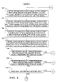
- FIG. 7 is a plot of the curve indicating electrical resistance versus force characteristics of the force sensor of FIG. 5 ;
- FIGS. 8-10 are flowcharts of a method for monitoring installation of the child restraint system of FIG. 1 ;
- FIG. 11 is a diagram of a child restraint system in accordance with another exemplary embodiment.
- a child restraint system 10 that can be secured to a vehicle seat 12 in accordance with exemplary embodiment is provided.
- the child restraint system 10 is secured to the vehicle seat 12 utilizing the vehicle seat belt webbing 14 .
- the child restraint system 10 includes a child seat 20 , a base portion 22 , and a seat belt tension monitoring system 24 .
- the child seat 20 comprises a rearward facing child seat that is configured to accommodate a child therein for transporting the child both inside and outside of a vehicle.
- the child seat 20 is configured to be fixedly secured to the base portion 22 and the base portion 22 is further secured via the vehicle seat belt webbing 14 to the seat 12 or to a frame of a vehicle.
- the child seat 20 includes a shell 30 , the handle 31 , and a cushion 32 .
- the shell 30 is constructed from a rigid polymeric material and defines a compartment for accommodating the child.
- the shell 30 includes a back portion 33 , a seat portion 34 , and a pair of seat belt guide members 36 .
- the back portion 33 supports a back of the child and the seat portion 34 supports the buttocks and legs of the child.
- a compartment defined by the shell 34 is lined with the cushion 32 .
- the pair of seat belt guide members 36 (one of which shown in FIG. 1 ) are disposed on opposite sides of the shell 30 and are configured to form an inner groove for receiving the vehicle seat belt webbing 14 therethrough.
- the handle 31 is coupled to shell 30 and is provided to allow a user to easily lift the child seat 20 .
- the handle 31 is constructed from a rigid polymeric material.
- the base portion 22 is provided to receive the child seat 20 therein.
- the base portion 22 has a shell 50 constructed from a rigid polymeric material.
- the shell 50 includes a bottom wall 52 , and sidewalls 58 , 60 coupled to the bottom wall 52 .
- the side walls 58 , 60 include apertures 54 , 56 , respectively, extending therethrough for receiving the vehicle seat belt webbing 14 .
- the bottom wall 52 includes a seat belt guide portion 70 for guiding vehicle seat belt webbing 14 from the aperture 54 in the side wall 58 to the aperture 56 in the side wall 60 .
- the seat belt tension monitoring system 24 is provided to monitor a tension of the vehicle seat belt webbing 14 and to provide an indication to a user as to whether the tension is less than or greater than a predetermined tension value.
- the seat belt tension monitoring system 24 includes a controller 80 , force sensors 82 , 84 , 86 , 88 , resistors 90 , 92 , 94 , 96 , 98 , 100 , 102 , 104 capacitors 110 , 112 , 114 , 116 , light emitting diodes (LEDs) 130 , 132 , an annunciator 134 , a liquid crystal display (LCD) 136 , and a switch 137 .
- LEDs light emitting diodes
- the controller 80 is provided to monitor the output of the force sensors 82 , 84 , 86 , 88 and to calculate a tension applied to the vehicle seat belt webbing 14 .
- the controller 80 is further provided to control operation of the indicator devices including the LEDs 130 , 132 , the annunciator 134 , and the LCD 136 , as will be described in greater detail below.
- the controller 80 includes a central processing unit (CPU) 140 , a read-only memory (ROM) 142 , a volatile memory such as a random access memory (RAM) 144 and an input/output (I/O) interface 146 .
- the CPU 140 operably communicates with the ROM 142 , the RAM 144 , and the I/O interface 146 .
- the computer readable media including ROM 142 and RAM 144 may be implemented using any of a number of known memory devices such as PROMs, EPROMs, EEPROMS, flash memory or any other electric, magnetic, optical or combination memory device capable of storing data, some of which represent executable instructions used by the CPU 140 .
- the force sensors 82 , 84 , 86 , 88 are provided to output signals (V 1 ), (V 2 ), (V 3 ), (V 4 ), respectively, indicative of a tension be applied to the vehicle seat belt webbing 14 .
- the force sensors 82 , 84 , 86 , 88 comprise piezo-resistive force sensors and have an identical construction with one another.
- a curve 186 indicates an operational characteristics of each of the force sensors 82 , 84 , 86 , 88 . In particular, the curve 186 indicates that as a force applied to a force sensor is increased, a resistance of the force sensor is decreased.
- the force sensors 82 , 84 , 86 , 88 can comprise any other type of force sensor known to those skilled and the art, that is capable of detecting a tension applied to the vehicle seat belt webbing 14 .
- the force sensors 82 , 84 are disposed proximate the pair of seat belt guide members 36 , respectively.
- the force sensors 86 , 88 are disposed on the seat belt guide member 70 between the seat belt guide member and the vehicle seat belt webbing 14 .
- the force sensor 82 will be explained.
- the force sensor 82 includes a frame portion 160 , a deflection member 162 , a force sensor strip 164 , and a contact 166 .
- the frame portion 160 includes slots 170 , 174 disposed therethrough on opposite sides of the deflection member 162 for receiving the vehicle seat belt webbing 14 is therethrough.
- the frame portion 160 can be either integrally molded within the shell 30 of the child seat 20 or fixedly attached to the shell 30 .
- the frame portion 160 is operably coupled to the deflection member 162 at pivot points 168 , 170 which are adjacent the slots 172 , 174 , respectively.
- the vehicle seat belt webbing 14 routed over the surface 176 and through the slot 172 and further routed over the underside surface 178 of the deflection member 162 . Thereafter, the vehicle seat belt webbing 14 is routed through the slot 174 and over the surface 176 on an opposite side of the frame portion 160 .
- the force sensor strip 164 is disposed on the surface 176 of the deflection member 162 a predetermined distance from the stationary contact 166 .
- the force sensor strip 164 includes a conductive ink layer 184 that is disposed between polyester layers 180 , 182 .
- the vehicle seat belt webbing 14 applies a substantially perpendicular force against the deflection member 162 that induces the member 162 to move towards the stationary contact 166 .
- the stationary contact 166 is fixedly coupled to the shell 33 .
- the force sensor strip 164 disposed on the deflection member 162 When the force sensor strip 164 disposed on the deflection member 162 is pushed against the contact 166 , a force applied to the force sensor strip 164 reduces a resistance of the conductive ink layer 84 that is proportional to the applied force. Accordingly, the resistance of the conductive ink layer 84 is proportional to the force being applied to the force sensor strip 164 by the vehicle seat belt webbing 14 , that is further proportional to the tension being applied to the vehicle seat belt webbing 14 .
- the resistor 90 is electrically coupled between a node 118 and the I/O interface 146 .
- the capacitor 110 is electrically coupled between the node 118 and electrical ground.
- the resistor 92 is electrically coupled between a voltage source Vdd and the node 118 .
- the force sensor 82 is electrically coupled between the node 118 and the electrical ground.
- the conductive ink layer 184 of the force sensor strip 162 in the force sensor 82 is electrically coupled between the node 118 and the electrical ground.
- a resistance of conductive ink layer 184 is decreased which results in an amplitude of the voltage signal (V 1 ) being decreased.
- a resistance of conductive ink layer 184 is increased which results in an amplitude of the voltage signal (V 1 ) being increased.
- the resistor 94 is electrically coupled between a node 120 and the I/O interface 146 .
- the capacitor 112 is electrically coupled between the node 120 and electrical ground.
- the resistor 96 is electrically coupled between a voltage source Vdd and the node 120 .
- the force sensor 84 is electrically coupled between the node 120 and the electrical ground.
- a conductive ink layer of the force sensor strip in the force sensor 84 is electrically coupled between the node 120 and the electrical ground.
- the resistor 98 is electrically coupled between a node 122 and the I/O interface 146 .
- the capacitor 114 is electrically coupled between the node 122 and electrical ground.
- the resistor 100 is electrically coupled between a voltage source Vdd and the node 122 .
- the force sensor 86 is electrically coupled between the node 122 and the electrical ground.
- a conductive ink layer of the force sensor strip in the force sensor 86 is electrically coupled between the node 122 and the electrical ground.
- the resistor 102 is electrically coupled between a node 124 and the I/O interface 146 .
- the capacitor 116 is electrically coupled between the node 124 and electrical ground.
- the resistor 104 is electrically coupled between a voltage source Vdd and the node 124 .
- the force sensor 88 is electrically coupled between the node 124 and the electrical ground.
- a conductive ink layer of the force sensor strip in the force sensor 80 is electrically coupled between the node 124 and the electrical ground.
- the force sensors 86 , 88 are electrically coupled to the controller 80 through an electrical wiring harness (not shown), using a plug and a socket to allow the child seat 20 to be detached from the base portion 22 .
- the force sensors 86 , 88 are operably coupled to one or more radio frequency (RF) transmitters that transmit RF signals having information indicative of the measured tension
- the seat belt tension monitoring system 24 includes an RF receiver operably coupled to the controller 80 configured to receive the RF signals, to allow wireless communication therebetween.
- RF radio frequency
- the LED 130 is provided to emit light having a first color to indicate when a measured tension of the vehicle seat belt webbing 14 is greater than or equal to the predetermined tension value.
- the LED 132 is provided to emit light having a second color to indicate when a measured tension of the vehicle seat belt webbing is less than a predetermined tension value. As shown, the LEDs 130 , 132 are electrically coupled between the I/O interface 146 and electrical ground.
- the electrical annunciator 134 is provided to emit a first audible sound when a measured tension of the vehicle seat belt webbing 14 is less than a predetermined tension value, in response to a control signal from the controller 80 .
- the electrical annunciator 134 is further provided to emit a second audible sound when a measured tension of the vehicle seat belt webbing 14 is greater than or equal to the predetermined tension value, in response to another control signal from the controller 80 .
- the annunciator 134 is electrically coupled to the I/O interface 146 .
- the LCD 136 is provided to display a first message when a measured tension of the vehicle seat belt webbing 14 is less than a predetermined tension value, in response to a control signal from the controller 80 .
- the LCD 136 is further provided to display a second message when a measured tension of the vehicle seat belt webbing 14 is greater than or equal to the predetermined tension value, in response to a control signal from the controller 80 .
- the LCD 136 is electrically coupled to the I/O interface 146 .
- the switch 137 is provided to induce the controller 80 to monitor installation of the child restraint system 10 in accordance with the method of FIGS. 8-10 . In particular, when the switch 137 is moved to a closed operational position, the controller 80 monitors installation of the child restraint system 10 .
- the switch 137 is electrically coupled to the I/O interface 146 .
- a single force sensor could be utilized in the child seat 20 and a single force sensor could be utilized in the base portion 22 .
- another type of force sensor such as a piezo-resistive sensor, could be used in place of the conductive ink sensors 82 , 84 , 86 , and 88 .
- one type of indicator e.g., LED or annunciator or LCD
- LED or annunciator or LCD could be utilized to indicate whether the amount of tension being applied to the vehicle seat belt webbing 14 is less than a predetermined tension value or greater than or equal to the predetermined tension value.
- FIGS. 8-10 a method for monitoring installation of the child restraint system 10 is illustrated.
- the method can be implemented utilizing software algorithms executed by the controller 80 of the seat belt monitoring system 24 .
- the controller 80 samples a signal (V 1 ) output from the force sensor 82 disposed proximate a first seat belt guide member 36 on the child seat 20 and calculates a first tension value based on the signal (V 1 ).
- the controller 80 samples a signal (V 2 ) output from a force sensor 84 disposed proximate a second seat belt guide member 36 on the child seat 20 and calculates a second tension value based on the signal (V 2 ).
- the controller 80 samples a signal (V 3 ) output from a force sensor 86 disposed on a seat belt guide portion 70 of a base portion 22 and calculates a third tension value based on the signal (V 3 ).
- the controller 80 samples a signal (V 4 ) output from a force sensor 88 disposed on the seat belt guide portion 70 of the base portion 22 and calculates a fourth tension value based on the signal (V 4 ).
- step 198 the controller 80 makes a determination as to whether: (i) the first tension value is less than a predetermined tension value, and (ii) the second tension value is less than a predetermined tension value. If the value of step 198 equals “yes”, the method advances to step 200 . Otherwise, the method advances to step 214 .
- step 200 the controller 80 makes a determination as to whether: (i) the third tension value is less than the predetermined tension value, and (ii) the fourth tension value is less than in the predetermined tension value. If the value of step 200 equals “yes”, the method advances to step 202 . Otherwise, the method advances to step 214 .
- step 202 the controller 80 makes a determination as to whether the child seat 10 has LEDs 130 , 132 . If the value of step 202 equals “yes”, the method advances to step 204 . Otherwise, the method advances to step 206 .
- step 204 the controller 80 induces the LED 130 to emit light having a first color indicating an amount of tension being applied to the vehicle seat belt webbing 14 is less than the predetermined tension value.
- step 206 the method advances to step 206 .
- step 206 the controller 80 makes a determination as to whether the child seat 20 has an annunciator 134 . If the value of step 206 equals “yes”, the method advances step 208 . Otherwise, the method advances to step 210 .
- step 208 the controller 80 induces the annunciator 134 to emit a first audible sound indicating an amount of tension being applied to the vehicle seat belt webbing 14 is less than the predetermined tension value.
- step 210 the controller 80 makes a determination as to whether the child seat 20 has an LCD 136 . If the value of step 210 equals “yes”, the method advances to step 212 . Otherwise, method advances to step 190 .
- step 212 the controller 80 induces the LCD 136 to display a first message indicating an amount of tension being applied to the vehicle seat belt webbing is less than the predetermined tension value.
- step 212 the method advances to step 190 .
- step 214 when the value of either of the steps equals “no”, the method advances to step 214 .
- step 214 the controller 80 makes a determination as to whether the child seat 20 has the LEDs 130 , 132 . If the value of step 214 equals “yes”, the method advances to step 216 . Otherwise, the method advances to step 218 .
- step 216 the controller 80 induces the LED 132 to emit light having a second color indicating an amount of tension being applied to the vehicle seat belt webbing 14 is greater than or equal to the predetermined tension value.
- step 216 the method advances to step 218 .
- step 218 the controller 80 makes a determination as to whether the child seat 20 has the annunciator 134 . If the value of step 218 equals “yes”, the method advances to step 220 . Otherwise, the method advances to step 222 .
- step 220 the controller 80 induces the annunciator 134 to emit a second audible sound indicating an amount of tension being applied to the vehicle seat belt webbing 14 is greater than or equal to the predetermined tension value.
- step 220 the method advances to step 222 .
- step 222 the controller 80 makes a determination as to whether the child seat 20 has the LCD 136 . If the value of step 222 equals “yes”, the method advances to step 224 . Otherwise, the method advances to step 190 .
- step 224 the controller 80 induces the LCD 136 to display a second message indicating an amount of tension being applied to the vehicle seat belt webbing 14 is greater than or equal to the predetermined tension value.
- step 224 method advances to step 190 .
- a child restraint system 230 that can be secured to a vehicle seat 12 in accordance with another exemplary embodiment is provided.
- the child restraint system 230 is secured to the vehicle seat 12 utilizing the vehicle seat belt webbing 14 .
- the child restraint system 230 includes a child seat 232 and a portion of a seat belt tension monitoring system 24 .
- the child seat 232 comprises a frontward-facing child seat that is configured to accommodate a child therein for transporting the child inside of a vehicle.
- the child seat 232 is configured to be fixedly secured via the vehicle seat belt webbing 14 to the seat 12 or to a frame of a vehicle.
- the child seat 232 includes a shell 234 and a cushion 235 .
- the shell 234 is constructed from a rigid polymeric material and defines a compartment for accommodating the child.
- the shell 234 includes a back portion 236 , a seat portion 238 , and a seat belt guide member (not shown) disposed in the back portion 236 .
- the back portion 236 supports a back of the child and the seat portion 238 supports the buttocks and legs of the child.
- a compartment defined by the shell 234 is lined with the cushion 235 .
- the back portion 236 includes an aperture 240 extending therethrough for receiving the vehicle seat belt webbing 14 therethrough.
- the child restraint system 230 can utilize substantially all of the component of the seat belt tension monitoring system 24 , except for the force sensors 86 , 88 , and the associated components provided to supply the voltage signals (V 3 ), (V 4 ) to the controller 80 . It particular, the force sensors 82 , 84 can be disposed on the back portion 236 proximate the aperture 240 to contact the vehicle seat belt webbing 14 for monitoring a seat belt tension applied to the vehicle seat belt webbing 14 , as described above with respect to the child restraint system 10 .
- the child restraint system and a method for monitoring installation of the child restraint system provides a substantial advantage over other systems and methods.
- the child restraint system utilizes a controller to monitor the amount of tension being applied to the vehicle seat belt webbing when securing the child restraint system on a vehicle seat. Further, the controller induces at least one indicator device to notify a person when a desired amount of tension is being applied to vehicle seat belt webbing.
- the method for monitoring installation of the child restraint system can be embodied in the form of computer-implemented processes and apparatuses for practicing those processes.
- the method is embodied in computer program code executed by one or more elements.
- the present method may be embodied in the form of computer program code containing instructions embodied in tangible media, such as floppy diskettes, CD-ROMs, hard drives, flash memory, or any other computer-readable storage medium, wherein, when the computer program code is loaded into and executed by a computer, the computer becomes an apparatus for practicing the invention.
- the present method can also be embodied in the form of computer program code, for example, whether stored in a storage medium, loaded into and/or executed by a computer.
Abstract
Description
Claims (19)
Priority Applications (1)
| Application Number | Priority Date | Filing Date | Title |
|---|---|---|---|
| US11/146,926 US7422283B2 (en) | 2004-06-07 | 2005-06-06 | Child restraint system and method for monitoring installation of the child restraint system |
Applications Claiming Priority (3)
| Application Number | Priority Date | Filing Date | Title |
|---|---|---|---|
| US57754604P | 2004-06-07 | 2004-06-07 | |
| US60798804P | 2004-09-08 | 2004-09-08 | |
| US11/146,926 US7422283B2 (en) | 2004-06-07 | 2005-06-06 | Child restraint system and method for monitoring installation of the child restraint system |
Publications (2)
| Publication Number | Publication Date |
|---|---|
| US20050275276A1 US20050275276A1 (en) | 2005-12-15 |
| US7422283B2 true US7422283B2 (en) | 2008-09-09 |
Family
ID=35459800
Family Applications (1)
| Application Number | Title | Priority Date | Filing Date |
|---|---|---|---|
| US11/146,926 Active 2026-05-07 US7422283B2 (en) | 2004-06-07 | 2005-06-06 | Child restraint system and method for monitoring installation of the child restraint system |
Country Status (1)
| Country | Link |
|---|---|
| US (1) | US7422283B2 (en) |
Cited By (17)
| Publication number | Priority date | Publication date | Assignee | Title |
|---|---|---|---|---|
| US20090160232A1 (en) * | 2007-12-20 | 2009-06-25 | Hinze Lee R | Child seat and method for monitoring installation of the child seat |
| US20090177357A1 (en) * | 2008-01-09 | 2009-07-09 | International Business Machines Corporation | Feedback loop system for passenger safety |
| US20100140997A1 (en) * | 2008-12-04 | 2010-06-10 | Cosco Management, Inc. | Automobile Seat for Children With Visual Indicator of Harness Tightness and Corresponding Visual Indicator |
| US20100253498A1 (en) * | 2009-04-02 | 2010-10-07 | Ford Global Technologies, Llc | Child seat monitoring system |
| US20110089726A1 (en) * | 2009-10-16 | 2011-04-21 | Summer Infant (Usa), Inc. | Car seat with integrated level indicator |
| US8151654B2 (en) | 1998-04-01 | 2012-04-10 | Methode Electronics, Inc. | Sensor pad for controlling airbag deployment and associated support |
| US20120104826A1 (en) * | 2010-09-15 | 2012-05-03 | Amsafe Commercial Products, Inc. | Occupant restraint system components having status indicators and/or media interfaces, and associated methods of use and manufacture |
| US20130082498A1 (en) * | 2011-09-30 | 2013-04-04 | Graco Children's Products Inc. | Belt Path Selection Apparatus |
| US8827364B2 (en) | 2011-11-30 | 2014-09-09 | Seatcure, Llc | Child carrier restraint system |
| US8840184B2 (en) | 2011-10-06 | 2014-09-23 | Thorley Industries Llc | Child restraint system with automated installation |
| US20140284975A1 (en) * | 2013-03-20 | 2014-09-25 | Maria Nelly Manimbo | Talking Car Seat |
| US20150069802A1 (en) * | 2012-04-04 | 2015-03-12 | Sakta Ab | High back booster seat/child restraint |
| US9751433B2 (en) | 2011-10-06 | 2017-09-05 | Thorley Industries Llc | Child restraint system with user interface |
| US9781977B2 (en) | 2015-08-11 | 2017-10-10 | Shield Restraint Systems, Inc. | Interlocking web connectors for occupant restraint systems and associated methods of use and manufacture |
| US10357083B2 (en) | 2016-09-16 | 2019-07-23 | Shield Restraint Systems, Inc. | Buckle assemblies and associated systems and methods for use with child seats and other restraint systems |
| US11124152B2 (en) | 2018-11-20 | 2021-09-21 | Shield Restraint Systems, Inc. | Buckle assemblies for use with child seats and other personal restraint systems |
| US20220396184A1 (en) * | 2019-11-18 | 2022-12-15 | Wonderland Switzerland Ag | Tether assembly, and child safety seat and support structure thereof |
Families Citing this family (12)
| Publication number | Priority date | Publication date | Assignee | Title |
|---|---|---|---|---|
| US7478875B2 (en) * | 2004-06-07 | 2009-01-20 | Delphi Technologies, Inc. | Child restraint system and method for monitoring installation of the child restraint system |
| WO2006020604A2 (en) * | 2004-08-09 | 2006-02-23 | Delphi Technologies, Inc. | Child restraint system comprising event data recorder |
| EP1791718B1 (en) * | 2004-09-08 | 2014-10-29 | Delphi Technologies Inc. | Child restraint system |
| US20080246316A1 (en) * | 2007-04-03 | 2008-10-09 | David Shaun Carine | Child restraint system including tension sensor and status indicator |
| EP2203760A1 (en) * | 2007-10-19 | 2010-07-07 | Nxp B.V. | Processing of satellite positioning system signals |
| CN104290712B (en) * | 2014-08-22 | 2017-09-05 | 好孩子儿童用品有限公司 | A kind of drawstring tenses indication mechanism and the automobile seat for child with it |
| FR3027260B1 (en) * | 2014-10-16 | 2018-02-16 | Louis DEVELAY | DEVICE FOR MONITORING THE TENSION OF THE HARNESS OF A CHILD SEAT |
| US20170088096A1 (en) * | 2015-09-24 | 2017-03-30 | Intel IP Corporation | Seat safety apparatus with a resilient sensor |
| US10071654B2 (en) * | 2015-10-05 | 2018-09-11 | Mcleanics Technology Corporation | Baby alert car seat alarm—smart car seat |
| IT201700058221A1 (en) * | 2017-05-29 | 2018-11-29 | Artsana Spa | Base of a car seat for a child |
| CN114194084A (en) * | 2020-09-17 | 2022-03-18 | 宝钜瑞士股份有限公司 | Child safety seat |
| AU2021201211B1 (en) | 2021-02-24 | 2021-08-12 | BRITAX RÖMER Kindersicherheit GmbH | Child restraint |
Citations (45)
| Publication number | Priority date | Publication date | Assignee | Title |
|---|---|---|---|---|
| US3440602A (en) * | 1966-04-26 | 1969-04-22 | Gen Motors Corp | Seat belt tension indicator |
| US5181773A (en) * | 1991-03-28 | 1993-01-26 | Colvin David S | Vehicle occupant restraint belt buckle including illumination |
| GB2290505A (en) | 1994-05-25 | 1996-01-03 | Volkswagen Ag | Child-restraining system for use in a vehicle |
| US5656994A (en) | 1996-01-23 | 1997-08-12 | Heninger; Brent D. | Incentive apparatus and method for use with a seat belt |
| US5711574A (en) | 1993-07-16 | 1998-01-27 | New Lenox Industries, Inc. | Air bag-equipped child's vehicle seat and alarm/arming system therefore |
| US5965827A (en) | 1997-05-12 | 1999-10-12 | Automotive Systems Laboratory, Inc. | Seat belt tension measurement device using a bend sensor |
| US6102440A (en) * | 1998-07-31 | 2000-08-15 | Bergkessel; Robert | Seat belt with compliance light and lock |
| US6151540A (en) | 1999-05-11 | 2000-11-21 | Delphi Technologies, Inc. | Dynamic occupant position detection system and method for a motor vehicle |
| US6246936B1 (en) | 1999-10-05 | 2001-06-12 | Delphi Technologies, Inc. | Vehicle occupant characterization method based on sensed occupant weight |
| US6259042B1 (en) | 2000-05-24 | 2001-07-10 | Trw Inc. | Weight determining system |
| US6264236B1 (en) | 1998-10-20 | 2001-07-24 | Takata Corporation | Occupant restraint system |
| US6272936B1 (en) | 1998-02-20 | 2001-08-14 | Tekscan, Inc | Pressure sensor |
| US6371516B1 (en) | 1999-05-21 | 2002-04-16 | Toyota Jidosha Kabushiki Kaisha | Passenger-side airbag apparatus activation control system |
| US6438476B1 (en) | 2002-02-27 | 2002-08-20 | Delphi Technologies, Inc. | Vehicle seat occupant characterization method including ultralight child seat detection |
| US6490936B1 (en) | 1997-09-03 | 2002-12-10 | Delphi Technologies, Inc. | Bladder and support structure for occupant weight estimation |
| US6502860B1 (en) | 1999-10-08 | 2003-01-07 | Delphi Technologies, Inc. | Tension sensing switch assembly |
| US6554318B2 (en) | 2000-01-12 | 2003-04-29 | Delphi Technologies, Inc. | Seat belt tension sensor |
| US6578871B2 (en) | 2001-10-09 | 2003-06-17 | Delphi Technologies, Inc. | Vehicle occupant weight detection system with occupant position compensation |
| US6587770B1 (en) | 2002-02-26 | 2003-07-01 | Delphi Technologies, Inc. | Vehicle seat occupant weight estimation method with floor weight compensation |
| US6595545B2 (en) | 2000-05-12 | 2003-07-22 | Siemens Vdo Automotive Corporation | Seat belt force sensor system |
| US6605877B1 (en) | 2002-02-26 | 2003-08-12 | Delphi Technologies, Inc. | Restraint system interface arrangement for a seat belt tension sensor |
| US6644689B2 (en) | 2002-02-08 | 2003-11-11 | Delphi Technologies, Inc. | Method for suppressing deployment of an inflatable restraint based on sensed occupant capacitance |
| US6650978B1 (en) | 2002-05-31 | 2003-11-18 | Delphi Technologies, Inc. | Method and apparatus for preserving calibration data in a vehicle seat occupant detection system |
| US6662094B2 (en) | 2002-02-15 | 2003-12-09 | Delphi Technologies, Inc. | Method of initially characterizing an occupant of a vehicle seat based on weight and seat belt tension |
| US6683534B2 (en) | 2002-05-31 | 2004-01-27 | Delphi Technologies, Inc | Vehicle seat occupant detection system with seat cushion identifying transponder |
| US20040051355A1 (en) * | 2002-09-03 | 2004-03-18 | Wieslaw Maciejczyk | Security strap system |
| US20040068354A1 (en) * | 1998-04-27 | 2004-04-08 | Tabe Joseph A. | Smart seatbelt control system |
| US6749038B2 (en) | 2002-02-20 | 2004-06-15 | Delphi Technologies, Inc. | Tension sensing assembly |
| US20040113634A1 (en) | 2000-05-26 | 2004-06-17 | Automotive Systems Laboratory, Inc. | Occupant sensor |
| US20040113797A1 (en) | 2002-12-16 | 2004-06-17 | John Osborne | System and method for alerting an operator to the presence of an occupant in a vehicle |
| US6796192B2 (en) | 2001-12-19 | 2004-09-28 | Delphi Technologies, Inc. | Pass through seat restraint tension sensing assembly |
| US6812844B1 (en) | 2002-06-28 | 2004-11-02 | Marty G. Burgess | Child safety seat with alarm |
| US6818842B2 (en) | 2002-12-19 | 2004-11-16 | Delphi Technologies, Inc. | Seat foam humidity compensation for vehicle seat occupant weight detection system |
| US6847302B2 (en) | 2001-09-28 | 2005-01-25 | Seatsignal, Inc. | Object-proximity monitoring and alarm system |
| US6850825B2 (en) | 2002-02-04 | 2005-02-01 | Delphi Technologies, Inc. | Method for suppressing deployment of an inflatable restraint based on sensed occupant weight |
| US6851503B2 (en) | 2002-10-01 | 2005-02-08 | Delphi Technologies, Inc. | Seat belt tension sensor assembly |
| US6854415B2 (en) | 2001-06-29 | 2005-02-15 | Finecard International Limited | Seat belt tension sensing device |
| US6868745B2 (en) | 2002-05-07 | 2005-03-22 | Delphi Technologies, Inc. | Seat restraint buckle and tension sensing assembly |
| US6889146B2 (en) | 2002-09-04 | 2005-05-03 | Delphi Technologies, Inc. | Seat belt tension determination using multiple belt tension sensors |
| US20050092539A1 (en) | 2003-11-04 | 2005-05-05 | Janak Chitalia | Method and apparatus for detecting improper installation of child seat in a vehicle |
| US20050121956A1 (en) | 2003-11-20 | 2005-06-09 | Dolan John R. | Child restraint seat anchors with integrated child seat detectors |
| US20050189805A1 (en) | 2004-03-01 | 2005-09-01 | Edward Burley | Lower anchor and tethers for children (latch) detection and measurement device |
| US20050194779A1 (en) | 2004-03-08 | 2005-09-08 | Denso Corporation | Seatbelt alarm device for vehicle |
| US6958451B2 (en) | 1995-06-07 | 2005-10-25 | Automotive Technologies International, Inc. | Apparatus and method for measuring weight of an occupying item of a seat |
| US7029068B2 (en) | 2002-10-11 | 2006-04-18 | Takata Corporation | Child seat |
Family Cites Families (1)
| Publication number | Priority date | Publication date | Assignee | Title |
|---|---|---|---|---|
| US7134687B2 (en) * | 1992-05-05 | 2006-11-14 | Automotive Technologies International, Inc. | Rear view mirror monitor |
-
2005
- 2005-06-06 US US11/146,926 patent/US7422283B2/en active Active
Patent Citations (47)
| Publication number | Priority date | Publication date | Assignee | Title |
|---|---|---|---|---|
| US3440602A (en) * | 1966-04-26 | 1969-04-22 | Gen Motors Corp | Seat belt tension indicator |
| US5181773A (en) * | 1991-03-28 | 1993-01-26 | Colvin David S | Vehicle occupant restraint belt buckle including illumination |
| US5711574A (en) | 1993-07-16 | 1998-01-27 | New Lenox Industries, Inc. | Air bag-equipped child's vehicle seat and alarm/arming system therefore |
| US5720519A (en) | 1993-07-16 | 1998-02-24 | New Lenox Industries, Inc. | Air bag-equipped child's vehicle seat and alarm/arming system therefor |
| GB2290505A (en) | 1994-05-25 | 1996-01-03 | Volkswagen Ag | Child-restraining system for use in a vehicle |
| US6958451B2 (en) | 1995-06-07 | 2005-10-25 | Automotive Technologies International, Inc. | Apparatus and method for measuring weight of an occupying item of a seat |
| US5656994A (en) | 1996-01-23 | 1997-08-12 | Heninger; Brent D. | Incentive apparatus and method for use with a seat belt |
| US5965827A (en) | 1997-05-12 | 1999-10-12 | Automotive Systems Laboratory, Inc. | Seat belt tension measurement device using a bend sensor |
| US6490936B1 (en) | 1997-09-03 | 2002-12-10 | Delphi Technologies, Inc. | Bladder and support structure for occupant weight estimation |
| US6272936B1 (en) | 1998-02-20 | 2001-08-14 | Tekscan, Inc | Pressure sensor |
| US20040068354A1 (en) * | 1998-04-27 | 2004-04-08 | Tabe Joseph A. | Smart seatbelt control system |
| US6102440A (en) * | 1998-07-31 | 2000-08-15 | Bergkessel; Robert | Seat belt with compliance light and lock |
| US6264236B1 (en) | 1998-10-20 | 2001-07-24 | Takata Corporation | Occupant restraint system |
| US6151540A (en) | 1999-05-11 | 2000-11-21 | Delphi Technologies, Inc. | Dynamic occupant position detection system and method for a motor vehicle |
| US6371516B1 (en) | 1999-05-21 | 2002-04-16 | Toyota Jidosha Kabushiki Kaisha | Passenger-side airbag apparatus activation control system |
| US6246936B1 (en) | 1999-10-05 | 2001-06-12 | Delphi Technologies, Inc. | Vehicle occupant characterization method based on sensed occupant weight |
| US6502860B1 (en) | 1999-10-08 | 2003-01-07 | Delphi Technologies, Inc. | Tension sensing switch assembly |
| US6554318B2 (en) | 2000-01-12 | 2003-04-29 | Delphi Technologies, Inc. | Seat belt tension sensor |
| US6595545B2 (en) | 2000-05-12 | 2003-07-22 | Siemens Vdo Automotive Corporation | Seat belt force sensor system |
| US6259042B1 (en) | 2000-05-24 | 2001-07-10 | Trw Inc. | Weight determining system |
| US20040113634A1 (en) | 2000-05-26 | 2004-06-17 | Automotive Systems Laboratory, Inc. | Occupant sensor |
| US6854415B2 (en) | 2001-06-29 | 2005-02-15 | Finecard International Limited | Seat belt tension sensing device |
| US6847302B2 (en) | 2001-09-28 | 2005-01-25 | Seatsignal, Inc. | Object-proximity monitoring and alarm system |
| US6578871B2 (en) | 2001-10-09 | 2003-06-17 | Delphi Technologies, Inc. | Vehicle occupant weight detection system with occupant position compensation |
| US6796192B2 (en) | 2001-12-19 | 2004-09-28 | Delphi Technologies, Inc. | Pass through seat restraint tension sensing assembly |
| US6850825B2 (en) | 2002-02-04 | 2005-02-01 | Delphi Technologies, Inc. | Method for suppressing deployment of an inflatable restraint based on sensed occupant weight |
| US6644689B2 (en) | 2002-02-08 | 2003-11-11 | Delphi Technologies, Inc. | Method for suppressing deployment of an inflatable restraint based on sensed occupant capacitance |
| US6662094B2 (en) | 2002-02-15 | 2003-12-09 | Delphi Technologies, Inc. | Method of initially characterizing an occupant of a vehicle seat based on weight and seat belt tension |
| US6749038B2 (en) | 2002-02-20 | 2004-06-15 | Delphi Technologies, Inc. | Tension sensing assembly |
| US6605877B1 (en) | 2002-02-26 | 2003-08-12 | Delphi Technologies, Inc. | Restraint system interface arrangement for a seat belt tension sensor |
| US6587770B1 (en) | 2002-02-26 | 2003-07-01 | Delphi Technologies, Inc. | Vehicle seat occupant weight estimation method with floor weight compensation |
| US6438476B1 (en) | 2002-02-27 | 2002-08-20 | Delphi Technologies, Inc. | Vehicle seat occupant characterization method including ultralight child seat detection |
| US6868745B2 (en) | 2002-05-07 | 2005-03-22 | Delphi Technologies, Inc. | Seat restraint buckle and tension sensing assembly |
| US6683534B2 (en) | 2002-05-31 | 2004-01-27 | Delphi Technologies, Inc | Vehicle seat occupant detection system with seat cushion identifying transponder |
| US6650978B1 (en) | 2002-05-31 | 2003-11-18 | Delphi Technologies, Inc. | Method and apparatus for preserving calibration data in a vehicle seat occupant detection system |
| US6812844B1 (en) | 2002-06-28 | 2004-11-02 | Marty G. Burgess | Child safety seat with alarm |
| US20040051355A1 (en) * | 2002-09-03 | 2004-03-18 | Wieslaw Maciejczyk | Security strap system |
| US6889146B2 (en) | 2002-09-04 | 2005-05-03 | Delphi Technologies, Inc. | Seat belt tension determination using multiple belt tension sensors |
| US6851503B2 (en) | 2002-10-01 | 2005-02-08 | Delphi Technologies, Inc. | Seat belt tension sensor assembly |
| US7029068B2 (en) | 2002-10-11 | 2006-04-18 | Takata Corporation | Child seat |
| US20040113797A1 (en) | 2002-12-16 | 2004-06-17 | John Osborne | System and method for alerting an operator to the presence of an occupant in a vehicle |
| US6818842B2 (en) | 2002-12-19 | 2004-11-16 | Delphi Technologies, Inc. | Seat foam humidity compensation for vehicle seat occupant weight detection system |
| US20050092539A1 (en) | 2003-11-04 | 2005-05-05 | Janak Chitalia | Method and apparatus for detecting improper installation of child seat in a vehicle |
| US20050121956A1 (en) | 2003-11-20 | 2005-06-09 | Dolan John R. | Child restraint seat anchors with integrated child seat detectors |
| US7021709B2 (en) | 2003-11-20 | 2006-04-04 | General Motors Corporation | Child restraint seat anchors with integrated child seat detectors |
| US20050189805A1 (en) | 2004-03-01 | 2005-09-01 | Edward Burley | Lower anchor and tethers for children (latch) detection and measurement device |
| US20050194779A1 (en) | 2004-03-08 | 2005-09-08 | Denso Corporation | Seatbelt alarm device for vehicle |
Cited By (29)
| Publication number | Priority date | Publication date | Assignee | Title |
|---|---|---|---|---|
| US8151654B2 (en) | 1998-04-01 | 2012-04-10 | Methode Electronics, Inc. | Sensor pad for controlling airbag deployment and associated support |
| US7735920B2 (en) * | 2007-12-20 | 2010-06-15 | Delphi Technologies, Inc. | Child seat and method for monitoring installation of the child seat |
| US20090160232A1 (en) * | 2007-12-20 | 2009-06-25 | Hinze Lee R | Child seat and method for monitoring installation of the child seat |
| US20090177357A1 (en) * | 2008-01-09 | 2009-07-09 | International Business Machines Corporation | Feedback loop system for passenger safety |
| US8090504B2 (en) * | 2008-01-09 | 2012-01-03 | International Business Machines Corporation | Feedback loop system for passenger safety |
| US20100140997A1 (en) * | 2008-12-04 | 2010-06-10 | Cosco Management, Inc. | Automobile Seat for Children With Visual Indicator of Harness Tightness and Corresponding Visual Indicator |
| US8272689B2 (en) * | 2008-12-04 | 2012-09-25 | Cosco Management, Inc. | Automobile seat for children with visual indicator of harness tightness and corresponding visual indicator |
| US20100253498A1 (en) * | 2009-04-02 | 2010-10-07 | Ford Global Technologies, Llc | Child seat monitoring system |
| US8179274B2 (en) * | 2009-04-02 | 2012-05-15 | Ford Global Technologies, Llc | Child seat monitoring system |
| US8434821B2 (en) * | 2009-10-16 | 2013-05-07 | Summer Infant (Usa), Inc. | Car seat with integrated ratchet |
| US20110089731A1 (en) * | 2009-10-16 | 2011-04-21 | Summer Infant (Usa), Inc. | Car seat with integrated ratchet |
| US20110089729A1 (en) * | 2009-10-16 | 2011-04-21 | Summer Infant (Usa), Inc. | Car seat with integrated control console |
| US20110089726A1 (en) * | 2009-10-16 | 2011-04-21 | Summer Infant (Usa), Inc. | Car seat with integrated level indicator |
| US20120104826A1 (en) * | 2010-09-15 | 2012-05-03 | Amsafe Commercial Products, Inc. | Occupant restraint system components having status indicators and/or media interfaces, and associated methods of use and manufacture |
| US20130082498A1 (en) * | 2011-09-30 | 2013-04-04 | Graco Children's Products Inc. | Belt Path Selection Apparatus |
| US8950809B2 (en) | 2011-10-06 | 2015-02-10 | Thorley Industries Llc | Child restraint system with user interface |
| US9527411B2 (en) | 2011-10-06 | 2016-12-27 | Thorley Industries Llc | Child restraint system with automated installation |
| US9751433B2 (en) | 2011-10-06 | 2017-09-05 | Thorley Industries Llc | Child restraint system with user interface |
| US8840184B2 (en) | 2011-10-06 | 2014-09-23 | Thorley Industries Llc | Child restraint system with automated installation |
| US9381835B2 (en) | 2011-10-06 | 2016-07-05 | Thorley Industries, Llc | Child restraint system with automated installation |
| US8827364B2 (en) | 2011-11-30 | 2014-09-09 | Seatcure, Llc | Child carrier restraint system |
| US9004593B2 (en) | 2011-11-30 | 2015-04-14 | Seatcure, Llc | Child carrier restraint system |
| US20150069802A1 (en) * | 2012-04-04 | 2015-03-12 | Sakta Ab | High back booster seat/child restraint |
| US9573495B2 (en) * | 2012-04-04 | 2017-02-21 | Sakta Ab | High back booster seat/child restraint |
| US20140284975A1 (en) * | 2013-03-20 | 2014-09-25 | Maria Nelly Manimbo | Talking Car Seat |
| US9781977B2 (en) | 2015-08-11 | 2017-10-10 | Shield Restraint Systems, Inc. | Interlocking web connectors for occupant restraint systems and associated methods of use and manufacture |
| US10357083B2 (en) | 2016-09-16 | 2019-07-23 | Shield Restraint Systems, Inc. | Buckle assemblies and associated systems and methods for use with child seats and other restraint systems |
| US11124152B2 (en) | 2018-11-20 | 2021-09-21 | Shield Restraint Systems, Inc. | Buckle assemblies for use with child seats and other personal restraint systems |
| US20220396184A1 (en) * | 2019-11-18 | 2022-12-15 | Wonderland Switzerland Ag | Tether assembly, and child safety seat and support structure thereof |
Also Published As
| Publication number | Publication date |
|---|---|
| US20050275276A1 (en) | 2005-12-15 |
Similar Documents
| Publication | Publication Date | Title |
|---|---|---|
| US7422283B2 (en) | Child restraint system and method for monitoring installation of the child restraint system | |
| EP1794025B1 (en) | Child restraint system and method for monitoring installation of the child restraint system | |
| US7463161B2 (en) | Child restraint system with child seat monitoring system and method for monitoring a child seat | |
| US7410212B2 (en) | Child restraint system | |
| US10434965B2 (en) | Vehicular safety seat, controller coupled with vehicular safety seat, and vehicular safety seat system | |
| US6353394B1 (en) | Seat occupancy sensor | |
| US9381835B2 (en) | Child restraint system with automated installation | |
| US10239487B2 (en) | Sensor device and device for checking the operational condition of a harness of a safety seat | |
| US20080246316A1 (en) | Child restraint system including tension sensor and status indicator | |
| US7735920B2 (en) | Child seat and method for monitoring installation of the child seat | |
| JP2005512891A (en) | Safety device | |
| US7403845B2 (en) | Child seat monitoring system and method for determining a type of child seat | |
| US20050189805A1 (en) | Lower anchor and tethers for children (latch) detection and measurement device | |
| US20070235243A1 (en) | Seatbelt minder | |
| EP1816025A2 (en) | Child restraint system with child seat monitoring system and method for monitoring a child seat | |
| US20080195283A1 (en) | Seat belt tension-sensing device and method of determining an amount of tension being applied to a seat belt webbing | |
| EP1669249A1 (en) | Seat belt warning system for a vehicle | |
| US20240001809A1 (en) | Car seat safety device | |
| KR102655514B1 (en) | Child seat inspection system and child seat inspection method | |
| KR101135259B1 (en) | Apparatus and method for automatically memorizing location of electric motion seat by seat belt plug on |
Legal Events
| Date | Code | Title | Description |
|---|---|---|---|
| AS | Assignment |
Owner name: DELPHI TECHNOLOGIES, INC., MICHIGAN Free format text: ASSIGNMENT OF ASSIGNORS INTEREST;ASSIGNORS:LAWRENCE, RODNEY A.;FORTUNE, DUANE D.;KINCAID, KEVIN D.;AND OTHERS;REEL/FRAME:021149/0529;SIGNING DATES FROM 20050701 TO 20050718 |
|
| STCF | Information on status: patent grant |
Free format text: PATENTED CASE |
|
| FPAY | Fee payment |
Year of fee payment: 4 |
|
| FPAY | Fee payment |
Year of fee payment: 8 |
|
| AS | Assignment |
Owner name: APTIV TECHNOLOGIES LIMITED, BARBADOS Free format text: ASSIGNMENT OF ASSIGNORS INTEREST;ASSIGNOR:DELPHI TECHNOLOGIES INC.;REEL/FRAME:047143/0874 Effective date: 20180101 |
|
| MAFP | Maintenance fee payment |
Free format text: PAYMENT OF MAINTENANCE FEE, 12TH YEAR, LARGE ENTITY (ORIGINAL EVENT CODE: M1553); ENTITY STATUS OF PATENT OWNER: LARGE ENTITY Year of fee payment: 12 |
|
| AS | Assignment |
Owner name: APTIV TECHNOLOGIES (2) S.A R.L., LUXEMBOURG Free format text: ENTITY CONVERSION;ASSIGNOR:APTIV TECHNOLOGIES LIMITED;REEL/FRAME:066746/0001 Effective date: 20230818 Owner name: APTIV MANUFACTURING MANAGEMENT SERVICES S.A R.L., LUXEMBOURG Free format text: MERGER;ASSIGNOR:APTIV TECHNOLOGIES (2) S.A R.L.;REEL/FRAME:066566/0173 Effective date: 20231005 Owner name: APTIV TECHNOLOGIES AG, SWITZERLAND Free format text: ASSIGNMENT OF ASSIGNORS INTEREST;ASSIGNOR:APTIV MANUFACTURING MANAGEMENT SERVICES S.A R.L.;REEL/FRAME:066551/0219 Effective date: 20231006 |