US7408840B2 - System and method for disambiguating shooter locations - Google Patents
System and method for disambiguating shooter locations Download PDFInfo
- Publication number
- US7408840B2 US7408840B2 US11/580,804 US58080406A US7408840B2 US 7408840 B2 US7408840 B2 US 7408840B2 US 58080406 A US58080406 A US 58080406A US 7408840 B2 US7408840 B2 US 7408840B2
- Authority
- US
- United States
- Prior art keywords
- shockwave
- signals
- time
- signal
- antenna
- Prior art date
- Legal status (The legal status is an assumption and is not a legal conclusion. Google has not performed a legal analysis and makes no representation as to the accuracy of the status listed.)
- Active, expires
Links
- 238000000034 method Methods 0.000 title claims abstract description 47
- 238000009826 distribution Methods 0.000 claims description 6
- 230000001052 transient effect Effects 0.000 claims description 5
- 230000008878 coupling Effects 0.000 claims description 3
- 238000010168 coupling process Methods 0.000 claims description 3
- 238000005859 coupling reaction Methods 0.000 claims description 3
- 230000003213 activating effect Effects 0.000 claims 1
- 230000002596 correlated effect Effects 0.000 claims 1
- 238000005259 measurement Methods 0.000 description 19
- 230000008569 process Effects 0.000 description 16
- 238000004422 calculation algorithm Methods 0.000 description 12
- 230000035772 mutation Effects 0.000 description 10
- 210000000349 chromosome Anatomy 0.000 description 8
- 238000005070 sampling Methods 0.000 description 6
- 238000013459 approach Methods 0.000 description 5
- 230000002068 genetic effect Effects 0.000 description 4
- 230000004044 response Effects 0.000 description 4
- 230000035939 shock Effects 0.000 description 3
- 238000001514 detection method Methods 0.000 description 2
- 238000010586 diagram Methods 0.000 description 2
- 230000010354 integration Effects 0.000 description 2
- 238000012360 testing method Methods 0.000 description 2
- 241000408659 Darpa Species 0.000 description 1
- 238000012897 Levenberg–Marquardt algorithm Methods 0.000 description 1
- 230000008859 change Effects 0.000 description 1
- 238000006243 chemical reaction Methods 0.000 description 1
- 230000000694 effects Effects 0.000 description 1
- 238000005516 engineering process Methods 0.000 description 1
- 230000036039 immunity Effects 0.000 description 1
- 230000013011 mating Effects 0.000 description 1
- 230000003278 mimic effect Effects 0.000 description 1
- 238000012986 modification Methods 0.000 description 1
- 230000004048 modification Effects 0.000 description 1
- 238000010606 normalization Methods 0.000 description 1
- 238000005457 optimization Methods 0.000 description 1
- 238000012545 processing Methods 0.000 description 1
- 230000035945 sensitivity Effects 0.000 description 1
- 238000006467 substitution reaction Methods 0.000 description 1
- 230000007704 transition Effects 0.000 description 1
- 230000001960 triggered effect Effects 0.000 description 1
- 239000013598 vector Substances 0.000 description 1
Images


Classifications
-
- F—MECHANICAL ENGINEERING; LIGHTING; HEATING; WEAPONS; BLASTING
- F41—WEAPONS
- F41J—TARGETS; TARGET RANGES; BULLET CATCHERS
- F41J5/00—Target indicating systems; Target-hit or score detecting systems
- F41J5/06—Acoustic hit-indicating systems, i.e. detecting of shock waves
-
- G—PHYSICS
- G01—MEASURING; TESTING
- G01S—RADIO DIRECTION-FINDING; RADIO NAVIGATION; DETERMINING DISTANCE OR VELOCITY BY USE OF RADIO WAVES; LOCATING OR PRESENCE-DETECTING BY USE OF THE REFLECTION OR RERADIATION OF RADIO WAVES; ANALOGOUS ARRANGEMENTS USING OTHER WAVES
- G01S3/00—Direction-finders for determining the direction from which infrasonic, sonic, ultrasonic, or electromagnetic waves, or particle emission, not having a directional significance, are being received
- G01S3/80—Direction-finders for determining the direction from which infrasonic, sonic, ultrasonic, or electromagnetic waves, or particle emission, not having a directional significance, are being received using ultrasonic, sonic or infrasonic waves
- G01S3/802—Systems for determining direction or deviation from predetermined direction
- G01S3/808—Systems for determining direction or deviation from predetermined direction using transducers spaced apart and measuring phase or time difference between signals therefrom, i.e. path-difference systems
-
- G—PHYSICS
- G01—MEASURING; TESTING
- G01S—RADIO DIRECTION-FINDING; RADIO NAVIGATION; DETERMINING DISTANCE OR VELOCITY BY USE OF RADIO WAVES; LOCATING OR PRESENCE-DETECTING BY USE OF THE REFLECTION OR RERADIATION OF RADIO WAVES; ANALOGOUS ARRANGEMENTS USING OTHER WAVES
- G01S5/00—Position-fixing by co-ordinating two or more direction or position line determinations; Position-fixing by co-ordinating two or more distance determinations
- G01S5/18—Position-fixing by co-ordinating two or more direction or position line determinations; Position-fixing by co-ordinating two or more distance determinations using ultrasonic, sonic, or infrasonic waves
- G01S5/22—Position of source determined by co-ordinating a plurality of position lines defined by path-difference measurements
-
- Y—GENERAL TAGGING OF NEW TECHNOLOGICAL DEVELOPMENTS; GENERAL TAGGING OF CROSS-SECTIONAL TECHNOLOGIES SPANNING OVER SEVERAL SECTIONS OF THE IPC; TECHNICAL SUBJECTS COVERED BY FORMER USPC CROSS-REFERENCE ART COLLECTIONS [XRACs] AND DIGESTS
- Y10—TECHNICAL SUBJECTS COVERED BY FORMER USPC
- Y10S—TECHNICAL SUBJECTS COVERED BY FORMER USPC CROSS-REFERENCE ART COLLECTIONS [XRACs] AND DIGESTS
- Y10S367/00—Communications, electrical: acoustic wave systems and devices
- Y10S367/906—Airborne shock-wave detection
Definitions
- the present invention relates to law enforcement technologies and security, and more particularly to methods and systems for determining the origin and direction of travel of supersonic projectiles based on shockwave-only information.
- Systems and methods are known that can determine the general direction and trajectory of supersonic projectiles, such as bullets and artillery shells by measuring parameters associated with the shockwave generated by a projectile.
- One such system described in U.S. Pat. No. 5,241,518 includes at least three spaced-apart sensors, with each sensor incorporating three acoustic transducers arranged in a plane. The sensors generate signals in response to the shockwave which are related to the azimuth and elevation angle to the origin of the shockwave. Shock-wave-only measurements are unable to determine the distance between the sensor(s) and the origin of the shockwave. Distance information is typically obtained from the muzzle flash or muzzle blast.
- the azimuth and elevation angle of a shooter with reference to the sensor location are typically determined by measuring Time-of-Arrival (TOA) information of the shockwave at each sensor.
- TOA Time-of-Arrival
- Each of the sensors encounters the shockwave at a different time and generates a signal in response to the shockwave pressure.
- the signals from the various sensors are processed, and a direction (azimuth and elevation) from the sensor(s) to the origin of the shockwave and hence the trajectory of the projectile can be determined.
- Conventional systems employ microphones, which can be relatively closely spaced (e.g., 1 meter apart) or widely dispersed (e.g., mounted on a vehicle or carried by soldiers on a battlefield), and measure shockwave pressure omni-directionally at their respective locations.
- microphones which can be relatively closely spaced (e.g., 1 meter apart) or widely dispersed (e.g., mounted on a vehicle or carried by soldiers on a battlefield), and measure shockwave pressure omni-directionally at their respective locations.
- the sensors are relatively widely spaced and/or the trajectory lies within the antenna, the timing precision needed to obtain accurate shockwave-only solutions very high, and special techniques are required.
- a large antenna size can be a major disadvantage, for example, in vehicle-mounted systems.
- systems with an only marginal time resolution can generate ambiguous solutions in which the Time-of-Arrival information of the shockwave at a given set of sensors is nearly identical for two mirror-symmetric shooter locations.
- the disclosed methods and systems are directed, inert alia, to force sensors for determining and disambiguating the origin and direction of travel of supersonic projectiles based on shockwave-only information.
- a method for disambiguating a projectile trajectory from shockwave-only signals includes the steps of measuring at least an initial portion of the shockwave-only signals at five or more spaced acoustic sensors forming an antenna, estimating a timing error distribution for the acoustic sensors, determining from the measured initial portion of the shockwave-only signals Time-Differences-Of-Arrival (TDOA) for sensor pairs with a time resolution that is greater than the estimated timing error distribution, and selecting the disambiguated projectile trajectory based a defined confidence level for disambiguation and on a value of a residual for the TDOA of the acoustic sensors.
- TDOA Time-Differences-Of-Arrival
- a method for disambiguating a projectile trajectory from shockwave-only signals includes the steps of measuring at least an initial portion of the shockwave-only signals at five or more spaced acoustic sensors forming an antenna, determining from the measured initial portion of the shockwave-only signals Time-Differences-Of-Arrival (TDOA) for sensor pairs, applying a genetic algorithm to an initial chromosome, that comprises projectile trajectory assumptions, for a predefined number of generations, computing residuals for solutions obtained with the chromosomes from the generic algorithm, performing a gradient search on a solution having a smallest residual and on its ambiguous alternate solution, and if a ratio of the solution having the smallest residual and its ambiguous alternate solution is greater than a predefined value, designating the solution having the smallest residual as the disambiguated projectile trajectory.
- TDOA Time-Differences-Of-Arrival
- Embodiments of the invention may include one or more of the following features.
- the timing error distribution of the antenna and/or the acoustic sensors can be related to gain variations, sampling variations and sensor location variations of the antenna sensors.
- the confidence level for disambiguation depends on a size of the antenna, whereby smaller antennas require greater measurement accuracy. If two ambiguous solutions exist, the disambiguated projectile trajectory is selected based on a ratio of the residuals for two ambiguous solutions.
- the Time-Differences-Of-Arrival (TDOA) for sensor pairs can be determined by designating a sensor that first encounters the shockwave as a reference sensor, and setting a first latch of a timing circuit when the amplitude of, for example, the initial portion of the shockwave-only signal at the reference sensor crosses a threshold value.
- the first latch activates start counters for each of the other sensors, with the counter in each of the other sensors running until the corresponding sensor encounters the shockwave.
- one of the other sensors encounter the, for example, initial portion of the shockwave-only signal, it sets a second latch for that sensor that stops the start counter for that sensor.
- the TDOA values for the other sensors relative to the reference sensor are then recorded.
- the Time-Difference-Of-Arrival (TDOA) for a sensor pair can be determined by performing a cross-correlation between shockwave signals detected at the sensor pairs and selecting the TDOA that produces the smallest residual.
- a projectile trajectory can be eliminated as being false if the acoustic energy of the measured shockwave waveform has less than a predetermined threshold value over a predetermined frequency band, for example, frequencies between approximately 700 Hz and 10 kHz.
- a projectile trajectory can be eliminated as being false if a time interval where a measured shockwave waveform has a positive value is less than a minimum time or greater than a maximum time, for example, less than approximately 70 ⁇ s or greater than approximately 300 ⁇ s.
- the disambiguated projectile trajectory is selected so as to have a smaller value of the residual than any other computed projectile trajectory.
- the ratio of the solution having the smallest residual and its ambiguous alternate solution is preferably greater than 2. This value, however, can depend on the closest point of approach of the projectile trajectory from the antenna.
- the genetic algorithm can have chromosomes in the form of a 4-tuple, such as azimuth and elevation of the shooter and the missed shot, respectively, with crossover and mutation operators altering the population in a predefined manner.
- FIG. 1 shows schematically a cross-sectional view of a Mach cone intersecting with an antenna
- FIG. 2 shows schematically an exemplary sensor array with 7 omni-directional acoustic sensors
- FIG. 3 shows schematically the ambiguity inherent in shockwave-only trajectory determination
- FIG. 4 shows schematically a probability density for time difference of arrival measurements for determining the curvature of the Mach cone
- FIG. 5 shows schematically the probability of correctly disambiguating between shooter trajectories
- FIG. 6 shows a schematic diagram of a correlation process
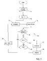
- FIG. 7 is a process flow of a genetic algorithm used to correctly disambiguating between shooter trajectories.
- FIG. 8 is a process flow for discriminating against non-shockwave signals.
- the invention is directed, inter alia, to a system and method for determining the direction, as defined by azimuth and elevation, of a shooter location and a trajectory of supersonic projectiles based on shockwave-only information.
- Supersonic projectile trajectories are estimated solely from projectile shockwave arrival times measured by several closely spaced sensors distributed throughout a “small” measurement volume referred to as antenna.
- a measurement volume is considered small if the sensor spacing is 2 meters or less.
- the shockwave surface is considered to be an expanding conical surface having its axis coincident with the bullet trajectory.
- the shockwave surface is also referred to as the Mach cone.
- three properties, the arrival angle, the radius of curvature, and the spatial gradient of the radius of curvature of the expanding conical surface are to be determined from arrival times measured at five or more antenna sensors.
- the arrival angle of the conical surface-generator that first reaches the antenna determines two possible relative angles (often called ‘ambiguous’ angles) of the bullet trajectory relative to the arrival angle at the antenna.
- the ‘ambiguous’ angles will be described in more detail below with reference to FIG. 3 .
- the radius of curvature of the conical surface at the antenna determines both distance and direction to the trajectory.
- the gradient of the radius of curvature along the path of the surface-generator determines which direction the bullet is moving, thereby removing the ‘ambiguity’ between the two possible directions. Determining these three shockwave properties accurately and correctly decide between the two possible ‘ambiguous’ trajectory angles requires very precise measurements. For example, random errors should be no greater than approximately 1 ⁇ s to decide correctly between the two alternative shooter aspect angles.
- the time instant that the first sensor, designated as the reference sensor, detects the advancing conical surface is denoted as t o .
- the other sensors detect the advancing conical surface at subsequent times denoted as t i .
- the system advantageously incorporates features to ensure that it will not mistake non-ballistic signals, such as vehicle noise, vibration, wind-noise and EMI, for a shooter.
- the sensor mast can be mounted to a vehicle (not shown) with elastomeric sleeves in mating joints to prevent rattling.
- the sensors can be attached to the ends of the spines with elastomeric couplings, having low-frequency resonances at about 1 Hz to isolate them from spine vibration.
- Sensor spines can be attached to a common hub that contains analog electronics, which can also be attached to the sensor mast with elastomeric shock mounts to isolate it from mast vibrations.
- the following decision algorithm can be employed to filter out signals that lack the signatures typically found in shockwave-derived signals. All the values are parameterized, i.e., relative, and can be tuned externally. The listed values are provided only for illustration.
- a process 800 determines if a detected signal originates from a shockwave.
- the process 800 starts at step 802 and checks in step 804 if the signal is a loud enough event to count as a shock, for example, does the peak signal value exceed a given parameterized threshold of, e.g., 500. If this is the case, the process 800 continues with step 806 and checks if there is a sharp transient from zero to the peak signal value, making sure that the transient to this peak value is not preceded by another signal having a significant magnitude, for example, 1/16 of the peak signal value.
- step 808 checks if the time between shockwave minima and maxima has a sufficiently large value, for example, 200-400 ⁇ s. If this is the case, the process 800 continues with step 810 and checks if the magnitudes of the minima and maxima peak signal amplitudes close, e.g. within 35% of one another. If this is the case, the process 800 continues with step 812 and checks if the pressure peak transient from the minimum peak signal to zero is sharp, using essentially the same criteria as in step 806 .
- step 814 the process 800 continues with step 814 and checks if the times between the maximum signal value and the zero-crossing and between the zero-crossing and the minimum signal value are comparable, for example, within approximately 180 ⁇ s. If all steps produce an affirmative response, the process 800 decides that the signal can be a shockwave and the signal is processed, step 816 . Conversely, if one of the 6 decision steps is answered in the negative, the detected signal does not originate from a shockwave, step 818 .
- the projectile trajectory is assumed to coincide with the x axis.
- L refers to the characteristic length of the antenna.
- the radii of curvature of the cone at the two ends of the antenna 20 are r 1 and r 2 .
- the end view in the left half of the picture shows how curvature r 1 is measured.
- the mean measurement values at the two ends of the array correctly determine the local curvature there.
- Exemplary distributions of measurement values for the time differences dt 1 and dt 2 are shown in FIG. 4 .
- the sample measurement made at end 2 is shown as X.
- the radius of curvature at end 2 (radius r 2 ) is smaller than at end 1 (radius r 1 ). Therefore, all measurements made at end one that have values larger than X will result in the correct decision that curvature at end 1 is greater than at end 2.
- the probability that the correct decision is made when the measurement at end 2 is equal to X is given by:
- Timing errors arise also both from gain and signal strength variations from channel to channel. Times of arrival are obtained when sensor outputs rise to a preset threshold value V 0 .
- the timing error dt caused by a gain variation dg depends upon the time rate of voltage increase for the channel.
- Timing errors also occur when the signal strength varies over the aperture.
- the maximum signal level variation across the aperture is equal to p 0 (L/2r), where p 0 is the sound pressure at the aperture center.
- the amplitude errors are not random among sensors, but vary uniformly from a maximum across the entire aperture to zero at the center. At ranges greater than 10 m, for a 1 m aperture, the maximum amplitude factor is less than 0.05, which is less than the channel gain variation parameter of 0.2, so that effects due to amplitude errors can be ignored. Conversely, as described above, at ranges less than about 10 m the Mach cone radius is small enough with respect to the aperture length of 1 m that measurement errors are not very important.
- the standard deviation of binomially distributed random time sampling errors for a system sampling at 1 MHz is equal to 0.25 ⁇ s. Timing errors due to gain variations are estimated to be approximately 0.75 ⁇ s for an exemplary system with a channel bandwidth of about 18 kHz, corresponding to a voltage rate of about 0.02 V/ ⁇ s.
- the employed acoustic sensors for each array were chosen to have sensitivities within ⁇ 1.5 dB. Therefore, channel relative gain variations are approximately uniformly distributed between 0.84 and 1.19, so that the standard deviation of relative gain is approximately equal to
- Timing error standard deviation can be estimated as
- TDOA Time-Difference-of-Arrival
- the exemplary system uses an analog time difference of arrival (TDOA) circuit using 1 MHz clocks in each channel.
- the clocks are triggered when the sensor signal exceed a threshold signal level at the reference sensor, which was defined above as the sensor that first encounters the shockwave.
- a 1 MHz clock rate is sufficient to eliminate the importance of time-sample errors in practice.
- the system operates in an analog mode, relying on the detection of threshold levels, with the digital logic performing the following functions:
- the correlation for each channel with every other channel is computed, for a time segment centered on the time of the hardware TDOA detection.
- the correlation of two functions, denoted Corr(g, h), is defined by
- G(f) is the Fourier transform of g(t)
- H(f) is the Fourier transform of h(t).
- the total power in a signal is:
- the time-of-arrival signal has a finite length, so that the integration (or summation for discrete data) need only be performed over a finite time interval centered around the time-of-arrival; the length of the data in one or both channels can be extended by zero-padding so that the duration of the two signals matched, as is known in the art.
- the shockwave signal time data g i (t), g j (t) are acquired in each channel i, j, steps 601 , 602 , and recorded as a function of time.
- steps 603 , 604 the total signal power in a channel i is computed for subsequent normalization of the correlation as
- the Fourier transform G i (f) of the shockwave signal time data g i (t) is computed for channel i and the conjugate G i ( ⁇ f) is formed, step 605 .
- the Fourier transform G j (f) of the shockwave signal time data g j (t) is computed for all the other channels j, step 606 .
- the cross-correlation G i ( ⁇ f) ⁇ G j (f) is formed for each channel pair (i, j), step 608 , which is a function f i,j (t) of the “lag” t.
- the TDOA for each channel pair is the time t max where f(t) has its maximum value, step 610 .
- the correlation between the channels i and j can be defined as
- Corr ⁇ ⁇ ( g i , g j ) peak ⁇ ⁇ value ⁇ ⁇ f i , j ⁇ ( t ) ( Power ⁇ ⁇ Channel ⁇ ⁇ i ) * ( Power ⁇ ⁇ Channel ⁇ ⁇ j )
- the residual for channel i is computed by computing the mean value for a sensor i over all sensors j:
- Residual ⁇ ⁇ ( i ) mean ⁇ ⁇ ⁇ j ⁇ i ⁇ ( 1 - Corr ⁇ ⁇ ( g i , g j ) )
- step 612 The TDOAs and correlations for that channel with the best (i.e. smallest) overall residual are then selected as the “best” solution, step 614 .
- the channel data are typically sampled at discrete time intervals with a predefined sampling rate of, for example, 41,666.66 samples/sec. This corresponds to a bin width of 24 ⁇ s, reflecting the time resolution for the received signal.
- the correlation processing is done with a time resolution that is improved by a factor of 8 to 3 ⁇ s by taking 333333 samples/sec.
- the shooter azimuth and elevation and the bullet trajectory can be determined.
- the shooter position i.e. the distance of the shooter from the sensor array can be determined if the muzzle blast signal is known in addition.
- V ( V x V y V z ) represents the supersonic bullet velocity
- the Mach angle ⁇ is defined by
- the true solution for shooter position and bullet trajectory can be obtained by computing the shooter/trajectory combination that minimizes the root-mean-square (RMS) residual of measured and computed shockwave TDOA's:
- ⁇ ⁇ ⁇ ⁇ min min ⁇ ⁇ j ⁇ ( ⁇ calc - ⁇ meas ) 2 ,
- a GA process 70 begins its search by initializing a random population of solutions, step 71 , and sets a generation counter to zero indicating the initial solution set, step 72 .
- a fitness relative merit
- the fitness can be represented by the Euclidean distance ⁇ min between a calculated solution and the measured solution.
- ⁇ ⁇ ⁇ ⁇ min min ⁇ ⁇ j ⁇ ( ⁇ calc - ⁇ meas ) 2
- the exemplary GA uses as a chromosome an initial population of 200 4-s, with each 4-containing the following values: [Azimuth Shooter , Elevation Shooter , Azimuth Missed , Elevation Missed ].
- [Azimuth Shooter , Elevation Shooter ] are defined by the angle ( ⁇ + ⁇ ), while [Azimuth Missed , Elevation Missed ] are defined by the angle ⁇ (see FIG. 3 ). Since muzzle blast is not used with the aforedescribed shockwave-only approach, a nominal range between the sensor array and the shooter of 100 meter is assumed.
- step 75 It is checked in step 75 if a maximum number of iterations for the GA, which can be set, for example, at 25 , has been reached. If the maximum number of iterations has been reached, the process 70 stops at step 80 , and the result can be either accepted or further evaluated. Otherwise, step 76 checks if preset fitness criteria have been satisfied.
- Fitness criteria can be, for example, a computed missed azimuth of ⁇ 15° and/or a ratio of the residuals of two ambiguous solutions. If the fitness criteria are satisfied, the process 70 stops at step 80 ; otherwise, a new population is created through crossover, step 77 , and mutation, step 78 , and the generation counter is incremented by one, step 79 .
- Disambiguation is achieved by performing a gradient search on the best solution and the corresponding alternate solution. For both ambiguous solutions, the residuals and the ratios of the residuals are computed. If the computed missed azimuth is ⁇ 15°, representing “close” shots and if the ratio of the residuals is >2, then the solution with the lower residual is selected. Otherwise, no actual selection is made, and the solution with the lower residual is labeled the “primary” solution, while the other solution is labeled an “alternate” solution.
- the GA algorithm produced a solution on a 1 GHz computer running the Linux operating system in 0.15 seconds on a broad range of simulated shots. 97% of the simulated shots were within 15° of missed azimuth, and 86% of the simulated shots were within 5° of missed azimuth. Using the aforedescribed disambiguation algorithm, close shots, i.e. shots having a missed azimuth of ⁇ 15°, were disambiguated 95% of the time. The disambiguation algorithm produced correct results for more distant shots 70% of the time. The accuracy of disambiguation is expected to vary based on the sensor array geometry and the presumed distribution of shots, with shots having a low elevation being easier to disambiguate.
- the described system can accurately, quickly and often unambiguously provide shooter direction and bullet trajectory based on shockwave-only measurements.
- the system also obtains accurate shooter azimuth solutions when the muzzle blast waveform is detected.
- the system does not give false shooter indications in response to vehicle vibration and noise, nor wind noise, firecrackers or nearby shooting in directions away from the system.
- the system detecting the shockwave signals performs two test on the initial waveforms for determining if the signal can indeed be attributed to shockwaves.
- the measured total energy in a frequency band between approximately 700 Hz and 10 kHz is compared with an empirical threshold value. Only if this threshold value is exceeded, can the signal form be considered as arising from a shockwave.
- the time span of the detected initial positive pressure peak must be greater than approximately 70 ⁇ s and less than approximately 300 ⁇ s. These criteria provide immunity of the system from impulsive noise, such as firecrackers and non-threatening gunfire. If these tests are not passed, the detected waveform is not considered a shockwave, and no shooter solution is attempted.
Abstract
Description
Integration over x and making substitution of variables results in the following probability of making the correct decision:
replacing the relative gain variation
The amplitude errors are not random among sensors, but vary uniformly from a maximum across the entire aperture to zero at the center. At ranges greater than 10 m, for a 1 m aperture, the maximum amplitude factor is less than 0.05, which is less than the channel gain variation parameter of 0.2, so that effects due to amplitude errors can be ignored. Conversely, as described above, at ranges less than about 10 m the Mach cone radius is small enough with respect to the aperture length of 1 m that measurement errors are not very important.
The standard deviation of binomially distributed random time sampling errors for a system sampling at 1 MHz is equal to 0.25 μs. Timing errors due to gain variations are estimated to be approximately 0.75 μs for an exemplary system with a channel bandwidth of about 18 kHz, corresponding to a voltage rate of about 0.02 V/μs. The employed acoustic sensors for each array were chosen to have sensitivities within ±1.5 dB. Therefore, channel relative gain variations are approximately uniformly distributed between 0.84 and 1.19, so that the standard deviation of relative gain is approximately equal to
The threshold voltage is V0=0.15 V, resulting in a standard deviation of timing errors of about 0.75 μs.
-
- 1. A first latch is set when the channel signal amplitude at the reference sensor that first encounters the shockwave crosses a threshold value.
- 2. The first latch sets start counters for each channel, which are incremented by one count at each clock cycle. The processor is alerted.
- 3. The counter in each channel runs until the corresponding sensor encounters the shockwave. This sets a second latch in the channel, which stops the count in that channel. If no second latch is set, the corresponding counter runs to an upper limit value.
- 4. The final number of counts in each counter is recorded in a digital TDOA register.
- 5. The processor reads the TDOA register.
- 6. The processor resets the counters for receiving the next shockwave.
Corr(g,h)
represents the supersonic bullet velocity
with c being the speed of sound and M the Mach number. β represents the ‘miss angle’ between shooter position and bullet trajectory, which includes both azimuth and elevation angles. A direct hit would correspond to β=0. The Mach angle Θ is defined by
[AzimuthShooter, ElevationShooter, AzimuthMissed, ElevationMissed].
AzimuthShooter={0, . . ., 360},
ElevationShooter={−10, . . . , 30},
AzimuthMissed={−20, . . . , 20}, and
ElevationMissed={−20, . . . , 20}.
| TABLE 1 | |||
| Operator | Proba- | ||
| Operator Name | Type | bility | Description |
| Azimuth-Crossover | Crossover | 0.5 | Exchange shooter/trajectory |
| azimuth between two | |||
| chromosomes | |||
| Missed-Crossover | Crossover | 0.5 | Exchange missed azimuth/ |
| elevation between two | |||
| chromosomes | |||
| Field-Mutation | Mutation | 0.3 | Replace a given field (with |
| a probability of 0.25 per | |||
| field) with a randomly | |||
| selected new value within | |||
| range | |||
| Incremental- | Mutation | 0.4 | Introduce small mutations in |
| Mutation | all fields of a chromosome | ||
| (within ≦ 2° for shooter | |||
| information; within ≦ 0.5° | |||
| for missed information | |||
| Flip-Mutation | Mutation | 0.1 | Change the solution into the |
| ambiguous alternate solution | |||
| No-Mutation | Mutation | 0.2 | Chromosome remains intact |
Claims (20)
Priority Applications (1)
| Application Number | Priority Date | Filing Date | Title |
|---|---|---|---|
| US11/580,804 US7408840B2 (en) | 2004-08-24 | 2006-10-13 | System and method for disambiguating shooter locations |
Applications Claiming Priority (2)
| Application Number | Priority Date | Filing Date | Title |
|---|---|---|---|
| US10/925,875 US7126877B2 (en) | 2004-08-24 | 2004-08-24 | System and method for disambiguating shooter locations |
| US11/580,804 US7408840B2 (en) | 2004-08-24 | 2006-10-13 | System and method for disambiguating shooter locations |
Related Parent Applications (1)
| Application Number | Title | Priority Date | Filing Date |
|---|---|---|---|
| US10/925,875 Division US7126877B2 (en) | 2004-08-24 | 2004-08-24 | System and method for disambiguating shooter locations |
Publications (2)
| Publication Number | Publication Date |
|---|---|
| US20070030763A1 US20070030763A1 (en) | 2007-02-08 |
| US7408840B2 true US7408840B2 (en) | 2008-08-05 |
Family
ID=35942874
Family Applications (2)
| Application Number | Title | Priority Date | Filing Date |
|---|---|---|---|
| US10/925,875 Active 2025-02-22 US7126877B2 (en) | 2004-08-24 | 2004-08-24 | System and method for disambiguating shooter locations |
| US11/580,804 Active 2024-09-30 US7408840B2 (en) | 2004-08-24 | 2006-10-13 | System and method for disambiguating shooter locations |
Family Applications Before (1)
| Application Number | Title | Priority Date | Filing Date |
|---|---|---|---|
| US10/925,875 Active 2025-02-22 US7126877B2 (en) | 2004-08-24 | 2004-08-24 | System and method for disambiguating shooter locations |
Country Status (2)
| Country | Link |
|---|---|
| US (2) | US7126877B2 (en) |
| ES (1) | ES2351677T3 (en) |
Cited By (12)
| Publication number | Priority date | Publication date | Assignee | Title |
|---|---|---|---|---|
| US20070042706A1 (en) * | 2005-04-08 | 2007-02-22 | Vanderbilt University | System and methods of radio interference based localization in sensor networks |
| US20080159078A1 (en) * | 2005-08-23 | 2008-07-03 | Bbn Technologies Corp | Systems and methods for determining shooter locations with weak muzzle detection |
| US20100020643A1 (en) * | 2008-07-28 | 2010-01-28 | Bbn Technologies Corp. | System and methods for detecting shooter locations from an aircraft |
| US20100142328A1 (en) * | 2008-12-05 | 2010-06-10 | Steven David Beck | Projectile-Detection Collars and Methods |
| US8149649B1 (en) | 2004-08-24 | 2012-04-03 | Raytheon Bbn Technologies Corp. | Self calibrating shooter estimation |
| US8320217B1 (en) | 2009-10-01 | 2012-11-27 | Raytheon Bbn Technologies Corp. | Systems and methods for disambiguating shooter locations with shockwave-only location |
| US8515126B1 (en) | 2007-05-03 | 2013-08-20 | Hrl Laboratories, Llc | Multi-stage method for object detection using cognitive swarms and system for automated response to detected objects |
| US8649565B1 (en) | 2009-06-18 | 2014-02-11 | Hrl Laboratories, Llc | System for automatic object localization based on visual simultaneous localization and mapping (SLAM) and cognitive swarm recognition |
| US8965044B1 (en) | 2009-06-18 | 2015-02-24 | The Boeing Company | Rotorcraft threat detection system |
| US10054576B2 (en) | 2014-08-29 | 2018-08-21 | Tracer Technology Systems Inc. | System and device for nearfield gunshot and explosion detection |
| EP3514478A1 (en) | 2017-12-26 | 2019-07-24 | Aselsan Elektronik Sanayi ve Ticaret Anonim Sirketi | A method for acoustic detection of shooter location |
| US11693103B2 (en) | 2020-04-17 | 2023-07-04 | Aselsan Elektronik San. Ve Tic. A. S. | Shooting range estimation method based on miss distance and weapon caliber prediction for firearms |
Families Citing this family (20)
| Publication number | Priority date | Publication date | Assignee | Title |
|---|---|---|---|---|
| JP2008281552A (en) * | 2007-04-09 | 2008-11-20 | Seiko Epson Corp | Method and program for calculating and determining first located output position, storage medium, positioning device, and electronic equipment |
| GB0722169D0 (en) * | 2007-11-12 | 2008-10-08 | Selex Sensors & Airborne Sys | Method and apparatus for detecting a launch postion of a projectile |
| US7787331B2 (en) | 2008-05-13 | 2010-08-31 | Bbn Technologies, Corp. | Sensor for airborne shooter localization system |
| US8009515B2 (en) | 2008-12-01 | 2011-08-30 | Lockheed Martin Corporation | Ground threat location for an aircraft |
| US8194501B2 (en) * | 2009-11-24 | 2012-06-05 | The United States Of America As Represented By The Secretary Of The Army | Apparatus and method of sniper localization |
| US8408115B2 (en) | 2010-09-20 | 2013-04-02 | Raytheon Bbn Technologies Corp. | Systems and methods for an indicator for a weapon sight |
| US8817577B2 (en) | 2011-05-26 | 2014-08-26 | Mahmood R. Azimi-Sadjadi | Gunshot locating system and method |
| US20130107668A1 (en) | 2011-10-28 | 2013-05-02 | Raytheon Company | Convoy-based systems and methods for locating an acoustic source |
| US8555726B2 (en) * | 2011-12-23 | 2013-10-15 | Raytheon BBN Technology Corp. | Acoustic sensors for detecting shooter locations from an aircraft |
| US9714815B2 (en) | 2012-06-19 | 2017-07-25 | Lockheed Martin Corporation | Visual disruption network and system, method, and computer program product thereof |
| US9632168B2 (en) | 2012-06-19 | 2017-04-25 | Lockheed Martin Corporation | Visual disruption system, method, and computer program product |
| US9103628B1 (en) | 2013-03-14 | 2015-08-11 | Lockheed Martin Corporation | System, method, and computer program product for hostile fire strike indication |
| US9146251B2 (en) | 2013-03-14 | 2015-09-29 | Lockheed Martin Corporation | System, method, and computer program product for indicating hostile fire |
| US9196041B2 (en) | 2013-03-14 | 2015-11-24 | Lockheed Martin Corporation | System, method, and computer program product for indicating hostile fire |
| US9910128B2 (en) | 2015-03-26 | 2018-03-06 | Databuoy Corporation | Acoustic source localization in confined spaces |
| CN105486452B (en) * | 2015-12-31 | 2018-11-13 | 张宇峰 | Shock wave tests comparison-type scaling method |
| RU2670731C9 (en) * | 2016-01-11 | 2018-11-30 | Федеральное государственное казенное военное образовательное учреждение высшего профессионального образования "Пермский военный институт внутренних войск Министерства внутренних дел Российской Федерации" | Method for determining supersonic projectile flight trajectory |
| EP3236209B1 (en) * | 2016-04-19 | 2021-06-09 | Honda Research Institute Europe GmbH | Navigation system and method for error correction |
| GB2575830B (en) * | 2018-07-24 | 2022-04-13 | Thales Holdings Uk Plc | Wake and shockwave gunshot detection |
| WO2020236607A1 (en) | 2019-05-18 | 2020-11-26 | Battelle Memorial Institute | Firearm discharge location systems and methods |
Citations (34)
| Publication number | Priority date | Publication date | Assignee | Title |
|---|---|---|---|---|
| GB2015127A (en) | 1978-01-06 | 1979-09-05 | Australasian Training Aids Pty | Improvements in or Relating to Target Apparatus |
| US4827411A (en) | 1987-06-15 | 1989-05-02 | International Business Machines Corporation | Method of maintaining a topology database |
| US4970698A (en) | 1988-06-27 | 1990-11-13 | Dumestre Iii Alex C | Self-calibrating sonar system |
| EP0447725A2 (en) | 1990-03-21 | 1991-09-25 | Digital Equipment Corporation | Updating link state information in networks |
| US5093824A (en) | 1990-03-27 | 1992-03-03 | Bell Communications Research, Inc. | Distributed protocol for improving the survivability of telecommunications trunk networks |
| US5241518A (en) | 1992-02-18 | 1993-08-31 | Aai Corporation | Methods and apparatus for determining the trajectory of a supersonic projectile |
| US5243592A (en) | 1990-10-15 | 1993-09-07 | Digital Equipment Corporation | Method and apparatus for distance vector routing on datagram point-to-point links |
| US5280457A (en) | 1992-07-31 | 1994-01-18 | The Administrators Of The Tulane Educational Fund | Position detecting system and method |
| US5346210A (en) | 1992-08-28 | 1994-09-13 | Teem Systems, Inc. | Object locator system |
| US5544129A (en) | 1994-08-30 | 1996-08-06 | Aai Corporation | Method and apparatus for determining the general direction of the origin of a projectile |
| US5742820A (en) | 1995-07-06 | 1998-04-21 | Novell, Inc. | Mechanism for efficiently synchronizing information over a network |
| US5777948A (en) | 1996-11-12 | 1998-07-07 | The United States Of America As Represented By The Secretary Of The Navy | Method and apparatus for preforming mutations in a genetic algorithm-based underwater target tracking system |
| US5781505A (en) | 1997-10-14 | 1998-07-14 | The United States Of America As Represented By The Secretary Of The Navy | System and method for locating a trajectory and a source of a projectile |
| US5850592A (en) | 1996-01-11 | 1998-12-15 | Gte Internetworking Incorporated | Method for self-organizing mobile wireless station network |
| US5878095A (en) | 1994-03-01 | 1999-03-02 | Nokia Telecommunications Oy | Hierarchical synchronization method |
| US5881246A (en) | 1996-06-12 | 1999-03-09 | Bay Networks, Inc. | System for generating explicit routing advertisements to specify a selected path through a connectionless network to a destination by a specific router |
| US5912862A (en) | 1995-09-26 | 1999-06-15 | Gustavsen; Arve | Automatic determination of sniper position from a stationary or mobile platform |
| US5913921A (en) | 1996-07-12 | 1999-06-22 | Glenayre Electronics, Inc. | System for communicating information about nodes configuration by generating advertisements having era values for identifying time reference for which the configuration is operative |
| US5930202A (en) | 1996-11-20 | 1999-07-27 | Gte Internetworking Incorporated | Acoustic counter-sniper system |
| US5973998A (en) | 1997-08-01 | 1999-10-26 | Trilon Technology, Llc. | Automatic real-time gunshot locator and display system |
| US6055523A (en) | 1997-07-15 | 2000-04-25 | The United States Of America As Represented By The Secretary Of The Army | Method and apparatus for multi-sensor, multi-target tracking using a genetic algorithm |
| US6088622A (en) | 1997-01-13 | 2000-07-11 | Hewlett-Packard Company | Report stream data rate regulation |
| US6178141B1 (en) | 1996-11-20 | 2001-01-23 | Gte Internetworking Incorporated | Acoustic counter-sniper system |
| US6198694B1 (en) | 1996-03-29 | 2001-03-06 | Håkan Appelgren | Method and device for projectile measurements |
| WO2001037483A2 (en) | 1999-11-12 | 2001-05-25 | Itt Manufacturing Enterprises, Inc. | Method and apparatus for transmission of node link status messages |
| US6349091B1 (en) | 1999-11-12 | 2002-02-19 | Itt Manufacturing Enterprises, Inc. | Method and apparatus for controlling communication links between network nodes to reduce communication protocol overhead traffic |
| US20020029214A1 (en) | 2000-08-10 | 2002-03-07 | Nec Corporation | Synchronizable transactional database method and system |
| WO2002082097A2 (en) | 2001-04-03 | 2002-10-17 | Aai Corporation | Method and system for correcting for curvature in determining the trajectory of a projectile |
| US6470329B1 (en) | 2000-07-11 | 2002-10-22 | Sun Microsystems, Inc. | One-way hash functions for distributed data synchronization |
| US6487516B1 (en) | 1998-10-29 | 2002-11-26 | Netmor Ltd. | System for three dimensional positioning and tracking with dynamic range extension |
| US20040100868A1 (en) | 2002-08-07 | 2004-05-27 | Frank Patterson | System and method for identifying and locating an acoustic event |
| US6745224B1 (en) | 1996-12-06 | 2004-06-01 | Microsoft Corporation | Object framework and services for periodically recurring operations |
| US20060256660A1 (en) | 2005-04-07 | 2006-11-16 | Berger Theodore W | Real time acoustic event location and classification system with camera display |
| US7139222B1 (en) | 2004-01-20 | 2006-11-21 | Kevin Baxter | System and method for protecting the location of an acoustic event detector |
Family Cites Families (1)
| Publication number | Priority date | Publication date | Assignee | Title |
|---|---|---|---|---|
| JPH1196002A (en) * | 1997-09-18 | 1999-04-09 | Sanyo Electric Co Ltd | Data processor |
-
2004
- 2004-08-24 US US10/925,875 patent/US7126877B2/en active Active
-
2005
- 2005-08-24 ES ES08004009T patent/ES2351677T3/en active Active
-
2006
- 2006-10-13 US US11/580,804 patent/US7408840B2/en active Active
Patent Citations (38)
| Publication number | Priority date | Publication date | Assignee | Title |
|---|---|---|---|---|
| GB2015127A (en) | 1978-01-06 | 1979-09-05 | Australasian Training Aids Pty | Improvements in or Relating to Target Apparatus |
| US4827411A (en) | 1987-06-15 | 1989-05-02 | International Business Machines Corporation | Method of maintaining a topology database |
| US4970698A (en) | 1988-06-27 | 1990-11-13 | Dumestre Iii Alex C | Self-calibrating sonar system |
| EP0447725A2 (en) | 1990-03-21 | 1991-09-25 | Digital Equipment Corporation | Updating link state information in networks |
| US5093824A (en) | 1990-03-27 | 1992-03-03 | Bell Communications Research, Inc. | Distributed protocol for improving the survivability of telecommunications trunk networks |
| US5243592A (en) | 1990-10-15 | 1993-09-07 | Digital Equipment Corporation | Method and apparatus for distance vector routing on datagram point-to-point links |
| US5241518A (en) | 1992-02-18 | 1993-08-31 | Aai Corporation | Methods and apparatus for determining the trajectory of a supersonic projectile |
| US5280457A (en) | 1992-07-31 | 1994-01-18 | The Administrators Of The Tulane Educational Fund | Position detecting system and method |
| US5346210A (en) | 1992-08-28 | 1994-09-13 | Teem Systems, Inc. | Object locator system |
| US5878095A (en) | 1994-03-01 | 1999-03-02 | Nokia Telecommunications Oy | Hierarchical synchronization method |
| US5544129A (en) | 1994-08-30 | 1996-08-06 | Aai Corporation | Method and apparatus for determining the general direction of the origin of a projectile |
| US5742820A (en) | 1995-07-06 | 1998-04-21 | Novell, Inc. | Mechanism for efficiently synchronizing information over a network |
| US5912862A (en) | 1995-09-26 | 1999-06-15 | Gustavsen; Arve | Automatic determination of sniper position from a stationary or mobile platform |
| US6418299B1 (en) | 1996-01-11 | 2002-07-09 | Bbn Corporation | Self-organizing mobile wireless station network |
| US5850592A (en) | 1996-01-11 | 1998-12-15 | Gte Internetworking Incorporated | Method for self-organizing mobile wireless station network |
| US6198694B1 (en) | 1996-03-29 | 2001-03-06 | Håkan Appelgren | Method and device for projectile measurements |
| US5881246A (en) | 1996-06-12 | 1999-03-09 | Bay Networks, Inc. | System for generating explicit routing advertisements to specify a selected path through a connectionless network to a destination by a specific router |
| US5913921A (en) | 1996-07-12 | 1999-06-22 | Glenayre Electronics, Inc. | System for communicating information about nodes configuration by generating advertisements having era values for identifying time reference for which the configuration is operative |
| US5777948A (en) | 1996-11-12 | 1998-07-07 | The United States Of America As Represented By The Secretary Of The Navy | Method and apparatus for preforming mutations in a genetic algorithm-based underwater target tracking system |
| US5930202A (en) | 1996-11-20 | 1999-07-27 | Gte Internetworking Incorporated | Acoustic counter-sniper system |
| US6178141B1 (en) | 1996-11-20 | 2001-01-23 | Gte Internetworking Incorporated | Acoustic counter-sniper system |
| US6745224B1 (en) | 1996-12-06 | 2004-06-01 | Microsoft Corporation | Object framework and services for periodically recurring operations |
| US6088622A (en) | 1997-01-13 | 2000-07-11 | Hewlett-Packard Company | Report stream data rate regulation |
| US6055523A (en) | 1997-07-15 | 2000-04-25 | The United States Of America As Represented By The Secretary Of The Army | Method and apparatus for multi-sensor, multi-target tracking using a genetic algorithm |
| US5973998A (en) | 1997-08-01 | 1999-10-26 | Trilon Technology, Llc. | Automatic real-time gunshot locator and display system |
| US5781505A (en) | 1997-10-14 | 1998-07-14 | The United States Of America As Represented By The Secretary Of The Navy | System and method for locating a trajectory and a source of a projectile |
| US6487516B1 (en) | 1998-10-29 | 2002-11-26 | Netmor Ltd. | System for three dimensional positioning and tracking with dynamic range extension |
| WO2001037483A2 (en) | 1999-11-12 | 2001-05-25 | Itt Manufacturing Enterprises, Inc. | Method and apparatus for transmission of node link status messages |
| US6385174B1 (en) | 1999-11-12 | 2002-05-07 | Itt Manufacturing Enterprises, Inc. | Method and apparatus for transmission of node link status messages throughout a network with reduced communication protocol overhead traffic |
| US6349091B1 (en) | 1999-11-12 | 2002-02-19 | Itt Manufacturing Enterprises, Inc. | Method and apparatus for controlling communication links between network nodes to reduce communication protocol overhead traffic |
| US6470329B1 (en) | 2000-07-11 | 2002-10-22 | Sun Microsystems, Inc. | One-way hash functions for distributed data synchronization |
| US20020029214A1 (en) | 2000-08-10 | 2002-03-07 | Nec Corporation | Synchronizable transactional database method and system |
| WO2002082097A2 (en) | 2001-04-03 | 2002-10-17 | Aai Corporation | Method and system for correcting for curvature in determining the trajectory of a projectile |
| US6563763B2 (en) * | 2001-04-03 | 2003-05-13 | Aai Corporation | Method and system for correcting for curvature in determining the trajectory of a projectile |
| US20040100868A1 (en) | 2002-08-07 | 2004-05-27 | Frank Patterson | System and method for identifying and locating an acoustic event |
| US6847587B2 (en) | 2002-08-07 | 2005-01-25 | Frank K. Patterson | System and method for identifying and locating an acoustic event |
| US7139222B1 (en) | 2004-01-20 | 2006-11-21 | Kevin Baxter | System and method for protecting the location of an acoustic event detector |
| US20060256660A1 (en) | 2005-04-07 | 2006-11-16 | Berger Theodore W | Real time acoustic event location and classification system with camera display |
Non-Patent Citations (15)
| Title |
|---|
| "Analysis of Routing Strategies for Packet Radio Networks," J.J. Garcia Lune Aceves et al., Proc. of the IEEE INFOCOM '85, Washington, DC, 292-302 (185). |
| "Link-State Routing," John Moy, Ch. 5, "Routing in Communications Networks," ed. Martha Steenstrup, Prentice Hall, pp. 136-157 (1995). |
| "Packet Radio Network Routing Algorithms: A Survey," J.J. Hahn et al., IEEE Communications Magazine, 22:11, 41-7 (Nov. 1984). |
| "Packet Radio Routing," Gregory S. Lauer, Ch. 11, "Routing in Communications Networks," ed. Martha Steenstrup, Prentice Hall, pp. 352-396 (1995). |
| "The DARPA Packet Radio Network Protocols," J. Jubin et al., Proc. of the IEEE, 75:1, 21-32 (Jan. 1987). |
| "The Organization of Computer Resources into a Packet Radio Network," R.E. Kahn, IEEE Trans. on Communications. COM-25:1, 169-78 (Jan. 1977). |
| Danicki, "The shock wave-based acoustic sniper localization," Nonlinear Analysis, 65 (2006), pp. 956-962. |
| Kalyanmoy Deb, "Multi-Objective Optimization Using Evolutionary Algorithms," John Wiley & Sons, Ltd., (2001), pp. 85-101. |
| Ledeczi et al, "Multiple Simultaneous Acoustic Source Localization in Urban Terrain," Institute for Software Integrated Systems, pp. 491-496, ISBN# 0-7803-9201-9 or Information Processing in Sensor Networks, 2005, IPSN 2005. Fourth International Symposium on Publication Date: Apr. 15, 2005. On pp. 491-496, ISBN: 0-7803-9201-9 Inspect Accession No. 8613383 Digital Object Identifier 10.1109/IPSN.2005.1440982. |
| Maroti et al., "Shooter Localization in Urban Terrain", Computer, 37:8, Aug. 2004, pp. 60-61. |
| Pecina, J.N., "Unmanned Navigation with a Novel Laser and a Smart Software," Aerospace Conference, 2003. Proceedings. 2003 IEEE, vol. 1, Mar. 8-15, 2003 pp. 305-312. |
| Pierce, Allan D., "Nonlinear Effects in Sound Propagation," Acoustics, McGraw-Hill Book Company, 1981, pp. 611-614. |
| U.S. Appl. No. 09/546,052, filed Apr. 10, 2000; Joseph Jacob Weinstein et al.; Radio Network Routing Apparatus; 31 pages. Under examination by Toan D. Nguyen. |
| U.S. Appl. No. 10/752,988, filed Jan. 7, 2004; Joseph Jacob Weinstein et al; Systems and Methods for Constructing a Virtual Model of a Multi-Hop, Multi-Access Network; 81 pages. |
| U.S. Appl. No. 10/797,030, filed Mar. 11, 2004; Joseph Jacob Weinstein et al.; Systems and Methods for Synchronizing Multiple Copies of a Database Using Database Digest; 49 pages. |
Cited By (17)
| Publication number | Priority date | Publication date | Assignee | Title |
|---|---|---|---|---|
| US8149649B1 (en) | 2004-08-24 | 2012-04-03 | Raytheon Bbn Technologies Corp. | Self calibrating shooter estimation |
| US7558583B2 (en) * | 2005-04-08 | 2009-07-07 | Vanderbilt University | System and methods of radio interference based localization in sensor networks |
| US20070042706A1 (en) * | 2005-04-08 | 2007-02-22 | Vanderbilt University | System and methods of radio interference based localization in sensor networks |
| US20080159078A1 (en) * | 2005-08-23 | 2008-07-03 | Bbn Technologies Corp | Systems and methods for determining shooter locations with weak muzzle detection |
| US7710828B2 (en) | 2005-08-23 | 2010-05-04 | Bbn Technologies Corp | Systems and methods for determining shooter locations with weak muzzle detection |
| US8515126B1 (en) | 2007-05-03 | 2013-08-20 | Hrl Laboratories, Llc | Multi-stage method for object detection using cognitive swarms and system for automated response to detected objects |
| US20100020643A1 (en) * | 2008-07-28 | 2010-01-28 | Bbn Technologies Corp. | System and methods for detecting shooter locations from an aircraft |
| US8437223B2 (en) | 2008-07-28 | 2013-05-07 | Raytheon Bbn Technologies Corp. | System and methods for detecting shooter locations from an aircraft |
| US20100142328A1 (en) * | 2008-12-05 | 2010-06-10 | Steven David Beck | Projectile-Detection Collars and Methods |
| US8111582B2 (en) | 2008-12-05 | 2012-02-07 | Bae Systems Information And Electronic Systems Integration Inc. | Projectile-detection collars and methods |
| US8965044B1 (en) | 2009-06-18 | 2015-02-24 | The Boeing Company | Rotorcraft threat detection system |
| US8649565B1 (en) | 2009-06-18 | 2014-02-11 | Hrl Laboratories, Llc | System for automatic object localization based on visual simultaneous localization and mapping (SLAM) and cognitive swarm recognition |
| US8320217B1 (en) | 2009-10-01 | 2012-11-27 | Raytheon Bbn Technologies Corp. | Systems and methods for disambiguating shooter locations with shockwave-only location |
| US10054576B2 (en) | 2014-08-29 | 2018-08-21 | Tracer Technology Systems Inc. | System and device for nearfield gunshot and explosion detection |
| EP3514478A1 (en) | 2017-12-26 | 2019-07-24 | Aselsan Elektronik Sanayi ve Ticaret Anonim Sirketi | A method for acoustic detection of shooter location |
| US10887698B2 (en) | 2017-12-26 | 2021-01-05 | Aselsan Eletronik Sanayi Ve Ticaret Anonim Sirketi | Method for acoustic detection of shooter location |
| US11693103B2 (en) | 2020-04-17 | 2023-07-04 | Aselsan Elektronik San. Ve Tic. A. S. | Shooting range estimation method based on miss distance and weapon caliber prediction for firearms |
Also Published As
| Publication number | Publication date |
|---|---|
| US20060044943A1 (en) | 2006-03-02 |
| US7126877B2 (en) | 2006-10-24 |
| US20070030763A1 (en) | 2007-02-08 |
| ES2351677T3 (en) | 2011-02-09 |
Similar Documents
| Publication | Publication Date | Title |
|---|---|---|
| US7408840B2 (en) | System and method for disambiguating shooter locations | |
| EP1787138B1 (en) | Systems and methods for disambiguating shooter locations | |
| US8005631B2 (en) | System and method for identifying a muzzle blast using a multi-sensor total energy approach |
Legal Events
| Date | Code | Title | Description |
|---|---|---|---|
| AS | Assignment |
Owner name: BBNT SOLUTIONS LLC, MASSACHUSETTS Free format text: ASSIGNMENT OF ASSIGNORS INTEREST;ASSIGNORS:BARGER, JAMES E.;MILLIGAN, STEPHEN D.;BRINN, MARSHALL SETH;REEL/FRAME:018422/0739;SIGNING DATES FROM 20041119 TO 20041123 Owner name: BANK OF AMERICA, N.A. (SUCCESSOR BY MERGER TO FLEE Free format text: PATENT AND TRADEMARK SECURITY AGREEMENT;ASSIGNOR:BBN TECHNOLOGIES CORP.;REEL/FRAME:018417/0505 Effective date: 20040326 |
|
| AS | Assignment |
Owner name: BBN TECHNOLOGIES CORP., MASSACHUSETTS Free format text: CHANGE OF NAME;ASSIGNOR:BBNT SOLUTIONS LLC;REEL/FRAME:018759/0027 Effective date: 20060103 |
|
| AS | Assignment |
Owner name: BBN TECHNOLOGIES CORP., MASSACHUSETTS Free format text: ASSIGNMENT OF ASSIGNORS INTEREST;ASSIGNOR:MULLEN, RICHARD J.;REEL/FRAME:020587/0346 Effective date: 20070813 |
|
| STCF | Information on status: patent grant |
Free format text: PATENTED CASE |
|
| AS | Assignment |
Owner name: BBN TECHNOLOGIES CORP. (AS SUCCESSOR BY MERGER TO Free format text: RELEASE OF SECURITY INTEREST;ASSIGNOR:BANK OF AMERICA, N.A. (SUCCESSOR BY MERGER TO FLEET NATIONAL BANK);REEL/FRAME:023427/0436 Effective date: 20091026 |
|
| AS | Assignment |
Owner name: RAYTHEON BBN TECHNOLOGIES CORP.,MASSACHUSETTS Free format text: CHANGE OF NAME;ASSIGNOR:BBN TECHNOLOGIES CORP.;REEL/FRAME:024456/0537 Effective date: 20091027 Owner name: RAYTHEON BBN TECHNOLOGIES CORP., MASSACHUSETTS Free format text: CHANGE OF NAME;ASSIGNOR:BBN TECHNOLOGIES CORP.;REEL/FRAME:024456/0537 Effective date: 20091027 |
|
| FEPP | Fee payment procedure |
Free format text: PAYOR NUMBER ASSIGNED (ORIGINAL EVENT CODE: ASPN); ENTITY STATUS OF PATENT OWNER: LARGE ENTITY |
|
| FPAY | Fee payment |
Year of fee payment: 4 |
|
| FPAY | Fee payment |
Year of fee payment: 8 |
|
| MAFP | Maintenance fee payment |
Free format text: PAYMENT OF MAINTENANCE FEE, 12TH YEAR, LARGE ENTITY (ORIGINAL EVENT CODE: M1553); ENTITY STATUS OF PATENT OWNER: LARGE ENTITY Year of fee payment: 12 |