US7399033B2 - Vehicle video display device on armrest - Google Patents
Vehicle video display device on armrest Download PDFInfo
- Publication number
- US7399033B2 US7399033B2 US11/419,510 US41951006A US7399033B2 US 7399033 B2 US7399033 B2 US 7399033B2 US 41951006 A US41951006 A US 41951006A US 7399033 B2 US7399033 B2 US 7399033B2
- Authority
- US
- United States
- Prior art keywords
- display device
- video display
- vehicle video
- arm members
- armrest
- Prior art date
- Legal status (The legal status is an assumption and is not a legal conclusion. Google has not performed a legal analysis and makes no representation as to the accuracy of the status listed.)
- Expired - Fee Related, expires
Links
Images


Classifications
-
- B—PERFORMING OPERATIONS; TRANSPORTING
- B60—VEHICLES IN GENERAL
- B60R—VEHICLES, VEHICLE FITTINGS, OR VEHICLE PARTS, NOT OTHERWISE PROVIDED FOR
- B60R11/00—Arrangements for holding or mounting articles, not otherwise provided for
- B60R11/02—Arrangements for holding or mounting articles, not otherwise provided for for radio sets, television sets, telephones, or the like; Arrangement of controls thereof
- B60R11/0229—Arrangements for holding or mounting articles, not otherwise provided for for radio sets, television sets, telephones, or the like; Arrangement of controls thereof for displays, e.g. cathodic tubes
- B60R11/0235—Arrangements for holding or mounting articles, not otherwise provided for for radio sets, television sets, telephones, or the like; Arrangement of controls thereof for displays, e.g. cathodic tubes of flat type, e.g. LCD
-
- B—PERFORMING OPERATIONS; TRANSPORTING
- B60—VEHICLES IN GENERAL
- B60R—VEHICLES, VEHICLE FITTINGS, OR VEHICLE PARTS, NOT OTHERWISE PROVIDED FOR
- B60R11/00—Arrangements for holding or mounting articles, not otherwise provided for
- B60R2011/0001—Arrangements for holding or mounting articles, not otherwise provided for characterised by position
- B60R2011/0003—Arrangements for holding or mounting articles, not otherwise provided for characterised by position inside the vehicle
- B60R2011/0012—Seats or parts thereof
- B60R2011/0014—Arm-rests
-
- B—PERFORMING OPERATIONS; TRANSPORTING
- B60—VEHICLES IN GENERAL
- B60R—VEHICLES, VEHICLE FITTINGS, OR VEHICLE PARTS, NOT OTHERWISE PROVIDED FOR
- B60R11/00—Arrangements for holding or mounting articles, not otherwise provided for
- B60R2011/0042—Arrangements for holding or mounting articles, not otherwise provided for characterised by mounting means
- B60R2011/008—Adjustable or movable supports
-
- H—ELECTRICITY
- H04—ELECTRIC COMMUNICATION TECHNIQUE
- H04N—PICTORIAL COMMUNICATION, e.g. TELEVISION
- H04N5/00—Details of television systems
- H04N5/64—Constructional details of receivers, e.g. cabinets or dust covers
-
- Y—GENERAL TAGGING OF NEW TECHNOLOGICAL DEVELOPMENTS; GENERAL TAGGING OF CROSS-SECTIONAL TECHNOLOGIES SPANNING OVER SEVERAL SECTIONS OF THE IPC; TECHNICAL SUBJECTS COVERED BY FORMER USPC CROSS-REFERENCE ART COLLECTIONS [XRACs] AND DIGESTS
- Y10—TECHNICAL SUBJECTS COVERED BY FORMER USPC
- Y10S—TECHNICAL SUBJECTS COVERED BY FORMER USPC CROSS-REFERENCE ART COLLECTIONS [XRACs] AND DIGESTS
- Y10S248/00—Supports
- Y10S248/917—Video display screen support
- Y10S248/919—Adjustably orientable video screen support
- Y10S248/921—Plural angular
-
- Y—GENERAL TAGGING OF NEW TECHNOLOGICAL DEVELOPMENTS; GENERAL TAGGING OF CROSS-SECTIONAL TECHNOLOGIES SPANNING OVER SEVERAL SECTIONS OF THE IPC; TECHNICAL SUBJECTS COVERED BY FORMER USPC CROSS-REFERENCE ART COLLECTIONS [XRACs] AND DIGESTS
- Y10—TECHNICAL SUBJECTS COVERED BY FORMER USPC
- Y10S—TECHNICAL SUBJECTS COVERED BY FORMER USPC CROSS-REFERENCE ART COLLECTIONS [XRACs] AND DIGESTS
- Y10S248/00—Supports
- Y10S248/917—Video display screen support
- Y10S248/919—Adjustably orientable video screen support
- Y10S248/922—Angular
- Y10S248/923—Tilting
Definitions
- the present invention generally relates to video display devices, and more particularly to an vehicle video display device installed on the armrest of a vehicle.
- Vehicle video display devices for the presentation of movies, electronic maps, and the images captured by bumper cameras have been widely popular in recent years.
- the vehicle video display device usually contains a miniature LCD screen supported by a base on the dashboard or at the front center of the dashboard.
- the installation of the vehicle video device usually requires some destructive means to the interior of the vehicle, which will also make the vehicle's already limited space even, more crowded.
- the usual location of the vehicle video device is either on the dashboard or in front of the dashboard, which is difficult for the rear-seat passengers to watch.
- the primary purpose of the present invention is to provide an vehicle video display device that can be installed by the owner easily on the armrest between the driver and passenger seats or between the rear seats for the convenient, viewing of the rear-seat passengers.
- two arm members have one of their ends pivotally attached to two opposite surfaces of the armrest so that the two arm members extend outward from the armrest in parallel.
- a beam member has its two ends rotatably joined to the other ends of the two arm members respectively so that the beam member is supported across the armrest.
- a screen member of the vehicle video display device is positioned rotatably on the beam member by an axle.
- the screen member installed as such can be turned towards either one of the rear-seat passengers by the axle.
- the screen member can also be tilted forward or backward by the rotation of the beam member for an appropriate viewing angle. If the video display device is not used, the screen member can be flipped completely downward so as to clear the space on the armrest.
- the height and distance of the screen member to the rear-seat passengers can also be adjusted by the swing of the arm members.
- the beam member can be cut for an appropriate length so as to fit on an armrest of a specific width.
- FIG. 1 is a perspective diagram showing the various components of an vehicle video display device according to an embodiment of the present invention.
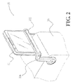
- FIG. 2 is a perspective diagram showing the vehicle video display device of FIG. 2 after its assembly.
- FIG. 3 is an enlarged perspective view the showing the details of the upper joint of an arm member of the vehicle video display device of FIG. 1 .
- FIG. 4 is an enlarged profile view showing the details of the upper joint of an arm member of the vehicle video display device of FIG. 1 .
- FIG. 5 is an enlarged profile view showing the details of the lower joint of an arm member of the vehicle video display device of FIG. 1 .
- FIG. 6 is a profile view of the vehicle video display device of FIG. 1 with the screen member at a normal viewing position.
- FIG. 7 is a profile view of the vehicle video display device of FIG. 1 with the screen member folded.
- FIG. 8 is a perspective view of the vehicle video display device of FIG. 1 with the screen member turned to a side.
- the vehicle video display device 10 As shown in FIGS. 1 and 2 , the vehicle video display device 10 according to an embodiment of the present invention is installed on the armrest 20 between the driver and passenger seats. In the following, all directional or positional references in the specification are made relatively to the armrest 20 .
- the video display device 10 mainly contains two arm members 101 and 102 , and a beam member 103 .
- the arm members 101 and 102 can be housed inside a pair of an outer cover 104 and an inner cover 105 of corresponding shapes, and another pair of an outer cover 104 ′ and an inner cover 105 ′ of corresponding shapes, respectively.
- the arm members 101 and 102 have lower joints 1011 and 1021 at one of their ends pivotally jointed to corresponding locations on two opposite surfaces of the armrest 20 adjacent to the driver and passenger seats respectively. As such, the arm members 101 and 102 extend in parallel outward from the armrest 20 and can be swung around their lower joints 1011 and 1021 respectively.
- the beam member 103 has its two ends rotatably joined to the upper joints 1012 and 1022 at the other ends of the two arm members 101 and 102 respectively so that the beam member 103 is supported across the armrest 20 .
- Each of the upper joints 1012 and 1022 is basically a pin extending perpendicularly from the arm members 101 and 102 and can be embedded inside the connection holes at the two ends of the beam member 103 .
- the upper joint 1012 is rotatably mounted on the arm members 101 and is locked to its corresponding correction hole so that the beam member 103 and the locked upper joint 1012 rotate along with each other.
- it can be the other upper joint 1022 that is locked to the beam member 103 , or both the upper joints 1012 and 1022 are locked to the beam member 103 .
- the upper joint 1012 is used as an example. As shown in FIGS.
- the bottom of the upper joint 1012 has a notch 10121 which provides the entrapment of an elongated lock piece 1013 .
- the lock piece 1013 has one of its ends affixed to the arm member 101 by a bolt 10133 and the lock piece 1013 is therefore flexibly positioned along the inner surface of the arm member 101 .
- the other end of the lock piece 1013 has a tooth 10131 for embedding into the notch 10121 of the upper joint 1012 and a section 10132 bulging through and exposed above the outer surface of the arm member 101 . As such, when the beam member 103 and the upper joint 1012 rotate together, they will be locked at a position when the notch 10121 traps the tooth 10131 .
- a button 1041 can be elastically provided on the outer cover 104 at a location corresponding to the exposed section 10132 . By pressing the button 1041 and in turn driving the exposed section 10132 inward, the tooth 10131 can be easily released.
- the lower joints 1011 and 1021 are identical and in the following the lower joint 1011 is used as an example for explanation.
- the lower joint 1011 and the arm member 101 are pin-joined together to the armrest 20 .
- An interference means 1014 is provided between the lower joint 1011 and the arm member 101 and, with the friction provided by the interference means 1014 , the arm member 101 can be rotated relatively to the lower joint 1011 and held at a specific position.
- the interference means 1014 can be two closely engaged rubber rings (as shown). Ratchet or similar mechanism can also be used.
- the interference means can be provided for at least one of the arm members 101 and 102 . Please also note that instead of using a locking mechanism between at least one of the arm members 101 and 102 and its respective upper joint 1012 or 1022 , similar interference means as described can be used.
- the beam member 103 has a flat surface with scale markings 1033 .
- the scale markings 1033 provide convenient reference when it is required to cut short the beam member 103 to fit on an armrest of a specific width.
- an axle hole 1032 is formed on the flat surface by a removable piece 1031 and the body of the beam member 103 .
- a screen member 11 of the display device 10 has an axle 111 at the center of the bottom rim. The axle 111 can be rotatably mounted in the axle hole 1032 so that the screen member 11 can be swung relatively to the beam member 103 .
- the screen member 11 can be flipped to and locked at an upright position, by the locking mechanism of the upper joint 1012 and the beam member 103 .
- the screen member 11 then is erected vertically and reliably on top of the armrest 20 .
- the height and distance of the screen member 11 to the rear-seat passengers can be adjusted by swing the arm members 101 and 102 (in the diagram only the outer covers 104 is shown) forward or backward.
- the screen member 11 can also be tilted forward or backward by the rotation of the beam member 103 for an appropriate viewing angle (if interference means is used for the upper joints 1012 and/or 1022 ).
- the screen member 11 can be released from the upright position try pressing the button 1041 and flipped completely downward so as to clear the space on the armrest 20 .
- the screen member 11 can be turned towards either one of foe rear-seat passengers for better viewing comfort.
- the armrest 20 is the one between the driver and passenger seats.
- the present invention can actually be installed on the armrest between, the rear seats as well with very little or no modification.
- the present invention can also be installed on the armrest between the passenger seats of a bus, an airplane, or any kind of vehicles.
- the present invention provides a number of advantages over the prior arts. Firstly, the present invention requires only the easy assembly of a few components for a significant redaction of cost. Secondly, the position and angle of the screen member can be flexibly and conveniently adjusted in three degrees of freedom. The screen member can be “folded” so as to occupy minimum space when not in use. In addition, the beam member can be cut to fit on armrests of various sizes.
Landscapes
- Engineering & Computer Science (AREA)
- Mechanical Engineering (AREA)
- Fittings On The Vehicle Exterior For Carrying Loads, And Devices For Holding Or Mounting Articles (AREA)
Abstract
A vehicle video display device is installed on the armrest of a vehicle. Two arm members have one of their ends pivotally attached to two opposite surfaces of the armrest so that the two arm members extend outward from the armrest in parallel. A beam member has its two ends rotatably joined to the other ends of the two arm members respectively so that the beam member is supported across the armrest. A screen member is positioned rotatably on the beam member by an axle.
Description
(a) Technical Field of the Invention
The present invention generally relates to video display devices, and more particularly to an vehicle video display device installed on the armrest of a vehicle.
(b) Description of the Prior Art
Vehicle video display devices for the presentation of movies, electronic maps, and the images captured by bumper cameras have been widely popular in recent years. The vehicle video display device usually contains a miniature LCD screen supported by a base on the dashboard or at the front center of the dashboard.
Unless the vehicle video display device is provider as an integral part of the vehicle system by the car manufacturer, the installation of the vehicle video device usually requires some destructive means to the interior of the vehicle, which will also make the vehicle's already limited space even, more crowded. On the other hand, the usual location of the vehicle video device is either on the dashboard or in front of the dashboard, which is difficult for the rear-seat passengers to watch.
The primary purpose of the present invention is to provide an vehicle video display device that can be installed by the owner easily on the armrest between the driver and passenger seats or between the rear seats for the convenient, viewing of the rear-seat passengers.
According to the present invention, two arm members have one of their ends pivotally attached to two opposite surfaces of the armrest so that the two arm members extend outward from the armrest in parallel. A beam member has its two ends rotatably joined to the other ends of the two arm members respectively so that the beam member is supported across the armrest. A screen member of the vehicle video display device is positioned rotatably on the beam member by an axle.
The screen member installed as such can be turned towards either one of the rear-seat passengers by the axle. The screen member can also be tilted forward or backward by the rotation of the beam member for an appropriate viewing angle. If the video display device is not used, the screen member can be flipped completely downward so as to clear the space on the armrest. The height and distance of the screen member to the rear-seat passengers can also be adjusted by the swing of the arm members. The beam member can be cut for an appropriate length so as to fit on an armrest of a specific width.
The foregoing object and summary provide only a brief introduction to the present invention. To fully appreciate these and other objects of the present invention as well as the invention itself, all of which will become apparent to those skilled in the art, the following detailed description of the invention and the claims should be read in conjunction with the accompanying drawings. Throughout the specification and drawings identical reference numerals refer to identical or similar parts.
Many other advantages and features of the present invention will become manifest to those versed in the art upon making reference to the detailed description and the accompanying sheets of drawings in which a preferred structural embodiment incorporating the principles of the present invention is shown by way of illustrative example.
The following descriptions are of exemplary embodiments only, and are not intended to limit the scope, applicability or configuration of the invention in any way. Rather, the following, description provides a convenient illustration for implementing exemplary embodiments of the invention. Various changes to the described embodiments may be made in the function and arrangement of the elements described without departing from the scope of the invention as set forth in the appended claims.
As shown in FIGS. 1 and 2 , the vehicle video display device 10 according to an embodiment of the present invention is installed on the armrest 20 between the driver and passenger seats. In the following, all directional or positional references in the specification are made relatively to the armrest 20. The video display device 10 mainly contains two arm members 101 and 102, and a beam member 103. The arm members 101 and 102 can be housed inside a pair of an outer cover 104 and an inner cover 105 of corresponding shapes, and another pair of an outer cover 104′ and an inner cover 105′ of corresponding shapes, respectively. The arm members 101 and 102 have lower joints 1011 and 1021 at one of their ends pivotally jointed to corresponding locations on two opposite surfaces of the armrest 20 adjacent to the driver and passenger seats respectively. As such, the arm members 101 and 102 extend in parallel outward from the armrest 20 and can be swung around their lower joints 1011 and 1021 respectively. The beam member 103 has its two ends rotatably joined to the upper joints 1012 and 1022 at the other ends of the two arm members 101 and 102 respectively so that the beam member 103 is supported across the armrest 20.
Each of the upper joints 1012 and 1022 is basically a pin extending perpendicularly from the arm members 101 and 102 and can be embedded inside the connection holes at the two ends of the beam member 103. The upper joint 1012 is rotatably mounted on the arm members 101 and is locked to its corresponding correction hole so that the beam member 103 and the locked upper joint 1012 rotate along with each other. Please note that in alternative embodiments, it can be the other upper joint 1022 that is locked to the beam member 103, or both the upper joints 1012 and 1022 are locked to the beam member 103. For simplicity, in the following the upper joint 1012 is used as an example. As shown in FIGS. 3 and 4 , the bottom of the upper joint 1012 has a notch 10121 which provides the entrapment of an elongated lock piece 1013. The lock piece 1013 has one of its ends affixed to the arm member 101 by a bolt 10133 and the lock piece 1013 is therefore flexibly positioned along the inner surface of the arm member 101. The other end of the lock piece 1013 has a tooth 10131 for embedding into the notch 10121 of the upper joint 1012 and a section 10132 bulging through and exposed above the outer surface of the arm member 101. As such, when the beam member 103 and the upper joint 1012 rotate together, they will be locked at a position when the notch 10121 traps the tooth 10131. Then, by exerting pressure on the exposed section 10132 from the outer surface of the arm member 101, the entrapment of the tooth 10131 is released and the beam member 103 along with the upper joint 1012 can freely rotate again. To facilitate the release of the room 10131, a button 1041 can be elastically provided on the outer cover 104 at a location corresponding to the exposed section 10132. By pressing the button 1041 and in turn driving the exposed section 10132 inward, the tooth 10131 can be easily released.
The lower joints 1011 and 1021 are identical and in the following the lower joint 1011 is used as an example for explanation. The lower joint 1011 and the arm member 101 are pin-joined together to the armrest 20. An interference means 1014 is provided between the lower joint 1011 and the arm member 101 and, with the friction provided by the interference means 1014, the arm member 101 can be rotated relatively to the lower joint 1011 and held at a specific position. The interference means 1014 can be two closely engaged rubber rings (as shown). Ratchet or similar mechanism can also be used. The interference means can be provided for at least one of the arm members 101 and 102. Please also note that instead of using a locking mechanism between at least one of the arm members 101 and 102 and its respective upper joint 1012 or 1022, similar interference means as described can be used.
As shown in FIG. 1 , the beam member 103 has a flat surface with scale markings 1033. The scale markings 1033 provide convenient reference when it is required to cut short the beam member 103 to fit on an armrest of a specific width. In the middle section of the beam member 103, an axle hole 1032 is formed on the flat surface by a removable piece 1031 and the body of the beam member 103. A screen member 11 of the display device 10 has an axle 111 at the center of the bottom rim. The axle 111 can be rotatably mounted in the axle hole 1032 so that the screen member 11 can be swung relatively to the beam member 103.
As shown in FIG. 6 , after the display device 10's assembly, the screen member 11 can be flipped to and locked at an upright position, by the locking mechanism of the upper joint 1012 and the beam member 103. The screen member 11 then is erected vertically and reliably on top of the armrest 20. The height and distance of the screen member 11 to the rear-seat passengers can be adjusted by swing the arm members 101 and 102 (in the diagram only the outer covers 104 is shown) forward or backward. The screen member 11 can also be tilted forward or backward by the rotation of the beam member 103 for an appropriate viewing angle (if interference means is used for the upper joints 1012 and/or 1022).
As shown in FIG. 7 , if the video display device is not used, the screen member 11 can be released from the upright position try pressing the button 1041 and flipped completely downward so as to clear the space on the armrest 20. As shown in FIG. 8 , by the axle 111, the screen member 11 can be turned towards either one of foe rear-seat passengers for better viewing comfort.
Please note that, in the foregoing description, it is assumed that the armrest 20 is the one between the driver and passenger seats. The present invention can actually be installed on the armrest between, the rear seats as well with very little or no modification. Similarly, the present invention can also be installed on the armrest between the passenger seats of a bus, an airplane, or any kind of vehicles.
The present invention provides a number of advantages over the prior arts. Firstly, the present invention requires only the easy assembly of a few components for a significant redaction of cost. Secondly, the position and angle of the screen member can be flexibly and conveniently adjusted in three degrees of freedom. The screen member can be “folded” so as to occupy minimum space when not in use. In addition, the beam member can be cut to fit on armrests of various sizes.
It will be understood that each of the elements described above, or two or more together may also find a useful application in other types of methods differing from the type described above.
While certain novel features of this invention have been shown and described and are pointed out in the annexed claim, it is not intended to be limited to the details above, since it will be understood that various omissions, modifications, substitutions and changes in the forms and details of the device illustrated and in its operation can be made by those skilled in the art without departing in any way from the spirit of the present invention.
Claims (11)
1. An vehicle video display device installed on an armrest of a vehicle comprising:
two arm members each having an upper joint and a lower joint at either ends respectively, said lower joints being attached to two opposite surfaces of said armrest respectively so that said arm members extends pivotally outward from said armrest in parallel;
a beam member having its two ends rotatably joined to said upper joints of said arm members respectively so that said beam member is supported across said armrest, said beam member having an axle hole; and
a screen member rotatably mounted on said beam member by an axle extending from the bottom of said screen member to said axle hole of said beam member.
2. The vehicle video display device according to claim 1 , wherein, for at least one of said arm members, said upper joint rotates along with said beam member and has a notch to trap a first end of an elongated lock piece positioned along the inner surface of said arm member whose second end is fixedly bolted to said arm member; and said lock piece has a section adjacent to said first end bulging through and exposed above the outer surface of said arm member.
3. The vehicle video display device according to claim 2 , wherein each of said arm members is enclosed by an outer cover and an inner cover respectively; and a button is provided on a least one of said outer covers at a location corresponding to said section of said lock piece.
4. The vehicle video display device according to claim 1 , wherein, for least one of said arm members, an interference means is provided between said arm member and its respective upper joint.
5. The vehicle video display device according to claim 4 , wherein said interference means comprises engaged rubber rings.
6. The vehicle video display device according to claim 4 , wherein said interference means comprises ratchet means.
7. The vehicle video display device according to claim 1 , wherein, for at least one of said arm members, an interference means is provided between said arm members and its respective lower joint.
8. The vehicle video display device according to claim 7 , wherein said interference means comprises engaged rubber rings.
9. The vehicle video display device according to claim 7 , wherein said interference means comprises ratchet means.
10. The vehicle video display device accenting to claim 1 , wherein each of said arm members is enclosed, by an outer cover and an inner cover respectively.
11. The vehicle display device according to claim 1 , wherein scale markings are provided along the body of said member.
Priority Applications (1)
| Application Number | Priority Date | Filing Date | Title |
|---|---|---|---|
| US11/419,510 US7399033B2 (en) | 2006-05-22 | 2006-05-22 | Vehicle video display device on armrest |
Applications Claiming Priority (1)
| Application Number | Priority Date | Filing Date | Title |
|---|---|---|---|
| US11/419,510 US7399033B2 (en) | 2006-05-22 | 2006-05-22 | Vehicle video display device on armrest |
Publications (2)
| Publication Number | Publication Date |
|---|---|
| US20080036925A1 US20080036925A1 (en) | 2008-02-14 |
| US7399033B2 true US7399033B2 (en) | 2008-07-15 |
Family
ID=39050352
Family Applications (1)
| Application Number | Title | Priority Date | Filing Date |
|---|---|---|---|
| US11/419,510 Expired - Fee Related US7399033B2 (en) | 2006-05-22 | 2006-05-22 | Vehicle video display device on armrest |
Country Status (1)
| Country | Link |
|---|---|
| US (1) | US7399033B2 (en) |
Cited By (15)
| Publication number | Priority date | Publication date | Assignee | Title |
|---|---|---|---|---|
| US20060047375A1 (en) * | 2002-11-13 | 2006-03-02 | Kirstin Eichmann | Vehicle compartment monitor |
| US20060258441A1 (en) * | 2005-04-20 | 2006-11-16 | Vitito Christopher J | Vehicle entertainment system incorporated within the armrest/console of a vehicle |
| US20060258440A1 (en) * | 2005-04-20 | 2006-11-16 | Vitito Christopher J | Detachable vehicle entertainment system for the armrest/console of a vehicle |
| US20070219056A1 (en) * | 2006-03-16 | 2007-09-20 | Chiu-Hsiang Lo | Monitor for Exercise Machine |
| US20080203788A1 (en) * | 2007-02-23 | 2008-08-28 | Toyota Boshoku Kabushiki Kaisha | Monitor unit for a vehicle seat |
| US20100181452A1 (en) * | 2009-01-21 | 2010-07-22 | Scott Charles Steege | Adjustable display mounting |
| US20110273849A1 (en) * | 2010-03-30 | 2011-11-10 | Hartwig Jaeger | Operating unit for installation in an aircraft cabin |
| DE102010019847A1 (en) * | 2010-05-07 | 2011-11-10 | Recaro Aircraft Seating Gmbh & Co. Kg | Attachment device for movably attaching monitor to aircraft passenger seat, has friction unit loading knuckle unit with force to fix support arm in usage condition and comprising adjustment element for changing force based on pivoting angle |
| USD684982S1 (en) | 2010-08-11 | 2013-06-25 | Colebrook Bosson Saunders (Products) Limited | Display support with indicator window |
| US9074721B2 (en) | 2010-06-09 | 2015-07-07 | Alex Lau | Support system |
| USD740243S1 (en) * | 2013-08-07 | 2015-10-06 | Virgin America Inc. | In-flight entertainment system |
| US20150329062A1 (en) * | 2012-11-05 | 2015-11-19 | Kinetix Ag | Device for retaining flat, approximately rectangular appliances such as tablet computers or mobile telephones in the interior of a motor vehicle |
| USD753077S1 (en) * | 2014-09-24 | 2016-04-05 | Panasonic Avionics Corporation | Display system for seatback mounting |
| US9316346B2 (en) | 2010-06-09 | 2016-04-19 | Colebrook Bosson Saunders (Products) Limited | Support system |
| CN111629933A (en) * | 2018-01-24 | 2020-09-04 | 大众汽车股份公司 | Device for holding a mobile terminal and vehicle with such a holding device |
Families Citing this family (5)
| Publication number | Priority date | Publication date | Assignee | Title |
|---|---|---|---|---|
| US8934062B1 (en) * | 2010-12-17 | 2015-01-13 | Roger Bosarge | Digital vehicle display unit and remote |
| EP3015313B1 (en) * | 2014-11-03 | 2017-04-26 | Volvo Car Corporation | A display assembly for an interior panel in a vehicle |
| AU2015100360A4 (en) * | 2015-03-23 | 2015-04-23 | King Furniture Australia Pty Ltd | A mounting system |
| US10999944B2 (en) * | 2016-04-26 | 2021-05-04 | Microsoft Technology Licensing, Llc | Structural device cover |
| US10427617B2 (en) | 2016-12-19 | 2019-10-01 | Cnh Industrial America Llc | Adjustable interface mount for a work vehicle |
Citations (11)
| Publication number | Priority date | Publication date | Assignee | Title |
|---|---|---|---|---|
| US5177616A (en) * | 1991-12-02 | 1993-01-05 | Matsushita Avionics Systems | Stowable video display assembly |
| US5179447A (en) * | 1991-04-16 | 1993-01-12 | Hughes-Avicom International, Inc. | Personal video player and monitor assembly for airline passenger seat console |
| US5398991A (en) * | 1993-02-09 | 1995-03-21 | Sony Trans Com Incorporated | Seat arm display monitor deployment mechanism |
| US6179263B1 (en) * | 1997-10-14 | 2001-01-30 | Rosen Products Llc | Stowable support apparatus |
| US20010042812A1 (en) * | 2000-05-19 | 2001-11-22 | Gamber Johnson Llc | In-dash mount |
| US6581893B1 (en) * | 2002-09-05 | 2003-06-24 | Shin Zu Shing Co., Ltd. | Stand for an LCD monitor |
| US6644611B1 (en) * | 2002-06-04 | 2003-11-11 | Mitac Technology Corp. | Adjustable inclined angle structure for computers |
| US6719343B2 (en) * | 2001-03-22 | 2004-04-13 | Lear Corporation | Vehicle console assembly |
| US7040699B2 (en) * | 2003-12-11 | 2006-05-09 | Daimlerchrysler Corporation | Stowable seat mounted display screen |
| US20060249632A1 (en) * | 2005-05-03 | 2006-11-09 | Assembled Products Corporation | Computer monitor support device for a vehicle |
| US7261266B2 (en) * | 2005-03-31 | 2007-08-28 | Satterfield Johnny A | Deployable video arm |
-
2006
- 2006-05-22 US US11/419,510 patent/US7399033B2/en not_active Expired - Fee Related
Patent Citations (11)
| Publication number | Priority date | Publication date | Assignee | Title |
|---|---|---|---|---|
| US5179447A (en) * | 1991-04-16 | 1993-01-12 | Hughes-Avicom International, Inc. | Personal video player and monitor assembly for airline passenger seat console |
| US5177616A (en) * | 1991-12-02 | 1993-01-05 | Matsushita Avionics Systems | Stowable video display assembly |
| US5398991A (en) * | 1993-02-09 | 1995-03-21 | Sony Trans Com Incorporated | Seat arm display monitor deployment mechanism |
| US6179263B1 (en) * | 1997-10-14 | 2001-01-30 | Rosen Products Llc | Stowable support apparatus |
| US20010042812A1 (en) * | 2000-05-19 | 2001-11-22 | Gamber Johnson Llc | In-dash mount |
| US6719343B2 (en) * | 2001-03-22 | 2004-04-13 | Lear Corporation | Vehicle console assembly |
| US6644611B1 (en) * | 2002-06-04 | 2003-11-11 | Mitac Technology Corp. | Adjustable inclined angle structure for computers |
| US6581893B1 (en) * | 2002-09-05 | 2003-06-24 | Shin Zu Shing Co., Ltd. | Stand for an LCD monitor |
| US7040699B2 (en) * | 2003-12-11 | 2006-05-09 | Daimlerchrysler Corporation | Stowable seat mounted display screen |
| US7261266B2 (en) * | 2005-03-31 | 2007-08-28 | Satterfield Johnny A | Deployable video arm |
| US20060249632A1 (en) * | 2005-05-03 | 2006-11-09 | Assembled Products Corporation | Computer monitor support device for a vehicle |
Cited By (27)
| Publication number | Priority date | Publication date | Assignee | Title |
|---|---|---|---|---|
| US20060047375A1 (en) * | 2002-11-13 | 2006-03-02 | Kirstin Eichmann | Vehicle compartment monitor |
| US8070224B2 (en) | 2005-04-20 | 2011-12-06 | Audiovox Corporation | Vehicle entertainment system incorporated within the armrest/console of a vehicle |
| US20060258441A1 (en) * | 2005-04-20 | 2006-11-16 | Vitito Christopher J | Vehicle entertainment system incorporated within the armrest/console of a vehicle |
| US20060258440A1 (en) * | 2005-04-20 | 2006-11-16 | Vitito Christopher J | Detachable vehicle entertainment system for the armrest/console of a vehicle |
| US7857382B2 (en) * | 2005-04-20 | 2010-12-28 | Audiovox Corporation | Detachable vehicle entertainment system for the armrest/console of a vehicle |
| US20070219056A1 (en) * | 2006-03-16 | 2007-09-20 | Chiu-Hsiang Lo | Monitor for Exercise Machine |
| US20080203788A1 (en) * | 2007-02-23 | 2008-08-28 | Toyota Boshoku Kabushiki Kaisha | Monitor unit for a vehicle seat |
| US7758116B2 (en) * | 2007-02-23 | 2010-07-20 | Toyota Boshoku Kabushiki Kaisha | Monitor unit for a vehicle seat |
| US20100181452A1 (en) * | 2009-01-21 | 2010-07-22 | Scott Charles Steege | Adjustable display mounting |
| US8430370B2 (en) | 2009-01-21 | 2013-04-30 | Deere & Company | Adjustable display mounting |
| US20110273849A1 (en) * | 2010-03-30 | 2011-11-10 | Hartwig Jaeger | Operating unit for installation in an aircraft cabin |
| US9036334B2 (en) * | 2010-03-30 | 2015-05-19 | Airbus Operations Gmbh | Operating unit for installation in an aircraft cabin |
| DE102010019847A1 (en) * | 2010-05-07 | 2011-11-10 | Recaro Aircraft Seating Gmbh & Co. Kg | Attachment device for movably attaching monitor to aircraft passenger seat, has friction unit loading knuckle unit with force to fix support arm in usage condition and comprising adjustment element for changing force based on pivoting angle |
| DE102010019847B4 (en) * | 2010-05-07 | 2020-09-10 | Recaro Aircraft Seating Gmbh & Co. Kg | Seat attachment |
| US9316346B2 (en) | 2010-06-09 | 2016-04-19 | Colebrook Bosson Saunders (Products) Limited | Support system |
| US9074721B2 (en) | 2010-06-09 | 2015-07-07 | Alex Lau | Support system |
| US9572269B2 (en) | 2010-06-09 | 2017-02-14 | Colebrook Bosson Saunders (Products) Limited | Support system |
| USD684982S1 (en) | 2010-08-11 | 2013-06-25 | Colebrook Bosson Saunders (Products) Limited | Display support with indicator window |
| USD1005984S1 (en) | 2010-08-11 | 2023-11-28 | Colebrook Bosson & Saunders (Products) Limited | Indicator window for a display support |
| US20150329062A1 (en) * | 2012-11-05 | 2015-11-19 | Kinetix Ag | Device for retaining flat, approximately rectangular appliances such as tablet computers or mobile telephones in the interior of a motor vehicle |
| US9527456B2 (en) * | 2012-11-05 | 2016-12-27 | Kinetix Ag | Device for retaining flat, approximately rectangular appliances such as tablet computers or mobile telephones in the interior of a motor vehicle |
| USD740243S1 (en) * | 2013-08-07 | 2015-10-06 | Virgin America Inc. | In-flight entertainment system |
| USD753077S1 (en) * | 2014-09-24 | 2016-04-05 | Panasonic Avionics Corporation | Display system for seatback mounting |
| USD773423S1 (en) * | 2014-09-24 | 2016-12-06 | Panasonic Avionics Corporation | Display system for seatback mounting |
| CN111629933A (en) * | 2018-01-24 | 2020-09-04 | 大众汽车股份公司 | Device for holding a mobile terminal and vehicle with such a holding device |
| US11485291B2 (en) * | 2018-01-24 | 2022-11-01 | Volkswagen Aktiengesellschaft | Assembly for mounting a mobile terminal, and vehicle comprising such a mounting assembly |
| CN111629933B (en) * | 2018-01-24 | 2024-02-23 | 大众汽车股份公司 | Device for holding a mobile terminal device and vehicle having a holding device of this type |
Also Published As
| Publication number | Publication date |
|---|---|
| US20080036925A1 (en) | 2008-02-14 |
Similar Documents
| Publication | Publication Date | Title |
|---|---|---|
| US7399033B2 (en) | Vehicle video display device on armrest | |
| JP6895885B2 (en) | Vehicles with devices for adjusting the shell-shaped housing, support frames for use in such devices and such devices | |
| US10967899B2 (en) | Vehicle | |
| US6181387B1 (en) | Display unit | |
| JP4136367B2 (en) | Display device whose display unit is supported by the case body so that the posture can be controlled | |
| JP4216194B2 (en) | Trim panel with swingable display screen | |
| US10440853B2 (en) | System for moving and/or rotating monitor | |
| US20020005917A1 (en) | Display unit | |
| US10766420B2 (en) | Folding joint for rear view display device | |
| JP6305074B2 (en) | Car rearview mirror adapter | |
| JP5728708B2 (en) | Car equipment | |
| US20110090411A1 (en) | Deployable automotive video display | |
| KR200424052Y1 (en) | In-car video display device on armrest | |
| JP2004136837A (en) | On-vehicle display system | |
| CN110087950A (en) | Ball-collecting rack component for vehicle | |
| JP2011105034A (en) | On-vehicle support device for thin type image display monitor | |
| JP5489021B2 (en) | Car equipment | |
| JP2011140304A (en) | Onboard equipment | |
| KR200445334Y1 (en) | Front blind spot display panel fixture | |
| JPH05641A (en) | Fitting structure for on-vehicle display device | |
| JP3124184U (en) | Car video equipment | |
| JP6118974B2 (en) | Car equipment | |
| JP7430004B2 (en) | In-vehicle equipment and drive recorders | |
| JP3228494U (en) | Clip for mounting in-vehicle products | |
| JP6492154B2 (en) | Car equipment |
Legal Events
| Date | Code | Title | Description |
|---|---|---|---|
| AS | Assignment |
Owner name: RADER ELECTRONICS CO., LTD., TAIWAN Free format text: ASSIGNMENT OF ASSIGNORS INTEREST;ASSIGNOR:HSIAO, AI-LANG;REEL/FRAME:017646/0804 Effective date: 20060519 |
|
| REMI | Maintenance fee reminder mailed | ||
| LAPS | Lapse for failure to pay maintenance fees | ||
| STCH | Information on status: patent discontinuation |
Free format text: PATENT EXPIRED DUE TO NONPAYMENT OF MAINTENANCE FEES UNDER 37 CFR 1.362 |
|
| FP | Lapsed due to failure to pay maintenance fee |
Effective date: 20120715 |