US7365706B2 - Image composition apparatus and method - Google Patents

Image composition apparatus and method Download PDF

Info

Publication number
US7365706B2
US7365706B2 US10/658,335 US65833503A US7365706B2 US 7365706 B2 US7365706 B2 US 7365706B2 US 65833503 A US65833503 A US 65833503A US 7365706 B2 US7365706 B2 US 7365706B2
Authority
US
United States
Prior art keywords
image
information
display
user
unit
Prior art date
Legal status (The legal status is an assumption and is not a legal conclusion. Google has not performed a legal analysis and makes no representation as to the accuracy of the status listed.)
Active, expires
Application number
US10/658,335
Other versions
US20040056870A1 (en
Inventor
Tomohiko Shimoyama
Kenji Morita
Hiroki Yonezawa
Current Assignee (The listed assignees may be inaccurate. Google has not performed a legal analysis and makes no representation or warranty as to the accuracy of the list.)
Canon Inc
Original Assignee
Canon Inc
Priority date (The priority date is an assumption and is not a legal conclusion. Google has not performed a legal analysis and makes no representation as to the accuracy of the date listed.)
Filing date
Publication date
Application filed by Canon Inc filed Critical Canon Inc
Assigned to CANON KABUSHIKI KAISHA reassignment CANON KABUSHIKI KAISHA ASSIGNMENT OF ASSIGNORS INTEREST (SEE DOCUMENT FOR DETAILS). Assignors: MORITA, KENJI, SHIMOYAMA, TOMOHIKO, YONEZAWA, HIROKI
Publication of US20040056870A1 publication Critical patent/US20040056870A1/en
Application granted granted Critical
Publication of US7365706B2 publication Critical patent/US7365706B2/en
Active legal-status Critical Current
Adjusted expiration legal-status Critical

Links

Images

Classifications

    • GPHYSICS
    • G06COMPUTING; CALCULATING OR COUNTING
    • G06TIMAGE DATA PROCESSING OR GENERATION, IN GENERAL
    • G06T19/00Manipulating 3D models or images for computer graphics
    • G06T19/006Mixed reality
    • HELECTRICITY
    • H04ELECTRIC COMMUNICATION TECHNIQUE
    • H04NPICTORIAL COMMUNICATION, e.g. TELEVISION
    • H04N5/00Details of television systems
    • H04N5/222Studio circuitry; Studio devices; Studio equipment
    • HELECTRICITY
    • H04ELECTRIC COMMUNICATION TECHNIQUE
    • H04NPICTORIAL COMMUNICATION, e.g. TELEVISION
    • H04N5/00Details of television systems
    • H04N5/222Studio circuitry; Studio devices; Studio equipment
    • H04N5/2224Studio circuitry; Studio devices; Studio equipment related to virtual studio applications
    • HELECTRICITY
    • H04ELECTRIC COMMUNICATION TECHNIQUE
    • H04NPICTORIAL COMMUNICATION, e.g. TELEVISION
    • H04N5/00Details of television systems
    • H04N5/222Studio circuitry; Studio devices; Studio equipment
    • H04N5/262Studio circuits, e.g. for mixing, switching-over, change of character of image, other special effects ; Cameras specially adapted for the electronic generation of special effects
    • H04N5/272Means for inserting a foreground image in a background image, i.e. inlay, outlay
    • HELECTRICITY
    • H04ELECTRIC COMMUNICATION TECHNIQUE
    • H04NPICTORIAL COMMUNICATION, e.g. TELEVISION
    • H04N5/00Details of television systems
    • H04N5/76Television signal recording
    • H04N5/765Interface circuits between an apparatus for recording and another apparatus
    • HELECTRICITY
    • H04ELECTRIC COMMUNICATION TECHNIQUE
    • H04NPICTORIAL COMMUNICATION, e.g. TELEVISION
    • H04N5/00Details of television systems
    • H04N5/76Television signal recording
    • H04N5/765Interface circuits between an apparatus for recording and another apparatus
    • H04N5/77Interface circuits between an apparatus for recording and another apparatus between a recording apparatus and a television camera
    • HELECTRICITY
    • H04ELECTRIC COMMUNICATION TECHNIQUE
    • H04NPICTORIAL COMMUNICATION, e.g. TELEVISION
    • H04N5/00Details of television systems
    • H04N5/76Television signal recording
    • H04N5/78Television signal recording using magnetic recording
    • H04N5/781Television signal recording using magnetic recording on disks or drums

Definitions

  • the present invention relates to an image composition apparatus that displays a real image superimposed with another image on a display unit of display means to be worn on a head.
  • a performer upon shooting movie or television program scenes, acts according to memorized script contents. After shooting one scene, a director gives directions about that scene to the performer, the performer confirms the directions while observing playback of a video of himself or herself, and shooting progresses while reflecting those directions in action. In such process, shooting is made.
  • the real image may be either an image which is taken by a video camera provided to the display that the user wears on the head, and is displayed on the display (to be referred to as video see-through hereinafter), or a real space observed via the display (to be referred to as optical see-through hereinafter).
  • FIG. 1 shows a use example of an image composition apparatus according to an embodiment of the present invention
  • FIG. 2 is a block diagram showing the use example of FIG. 1 ;
  • FIG. 3A is a perspective view of an HMD (Head Mount Display) in FIGS. 1 and 2 when viewed from the front side;
  • HMD Head Mount Display
  • FIG. 3B is a perspective view of the HMD (Head Mount Display) in FIGS. 1 and 2 when viewed from the rear side;
  • HMD Head Mount Display
  • FIG. 4 shows the generation processes of a video to be superimposed on the HMD
  • FIG. 5 is a diagram showing the configuration of programs which run on an information processing apparatus 300 shown in FIG. 2 ;
  • FIG. 6 is a flow chart showing the process of an HMD display thread 1000 shown in FIG. 5 ;
  • FIG. 7 is a flow chart showing the process for determining a display position in step S 103 in FIG. 6 ;
  • FIG. 8 is a flow chart showing the process of a terminal management thread 2000 in FIG. 5 ;
  • FIG. 9 is a flow chart showing the process of a script management thread 3000 in FIG. 5 ;
  • FIG. 10 is a state transition chart showing transition of the state of a gesture recognition thread 4000 .
  • FIG. 1 shows an example of the system arrangement of an image composition apparatus according to an embodiment of the present invention.
  • FIG. 2 is a block diagram showing the system arrangement in FIG. 1 .
  • FIGS. 3A and 3B are perspective views showing an HMD (Head Mount Display) in FIGS. 1 and 2 , in which FIG. 3A is a perspective view of the HMD when viewed from the front side, and FIG. 3B is a perspective view of the HMD when viewed from the rear side.
  • HMD Head Mount Display
  • Reference numeral 100 denotes an HMD (Head Mount Display) a person wears on his or her head; 200 , a three-dimensional position sensor main body; 210 , a three-dimensional position sensor fixed station; 220 , a hand position sensor; 300 , an information processing apparatus; 400 , a video camera; 500 , a video deck; and 600 , a terminal. These components constitute an image composition apparatus.
  • HMD Head Mount Display
  • the HMD 100 is an eyeglass-type image display apparatus that adopts a video see-through system.
  • This HMD 100 comprises a right-eye camera 110 , left-eye camera 111 , HMD built-in sensor (three-dimensional sensor mobile station) 120 , right-eye LCD (Liquid crystal display) 130 , and left-eye LCD 131 .
  • the HMD 100 may adopt a combination of an optical see-through HMD and video camera in place of the video see-through HMD.
  • the right-eye camera 110 of the HMD 100 is connected to a video capture card 320 of the information processing apparatus 300
  • the left-eye camera 111 is connected to a video capture card 321 of the information processing apparatus 300
  • the right-eye LCD 130 is connected to a video card 330 of the information processing apparatus 300
  • the left-eye LCD 131 is connected to a video card 331 of the information processing apparatus 300 .
  • the LCDs 130 and 131 display a composite video of those actually captured by the left-eye camera 111 and right-eye camera 110 , and, for example, script data or a video from the video camera 400 ( FIG. 4 ).
  • the video to be displayed on the HMD 100 is generated by the information processing apparatus 300 .
  • the information processing apparatus 300 comprises a CPU 301 , memory 302 , PCI bridge 303 , hard disk I/F 340 , hard disk 350 , and the like in addition to a serial I/O 310 , the video capture cards 320 , 321 , and 322 , and video cards 330 and 331 mentioned above.
  • the three-dimensional position sensor 200 comprises the three-dimensional position sensor fixed station 210 and the three-dimensional sensor mobile station 120 which is built in the HMD.
  • the three-dimensional position sensor 200 measures the relative position between the three-dimensional position sensor fixed station 210 and three-dimensional sensor mobile station 120 by magnetism. Position information has six degrees of freedom: X, Y, Z, ROLL, PITCH, and YAW.
  • the three-dimensional position sensor main body 200 communicates with the information processing apparatus 300 via a serial interface.
  • the position of the three-dimensional position sensor fixed station 210 is precisely measured in advance, and the absolute position (to have the center of a studio as an origin) of the HMD can be detected by detecting the relative position of the three-dimensional sensor mobile station 120 .
  • the three-dimensional sensor mobile station 120 is connected to the three-dimensional position sensor main body 200 .
  • the three-dimensional position sensor fixed station 210 is connected to this three-dimensional position sensor main body 200 , and the hand position sensor 220 that the person who wears the HMD 100 wears on the hand is further connected.
  • the hand position sensor 220 has the same structure as the three-dimensional sensor mobile station 120 , and is also connected to the three-dimensional position sensor main body 200 . In this embodiment, the hand position sensor 220 and three-dimensional position sensor 200 communicate with each other by magnetism.
  • the three-dimensional position sensor main body 200 is further connected to the serial I/O 310 of the information processing apparatus 300 . These sensors measure both the posture of a person who wears the HMD 100 , and the position of the HMD 100 .
  • This embodiment uses a magnetic position sensor which is separated into a fixed station and position sensor, but may use a position sensor using a gyro as long as it can measure the position of the HMD.
  • the terminal 600 is used to input instructions from a staff member or to input shooting start and stop instructions.
  • FIG. 5 shows the configuration of programs which run on the information processing apparatus 300 in FIG. 2 .
  • the programs include an HMD display thread 1000 , terminal management thread 2000 , script management thread 3000 , and gesture recognition thread 4000 .
  • Data are exchanged among the threads via an instruction buffer 2001 , script buffer 3002 , and display mode flag 4001 .
  • the HMD display thread 1000 displays videos captured by the right-eye camera 110 and left-eye camera 111 on the LCDs 130 and 131 .
  • the thread 1000 superimposes an instruction from a staff member written in the instruction buffer 2001 or script data written in the script buffer 3002 . Also, an image taken by the television camera 400 is also superimposed.
  • FIG. 6 is a flow chart showing the process of the HMD display thread 1000 in FIG. 5 .
  • a video from the video camera 100 is captured by the information processing apparatus 300 via the video capture card 320 (step S 100 ).
  • the captured video is written on a video buffer on the memory 302 (step S 101 ).
  • This video buffer is a work area for storing a video during generation. By writing the captured actually taken video, an actually taken video can be used as a background image.
  • an information display mode for displaying information such as a video from the video camera 400 , a script, an instruction from a staff member, or the like is set. If the information display mode is set, an information display process starts (step S 102 ).
  • the display position of information is determined to be a position where information does not disturb the performer (step S 103 ).
  • the display position of information is set to be a position where information overlaps a table, the coordinate position of which is known, so that the information does not occlude another performer. Note that determination method of the information display position will be explained later.
  • a video from the video camera 400 , script data 350 , and an instruction from a staff member via the terminal 600 are captured (step S 104 ), and the captured information is written in a video buffer area corresponding to the determined display position (step S 105 ). Since the video from the HMD 100 has already been written in the video buffer, information is superimposed on that video.
  • the contents of the video buffer are transferred to a frame buffer on the video board 330 to display (render) the contents (video) of the video buffer on the LCD 130 in the HMD 100 (step S 106 ).
  • step S 103 The determination method of the information display position in step S 103 will be described below.
  • FIG. 7 is a flow chart of the process for determining the information display position in step S 103 in FIG. 6 .
  • the position of the HMD 100 is acquired from the three-dimensional sensor main body 200 (step S 200 ).
  • the information processing apparatus 300 generates and sets a modeling conversion matrix on the basis of the position acquired in step S 200 , the coordinate position of the HMD 100 , and parameters such as the focal length of the camera and the like, which are measured in advance, so as to obtain an image from the viewpoint of the HMD 100 (step S 201 ).
  • the “position and posture of the viewpoint of an observer”, which are required to estimate a real image that a person who wears the HMD 100 observes, are detected using the HMD built-in position sensor 120 in this embodiment, but the present invention is not limited to such specific method.
  • a position sensor separate from the HMD 100 may be attached to the head of the person to detect the position and posture of the head.
  • the generated modeling conversion matrix converts the known coordinates of the four corners of the table into points on the screen of the LCD 130 (step S 202 ). With this conversion, the display positions of the four corners of the table within the screen of the HMD 100 can be determined.
  • step S 203 It is checked if all the four corners fall within the screen (step S 203 ). If all the four corners fall within the screen (YES instep S 203 ), the center of the four corners is set to be the information display position (step S 204 ). In this way, information is displayed on the table. If the four corners do not fall within the screen (NO in step S 203 ), a predetermined lower right position is set to be the central position of information display (step S 205 ).
  • FIG. 4 shows a state wherein a video 4 b taken by the video camera 400 , and information from the script data 350 are superimposed on a video 4 a obtained by the video cameras 110 and 111 of the HMD 100 .
  • the display position of the video from the video camera 400 and information from the script data 350 are determined to be the center of the four corners of the table, and the video and the information are rendered, as indicated by a video 4 c .
  • the videos 4 a and 4 c are composited to obtain a video 4 d , which is observed by the person who wears the HMD 100 .
  • FIG. 4 typically illustrates the respective videos, and some of the video contents, composite positions, and the like are not accurate.
  • the field of view of the performer can be prevented from being intercepted.
  • Display of information on the table does not limit the present invention.
  • information may be superimposed on a portion of a wall, the coordinate position of which is known.
  • the position of the display can be dynamically changed. For example, the position of the display may be changed from a desk to a wall.
  • the terminal management thread 2000 in FIG. 5 mainly processes an input from the terminal 600 , and writes an instruction from a staff member to the performer via the terminal 600 in the instruction buffer 2001 . At the same time, the terminal management thread 2000 informs the script management thread 3000 of staff member's operations.
  • FIG. 8 is a flow chart showing the process of the terminal management thread 2000 in FIG. 5 .
  • the terminal management thread 2000 normally waits for an input from the terminal 600 (step S 300 ).
  • a shooting start or stop command or the like is issued by inputting a character string to the terminal 600 .
  • the present invention is not limited to such specific instruction method to the terminal 600 , and various other known user interfaces may be used.
  • step S 301 It is checked if an input character string is a shooting start command (step S 301 ). If the input character string is a shooting start command, a script output thread starts (step S 304 ). If it is determined as a result of checking in step S 301 that the input character string is not a shooting start command, it is checked if the input character string is a shooting stop command (step S 302 ). If the input character string is a shooting stop command, the script output thread stops (step S 305 ). If it is determined as a result of checking in step S 302 that the input character string is not a shooting stop command, it is determined that the input character string is an instruction from a staff member to the performer, and that character string is written in the instruction buffer 2001 (step S 303 ). After that, the flow returns to step S 300 .
  • the script management thread 3000 writes script data stored in the hard disk 350 in the script buffer 3002 at timings according to time stamps stored in the script data.
  • the script data is stored as a sequence of sets of time stamps and character strings to be displayed at those timings.
  • FIG. 9 is a flow chart showing the process of the script management thread 3000 in FIG. 5 .
  • an internal shooting clock 3001 is reset to zero, and a pointer of script data is returned to the head of the script (step S 400 ).
  • Step S 401 Data (next script data to be displayed) pointed by the pointer of the script data is loaded from the hard disk 350 (step S 401 ).
  • the control waits until the shooting clock 3001 becomes the same as the time stamp of the script data pointed by the pointer (step S 402 ).
  • the script data pointed by the pointer is written in the script buffer (step S 403 ).
  • the pointer of the script data is advanced (step S 404 ), and the flow returns to step S 401 to repeat the aforementioned steps.
  • the gesture recognition thread 4000 in FIG. 5 recognizes a gesture (hand position and posture) of the performer on the basis of the position of the hand position sensor 220 obtained via the three-dimensional position sensor main body 200 . Every time a gesture is recognized, the display mode flag 4001 is turned on/off.
  • FIG. 10 is a state transition chart showing transition of the state of the gesture recognition thread 4000 .
  • the gesture recognition thread 4000 is normally in a “standby state S 500 ”. At this time, an internal counter for counting upward and downward actions of the hand is cleared to zero. Upon detecting an upward acceleration from the hand position sensor 220 , the gesture recognition thread 4000 transits to an “upward acceleration state S 501 ”.
  • the gesture recognition thread 4000 transits to an “upward acceleration stop state S 502 ”. However, if an upward acceleration is detected again within 0.1 sec after transition, the gesture recognition thread 4000 returns to the “upward acceleration state S 501 ”.
  • the gesture recognition thread 4000 transits to the “upward acceleration state S 501 ”.
  • the gesture recognition thread 4000 transits to a “downward acceleration state S 503 ”.
  • the gesture recognition thread 4000 transits to a “downward acceleration stop state S 504 ”.
  • the gesture recognition thread 4000 returns to the “downward acceleration state S 503 ”.
  • the gesture recognition thread 4000 transits to the “upward acceleration state S 501 ”. At this time, the internal counter is incremented. This corresponds to a case wherein the hand is moved downward after upward movement.
  • the gesture recognition thread 4000 executes the process according to the aforementioned state transition chart to detect an event.
  • a full-superimpose display ON/OFF instruction is issued by a gesture.
  • display of script data, instruction data, and video camera image may be individually turned on/off, as is known to those who are skilled in the art.
  • Such information can be displayed at a position (e.g., on the wall of a shooting background) where the displayed information does not disturb the field of view of the performer.
  • the performer can confirm lines, director's instruction, taken video, and the like without largely moving the line of sight, and the load on the performer can be reduced.
  • the performer can act while observing a video which is being taken by a cameraman, and which cannot so far be confirmed until after action.
  • display of such information can be turned on/off by a performer's gesture, information can be easily displayed at a desired timing in rehearsal.
  • the objects of the present invention are also achieved by supplying a storage medium, which records a program code of a software program that can implement the functions of the above-mentioned embodiments to the system or apparatus, and reading out and executing the program code stored in the storage medium by a computer (or a CPU or MPU) of the system or apparatus.
  • the program code itself read out from the storage medium implements the functions of the above-mentioned embodiments, and the storage medium which stores the program code constitutes the present invention.
  • the storage medium for supplying the program code for example, a floppy disk, hard disk, optical disk, magneto-optical disk, CD-ROM, CD-R, magnetic tape, nonvolatile memory card, ROM, and the like may be used.
  • the functions of the above-mentioned embodiments may be implemented not only by executing the readout program code by the computer but also by some or all of actual processing operations executed by an OS (operating system) running on the computer on the basis of an instruction of the program code.
  • OS operating system
  • the functions of the above-mentioned embodiments may be implemented by some or all of actual processing operations executed by a CPU or the like arranged in a function extension board or a function extension unit, which is inserted in or connected to the computer, after the program code read out from the storage medium is written in a memory of the extension board or unit.
  • the image composition apparatus since another image is displayed on a display unit that displays a real image, the other image can be superimposed on the real image. Hence, the user who wears display means on the head can observe the other image superimposed on the real image.
  • the other image can be an image from a viewpoint other than that of the user who wears the display means, which is taken by image taking means (television camera 400 ). For this reason, when this image taking means takes an image of the user who wears the display means on the head, the user can confirm his or her actions in real time.
  • Superimpose display of the other image in the HMD 100 is turned on/off on the basis of the hand position, hand movement, posture, and the like of the user who wears the display means. For this reason, the user can easily turn on/off superimpose display of the other image according to his or her will by changing the hand position and posture.
  • the other image can be displayed at a position where that image does not disturb the user.

Abstract

An image composition system includes an HMD (100) having a right-eye camera (110), a left-eye camera (111), a right-eye LCD (130) and a left-eye LCD (131) for displaying a real image, and the like, and an information processing apparatus (300) for generating another image different from the real image. A composite image obtained by superimposing the other image generated by the information processing apparatus (300) on the real image captured by the right-eye camera (110) and left-eye camera (111) is displayed on the right-eye LCD (130) and left-eye LCD (131). The display region of the other image is determined based on the position and posture of the head of the user who wears the HMD (100). The user can observe the other image superimposed on the real image at an appropriate position while wearing the HMD on his or her head.

Description

TECHNICAL FIELD
The present invention relates to an image composition apparatus that displays a real image superimposed with another image on a display unit of display means to be worn on a head.
BACKGROUND ART
Conventionally, upon shooting movie or television program scenes, a performer acts according to memorized script contents. After shooting one scene, a director gives directions about that scene to the performer, the performer confirms the directions while observing playback of a video of himself or herself, and shooting progresses while reflecting those directions in action. In such process, shooting is made.
However, it is a heavy burden for a performer to memorize the script contents. Since the director gives directions after shooting one scene, the performer cannot receive fine directions from the director during action. Also, the performer cannot see a video of himself or herself, i.e., how he or she is acting, during shooting.
DISCLOSURE OF INVENTION
It is an object of the present invention to provide an image composition apparatus which allows a user to observe a real image superimposed with another image while wearing a display on his or her head. Note that the real image may be either an image which is taken by a video camera provided to the display that the user wears on the head, and is displayed on the display (to be referred to as video see-through hereinafter), or a real space observed via the display (to be referred to as optical see-through hereinafter).
It is another object of the present invention to display another image to be superimposed at a position that does not disturb observation of a real image.
It is still another object of the present invention to turn on/off superimposed display and to switch displayed contents by a predetermined gesture of a person who wears the display, and to improve operability.
Other features and advantages of the present invention will be apparent from the following description taken in conjunction with the accompanying drawings, in which like reference characters designate the same or similar parts throughout the figures thereof.
BRIEF DESCRIPTION OF DRAWINGS
The accompanying drawings, which are incorporated in and constitute a part of the specification, illustrate embodiments of the invention and, together with the description, serve to explain the principles of the invention.
FIG. 1 shows a use example of an image composition apparatus according to an embodiment of the present invention;
FIG. 2 is a block diagram showing the use example of FIG. 1;
FIG. 3A is a perspective view of an HMD (Head Mount Display) in FIGS. 1 and 2 when viewed from the front side;
FIG. 3B is a perspective view of the HMD (Head Mount Display) in FIGS. 1 and 2 when viewed from the rear side;
FIG. 4 shows the generation processes of a video to be superimposed on the HMD;
FIG. 5 is a diagram showing the configuration of programs which run on an information processing apparatus 300 shown in FIG. 2;
FIG. 6 is a flow chart showing the process of an HMD display thread 1000 shown in FIG. 5;
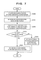
FIG. 7 is a flow chart showing the process for determining a display position in step S103 in FIG. 6;
FIG. 8 is a flow chart showing the process of a terminal management thread 2000 in FIG. 5;
FIG. 9 is a flow chart showing the process of a script management thread 3000 in FIG. 5; and
FIG. 10 is a state transition chart showing transition of the state of a gesture recognition thread 4000.
BEST MODE OF CARRYING OUT THE INVENTION
Preferred embodiments of the present invention will now be described in detail in accordance with the accompanying drawings.
FIG. 1 shows an example of the system arrangement of an image composition apparatus according to an embodiment of the present invention. FIG. 2 is a block diagram showing the system arrangement in FIG. 1. FIGS. 3A and 3B are perspective views showing an HMD (Head Mount Display) in FIGS. 1 and 2, in which FIG. 3A is a perspective view of the HMD when viewed from the front side, and FIG. 3B is a perspective view of the HMD when viewed from the rear side.
Reference numeral 100 denotes an HMD (Head Mount Display) a person wears on his or her head; 200, a three-dimensional position sensor main body; 210, a three-dimensional position sensor fixed station; 220, a hand position sensor; 300, an information processing apparatus; 400, a video camera; 500, a video deck; and 600, a terminal. These components constitute an image composition apparatus.
The HMD 100 is an eyeglass-type image display apparatus that adopts a video see-through system. This HMD 100 comprises a right-eye camera 110, left-eye camera 111, HMD built-in sensor (three-dimensional sensor mobile station) 120, right-eye LCD (Liquid crystal display) 130, and left-eye LCD 131. Note that the HMD 100 may adopt a combination of an optical see-through HMD and video camera in place of the video see-through HMD.
The right-eye camera 110 of the HMD 100 is connected to a video capture card 320 of the information processing apparatus 300, and the left-eye camera 111 is connected to a video capture card 321 of the information processing apparatus 300. The right-eye LCD 130 is connected to a video card 330 of the information processing apparatus 300, and the left-eye LCD 131 is connected to a video card 331 of the information processing apparatus 300. The LCDs 130 and 131 display a composite video of those actually captured by the left-eye camera 111 and right-eye camera 110, and, for example, script data or a video from the video camera 400 (FIG. 4).
The video to be displayed on the HMD 100 is generated by the information processing apparatus 300. The information processing apparatus 300 comprises a CPU 301, memory 302, PCI bridge 303, hard disk I/F 340, hard disk 350, and the like in addition to a serial I/O 310, the video capture cards 320, 321, and 322, and video cards 330 and 331 mentioned above.
The three-dimensional position sensor 200 comprises the three-dimensional position sensor fixed station 210 and the three-dimensional sensor mobile station 120 which is built in the HMD. The three-dimensional position sensor 200 measures the relative position between the three-dimensional position sensor fixed station 210 and three-dimensional sensor mobile station 120 by magnetism. Position information has six degrees of freedom: X, Y, Z, ROLL, PITCH, and YAW. The three-dimensional position sensor main body 200 communicates with the information processing apparatus 300 via a serial interface. The position of the three-dimensional position sensor fixed station 210 is precisely measured in advance, and the absolute position (to have the center of a studio as an origin) of the HMD can be detected by detecting the relative position of the three-dimensional sensor mobile station 120.
The three-dimensional sensor mobile station 120 is connected to the three-dimensional position sensor main body 200. The three-dimensional position sensor fixed station 210 is connected to this three-dimensional position sensor main body 200, and the hand position sensor 220 that the person who wears the HMD 100 wears on the hand is further connected. The hand position sensor 220 has the same structure as the three-dimensional sensor mobile station 120, and is also connected to the three-dimensional position sensor main body 200. In this embodiment, the hand position sensor 220 and three-dimensional position sensor 200 communicate with each other by magnetism. The three-dimensional position sensor main body 200 is further connected to the serial I/O 310 of the information processing apparatus 300. These sensors measure both the posture of a person who wears the HMD 100, and the position of the HMD 100.
This embodiment uses a magnetic position sensor which is separated into a fixed station and position sensor, but may use a position sensor using a gyro as long as it can measure the position of the HMD. The terminal 600 is used to input instructions from a staff member or to input shooting start and stop instructions.
The configuration of programs which run on the information processing apparatus 300 will be explained below. In the following description, assume that a performer wears the HMD 100 in rehearsal upon shooting a movie or television program.
FIG. 5 shows the configuration of programs which run on the information processing apparatus 300 in FIG. 2. The programs include an HMD display thread 1000, terminal management thread 2000, script management thread 3000, and gesture recognition thread 4000. Data are exchanged among the threads via an instruction buffer 2001, script buffer 3002, and display mode flag 4001.
The HMD display thread 1000 displays videos captured by the right-eye camera 110 and left-eye camera 111 on the LCDs 130 and 131. In this case, the thread 1000 superimposes an instruction from a staff member written in the instruction buffer 2001 or script data written in the script buffer 3002. Also, an image taken by the television camera 400 is also superimposed.
The process of the HMD display thread 1000 will be explained below. FIG. 6 is a flow chart showing the process of the HMD display thread 1000 in FIG. 5.
Note that the processes that pertain to the eyes of a person who wears the HMD 100 have no difference for the right and left eyes, and are basically the same. Hence, the process for the right eye will be explained below.
A video from the video camera 100 is captured by the information processing apparatus 300 via the video capture card 320 (step S100). The captured video is written on a video buffer on the memory 302 (step S101). This video buffer is a work area for storing a video during generation. By writing the captured actually taken video, an actually taken video can be used as a background image.
It is checked if an information display mode for displaying information such as a video from the video camera 400, a script, an instruction from a staff member, or the like is set. If the information display mode is set, an information display process starts (step S102).
In the information display process, the display position of information is determined to be a position where information does not disturb the performer (step S103). In this embodiment, the display position of information is set to be a position where information overlaps a table, the coordinate position of which is known, so that the information does not occlude another performer. Note that determination method of the information display position will be explained later.
After the information display position is determined, a video from the video camera 400, script data 350, and an instruction from a staff member via the terminal 600 are captured (step S104), and the captured information is written in a video buffer area corresponding to the determined display position (step S105). Since the video from the HMD 100 has already been written in the video buffer, information is superimposed on that video.
Upon completion of rendering, the contents of the video buffer are transferred to a frame buffer on the video board 330 to display (render) the contents (video) of the video buffer on the LCD 130 in the HMD 100 (step S106).
The determination method of the information display position in step S103 will be described below.
FIG. 7 is a flow chart of the process for determining the information display position in step S103 in FIG. 6.
The position of the HMD 100 is acquired from the three-dimensional sensor main body 200 (step S200). The information processing apparatus 300 generates and sets a modeling conversion matrix on the basis of the position acquired in step S200, the coordinate position of the HMD 100, and parameters such as the focal length of the camera and the like, which are measured in advance, so as to obtain an image from the viewpoint of the HMD 100 (step S201). Note that the “position and posture of the viewpoint of an observer”, which are required to estimate a real image that a person who wears the HMD 100 observes, are detected using the HMD built-in position sensor 120 in this embodiment, but the present invention is not limited to such specific method. A position sensor separate from the HMD 100 may be attached to the head of the person to detect the position and posture of the head.
The generated modeling conversion matrix converts the known coordinates of the four corners of the table into points on the screen of the LCD 130 (step S202). With this conversion, the display positions of the four corners of the table within the screen of the HMD 100 can be determined.
It is checked if all the four corners fall within the screen (step S203). If all the four corners fall within the screen (YES instep S203), the center of the four corners is set to be the information display position (step S204). In this way, information is displayed on the table. If the four corners do not fall within the screen (NO in step S203), a predetermined lower right position is set to be the central position of information display (step S205).
An example of the aforementioned image composition process will be explained below with reference to FIG. 4. FIG. 4 shows a state wherein a video 4 b taken by the video camera 400, and information from the script data 350 are superimposed on a video 4 a obtained by the video cameras 110 and 111 of the HMD 100. With the process in step S103 mentioned above, the display position of the video from the video camera 400 and information from the script data 350 are determined to be the center of the four corners of the table, and the video and the information are rendered, as indicated by a video 4 c. The videos 4 a and 4 c are composited to obtain a video 4 d, which is observed by the person who wears the HMD 100. Note that FIG. 4 typically illustrates the respective videos, and some of the video contents, composite positions, and the like are not accurate.
In this embodiment, as described previously, since the information is superimposed on the table, the coordinate position of which is known, the field of view of the performer can be prevented from being intercepted. Display of information on the table does not limit the present invention. For example, information may be superimposed on a portion of a wall, the coordinate position of which is known. Furthermore, the position of the display can be dynamically changed. For example, the position of the display may be changed from a desk to a wall.
The terminal management thread 2000 in FIG. 5 mainly processes an input from the terminal 600, and writes an instruction from a staff member to the performer via the terminal 600 in the instruction buffer 2001. At the same time, the terminal management thread 2000 informs the script management thread 3000 of staff member's operations.
The process of the terminal management thread 2000 will be described below.
FIG. 8 is a flow chart showing the process of the terminal management thread 2000 in FIG. 5.
The terminal management thread 2000 normally waits for an input from the terminal 600 (step S300). In this embodiment, a shooting start or stop command or the like is issued by inputting a character string to the terminal 600. However, the present invention is not limited to such specific instruction method to the terminal 600, and various other known user interfaces may be used.
It is checked if an input character string is a shooting start command (step S301). If the input character string is a shooting start command, a script output thread starts (step S304). If it is determined as a result of checking in step S301 that the input character string is not a shooting start command, it is checked if the input character string is a shooting stop command (step S302). If the input character string is a shooting stop command, the script output thread stops (step S305). If it is determined as a result of checking in step S302 that the input character string is not a shooting stop command, it is determined that the input character string is an instruction from a staff member to the performer, and that character string is written in the instruction buffer 2001 (step S303). After that, the flow returns to step S300.
The script management thread 3000 writes script data stored in the hard disk 350 in the script buffer 3002 at timings according to time stamps stored in the script data. The script data is stored as a sequence of sets of time stamps and character strings to be displayed at those timings.
The process of the script management thread 3000 will be described below.
FIG. 9 is a flow chart showing the process of the script management thread 3000 in FIG. 5.
As an initial setup process, an internal shooting clock 3001 is reset to zero, and a pointer of script data is returned to the head of the script (step S400).
Data (next script data to be displayed) pointed by the pointer of the script data is loaded from the hard disk 350 (step S401). The control waits until the shooting clock 3001 becomes the same as the time stamp of the script data pointed by the pointer (step S402).
The script data pointed by the pointer is written in the script buffer (step S403). The pointer of the script data is advanced (step S404), and the flow returns to step S401 to repeat the aforementioned steps.
The gesture recognition thread 4000 in FIG. 5 recognizes a gesture (hand position and posture) of the performer on the basis of the position of the hand position sensor 220 obtained via the three-dimensional position sensor main body 200. Every time a gesture is recognized, the display mode flag 4001 is turned on/off.
In this embodiment, as a gesture for turning on/off display, an action for moving the hand up and down three times for a second is selected.
FIG. 10 is a state transition chart showing transition of the state of the gesture recognition thread 4000.
The gesture recognition thread 4000 is normally in a “standby state S500”. At this time, an internal counter for counting upward and downward actions of the hand is cleared to zero. Upon detecting an upward acceleration from the hand position sensor 220, the gesture recognition thread 4000 transits to an “upward acceleration state S501”.
When the acceleration has stopped, the gesture recognition thread 4000 transits to an “upward acceleration stop state S502”. However, if an upward acceleration is detected again within 0.1 sec after transition, the gesture recognition thread 4000 returns to the “upward acceleration state S501”.
If no acceleration is detected within 0.1 sec after transition to the “upward acceleration stop state S502”, it is determined that the action detected is merely an upward movement of the hand but is not a gesture, and the gesture recognition thread 4000 transits to the “standby state S500”.
When an upward acceleration is detected in the “upward acceleration stop state S502”, the gesture recognition thread 4000 transits to the “upward acceleration state S501”.
When a downward acceleration is detected in the “upward acceleration stop state S502”, the gesture recognition thread 4000 transits to a “downward acceleration state S503”. When the acceleration has stopped, the gesture recognition thread 4000 transits to a “downward acceleration stop state S504”. When a downward acceleration is detected again within 0.1 sec after transition, the gesture recognition thread 4000 returns to the “downward acceleration state S503”.
When an upward acceleration is detected in the “downward acceleration stop state S504”, the gesture recognition thread 4000 transits to the “upward acceleration state S501”. At this time, the internal counter is incremented. This corresponds to a case wherein the hand is moved downward after upward movement.
When no acceleration is detected within 0.1 sec after transition to the “downward acceleration stop state S504”, the gesture recognition thread 4000 transits to the “standby state S500”. If counter=3, it is determined that the gesture is complete, and an event is generated to invert the value (TRUE/FALSE) of the display mode flag 4001.
The gesture recognition thread 4000 executes the process according to the aforementioned state transition chart to detect an event. In the above description, a full-superimpose display ON/OFF instruction is issued by a gesture. However, for example, display of script data, instruction data, and video camera image may be individually turned on/off, as is known to those who are skilled in the art.
As described above, according to the image composition apparatus of this embodiment, various kinds of information can be given to the performer by superimposing a desired image.
Such information can be displayed at a position (e.g., on the wall of a shooting background) where the displayed information does not disturb the field of view of the performer.
In this way, the performer can confirm lines, director's instruction, taken video, and the like without largely moving the line of sight, and the load on the performer can be reduced.
The performer can act while observing a video which is being taken by a cameraman, and which cannot so far be confirmed until after action.
Furthermore, since display of such information can be turned on/off by a performer's gesture, information can be easily displayed at a desired timing in rehearsal.
Note that the objects of the present invention are also achieved by supplying a storage medium, which records a program code of a software program that can implement the functions of the above-mentioned embodiments to the system or apparatus, and reading out and executing the program code stored in the storage medium by a computer (or a CPU or MPU) of the system or apparatus.
In this case, the program code itself read out from the storage medium implements the functions of the above-mentioned embodiments, and the storage medium which stores the program code constitutes the present invention.
As the storage medium for supplying the program code, for example, a floppy disk, hard disk, optical disk, magneto-optical disk, CD-ROM, CD-R, magnetic tape, nonvolatile memory card, ROM, and the like may be used.
The functions of the above-mentioned embodiments may be implemented not only by executing the readout program code by the computer but also by some or all of actual processing operations executed by an OS (operating system) running on the computer on the basis of an instruction of the program code.
Furthermore, the functions of the above-mentioned embodiments may be implemented by some or all of actual processing operations executed by a CPU or the like arranged in a function extension board or a function extension unit, which is inserted in or connected to the computer, after the program code read out from the storage medium is written in a memory of the extension board or unit.
As described in detail above, according to the image composition apparatus, since another image is displayed on a display unit that displays a real image, the other image can be superimposed on the real image. Hence, the user who wears display means on the head can observe the other image superimposed on the real image.
When text information is displayed as the other image, a text instruction can be given to the user who wears the display means on the head.
The other image can be an image from a viewpoint other than that of the user who wears the display means, which is taken by image taking means (television camera 400). For this reason, when this image taking means takes an image of the user who wears the display means on the head, the user can confirm his or her actions in real time.
Superimpose display of the other image in the HMD 100 is turned on/off on the basis of the hand position, hand movement, posture, and the like of the user who wears the display means. For this reason, the user can easily turn on/off superimpose display of the other image according to his or her will by changing the hand position and posture.
Since the superimpose display region of the other image is determined based on the posture of the user who wears the display means, the other image can be displayed at a position where that image does not disturb the user.
As many apparently widely different embodiments of the present invention can be made without departing from the spirit and scope thereof, it is to be understood that the invention is not limited to the specific embodiments thereof except as defined in the claims.

Claims (15)

1. An image composition system for compositing a real image corresponding to a position of a display unit with an other image, said system comprising:
the display unit, which is wearable on a head of a user, and displays a composite image;
a position sensor for detecting the position of the display unit, and position information;
a determination unit for determining a display region where the other image is to be displayed, in accordance with position information; and
a composition unit for compositing the other image on the determined display region,
wherein the other image is used to display information that helps operations of the user, and
wherein said determination unit comprises:
(a) a setting unit for setting a space region for displaying the other image in the real space; and
(b) a conversion unit for converting the space region set by said setting unit into the display region on said display unit on the basis of a position and posture of the user.
2. The system according to claim 1, wherein said display unit has an optical see through structure, and the user can observe the real space via said display unit.
3. The system according to claim 1, further comprising: a first image taking device for obtaining a video of the real space observed from a viewpoint of the user, and
wherein said composition unit displays the video obtained by said first image taking device on said display unit, and superimposes the other image on the display region determined by said determination unit.
4. The system according to claim 1, wherein the information is a video obtained by a second image taking device for taking an image from a viewpoint other than a viewpoint of the user.
5. The system according to claim 1, wherein the information is dialog information.
6. The system according to claim 1, wherein the information is an image obtained by taking an image of an action of the user.
7. An image composition system for compositing a real image corresponding to a position of a display unit with an other image, said system comprising:
the display unit, which is wearable on a head of a user, and displays a composite image;
a position sensor for detecting the position of the display unit, and outputting position information;
a determination unit for determining a display region where the other image is to be displayed, in accordance with the position information;
a composition unit for compositing the other image on the determined display region, wherein the other image is used to display information that helps operations of the user, and wherein the information is text information; and
a memory for holding a pair of the text information and time information indicating a display timing of the text information,
wherein said composition unit switches the text information to be displayed on the display region in accordance with the time information held by said memory.
8. An image composition system for compositing a real image corresponding to a position of a display unit with an other image, said system comprising:
the display unit, which is wearable on a head of a user, and displays a composite image;
a position sensor for detecting the position of the display unit, and outputting position information;
a determination unit for determining a display region where the other image is to be displayed, in accordance with the position information;
a composition unit for compositing the other image on the determined display region, wherein the other image is used to display information that helps operations of the user; and
a gesture detection unit capable of detecting a predetermined action of the user,
wherein said composition unit performs turn on/off display control of the other image in response to a predetermined action detected by said gesture detection unit.
9. The system according to claim 8, wherein said composition unit switches contents of the other image to be displayed on the display region in response to a predetermined action detected by said gesture detection unit.
10. An information processing method of displaying a composite image of a real image corresponding to a position of a display unit and an other image on the display unit, which is wearable on a head of a user, said method comprising the steps of:
detecting the position of the display unit, and outputting position information;
determining a display region where the other image is to be displayed, in accordance with the position information;
compositing the other image on the determined display region, wherein the other image is used to display information that helps operations of the user, and wherein the information is text information; and
holding in a memory a pair of the text information and time information indicating a display timing of the text information,
wherein said compositing step switches the text information to be displayed on the display region in accordance with the time information held by the memory.
11. A computer-readable medium that stores a computer-executable program for making a computer execute the information processing method according to claim 10.
12. An information processing method of displaying a composite image of a real image corresponding to a position of a display unit and an other image on the display unit, which is wearable on a head of a user, said method comprising the steps of:
detecting the position of the display unit, and position information;
determining a display region where the other image is to be displayed, in accordance with position information; and
compositing the other image on the determined display region, wherein the other image is used to display information that helps operations of the user, wherein said determining step comprises:
(a) a setting step of setting a space region for displaying the other image in a real space; and
(b) a converting step of converting the space region set by said setting step into the display region on the display unit on the basis of a position and posture of the user.
13. A computer-readable medium that stores a computer-executable program for making a computer execute the information processing method according to claim 12.
14. An information processing method of displaying a composite image of a real image corresponding to a position of a display unit and an other image on the display unit, which is wearable on a head of the user, said method comprising the steps of:
detecting the position of the display unit, and outputting position information;
determining a display region where the other image is to be displayed, in accordance with the position information;
compositing the other image on the determined display region, wherein the other image is used to display information that helps operations of the user; and
a gesture detecting step of detecting a predetermined action of the user,
wherein said compositing step performs turn on/off display control of the other image in response to a predetermined action detected by said gesture detecting step.
15. A computer-readable medium that stores a computer-executable program for making a computer execute the information processing method according to claim 14.
US10/658,335 2001-03-13 2003-09-10 Image composition apparatus and method Active 2024-04-26 US7365706B2 (en)

Applications Claiming Priority (3)

Application Number Priority Date Filing Date Title
JP2001-071121 2001-03-13
JP2001071121A JP4878083B2 (en) 2001-03-13 2001-03-13 Image composition apparatus and method, and program
PCT/JP2002/002298 WO2002073954A1 (en) 2001-03-13 2002-03-12 Image composition apparatus and method

Related Parent Applications (1)

Application Number Title Priority Date Filing Date
PCT/JP2002/002298 Continuation WO2002073954A1 (en) 2001-03-13 2002-03-12 Image composition apparatus and method

Publications (2)

Publication Number Publication Date
US20040056870A1 US20040056870A1 (en) 2004-03-25
US7365706B2 true US7365706B2 (en) 2008-04-29

Family

ID=18928890

Family Applications (1)

Application Number Title Priority Date Filing Date
US10/658,335 Active 2024-04-26 US7365706B2 (en) 2001-03-13 2003-09-10 Image composition apparatus and method

Country Status (3)

Country Link
US (1) US7365706B2 (en)
JP (1) JP4878083B2 (en)
WO (1) WO2002073954A1 (en)

Cited By (2)

* Cited by examiner, † Cited by third party
Publication number Priority date Publication date Assignee Title
US20060256036A1 (en) * 2005-05-11 2006-11-16 Yasuo Katano Image processing method and image processing apparatus
US10921595B2 (en) 2018-06-29 2021-02-16 International Business Machines Corporation Contextual adjustment to augmented reality glasses

Families Citing this family (47)

* Cited by examiner, † Cited by third party
Publication number Priority date Publication date Assignee Title
JP4878083B2 (en) 2001-03-13 2012-02-15 キヤノン株式会社 Image composition apparatus and method, and program
US8585476B2 (en) 2004-11-16 2013-11-19 Jeffrey D Mullen Location-based games and augmented reality systems
FR2889753A1 (en) * 2005-08-09 2007-02-16 Total Immersion Sa SYSTEM FOR USER TO VIEW A VIRTUAL COCKPIT IN A VIDEO ENVIRONMENT
FR2889754A1 (en) * 2005-08-09 2007-02-16 Total Immersion Sa SYSTEM FOR USER TO VISUALIZE A REAL COCKPIT IN A VIDEO ENVIRONMENT, IN PARTICULAR A MOTOR DRIVING ENVIRONMENT
US7697827B2 (en) 2005-10-17 2010-04-13 Konicek Jeffrey C User-friendlier interfaces for a camera
JP4652947B2 (en) * 2005-10-21 2011-03-16 キヤノン株式会社 Image display program, image display apparatus, and image display method
US7732694B2 (en) * 2006-02-03 2010-06-08 Outland Research, Llc Portable music player with synchronized transmissive visual overlays
JP4481280B2 (en) * 2006-08-30 2010-06-16 富士フイルム株式会社 Image processing apparatus and image processing method
JP2008096868A (en) 2006-10-16 2008-04-24 Sony Corp Imaging display device, and imaging display method
JP4689639B2 (en) * 2007-04-25 2011-05-25 キヤノン株式会社 Image processing system
JP5161544B2 (en) * 2007-11-16 2013-03-13 キヤノン株式会社 Image display system
JP2010033367A (en) * 2008-07-29 2010-02-12 Canon Inc Information processor and information processing method
US8957835B2 (en) 2008-09-30 2015-02-17 Apple Inc. Head-mounted display apparatus for retaining a portable electronic device with display
US9091851B2 (en) 2010-02-28 2015-07-28 Microsoft Technology Licensing, Llc Light control in head mounted displays
US9285589B2 (en) 2010-02-28 2016-03-15 Microsoft Technology Licensing, Llc AR glasses with event and sensor triggered control of AR eyepiece applications
US9366862B2 (en) 2010-02-28 2016-06-14 Microsoft Technology Licensing, Llc System and method for delivering content to a group of see-through near eye display eyepieces
US8477425B2 (en) 2010-02-28 2013-07-02 Osterhout Group, Inc. See-through near-eye display glasses including a partially reflective, partially transmitting optical element
US8472120B2 (en) 2010-02-28 2013-06-25 Osterhout Group, Inc. See-through near-eye display glasses with a small scale image source
US9097890B2 (en) 2010-02-28 2015-08-04 Microsoft Technology Licensing, Llc Grating in a light transmissive illumination system for see-through near-eye display glasses
US9229227B2 (en) 2010-02-28 2016-01-05 Microsoft Technology Licensing, Llc See-through near-eye display glasses with a light transmissive wedge shaped illumination system
US8482859B2 (en) 2010-02-28 2013-07-09 Osterhout Group, Inc. See-through near-eye display glasses wherein image light is transmitted to and reflected from an optically flat film
US9129295B2 (en) 2010-02-28 2015-09-08 Microsoft Technology Licensing, Llc See-through near-eye display glasses with a fast response photochromic film system for quick transition from dark to clear
US20120249797A1 (en) 2010-02-28 2012-10-04 Osterhout Group, Inc. Head-worn adaptive display
US8467133B2 (en) 2010-02-28 2013-06-18 Osterhout Group, Inc. See-through display with an optical assembly including a wedge-shaped illumination system
US9128281B2 (en) 2010-09-14 2015-09-08 Microsoft Technology Licensing, Llc Eyepiece with uniformly illuminated reflective display
US9182596B2 (en) 2010-02-28 2015-11-10 Microsoft Technology Licensing, Llc See-through near-eye display glasses with the optical assembly including absorptive polarizers or anti-reflective coatings to reduce stray light
US9134534B2 (en) 2010-02-28 2015-09-15 Microsoft Technology Licensing, Llc See-through near-eye display glasses including a modular image source
US8488246B2 (en) 2010-02-28 2013-07-16 Osterhout Group, Inc. See-through near-eye display glasses including a curved polarizing film in the image source, a partially reflective, partially transmitting optical element and an optically flat film
US9341843B2 (en) 2010-02-28 2016-05-17 Microsoft Technology Licensing, Llc See-through near-eye display glasses with a small scale image source
US10180572B2 (en) 2010-02-28 2019-01-15 Microsoft Technology Licensing, Llc AR glasses with event and user action control of external applications
EP2539759A1 (en) 2010-02-28 2013-01-02 Osterhout Group, Inc. Local advertising content on an interactive head-mounted eyepiece
US9097891B2 (en) 2010-02-28 2015-08-04 Microsoft Technology Licensing, Llc See-through near-eye display glasses including an auto-brightness control for the display brightness based on the brightness in the environment
US9223134B2 (en) 2010-02-28 2015-12-29 Microsoft Technology Licensing, Llc Optical imperfections in a light transmissive illumination system for see-through near-eye display glasses
US20150309316A1 (en) 2011-04-06 2015-10-29 Microsoft Technology Licensing, Llc Ar glasses with predictive control of external device based on event input
US9759917B2 (en) 2010-02-28 2017-09-12 Microsoft Technology Licensing, Llc AR glasses with event and sensor triggered AR eyepiece interface to external devices
US20120038668A1 (en) * 2010-08-16 2012-02-16 Lg Electronics Inc. Method for display information and mobile terminal using the same
KR101932688B1 (en) 2010-11-29 2018-12-28 삼성전자주식회사 Portable Device and Method for Providing User Interface Mode thereof
FR2984057B1 (en) 2011-12-13 2014-01-03 Solidanim VIDEO FILM TURNING SYSTEM
GB201208088D0 (en) * 2012-05-09 2012-06-20 Ncam Sollutions Ltd Ncam
KR20130139622A (en) * 2012-06-13 2013-12-23 한국전자통신연구원 Convergence security control system and method thereof
JP5664677B2 (en) * 2013-02-19 2015-02-04 ソニー株式会社 Imaging display device and imaging display method
KR20150008733A (en) 2013-07-15 2015-01-23 엘지전자 주식회사 Glass type portable device and information projecting side searching method thereof
JP2015152940A (en) * 2014-02-10 2015-08-24 ソニー株式会社 Presentation control device, method of controlling presentation, and program
CN105120135B (en) * 2015-08-25 2019-05-24 努比亚技术有限公司 A kind of binocular camera
US11037532B2 (en) 2016-02-08 2021-06-15 Sony Corporation Information processing apparatus and information processing method
JP6734532B2 (en) * 2016-04-22 2020-08-05 ミツミ電機株式会社 Display device
WO2023244829A1 (en) * 2022-06-16 2023-12-21 Axon Enterprise, Inc. Generating video data for simulating human perception

Citations (11)

* Cited by examiner, † Cited by third party
Publication number Priority date Publication date Assignee Title
US4758892A (en) 1984-04-27 1988-07-19 Ampex Corporation System for producing a video combine from multiple video images
US4797942A (en) 1987-03-02 1989-01-10 General Electric Pyramid processor for building large-area, high-resolution image by parts
WO1997003416A1 (en) 1995-07-10 1997-01-30 Sarnoff Corporation Method and system for rendering and combining images
US5815411A (en) 1993-09-10 1998-09-29 Criticom Corporation Electro-optic vision system which exploits position and attitude
EP1117074A2 (en) 2000-01-13 2001-07-18 Mixed Reality Systems Laboratory Inc. Augmented reality presentation apparatus and method, and storage medium
US6297856B1 (en) 1994-11-30 2001-10-02 Canon Kabushiki Kaisha Apparatus and system for reading data from a dynamic image data file
WO2002073954A1 (en) 2001-03-13 2002-09-19 Canon Kabushiki Kaisha Image composition apparatus and method
US20020154070A1 (en) 2001-03-13 2002-10-24 Canon Kabushiki Kaisha Image processing apparatus, image processing method, and control program
US6597389B2 (en) 1996-01-30 2003-07-22 Canon Kabushiki Kaisha Camera control system and camera control apparatus
US6611285B1 (en) 1996-07-22 2003-08-26 Canon Kabushiki Kaisha Method, apparatus, and system for controlling a camera, and a storage medium storing a program used with the method, apparatus and/or system
US6847336B1 (en) * 1996-10-02 2005-01-25 Jerome H. Lemelson Selectively controllable heads-up display system

Family Cites Families (9)

* Cited by examiner, † Cited by third party
Publication number Priority date Publication date Assignee Title
US6278461B1 (en) * 1993-09-10 2001-08-21 Geovector Corporation Augmented reality vision systems which derive image information from other vision systems
JPH10240491A (en) * 1997-02-26 1998-09-11 Olympus Optical Co Ltd Information processor
FR2775814B1 (en) * 1998-03-06 2001-01-19 Rasterland Sa SYSTEM FOR VIEWING REALISTIC VIRTUAL THREE-DIMENSIONAL IMAGES IN REAL TIME
US6215471B1 (en) * 1998-04-28 2001-04-10 Deluca Michael Joseph Vision pointer method and apparatus
JP2000235163A (en) * 1999-02-12 2000-08-29 Canon Inc Head-mounted type display device and warning display method thereof
JP2001034615A (en) * 1999-07-16 2001-02-09 Nippon Telegr & Teleph Corp <Ntt> Work support system and work support method
JP3406965B2 (en) * 2000-11-24 2003-05-19 キヤノン株式会社 Mixed reality presentation device and control method thereof
US7095388B2 (en) * 2001-04-02 2006-08-22 3-Dac Golf Corporation Method and system for developing consistency of motion
US6637883B1 (en) * 2003-01-23 2003-10-28 Vishwas V. Tengshe Gaze tracking system and method

Patent Citations (11)

* Cited by examiner, † Cited by third party
Publication number Priority date Publication date Assignee Title
US4758892A (en) 1984-04-27 1988-07-19 Ampex Corporation System for producing a video combine from multiple video images
US4797942A (en) 1987-03-02 1989-01-10 General Electric Pyramid processor for building large-area, high-resolution image by parts
US5815411A (en) 1993-09-10 1998-09-29 Criticom Corporation Electro-optic vision system which exploits position and attitude
US6297856B1 (en) 1994-11-30 2001-10-02 Canon Kabushiki Kaisha Apparatus and system for reading data from a dynamic image data file
WO1997003416A1 (en) 1995-07-10 1997-01-30 Sarnoff Corporation Method and system for rendering and combining images
US6597389B2 (en) 1996-01-30 2003-07-22 Canon Kabushiki Kaisha Camera control system and camera control apparatus
US6611285B1 (en) 1996-07-22 2003-08-26 Canon Kabushiki Kaisha Method, apparatus, and system for controlling a camera, and a storage medium storing a program used with the method, apparatus and/or system
US6847336B1 (en) * 1996-10-02 2005-01-25 Jerome H. Lemelson Selectively controllable heads-up display system
EP1117074A2 (en) 2000-01-13 2001-07-18 Mixed Reality Systems Laboratory Inc. Augmented reality presentation apparatus and method, and storage medium
WO2002073954A1 (en) 2001-03-13 2002-09-19 Canon Kabushiki Kaisha Image composition apparatus and method
US20020154070A1 (en) 2001-03-13 2002-10-24 Canon Kabushiki Kaisha Image processing apparatus, image processing method, and control program

Non-Patent Citations (3)

* Cited by examiner, † Cited by third party
Title
Fukumoto, "Finger Pointing"; Pointing Interface by image processing, Compt. & Graphics, vol. 18, No. 5, pp. 633-642 (1994).
Notice of Transmittal of International Preliminary Examination Report (PCT/JP 02/02298) dated May 26, 2003.
Notice of Transmittal of International Search Report (PCT/JP 02/02298) dated Aug. 6, 2002.

Cited By (3)

* Cited by examiner, † Cited by third party
Publication number Priority date Publication date Assignee Title
US20060256036A1 (en) * 2005-05-11 2006-11-16 Yasuo Katano Image processing method and image processing apparatus
US7834909B2 (en) * 2005-05-11 2010-11-16 Canon Kabushiki Kaisha Image processing method and image processing apparatus
US10921595B2 (en) 2018-06-29 2021-02-16 International Business Machines Corporation Contextual adjustment to augmented reality glasses

Also Published As

Publication number Publication date
JP4878083B2 (en) 2012-02-15
US20040056870A1 (en) 2004-03-25
WO2002073954A1 (en) 2002-09-19
JP2002268621A (en) 2002-09-20

Similar Documents

Publication Publication Date Title
US7365706B2 (en) Image composition apparatus and method
KR102517876B1 (en) Technique for recording augmented reality data
US7952594B2 (en) Information processing method, information processing apparatus, and image sensing apparatus
JP4227561B2 (en) Image processing method and image processing apparatus
JP4533087B2 (en) Image processing method and image processing apparatus
US8866811B2 (en) Image processing apparatus and image processing method
CN106716303B (en) Stablize the movement of interaction ray
JP5295714B2 (en) Display device, image processing method, and computer program
US8098263B2 (en) Image processing method and image processing apparatus
US8633871B2 (en) Image processing apparatus and image processing method
CN106066701B (en) A kind of AR and VR data processing equipment and method
US20050024388A1 (en) Image displaying method and apparatus
US20020060648A1 (en) Image-display control apparatus
CN108508603A (en) Head-mount type display unit and its control method and recording medium
JP6554948B2 (en) Display device, display device control method, and program
CN109844600A (en) Information processing equipment, information processing method and program
JP2005339266A (en) Information processing method, information processor and imaging device
US6892162B2 (en) Position-direction measuring apparatus and information processing method
JP3848092B2 (en) Image processing apparatus and method, and program
JP4217661B2 (en) Image processing method and image processing apparatus
JP2005339267A (en) Information processing method, information processor and imaging device
US20220197370A1 (en) Head mounted information processing apparatus and head mounted display system
WO2023275920A1 (en) Trigger signal generation device and mobile terminal

Legal Events

Date Code Title Description
AS Assignment

Owner name: CANON KABUSHIKI KAISHA, JAPAN

Free format text: ASSIGNMENT OF ASSIGNORS INTEREST;ASSIGNORS:SHIMOYAMA, TOMOHIKO;MORITA, KENJI;YONEZAWA, HIROKI;REEL/FRAME:014480/0017

Effective date: 20030822

STCF Information on status: patent grant

Free format text: PATENTED CASE

CC Certificate of correction
FPAY Fee payment

Year of fee payment: 4

FPAY Fee payment

Year of fee payment: 8

MAFP Maintenance fee payment

Free format text: PAYMENT OF MAINTENANCE FEE, 12TH YEAR, LARGE ENTITY (ORIGINAL EVENT CODE: M1553); ENTITY STATUS OF PATENT OWNER: LARGE ENTITY

Year of fee payment: 12