US7349469B1 - DC offset correction for constant modulus equalization - Google Patents
DC offset correction for constant modulus equalization Download PDFInfo
- Publication number
- US7349469B1 US7349469B1 US10/213,854 US21385402A US7349469B1 US 7349469 B1 US7349469 B1 US 7349469B1 US 21385402 A US21385402 A US 21385402A US 7349469 B1 US7349469 B1 US 7349469B1
- Authority
- US
- United States
- Prior art keywords
- offset
- circumflex over
- estimate
- recited
- received signal
- Prior art date
- Legal status (The legal status is an assumption and is not a legal conclusion. Google has not performed a legal analysis and makes no representation as to the accuracy of the status listed.)
- Expired - Fee Related, expires
Links
Images


Classifications
-
- H—ELECTRICITY
- H04—ELECTRIC COMMUNICATION TECHNIQUE
- H04L—TRANSMISSION OF DIGITAL INFORMATION, e.g. TELEGRAPHIC COMMUNICATION
- H04L25/00—Baseband systems
- H04L25/02—Details ; arrangements for supplying electrical power along data transmission lines
- H04L25/03—Shaping networks in transmitter or receiver, e.g. adaptive shaping networks
- H04L25/03006—Arrangements for removing intersymbol interference
- H04L25/03012—Arrangements for removing intersymbol interference operating in the time domain
- H04L25/03019—Arrangements for removing intersymbol interference operating in the time domain adaptive, i.e. capable of adjustment during data reception
- H04L25/03057—Arrangements for removing intersymbol interference operating in the time domain adaptive, i.e. capable of adjustment during data reception with a recursive structure
- H04L25/03063—Arrangements for removing intersymbol interference operating in the time domain adaptive, i.e. capable of adjustment during data reception with a recursive structure using fractionally spaced delay lines or combinations of fractionally and integrally spaced taps
-
- H—ELECTRICITY
- H04—ELECTRIC COMMUNICATION TECHNIQUE
- H04L—TRANSMISSION OF DIGITAL INFORMATION, e.g. TELEGRAPHIC COMMUNICATION
- H04L25/00—Baseband systems
- H04L25/02—Details ; arrangements for supplying electrical power along data transmission lines
- H04L25/06—Dc level restoring means; Bias distortion correction ; Decision circuits providing symbol by symbol detection
- H04L25/061—Dc level restoring means; Bias distortion correction ; Decision circuits providing symbol by symbol detection providing hard decisions only; arrangements for tracking or suppressing unwanted low frequency components, e.g. removal of dc offset
-
- H—ELECTRICITY
- H04—ELECTRIC COMMUNICATION TECHNIQUE
- H04L—TRANSMISSION OF DIGITAL INFORMATION, e.g. TELEGRAPHIC COMMUNICATION
- H04L25/00—Baseband systems
- H04L25/02—Details ; arrangements for supplying electrical power along data transmission lines
- H04L25/03—Shaping networks in transmitter or receiver, e.g. adaptive shaping networks
- H04L25/03006—Arrangements for removing intersymbol interference
- H04L2025/0335—Arrangements for removing intersymbol interference characterised by the type of transmission
- H04L2025/03375—Passband transmission
- H04L2025/03382—Single of vestigal sideband
Definitions
- the present invention relates to an equalizer in a receiver of a digital communications system, and more particularly, to blind equalization of modulated data with a DC offset.
- a source In many digital communications systems, a source generates digital information for transmission to multiple destination receivers.
- a transmitter processes the digital information into an encoded (e.g., error-correction encoded) and/or packetized stream of data.
- the stream of data is then divided into discrete blocks. Each of the blocks is mapped onto a corresponding one of a sequence of code or symbol values (“symbols”) chosen from a pre-defined alphabet, and generated with a period T s , sometimes referred to as the “baud” period.
- symbols may be modulated by an analog, e.g., radio frequency (RF), carrier, in amplitude, phase, and/or frequency prior to physical transmission through the communication medium.
- RF radio frequency
- mapping many methods of mapping exist and are well known in the art, and these pre-defined alphabets are generated based on certain criteria. For example, data may be mapped into symbols of a complex data stream as pairs of in-phase (I) and quadrature phase (Q) component values that are subsequently modulated with an RF carrier.
- I in-phase
- Q quadrature phase
- modulation techniques such as pulse amplitude modulation (PAM), quadrature amplitude modulation (QAM), phase-shift keyed (PSK) modulation, or vestigial sideband (VSB) modulation are known in the art of communications to modulate the carrier.
- PAM pulse amplitude modulation
- QAM quadrature amplitude modulation
- PSK phase-shift keyed
- VSB vestigial sideband modulation
- modulation formats such as PAM, QAM, and complex VSB are common formats used for transmission of digital television signals in accordance with, for example, the ATSC standard for digital television, “ATSC Digital Television Standard,” September 1995.
- a quadrature oscillator may be employed with a complex RF upconverter to form a modulator.
- the I-component modulates the cosine component generated by the oscillator and the Q-component modulates the sine component of the oscillator.
- VSB modulation is a form of single-sideband modulation in which the redundant sideband of a real-valued signal is removed in full by filtering, except for a small vestige of the sideband.
- a complex signal is formed with the Q-component being the Hilbert transform of the I-component (however, the Q-component thus contains no additional user information).
- a transmitter may also insert a pilot and/or other reference into the modulated carrier signal prior to transmission to aid the receiver in carrier synchronization and recovery.
- a pilot and/or other reference For example, 10 Megabaud terrestrial broadcast of Digital Television (DTV) signals in the United States employs single-carrier, single sideband modulation (known as 8-VSB for 8-level Vestigial Sideband Modulation).
- 8-VSB single sideband modulation
- a narrowband pilot tone is inserted into the lower band edge of the 8- or 16-VSB data spectrum, containing about 7.5 percent of the power of the data spectrum, to aid in carrier synchronization.
- the reference signal is applied as a 1.25 DC offset to the VSB constellation.
- the DC offset applied is 1.25.
- Other references added may include training sequences to aid in equalization by the receiver.
- the modulated carrier signal transmitted through the medium comprises a series of analog pulses, each analog pulse being amplitude and/or phase modulated by a corresponding symbol in the sequence.
- the pulse shape used typically extends many symbol periods in time. This introduces the possibility of adjacent pulses corrupting each other, a phenomenon known as inter-symbol interference (ISI).
- ISI inter-symbol interference
- Most propagation mediums introduce signal distortion, and factors that cause distortion include added noise (static), signal strength variations (fading), phase shift variations, and multiple path delays.
- front-end circuitry of the receiver and transmitter also introduce distortion and noise to the signal.
- the presence of distortion, noise, fading and multipath introduced by the overall communication channel (transmitter, receiver and propagation medium) can cause digital systems to degrade or fail completely when the bit error rate exceeds some threshold and overcomes the error tolerance of the system.
- a receiver performs several functions to demodulate and decode a received signal.
- Receiver functions include, for example, tuning and RF demodulation of the received signal to an intermediate frequency (IF) signal, synchronization with the RF carrier, equalization, symbol detection, and decoding.
- IF intermediate frequency
- a complex demodulator translates the received signal from RF to intermediate frequency (IF), and performs complex demodulation of the received signal at IF to near passband employing the locally generated reference for the carrier signal.
- the receiver includes synchronization of the locally generated reference to the carrier of the received signal. As mentioned previously, synchronization may employ a pilot embedded in the received signal to align the locally generated reference with the carrier phase of the received signal.
- the demodulated signal is then sampled based on an estimate of the symbol period. Timing recovery estimates the symbol period, and this estimate may be fed back to the complex demodulator and sampler to adjust the sampling rate (e.g., via a sampling phase error).
- Equalization of the received samples suppresses the effects of ISI, caused by phenomena such as i) residual timing error, ii) pulse shape/multipath distortion from the propagation channel, and/or iii) approximation of the ideal transmit and receive filters for ease of implementation.
- Carrier recovery generates estimates for the difference in frequency and phase (collectively referred to as angle ⁇ ) of the carrier used to modulate the symbols and the locally generated reference used for demodulation.
- a slicer examines each sample to generate either a soft or hard decision for the symbol that corresponds to the sample(s) under study.
- a slicer is a decision device that, responsive to the signal at its input, generates the projection of the nearest symbol value to the input signal from the grid of constellation points. The output of the slicer thus corresponds to one of the allowed, discrete levels.
- a decoder reconstructs the transmitted data from the symbol sequence.
- Equalization may be accomplished using a filter that has the inverse channel function of the communication channel.
- An estimate of the transmission characteristics of the communication channel (transfer function or impulse response) is either known or measured, and the equalization filter parameters may be set indirectly based on the estimate.
- the received signal is then passed through the equalizer, which compensates for the non-ideal communication channel by introducing “distortions” into the received signal which tend to cancel the distortions introduced by the communication channel.
- each receiver is in a unique location with respect to the transmitter. Accordingly, the characteristics of the communication channel are not known in advance, and may even change over time.
- the equalizer may typically be an adaptive equalizer having variable filter parameters, or filter tap coefficients (“taps”), that are calculated by the receiver.
- taps filter tap coefficients
- the parameters of the equalizer filter(s) are set using a predetermined reference signal transmitted with the data, sometimes referred to as a training sequence.
- a receiver typically employs blind equalization.
- blind equalization the equalizer's filter parameters are derived from the received signal itself, rather than by using a training sequence.
- a signal when a signal includes a pilot, or DC offset component, included during modulation for synchronization, the pilot signal component degrades equalization performance of a receiver. Such performance may be significantly degraded when the receiver performs blind equalization.
- Prior art systems typically notch out the DC component in the frequency domain (i.e., notch filtering), or subtract the DC component from the signal (constellation) in the time domain. In the frequency domain, notch filtering generally introduces distortion and notch noise since the notch filter is not as narrow as the DC component that is filtered out. In the time domain, subtracting the DC component from the signal requires an estimate of the level of DC component at the receiver. The DC component is difficult to estimate since the magnitude of the DC component varies due to channel effects (e.g., noise, dispersion, and gain/attenuation) that vary with time.
- channel effects e.g., noise, dispersion, and gain/attenuation
- the combined equalizer-channel response approximates a pure delay and is the inverse of the channel response.
- the contribution of f* with the impulse response of the channel and receiver is the approximate inverse equalizer solution.
- the l-th component of the vector s (n) is denoted a l (n)+p, where p represents a DC offset component that is included in the signal inserted at the transmitter.
- the DC offset component seen at the receiver may or may not be equivalent to the DC offset p introduced at the transmitter because of channel effects.
- Additive perturbations on the channel are included in the noise vector w (n) of dimension N.
- the noise contribution may be filtered by the receiver filter f of same dimension.
- the equalizer through the vector h , processes the source sequence.
- the CM criterion penalizes the deviation of the dispersion of the magnitude squared of the received signal from a pre-calculated constant referred to as the “dispersion constant” or the “Godard radius.”
- FIGS. 1A and 1B illustrate that the CM criterion is based on deviation from a “radius” about the origin of, for example, a source constellation.
- FIG. 1A shows a radius 101 of an 8-PSK (phase-shift keyed) constellation plotted for real (e.g., Re or I) and imaginary (e.g., Im or Q) components.
- real e.g., Re or I
- imaginary e.g., Im or Q
- each point (symbol) lies on the circle 104 defined by this radius 101 (termed a constant modulus system), and the CM criterion penalizes distance of a received sample (e.g., sample 102 ) from this circle 104 . Even though the constellation may rotate, the constellation remains on the circle, and so applying a CM criterion to this constellation does not penalize spatial rotation of the constellation due to residual carrier offset.
- FIG. 1B shows a 16-QAM (quadrature amplitude modulation) constellation plotted for real and imaginary components. In FIG. 1B , groups of points (symbols) lie on corresponding concentric circles 111 , 112 , and 113 .
- the CM criterion defines a radius 114 of circle 115 , which is not necessarily a radius of one of the concentric circles 111 , 112 and 113 (termed non-constant modulus), as a “common” radial distance from the origin for the points of the constellation. As with the constellation of FIG. 1A , the CM criterion penalizes distance of a received sample (e.g., sample 103 ) from this circle 115 .
- J CM E[ (
- E[•] denotes the expected value
- ⁇ is the dispersion constant (also known as the Godard radius)
- y n (f) is the discrete value that represents the sampled signal (see, e.g., equation (1)
- f represents the linear filter (e.g., equalizer taps) introduced to suppress the ISI.
- the dispersion constant ⁇ is a quantity that can be determined from the type of modulation employed (e.g., QAM, BPSK, etc.).
- the dispersion constant ⁇ may be derived by calculation, by experiment, or by a combination of both for a particular implementation.
- the subscript “n” in the notation, such as y n indicates that the values are discrete time.
- notation of variables such as “y(n)” and “y n ” as used herein are equivalent.
- the dispersion coefficient ⁇ may be defined given as in equation (3):
- Equation (2) may be jointly optimized. Joint optimization allows for optimization of two or more variables of interest together. For example, the discrete value y n ( ⁇ ,0) may be dependent upon timing ⁇ and phase ⁇ . Substitution of y n ( ⁇ , ⁇ ) in equation (2) then yields a CM cost function that may be optimized, such as by deriving the gradient, with respect to timing ⁇ and frequency ⁇ .
- the CM criterion may be modified by taking the real part of y n (f) in equation (3).
- the modified CM criterion is referred to as the single-axis (SA) CM criterion, and is given in equation (4).
- J SA-CM E[ ( Re ( y n ( f )) 2 ⁇ ) 2 ] (4) where Re ⁇ • ⁇ denotes the real-part extraction.
- the SA-CM criterion may be defined for VSB signals, such as described in a paper by Shah et al, “Global convergence of a single-axis constant modulus algorithm,” Proceedings of the Statistical Signal and Array Processing Workshop, Pocono Manor, Pa., August 2000, which is incorporated herein by reference.
- SA-CM for VSB signals and blind cost error terms generated from the stochastic gradient of SA-CM criterion are also described in U.S. Pat. No. 6,418,164, entitled “A REDUCED COMPLEXITY BLIND EQUALIZER FOR MULTI-MODE SIGNALING,” issued on Jul. 9, 2002, which is incorporated herein by reference.
- the gradient of the cost function may be derived.
- the stochastic gradient is an approximation of the true gradient that is calculated by taking the derivative of the cost function without taking the expected value.
- the stochastic gradient of the CM criterion is known as the CM algorithm (CMA) and is derived by taking the derivative of equation (2) with respect to the variable of interest (for the gradient of the single-axis CM, the derivative is taken of equation (2) with respect to the (equalizer tap) function f).
- CM cost criterion admits local spurious minima in terms of the equalizer function applied to the received signal.
- the present invention relates to generating an estimated correction for DC offset during equalization applied to a received signal.
- the estimated correction is then incorporated into the cost function, such as the constant modulus (CM) cost criterion, that may be employed to adaptively set equalizer parameters, such as tap coefficients.
- the estimate is generated by jointly minimizing a Constant Modulus (CM) cost function over a channel function related to the equalizer parameters and an estimate of DC offset in the received signal.
- CM Constant Modulus
- a level offset in a received signal is estimated by (a) generating an estimate of the offset from one or more current samples of the received signal based on a joint minimization of a cost criterion with respect to a channel response and the offset; and (b) adjusting the estimate of the offset based on one or more subsequent samples of the received signal in accordance with the joint minimization.
- FIG. 1A illustrates a constant modulus criterion based on determining a radius about the origin of an 8-PSK source constellation
- FIG 1 B illustrates a constant modulus criterion based on determining a radius about the origin of a 16-QAM source constellation
- FIG. 2 shows a receiver coupled to propagation medium and including an equalizer operating in accordance with exemplary embodiments of the present invention
- FIG. 3 shows the contour of the CM criterion with a first DC offset
- FIG. 4 shows the contour of the CM criterion with a second DC offset
- FIG. 5 is a flow chart illustrating the method of DC offset correction in accordance with an exemplary embodiment of the present invention.
- FIG. 6 shows a block diagram of a pilot removal generator and a tap update generator implementing a method of DC offset correction such as shown in FIG. 5 ;
- the present invention relates to generating an estimated correction for DC offset during equalization applied to a received signal.
- the estimated DC offset is incorporated into the cost function, such as the constant modulus (CM) cost criterion that is employed to adaptively set equalizer parameters, such as tap coefficients, approximating the inverse of the channel response through which the received signal passes.
- the estimated DC offset is generated by jointly minimizing a Constant Modulus (CM) cost function over the equalizer function and estimated DC offset.
- CM Constant Modulus
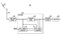
- FIG. 2 shows receiver 200 coupled to propagation medium 201 by sensor 202 .
- Receiver 200 includes equalizer 204 operating in accordance with an exemplary embodiment of the present invention. Through sensor 202 , receiver 200 detects and receives signals passing through medium 201 . Receiver 200 receives signals that are generated and passed to medium 201 by a transmitter, such as a broadcast station (not shown), that encodes and modulates an information source s(n) (such as video, audio and/or other data). The encoded signal s(n) is modulated onto the phase and/or amplitude of a suitable carrier frequency for transmission through medium 201 .
- a transmitter such as a broadcast station (not shown)
- the encoded signal s(n) is modulated onto the phase and/or amplitude of a suitable carrier frequency for transmission through medium 201 .
- Receiver 200 may be employed in a digital communication system broadcasting digital television signals in accordance with, for example, the ATSC standard for digital television, “ATSC Digital Television Standard,” September 1995. Consequently, the preferred embodiments of the present invention operate on received signals having complex VSB modulation format.
- VSB is the modulation format adopted for terrestrial broadcast of digital television signals in the United States by the ATSC standard.
- the present invention is not so limited and may be employed with other modulation formats, such as pulse amplitude modulation (PAM) and quadrature amplitude modulation (QAM) commonly employed in digital television broadcast standards.
- PAM pulse amplitude modulation
- QAM quadrature amplitude modulation
- Receiver 200 includes front-end circuitry 203 that performs several functions.
- Front-end circuitry 203 includes complex demodulation of the received signal from RF to intermediate frequency (IF), and complex demodulation of the received signal at IF to near passband employing a locally generated reference for the carrier signal.
- the demodulated signal is sampled based on an estimate of the symbol period, and timing recovery estimates the symbol timing period.
- the sampling rate may be adjusted via feedback (e.g., via a sampling phase error). Timing recovery may then track variations in the detected period and phase of the symbol period.
- Equalizer 204 provides equalization of the received signal to compensate for inter-symbol interference (ISI), a distortion, and similar channel effects (here, the term channel may also include effects of front-end circuitry 203 ). Equalization may be accomplished with forward and feedback filters (not shown in FIG. 2 ) realizing an infinite impulse response (IIR) equalizer, or an IIR in a decision feedback equalizer (DFE). Equalizer 204 includes equalizer filter 208 that applies an equalization filter function to the received signal input to equalizer 204 , and equalizer filter 208 may be defined by a set of filter tap values. Equalizer 204 further comprises a pilot removal generator 210 and tap update generator 212 .
- ISI inter-symbol interference
- DFE decision feedback equalizer
- Carrier recovery may be employed to estimate carrier phase error for rotation/de-rotation of equalized samples, and may be implemented within equalizer 204 .
- Decision device 205 e.g., a slicer
- Decoder 206 decodes the symbols from decision device 205 , and may include forward error correction (FEC) decoding.
- FEC forward error correction
- Equalizer filter 208 of equalizer 204 may be implemented as a multi-tap filter where the tap coefficients are adaptively set by tap update generator 212 .
- Such adaptive equalization employs a cost function, which for the preferred embodiments is the constant modulus (CM) cost criterion, and may be the CM cost function defined for single axis functions (SA-CM cost function). More specifically the actual or estimated error is derived from the minimization of the cost function with respect to the variable(s) of interest, which may be a joint optimization including the variable estimated DC offset. In practice, the optimization yields an error term between actual and desired value of the variable of interest. To generate the estimate of the error for a given sample or observation, a recursive update algorithm may be employed. Correction for DC offset in accordance with exemplary embodiments of the present invention accounts for the DC offset within the error terms generated for the cost function.
- Equation (1) The data model as described in equation (1) may be employed for use with equalizer 204 .
- the vector s n contains a group of symbols representing the signal of interest coming from a single source or multiple sources
- the vector w n represents added white noise
- the vector h denotes the combined finite impulse response of the channel-receiver system
- the vector f denotes the finite impulse response of the linear filter applied to the added white noise.
- the subscript “n” in the notation, such as y n indicates that the values are discrete time.
- notation of variables such as “y(n)” and “y n ” as used herein are equivalent.
- the noise vector w n of dimension N may be Gaussian, temporally and spatially white with zero-mean and variance E ⁇ w 2 ⁇ .
- the noise contribution is filtered by the linear receiver function f of same dimension.
- Vectors h and s n are defined having a length M, M an integer greater than zero.
- CM-derived adaptive equalizer for, for example, equalizer 204 is now described.
- a new CM cost function is defined in which an estimate of the DC offset is subtracted from the received channel output y n (f).
- the parameter ⁇ circumflex over (p) ⁇ represents a value (estimate) introduced in the receiver (e.g., equalizer 204 ) to compensate for the DC component p that is inserted in the transmitter.
- CM-based equalization determines the joint minima of the new CM cost function (e.g., either equation (2) or (4) accounting for estimate ⁇ circumflex over (p) ⁇ ).
- the joint minima of a CM cost function may be defined as the minima of the function J SA-CM (dc) in equation (5) with respect to the filter vector f and estimate ⁇ circumflex over (p) ⁇ .
- the dispersion constant of the CM criterion is denoted by ⁇ .
- the local minima of parameter ⁇ circumflex over (p) ⁇ of the function J SA-CM (dc) are denoted ⁇ circumflex over (p) ⁇ * .
- M ⁇ 1 ⁇ are global minima of the function J SA-CM (dc) ( h , ⁇ circumflex over (p) ⁇ ) (note that h and f are related through h being the combination of filter response f with the channel response). Polarity of the global minima is determined from the corresponding sign of the DC offset that is embedded by the transmitter.
- the global minima of the CM criterion change when the DC offset is known by the receiver (if the DC offset p introduced at the source is removed at the output of the CM receiver).
- FIGS. 3 and 4 further illustrate the effects of correction for signal bias arising from DC offset.
- FIGS. 3 and 4 show contour lines for the cost surface of the criterion of equation (4) for h defined with a two-tap, global impulse response and BPSK signaling (a t ⁇ 1) for symbols s n .
- the DC offset estimate at the receiver is selected as substantially equivalent to the DC offset inserted at the transmitter, and, in both cases, the CM criterion admits the pair of desirable global minima (0, 1) and (1,0).
- the minima at negative polarities i.e., those closest to (0, ⁇ 1) and ( ⁇ 1, 0)
- the minima at negative polarities have moved away from spike vectors (0, ⁇ 1) and ( ⁇ 1, 0).
- these minima at negative polarities have moved to approximately ( ⁇ 0.7, 0.1) and (0.1, ⁇ 0.7).
- equalizer 204 ( FIG. 2 ) derives an estimate for optimal DC offset estimate (correction) ⁇ circumflex over (p) ⁇ . Exemplary embodiments of methods to generate a solution for the estimate of optimal DC correction are now described.
- ⁇ 2 and ⁇ 4 may be considered to be additive constraints on the unbiased CM criterion.
- An estimate of the DC offset may be generated by an optimization of the cost function J SA-CM (dc) ( f , ⁇ circumflex over (p) ⁇ ) in equation (6) with respect to the parameter ⁇ circumflex over (p) ⁇ , yielding a characterization of the minima ⁇ circumflex over (p) ⁇ , of the cost function J SA-CM (dc) ( f , ⁇ circumflex over (p) ⁇ ).
- the estimate ⁇ circumflex over (p) ⁇ may be approximated with methods described below.
- Equation (9) corresponds to a global maximum and a value for equation (10) exists and defines two global minima.
- the estimated DC correction term may either be 1) calculated directly with an empirical estimator of E ⁇ y ⁇ , such as by an average over a number of observations, or 2) deduced as a stationary point of a stochastic gradient algorithm minimizing J SA-CM (dc) ( f , ⁇ circumflex over (p) ⁇ ) over ⁇ circumflex over (p) ⁇ .
- the first approach to compute an empirical estimator of E ⁇ y ⁇ employs a relatively simple calculation of the mean of the equalizer output.
- ⁇ circumflex over (p) ⁇ t+1 ⁇ circumflex over (p) ⁇ t + ⁇ y (12)
- the scalar ⁇ is a positive number, usually selected as a small value.
- a given implementation may either 1) choose to ignore the term ⁇ , or 2) use an approximation for the calculation of ⁇ , such as by a leaky integrator approximation.
- ⁇ ⁇ in equation (16) may be computed during the process of adaptively updating the taps of the CM-based equalizer (e.g., equalizer 204 of FIG. 2 ), and, thus, may be available for the adaptation of the DC correction term in equation (12).
- the following discussion shows that a solution is justified if the polarity indicator ⁇ is not expressly calculated to provide the polarity for the estimate of ⁇ circumflex over (p) ⁇ .
- ⁇ h _ * ⁇ ⁇ ⁇ ⁇ E ⁇ ⁇ a 2 ⁇ E ⁇ ⁇ a 4 ⁇ ⁇ e _ k ⁇ ⁇ for ⁇ ⁇ k ⁇ ⁇ ⁇ ⁇ ⁇ 0 , ⁇ ⁇ , M - 1 ⁇ ⁇ ( global ⁇ ⁇ minima ) ( 15 )
- h _ * ⁇ ⁇ ⁇ a 2 ⁇ 1 k a - 3 + 3 ⁇ ⁇ v ⁇ ⁇ ⁇ k ⁇ v ⁇ ⁇ e _ k ⁇ ⁇ with ⁇ ⁇ ⁇ v ⁇ > 1 ⁇ ( saddle ⁇ ⁇ points ) ( 16 )
- h _ * ⁇ ⁇ ⁇ E ⁇ ⁇ a 2 ⁇ E ⁇ ⁇ a 4 ⁇ ⁇ 2 ⁇ k a 9 - k a ⁇ e _ k ⁇ ⁇ for ⁇ ⁇ k ⁇ ⁇ ⁇ ⁇ 0 , ⁇ ⁇ , M - 1 ⁇ ⁇ ( global ⁇ ⁇ maxima ) ( 18 )
- h _ * ⁇ ⁇ ⁇ a 2 ⁇ - 2 k a - 3 + 6 ⁇ ⁇ v ⁇ ⁇ ⁇ k ⁇ v ⁇ ⁇ e _ k ⁇ ⁇ with ⁇ ⁇ ⁇ v ⁇ > 1 ⁇ ( saddle ⁇ ⁇ points ) ( 19 )
- k a given in equation (20) is the kurtosis of the unbiased source:
- the extrema classification of the equalizer functions in equations (14) through (19) are associated with each of the solutions of equations (9) and (10).
- the joint CM cost function is equivalent to the CM cost function with an unbiased source. In the absence of noise, and for a perfectly invertible channel, the minima of the joint cost function therefore provide relatively perfect source recovery (up to a given scale factor that may be known and may be pre-computed).
- FIG. 5 is a flow chart illustrating the method of DC offset correction in accordance with an exemplary embodiment of the present invention.
- the method of DC offset correction begins initialization by generating initial values for the DC offset estimate ⁇ circumflex over (p) ⁇ that is to be subtracted from the received signal.
- an initial estimate may be the a priori known value of p inserted at the transmitter, or may be estimated from the observations (samples of the received signal) input to the equalizer.
- the estimate from the observations may be derived as an average of the expected values, which may be approximated by the leaky integrator algorithm of equation (11).
- the method switches to an adaptive DC offset estimation algorithm, and initializes the algorithm using the current value for ⁇ circumflex over (p) ⁇ from step 301 .
- the adaptive DC offset estimation algorithm for the single axis case may be based on the adaptive algorithm given in equation (11) or (12).
- a test determines whether the algorithm employs a polarity indicator to generate the estimate. If the test of step 303 determines that the polarity indicator is not calculated, then at step 304 the adaptive algorithm updates the current value of ⁇ circumflex over (p) ⁇ , for example, using either 1) equation (11) or 2) equation (12) without the polarity indicator.
- the current estimate ⁇ circumflex over (p) ⁇ is provided to, for example, the tap update generator to produce the next set of equalizer filter taps, or a subtracter to subtract the estimate ⁇ circumflex over (p) ⁇ from the received signal. From step 305 , the method returns to step 304 to continue the recursive update process.
- step 306 a polarity indicator is generated, either 1) by express calculation of the quantity in equation (12) or 2) by estimating the polarity indicator.
- the polarity indicator may be updated by a recursive, leaky integrator algorithm similar to that of equation (11).
- the adaptive algorithm updates the current value of ⁇ circumflex over (p) ⁇ using equation (12) with the polarity indicator calculated in step 306 . From step 308 , the method returns to step 306 to continue the recursive update process.
- FIG. 6 shows a block diagram of Pilot removal generator 210 and tap update generator 212 implementing a method of DC offset correction such as shown in FIG. 5 .
- Pilot removal generator 210 includes initialize update module 401 , adaptive update module 402 , and mux 403 .
- Tap update generator includes tap calculator module 404 and error term generator 405 .
- Initialize update module 401 generates DC estimate ⁇ circumflex over (p) ⁇ from the samples in a manner such as described with respect to step 301 of FIG. 5 .
- mux 403 Based on the signal switch being disabled, mux 403 provides as its output the DC estimate ⁇ circumflex over (p) ⁇ from initialize update module 401 .
- DC estimate ⁇ circumflex over (p) ⁇ from mux 403 is provided to tap calculator module 404 , which generates a set of filter taps for equalizer filter 208 in FIG. 7 . Operation of the filter taps applied to the received signal subtracts ⁇ circumflex over (p) ⁇ from the received signal.
- error term generator 405 updates the current cost criterion (e.g., SA-CM cost criterion) error term calculated and used to adaptively set the equalizer filter taps.
- the error term is provided to adaptive update module 402 .
- Adaptive update module 402 also receives the samples of the received signal and is initialized using the current estimate of ⁇ circumflex over (p) ⁇ from initialize update module 401 (corresponding to step 302 of FIG. 5 ). After a certain period of time, signal switch is enabled, causing mux 403 to provide DC estimate ⁇ circumflex over (p) ⁇ from adaptive update module 401 (corresponding to steps 303 - 305 or 303 - 308 of FIG. 5 ). The signal switch may be enabled based on a predefined value generated from simulation or through performance measure monitoring. When the signal from either the equalizer filter 208 or decision device 205 reaches and/or exceeds a performance measure (e.g., signal quality, bit error rate, power constraint, or steady state equalization) the switch signal is enabled.
- a performance measure e.g., signal quality, bit error rate, power constraint, or steady state equalization
- equalizer 204 in FIG. 2 may be implemented with forward and feedback filters to provide an equalizer filter with an infinite impulse response (IIR).
- IIR equalizer filter may be in a decision feedback equalizer (DFE) configuration in which symbol decisions from a decision device are applied to the feedback filter.
- DFE decision feedback equalizer
- FIG. 7 shows a block diagram of DC offset correction implemented for either an IIR or DFE equalizer.
- equalizer filter 208 comprises forward filter 501 , feedback filter 502 , adders 503 , 504 and 506 .
- Switch 505 is optional and, if switch 505 is in position A, the forward filter 501 and feedback filter 502 are configured as an IIR equalizer (feedback filter 502 operates on equalized, received samples from adder 503 ).
- feedback filter 502 operates on symbol decisions from decision device 205 ).
- the DC offset estimate ⁇ circumflex over (p) ⁇ may be generated by Pilot removal generator 210 in cooperation with error term generator 405 as described previously.
- the IIR equalizer When switch 505 is in position A, the IIR equalizer generates an equalized, received sample sequence from adder 503 .
- the IIR equalizer compensates for DC offset in the received signal by subtracting (i.e., adding the complement of) the estimated DC offset ⁇ circumflex over (p) ⁇ from the equalized, received signal at adder 504 .
- the equalized and DC compensated signal is then provided to decision device 205 which generates symbol decisions for subsequent decoding by decoder 206 .
- the DFE equalizer When switch 505 is in position B, the DFE equalizer first compensates for DC offset in the received signal by subtracting (i.e., adding the complement of) the estimated DC offset ⁇ circumflex over (p) ⁇ from the equalized, received signal at adder 504 .
- adder 504 provides an equalized, DC compensated signal to decision device 205 .
- Decision device 205 generates a symbol decision based on the equalized and DC compensated signal that is provided to decoder 206 for decoding.
- the signal applied to feedback filter 502 should still contain a DC offset since the signal from forward filter 501 contains a DC offset.
- the estimated DC offset ⁇ circumflex over (p) ⁇ is added to the symbol decision from decision device 205 at adder 506 .
- the DC offset-biased decision from adder 506 is then provided to feedback filter 502 .
- MSE mean squared error
- the equalizer may switch from CM based error terms to MSE-based error terms for improved steady state performance.
- the MSE cost function may be jointly minimized and may be applied to other forms of modulated signals, such as QAM and PAM signals.
- Bussgang-class cost functions that may be related to the CM and SA-CM cost function described herein.
- the Bussgang-class of functions are well-known in the art and are described in, for example, Simon Haykin, Blind Deconvolution, Chapter 2, PTR Prentice-Hall, Englewood Cliffs, N.J. (1994), whose teachings are incorporated herein by reference.
- the present invention has been described with respect to a digital television receiver, and in particular, to digital television signals transmitted as symbols with a vestigial sideband modulation (VSB).
- VSB vestigial sideband modulation
- one skilled in the art would realize that the techniques described herein may be applied to any receiver processing QAM, PSK, or other similarly modulated signals.
- the various functions may be implemented with circuit elements or may also be implemented in the digital domain as processing steps in a software program.
- Such software may be employed in, for example, a digital signal processor, micro-controller, or general-purpose computer.
- the present invention can be embodied in the form of methods and apparatuses for practicing these methods.
- the present invention can also be embodied in the form of program code embodied in tangible media, such as floppy diskettes, CD-ROMs, hard drives, or any other machine-readable storage medium, wherein, when the program code is loaded into and executed by a machine, such as a computer, the machine becomes an apparatus for practicing the invention.
- the present invention can also be embodied in the form of program code, for example, whether stored in a storage medium, loaded into and/or executed by a machine, or transmitted over some transmission medium, such as over electrical wiring or cabling, through fiber optics, or via electromagnetic radiation, wherein, when the program code is loaded into and executed by a machine, such as a computer, the machine becomes an apparatus for practicing the invention.
- program code When implemented on a general-purpose processor, the program code segments combine with the processor to provide a unique device that operates analogously to specific logic circuits.
Abstract
Description
y(n)= h′s (n)+ f′w (n), (1)
where the vector s(n) contains a group of symbols representing the signal of interest coming from a single source or multiple sources, the vector w(n) represents added white noise, the vector f denotes the finite impulse response of the equalizer filter, and the vector h denotes the combined finite impulse response of the channel-receiver system (i.e., the contribution of f with the impulse response of the channel). When f is selected as the optimal solution f*, the combined equalizer-channel response approximates a pure delay and is the inverse of the channel response. The contribution of f* with the impulse response of the channel and receiver is the approximate inverse equalizer solution. The l-th component of the vector s(n) is denoted a l(n)+p, where p represents a DC offset component that is included in the signal inserted at the transmitter. The DC offset component seen at the receiver may or may not be equivalent to the DC offset p introduced at the transmitter because of channel effects. Additive perturbations on the channel are included in the noise vector w(n) of dimension N. The noise contribution may be filtered by the receiver filter f of same dimension. The equalizer, through the vector h, processes the source sequence.
J CM =E[(|y n(f)|2 −γ) 2] (2)
where E[•] denotes the expected value, γ is the dispersion constant (also known as the Godard radius), yn(f) is the discrete value that represents the sampled signal (see, e.g., equation (1), and f represents the linear filter (e.g., equalizer taps) introduced to suppress the ISI. The dispersion constant γ is a quantity that can be determined from the type of modulation employed (e.g., QAM, BPSK, etc.). The dispersion constant γ may be derived by calculation, by experiment, or by a combination of both for a particular implementation. For equation (2), the subscript “n” in the notation, such as yn, indicates that the values are discrete time. Thus, notation of variables such as “y(n)” and “yn” as used herein are equivalent.
Derivation of global minima of the CM cost function is known in the art and is described in, for example, I. Fijalkow et al., “Adaptive Fractionally Spaced Blind Equalization,” IEEE DSP Workshop, Yosemite, Calif., 1994, which is incorporated herein in its entirety by reference.
J SA-CM =E[(Re(y n(f))2−γ)2] (4)
where Re {•} denotes the real-part extraction.
y n =h t s n +f t w n. (1′)
where the vector s n contains a group of symbols representing the signal of interest coming from a single source or multiple sources, the vector w n represents added white noise, the vector h denotes the combined finite impulse response of the channel-receiver system, and the vector f denotes the finite impulse response of the linear filter applied to the added white noise. For equation (1′), the subscript “n” in the notation, such as yn, indicates that the values are discrete time. Thus, notation of variables such as “y(n)” and “yn” as used herein are equivalent.
J SA-CM (dc)(f,{circumflex over (p)})=E{(Re(y n(f)−{circumflex over (p)})2−γ)2}. (5)
h*=−sign(p) e k
are no longer global minima of the criterion JSA-CM (dc)(h, {circumflex over (p)}) as they are for the CM criterion when the source is unbiased.
J SA-CM (dc)( f, {circumflex over (p)})=J SA-CM( f, 0)+ε4+6ε2(E{z 2}− γ/3) (6)
where
ε={circumflex over (p)}−E{y}
and JSA-CM(f,0) is the prior art single-axis CM cost function (i.e., that given in equation (4) which does not account for the dc offset {circumflex over (p)}. For the single-axis case, JSA-CM(f,0) is an unbiased CM cost function as given in equation (7):
J SA-CM(f,0)=E{( h t a n +f t w n)2−γ)2}. (7)
The terms ε2 and ε4 may be considered to be additive constraints on the unbiased CM criterion. The term E{z2} denotes the power of the receiver output of the unbiased signal defined as in equation (8):
z n =h t a n +f t w n. (8)
{circumflex over (p)} * =E{y}, and (9)
{circumflex over (p)} * =E{y}±√{square root over (γ−3E{z 2})}. (10)
is positive, then the value of equation (9) corresponds to a minimum and a value for equation (10) does not exist, If
is negative, then the value of equation (9) corresponds to a global maximum and a value for equation (10) exists and defines two global minima. The solution {circumflex over (p)}*=E{y} corresponds to the case where the power constraint
is positive, and the joint cost function JSA-CM (dc)(f, {circumflex over (p)}) is equivalent to the CM cost function with an unbiased source. Therefore, no local spurious minima are introduced into the equalizer values.
{circumflex over (p)} t+1=(1−α){circumflex over (p)} t +αy n (11)
where α is typically selected as a relatively small value, and may be typically selected as
where M is the length of filter f.
{circumflex over (p)} t+1 ={circumflex over (p)} t +ημε y (12)
where
εy=((y n −{circumflex over (p)} t)2−γ)(y n −{circumflex over (p)} t)
and η=−sign
The scalar μ is a positive number, usually selected as a small value. Implementing the calculation of −sign
is difficult, and increases complexity of a given implementation. Consequently, a given implementation may either 1) choose to ignore the term η, or 2) use an approximation for the calculation of η, such as by a leaky integrator approximation.
where v denotes the set of indices associated to non-zero components of the vector h*. The cardinality of v(i.e., the number of non-zero components of h*) is denoted by |v|, and h* is a scalar. The extrema of equation (13) are classified as follows in equations (14) through (19) given the existence of the solutions for the estimate of DC-offset in equations (9) and (10). Equations (14) through (16) are extrema if {circumflex over (p)}*=E{y}:
h*=0(a maximum) (14)
Similarly, equations (17) through (19) are extrema if
{circumflex over (p)} * =E{y}±√{square root over (γ−3E{z 2})}:
h*= 0(a minimum) (17)
where ka given in equation (20) is the kurtosis of the unbiased source:
is positive, the stochastic optimization of the joint CM criterion converges to desirable equalizer settings.
{circumflex over (p)} * =E{y}±√{square root over (γ−3E{z 2})},
corresponding to selecting the incorrect sign for polarity indicator η, desirable equalizer settings that furnish a perfect estimation of the source are defined as the global maxima of the joint CM criterion. These global maxima may be determined by examination of the gradient ascent, rather than gradient descent, of the cost criterion. However, the choice of gradient ascent or descent of equalizer coefficient adaptation also requires the calculation of a polarity indicator η. Thus, polarity selection is no longer expressly a part of estimating DC correction with adaptive update process, but rather is incorporated into the equalizer parameter (tap) adaptive update process.
J mse (dc)(h,{circumflex over (p)})=E{|y(n)−{circumflex over (p)}−a(n−d)|2}, (21)
where d is a delay varying between 0 and (M−1). The MSE cost function may be jointly minimized and may be applied to other forms of modulated signals, such as QAM and PAM signals.
Claims (53)
{circumflex over (p)} t+1=(1−α){circumflex over (p)} t +αy n,
J CM (dc)(f,{circumflex over (p)})=E{(|y n(f)−{circumflex over (p)}| 2−γ)2},
J SA-CM (dc)(f,{circumflex over (p)})=E{(Re(y n(f)−{circumflex over (p)})2−γ)2}
{circumflex over (p)} t+1 ={circumflex over (p)} t +ημε y,
εy=((y n −{circumflex over (p)} t)2−γ)(y n −{circumflex over (p)} t)
J mse (dc)(h,{circumflex over (p)})=E{|y(n)−{circumflex over (p)}−a (n−d)|2}
{circumflex over (p)} t+1=(1−α){circumflex over (p)} t +αy n,
J CM (dc)(f,{circumflex over (p)})=E{(|y n(f)−{circumflex over (p)}|2−γ)2},
J SA-CM (dc)(f,{circumflex over (p)})=E{(Re(y n(f)−{circumflex over (p)})2−γ)2},
{circumflex over (p)} t+1 ={circumflex over (p)} t+ημεy,
εy=((y n −{circumflex over (p)} t)2−γ)(y n −{circumflex over (p)} t)
J mse (dc)(h,{circumflex over (p)})=E{|y(n)−{circumflex over (p)}−a(n−d)|2}
{circumflex over (p)} t+1=(1−α){circumflex over (p)} t +αy n,
J CM (dc)(f,{circumflex over (p)})=E{(|y n(f)−{circumflex over (p)}|2−γ)2},
J SA-CM (dc)(f,{circumflex over (p)})=E{(Re(y n(f)−{circumflex over (p)})2−γ)2}
{circumflex over (p)} t+1 ={circumflex over (p)} t+ημεy,
εy=((y n −{circumflex over (p)})2−γ)(y n −{circumflex over (p)} t)
J mse (dc)(h,{circumflex over (p)})=E{|y(n)−{circumflex over (p)}−a(n−d)|2}
Priority Applications (1)
| Application Number | Priority Date | Filing Date | Title |
|---|---|---|---|
| US10/213,854 US7349469B1 (en) | 2001-08-17 | 2002-08-07 | DC offset correction for constant modulus equalization |
Applications Claiming Priority (2)
| Application Number | Priority Date | Filing Date | Title |
|---|---|---|---|
| US31316101P | 2001-08-17 | 2001-08-17 | |
| US10/213,854 US7349469B1 (en) | 2001-08-17 | 2002-08-07 | DC offset correction for constant modulus equalization |
Publications (1)
| Publication Number | Publication Date |
|---|---|
| US7349469B1 true US7349469B1 (en) | 2008-03-25 |
Family
ID=39199279
Family Applications (1)
| Application Number | Title | Priority Date | Filing Date |
|---|---|---|---|
| US10/213,854 Expired - Fee Related US7349469B1 (en) | 2001-08-17 | 2002-08-07 | DC offset correction for constant modulus equalization |
Country Status (1)
| Country | Link |
|---|---|
| US (1) | US7349469B1 (en) |
Cited By (13)
| Publication number | Priority date | Publication date | Assignee | Title |
|---|---|---|---|---|
| US20050141660A1 (en) * | 2003-12-01 | 2005-06-30 | Lg Electronics Inc. | Symbol timing recovery and broadcast receiver using the same |
| US20070172005A1 (en) * | 2003-03-24 | 2007-07-26 | Aziz Pervez M | Processing servo data having DC level shifts |
| US20080074497A1 (en) * | 2006-09-21 | 2008-03-27 | Ktech Telecommunications, Inc. | Method and Apparatus for Determining and Displaying Signal Quality Information on a Television Display Screen |
| US20080192862A1 (en) * | 2004-09-02 | 2008-08-14 | Ttpcom Limited | Dc Offset Estimation in Received Signals |
| US20100081387A1 (en) * | 2008-09-29 | 2010-04-01 | Motorola, Inc. | Signal detection in cognitive radio systems |
| US20100182928A1 (en) * | 2009-01-22 | 2010-07-22 | Wi-Lan, Inc. | Method and System For Sensing Available Spectrum In Wireless Communication Systems |
| US20100316005A1 (en) * | 2006-12-07 | 2010-12-16 | Joo Chul Lee | Automatic tunnel configuration method using router advertisement message |
| US20120300821A1 (en) * | 2011-05-23 | 2012-11-29 | Harris Corporation | Adaptive channel tracking using peak fade depth estimation over a slot |
| US20140072026A1 (en) * | 2010-07-30 | 2014-03-13 | National Instruments Corporation | Mechanism for Performing Equalization Without Prior Knowledge of Modulation Type or Constellation Order |
| US20140111187A1 (en) * | 2011-01-14 | 2014-04-24 | Qualcomm Incorporated | Dynamic dc-offset determination for proximity sensing |
| US20150180553A1 (en) * | 2011-06-07 | 2015-06-25 | Electronics And Telecommunications Research Institute | Method and apparatus for receiving coupled signal of terrestrial signal and mobile signal |
| US9413574B1 (en) * | 2012-08-01 | 2016-08-09 | Marvell International Ltd. | Systems and methods for DC offset correction |
| US11050492B1 (en) * | 2020-01-15 | 2021-06-29 | Institute Of Oceanology, Chinese Academy Of Sciences | Subspace-based blind identification algorithm of ocean underwater acoustic channel for multi-channel FIR filter |
Citations (9)
| Publication number | Priority date | Publication date | Assignee | Title |
|---|---|---|---|---|
| US5777692A (en) * | 1994-12-29 | 1998-07-07 | Philips Electronics North America Corporation | Receiver based methods and devices for combating co-channel NTSC interference in digital transmission |
| US5822380A (en) * | 1996-08-12 | 1998-10-13 | Ericsson Inc. | Apparatus and method for joint channel estimation |
| US5872815A (en) | 1996-02-16 | 1999-02-16 | Sarnoff Corporation | Apparatus for generating timing signals for a digital television signal receiver |
| US5909466A (en) | 1995-09-15 | 1999-06-01 | France Telecom | Adaptive equalizer for digital communications systems |
| US6108517A (en) * | 1997-07-28 | 2000-08-22 | Ericsson Inc. | Methods and apparatus for joint demodulation of adjacent channel signals in digital communications systems |
| US6314147B1 (en) * | 1997-11-04 | 2001-11-06 | The Board Of Trustees Of The Leland Stanford Junior University | Two-stage CCI/ISI reduction with space-time processing in TDMA cellular networks |
| US6504884B1 (en) * | 1999-05-12 | 2003-01-07 | Analog Devices, Inc. | Method for correcting DC offsets in a receiver |
| US6650716B1 (en) * | 2000-07-24 | 2003-11-18 | Nortel Networks Limited | Space-time receiver structure for digital communication systems |
| US7058144B2 (en) * | 2001-08-07 | 2006-06-06 | Conexant, Inc. | Intelligent control system and method for compensation application in a wireless communications system |
-
2002
- 2002-08-07 US US10/213,854 patent/US7349469B1/en not_active Expired - Fee Related
Patent Citations (9)
| Publication number | Priority date | Publication date | Assignee | Title |
|---|---|---|---|---|
| US5777692A (en) * | 1994-12-29 | 1998-07-07 | Philips Electronics North America Corporation | Receiver based methods and devices for combating co-channel NTSC interference in digital transmission |
| US5909466A (en) | 1995-09-15 | 1999-06-01 | France Telecom | Adaptive equalizer for digital communications systems |
| US5872815A (en) | 1996-02-16 | 1999-02-16 | Sarnoff Corporation | Apparatus for generating timing signals for a digital television signal receiver |
| US5822380A (en) * | 1996-08-12 | 1998-10-13 | Ericsson Inc. | Apparatus and method for joint channel estimation |
| US6108517A (en) * | 1997-07-28 | 2000-08-22 | Ericsson Inc. | Methods and apparatus for joint demodulation of adjacent channel signals in digital communications systems |
| US6314147B1 (en) * | 1997-11-04 | 2001-11-06 | The Board Of Trustees Of The Leland Stanford Junior University | Two-stage CCI/ISI reduction with space-time processing in TDMA cellular networks |
| US6504884B1 (en) * | 1999-05-12 | 2003-01-07 | Analog Devices, Inc. | Method for correcting DC offsets in a receiver |
| US6650716B1 (en) * | 2000-07-24 | 2003-11-18 | Nortel Networks Limited | Space-time receiver structure for digital communication systems |
| US7058144B2 (en) * | 2001-08-07 | 2006-06-06 | Conexant, Inc. | Intelligent control system and method for compensation application in a wireless communications system |
Non-Patent Citations (12)
| Title |
|---|
| "A New Approach to Multipath Correction Of Constant Modulus Signals" by John R. Treichler and Brian G. agee, IEEE Transactions On Acoustics, Speech And Signal Processing, vol. ASSP-31, No. 2, Apr. 1983, pp. 459-471. |
| "Adaptive Fractionally Spaced Blind Equalization" by I. Fijalkow, F. Lopez de Victoria and C. R. Johnson Jr., 1994 IEEE, pp. 257-260. |
| "Blind Deconvolution," by Simon Haykin, Chapter 2, Prentice Hall, Englewood Cliffs, NJ, 1994, pp. 8-59. |
| "Blind Equalization Using the Constant Modulus Criterion: A Review" by C. Richard Johnson, Jr., et al, Proceedings of the IEEE, vol. 86, No. 10, Oct. 1998, pp. 1927-1950. |
| "Digital Communication," Lee and Messerschmitt, Appendix 17-B, Kluwer Academic Publishers, Norwell, MA, Second Edition, 1994. |
| "Global Convergence Of A Single-Axis Constant Modulus Algorithm" by A. Shah, S. Biracree, R. A. Casas, T. J. Endres, S. Hulyalkar, T. A. Schaffer and C. H. Strolle, Technical Memo, NxtWave Communications, Langhorne, PA. |
| "Phase recovery based on minimization of Single-Axis Constant Modulus criterion: Performance analysis" by A. Touzni, et al., 2001 Conference on Information Sciences and Systems, The John Hopkins University, Mar. 21-23, 2001. |
| "Practical Blind Demodulators For High-Order QAM Signals" by John R. Treichler, Michael G. Larimore and Jeffrey C. Harp, Proceedings of the IEEE, vol. 86, No. 10, Oct. 1998, pp. 1907-1926. |
| "Self-Recovering Equalization and Carrier Tracking in Two-Dimensional Data Communication Systems" by D. N. Godard, IEEE Transactions on Communications, vol. 28, No. 11, pp. 1867-1875, Oct. 1980. |
| "The Performance of Staggered Quadrature Amplitude Modulation in the Presence of Phase Jitter" by Richard D. Gitlin and Edmond Y. Ho, IEEE Transactions On Communications, vol. COM-23, No. 3, Mar. 1975, pp. 348-352. |
| "Timing Recovery In Digital Synchronous Data Recovery" by Kurt H. Mueller and Markus Miller, IEEE Transactions On Communications, vol. Com-24, No. 5, May 1976, pp. 516-531. |
| "Uniqueness Of The Maximum Likelihood Estimates Of The Parameters Of An ARMA Model" by Karl J. Åström and Torsten Söderström, IEEE Transactions On Automatic Control, Dec. 1974, pp. 769-773. |
Cited By (23)
| Publication number | Priority date | Publication date | Assignee | Title |
|---|---|---|---|---|
| US7466766B2 (en) * | 2003-03-24 | 2008-12-16 | Agere Systems Inc. | Processing servo data having DC level shifts |
| US20070172005A1 (en) * | 2003-03-24 | 2007-07-26 | Aziz Pervez M | Processing servo data having DC level shifts |
| US20050141660A1 (en) * | 2003-12-01 | 2005-06-30 | Lg Electronics Inc. | Symbol timing recovery and broadcast receiver using the same |
| US7804924B2 (en) * | 2003-12-01 | 2010-09-28 | Lg Electronics Inc. | Symbol timing recovery and broadcast receiver using the same |
| US8139627B2 (en) * | 2004-09-02 | 2012-03-20 | Mstar Semiconductor, Inc. | DC offset estimation in received signals |
| US20080192862A1 (en) * | 2004-09-02 | 2008-08-14 | Ttpcom Limited | Dc Offset Estimation in Received Signals |
| US20080074497A1 (en) * | 2006-09-21 | 2008-03-27 | Ktech Telecommunications, Inc. | Method and Apparatus for Determining and Displaying Signal Quality Information on a Television Display Screen |
| US20080211919A1 (en) * | 2006-09-21 | 2008-09-04 | Ktech Telecommunications, Inc. | System and method for analyzing and displaying digital signal quality information |
| US20100316005A1 (en) * | 2006-12-07 | 2010-12-16 | Joo Chul Lee | Automatic tunnel configuration method using router advertisement message |
| US20100081387A1 (en) * | 2008-09-29 | 2010-04-01 | Motorola, Inc. | Signal detection in cognitive radio systems |
| US8140017B2 (en) | 2008-09-29 | 2012-03-20 | Motorola Solutions, Inc. | Signal detection in cognitive radio systems |
| US20100182928A1 (en) * | 2009-01-22 | 2010-07-22 | Wi-Lan, Inc. | Method and System For Sensing Available Spectrum In Wireless Communication Systems |
| US8576825B2 (en) * | 2009-01-22 | 2013-11-05 | Wi-Lan, Inc. | Method and system for sensing available spectrum in wireless communication systems |
| US9083594B2 (en) * | 2010-07-30 | 2015-07-14 | National Instruments Corporation | Mechanism for performing equalization without prior knowledge of modulation type or constellation order |
| US20140072026A1 (en) * | 2010-07-30 | 2014-03-13 | National Instruments Corporation | Mechanism for Performing Equalization Without Prior Knowledge of Modulation Type or Constellation Order |
| US9995773B2 (en) * | 2011-01-14 | 2018-06-12 | Qualcomm Incorporated | Dynamic DC-offset determination for proximity sensing |
| US20140111187A1 (en) * | 2011-01-14 | 2014-04-24 | Qualcomm Incorporated | Dynamic dc-offset determination for proximity sensing |
| US8503587B2 (en) * | 2011-05-23 | 2013-08-06 | Harris Corporation | Adaptive channel tracking using peak fade depth estimation over a slot |
| US20120300821A1 (en) * | 2011-05-23 | 2012-11-29 | Harris Corporation | Adaptive channel tracking using peak fade depth estimation over a slot |
| US20150180553A1 (en) * | 2011-06-07 | 2015-06-25 | Electronics And Telecommunications Research Institute | Method and apparatus for receiving coupled signal of terrestrial signal and mobile signal |
| US9425866B2 (en) * | 2011-06-07 | 2016-08-23 | Electronics And Telecommunications Research Institute | Method and apparatus for receiving coupled signal of terrestrial signal and mobile signal |
| US9413574B1 (en) * | 2012-08-01 | 2016-08-09 | Marvell International Ltd. | Systems and methods for DC offset correction |
| US11050492B1 (en) * | 2020-01-15 | 2021-06-29 | Institute Of Oceanology, Chinese Academy Of Sciences | Subspace-based blind identification algorithm of ocean underwater acoustic channel for multi-channel FIR filter |
Similar Documents
| Publication | Publication Date | Title |
|---|---|---|
| US7031405B1 (en) | Carrier phase estimation based on single-axis constant modulus cost criterion and Bussgang criteria | |
| US7027500B1 (en) | Linear prediction based initialization of a single-axis blind equalizer for VSB signals | |
| US6985549B1 (en) | Blind cost criterion timing recovery | |
| US7580482B2 (en) | Joint, adaptive control of equalization, synchronization, and gain in a digital communications receiver | |
| US6418164B1 (en) | Adaptive equalizer with enhanced error quantization | |
| USRE42558E1 (en) | Joint adaptive optimization of soft decision device and feedback equalizer | |
| US6426972B1 (en) | Reduced complexity equalizer for multi mode signaling | |
| US6337878B1 (en) | Adaptive equalizer with decision directed constant modulus algorithm | |
| US20030219085A1 (en) | Self-initializing decision feedback equalizer with automatic gain control | |
| EP1985081B1 (en) | Digital communications receiver | |
| EP1956783B1 (en) | Method and apparatus for use in decision feedback equalization | |
| US7349469B1 (en) | DC offset correction for constant modulus equalization | |
| US7006565B1 (en) | Hybrid soft and hard decision feedback equalizer | |
| WO2016148158A1 (en) | Method and receiver for decoding optical signal | |
| US7035329B2 (en) | Soft slicer in a hybrid decision feedback equalizer | |
| JPH05244040A (en) | Carrier phase reproduction for adaptive equalizer | |
| US6215818B1 (en) | Method and apparatus for operating an adaptive decision feedback equalizer | |
| US6088389A (en) | System and method for training a plurality of equalizers and a modem employing the system or method | |
| US10164715B2 (en) | Adaptive demapper | |
| US7526022B2 (en) | Low complexity equalizer | |
| US20140047497A1 (en) | Method and system for symbol-rate-independent adaptive equalizer initialization | |
| Choi et al. | Adaptive blind equalization coupled with carrier recovery for HDTV modem | |
| KR100556389B1 (en) | Method and apparatus for initialization of the modified decision feedback equalizer for 8-VSB based DTV system | |
| US6188722B1 (en) | Sequential blind convergence process in an adaptive decision feedback equalizer | |
| US6320904B1 (en) | Clustering blind convergence process in an adaptive decision feedback equalizer |
Legal Events
| Date | Code | Title | Description |
|---|---|---|---|
| AS | Assignment |
Owner name: NXTWAVE COMMUNICATIONS, PENNSYLVANIA Free format text: ASSIGNMENT OF ASSIGNORS INTEREST;ASSIGNORS:TOUZNI, AZZEDINE;ENDRES, THOMAS J.;FU, HAOSONG;AND OTHERS;REEL/FRAME:013515/0603;SIGNING DATES FROM 20020910 TO 20021113 |
|
| AS | Assignment |
Owner name: ATI RESEARCH, INC., CALIFORNIA Free format text: MERGER;ASSIGNOR:NXTWAVE COMMUNICATIONS, INC.;REEL/FRAME:020284/0681 Effective date: 20030811 |
|
| AS | Assignment |
Owner name: ADVANCED MICRO DEVICES, INC., CALIFORNIA Free format text: MERGER;ASSIGNOR:ATI TECHNOLOGIES (U.S.) INC.;REEL/FRAME:021679/0217 Effective date: 20070412 Owner name: ATI TECHNOLOGIES (U.S.) INC., CALIFORNIA Free format text: MERGER;ASSIGNOR:ATI RESEARCH, INC.;REEL/FRAME:021679/0212 Effective date: 20070412 |
|
| AS | Assignment |
Owner name: BROADCOM CORPORATION, CALIFORNIA Free format text: ASSIGNMENT OF ASSIGNORS INTEREST;ASSIGNORS:ADVANCED MICRO DEVICES, INC.;ATI TECHNOLOGIES ULC;ATI INTERNATIONAL SRL;REEL/FRAME:022083/0433 Effective date: 20081027 Owner name: BROADCOM CORPORATION,CALIFORNIA Free format text: ASSIGNMENT OF ASSIGNORS INTEREST;ASSIGNORS:ADVANCED MICRO DEVICES, INC.;ATI TECHNOLOGIES ULC;ATI INTERNATIONAL SRL;REEL/FRAME:022083/0433 Effective date: 20081027 |
|
| CC | Certificate of correction | ||
| FPAY | Fee payment |
Year of fee payment: 4 |
|
| REMI | Maintenance fee reminder mailed | ||
| AS | Assignment |
Owner name: BANK OF AMERICA, N.A., AS COLLATERAL AGENT, NORTH CAROLINA Free format text: PATENT SECURITY AGREEMENT;ASSIGNOR:BROADCOM CORPORATION;REEL/FRAME:037806/0001 Effective date: 20160201 Owner name: BANK OF AMERICA, N.A., AS COLLATERAL AGENT, NORTH Free format text: PATENT SECURITY AGREEMENT;ASSIGNOR:BROADCOM CORPORATION;REEL/FRAME:037806/0001 Effective date: 20160201 |
|
| LAPS | Lapse for failure to pay maintenance fees | ||
| STCH | Information on status: patent discontinuation |
Free format text: PATENT EXPIRED DUE TO NONPAYMENT OF MAINTENANCE FEES UNDER 37 CFR 1.362 |
|
| FP | Lapsed due to failure to pay maintenance fee |
Effective date: 20160325 |
|
| AS | Assignment |
Owner name: AVAGO TECHNOLOGIES GENERAL IP (SINGAPORE) PTE. LTD., SINGAPORE Free format text: ASSIGNMENT OF ASSIGNORS INTEREST;ASSIGNOR:BROADCOM CORPORATION;REEL/FRAME:041706/0001 Effective date: 20170120 Owner name: AVAGO TECHNOLOGIES GENERAL IP (SINGAPORE) PTE. LTD Free format text: ASSIGNMENT OF ASSIGNORS INTEREST;ASSIGNOR:BROADCOM CORPORATION;REEL/FRAME:041706/0001 Effective date: 20170120 |
|
| AS | Assignment |
Owner name: BROADCOM CORPORATION, CALIFORNIA Free format text: TERMINATION AND RELEASE OF SECURITY INTEREST IN PATENTS;ASSIGNOR:BANK OF AMERICA, N.A., AS COLLATERAL AGENT;REEL/FRAME:041712/0001 Effective date: 20170119 |
|
| AS | Assignment |
Owner name: AVAGO TECHNOLOGIES INTERNATIONAL SALES PTE. LIMITE Free format text: MERGER;ASSIGNOR:AVAGO TECHNOLOGIES GENERAL IP (SINGAPORE) PTE. LTD.;REEL/FRAME:047195/0658 Effective date: 20180509 |
|
| AS | Assignment |
Owner name: AVAGO TECHNOLOGIES INTERNATIONAL SALES PTE. LIMITE Free format text: CORRECTIVE ASSIGNMENT TO CORRECT THE EFFECTIVE DATE OF MERGER PREVIOUSLY RECORDED ON REEL 047195 FRAME 0658. ASSIGNOR(S) HEREBY CONFIRMS THE THE EFFECTIVE DATE IS 09/05/2018;ASSIGNOR:AVAGO TECHNOLOGIES GENERAL IP (SINGAPORE) PTE. LTD.;REEL/FRAME:047357/0302 Effective date: 20180905 |
|
| AS | Assignment |
Owner name: AVAGO TECHNOLOGIES INTERNATIONAL SALES PTE. LIMITE Free format text: CORRECTIVE ASSIGNMENT TO CORRECT THE ERROR IN RECORDING THE MERGER PREVIOUSLY RECORDED AT REEL: 047357 FRAME: 0302. ASSIGNOR(S) HEREBY CONFIRMS THE ASSIGNMENT;ASSIGNOR:AVAGO TECHNOLOGIES GENERAL IP (SINGAPORE) PTE. LTD.;REEL/FRAME:048674/0834 Effective date: 20180905 |