US7347722B2 - Meter socket assembly - Google Patents
Meter socket assembly Download PDFInfo
- Publication number
- US7347722B2 US7347722B2 US11/532,717 US53271706A US7347722B2 US 7347722 B2 US7347722 B2 US 7347722B2 US 53271706 A US53271706 A US 53271706A US 7347722 B2 US7347722 B2 US 7347722B2
- Authority
- US
- United States
- Prior art keywords
- meter
- jaw
- bus bar
- extended bus
- blade
- Prior art date
- Legal status (The legal status is an assumption and is not a legal conclusion. Google has not performed a legal analysis and makes no representation as to the accuracy of the status listed.)
- Active
Links
Images


Classifications
-
- G—PHYSICS
- G01—MEASURING; TESTING
- G01R—MEASURING ELECTRIC VARIABLES; MEASURING MAGNETIC VARIABLES
- G01R11/00—Electromechanical arrangements for measuring time integral of electric power or current, e.g. of consumption
- G01R11/02—Constructional details
- G01R11/04—Housings; Supporting racks; Arrangements of terminals
Definitions
- This invention relates to a meter socket assembly having a meter jaw for use with a watt-hour meter, and more particularly using a bus bar to directly contact a meter blade and limit heat rise generated by the connectors of the meter socket assembly.
- Socket type electrical watt-hour meters are used to measure and indicate the amount of electrical power consumption in a residence, industry or business.
- a socket type watt-hour meter plugs into a meter socket using a blade-like stab or meter blade connector located on the watt-hour meter.
- the meter socket itself is mounted inside a meter base or a panel.
- a meter socket commonly has a spring loaded receptacle-like jaw to receive and contact the watt-hour meter blade insertion.
- the meter jaw and spring provide enough force to press meter blade and conduct electricity while maintaining a certain current load and a heat rise.
- One disadvantage of the current meter socket is that the spring bias force may exceed the industry standard limit for the force required to insert and extract the watt-hour meter.
- Another disadvantage of the current meter socket is that the spring does not provide consistent pressure over time for a reliable connection between the meter jaw and watt-hour meter blade.
- the meter socket for a plug-in type watt-hour meter commonly uses “U” shaped one-piece or two piece jaw with return wrap receiving contacts.
- a disadvantage of the one-piece jaw is that its shape limits the thickness of material used and more importantly, the one-piece jaw provides a long electrical current path by not directly contacting the meter blade and the bus bar. Similarly, there is a large amount of heat generated at the point of conduction in both the one piece and two piece jaws where such heat rise may cause meter malfunction if not properly dissipated.
- Another disadvantage of the known meter socket is the difficulty in aligning both the one piece and the two piece jaws in both the vertical and horizontal direction with the meter blade.
- a meter socket assembly for an electrical meter box comprising: a meter jaw assembly for securing and contacting a meter blade of a watt hour meter to an extended bus bar; and a fastening device for mounting the meter jaw assembly to the extended bus bar.
- a meter jaw assembly comprising: a meter jaw for contacting and securing a meter blade of a watt hour meter to an extended bus bar; and a spring jaw guide overlying the meter jaw.
- a meter socket enclosure assembly comprising: a housing comprising a plurality of walls wherein a front wall includes an opening for mounting a watt hour meter; and an inner surface of a back wall of the housing containing a plurality of a meter socket assemblies for mounting the watt hour meter.
- a method to limit heat rise in a meter socket assembly of an electrical meter box comprising the steps of: providing an extended bus bar; providing a meter jaw assembly; and contacting a meter blade of a watt hour meter with an extended bus bar and a meter jaw assembly therebetween.
- FIG. 1 is a side view of a meter socket assembly.
- FIG. 2 is a perspective view of a meter socket assembly.
- FIG. 3 is a side view of an alternate meter socket assembly.
- FIG. 4 is a perspective view of an alternate meter socket assembly.
- FIG. 5 is an exploded perspective view of a meter socket assembly.
- FIG. 6 is an exploded perspective view of an alternate embodiment of a meter socket assembly.
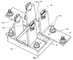
- FIG. 7 is a perspective view of a plurality of meter socket assemblies sitting in a basepan.
- FIG. 8 is a perspective view of a plurality an alternate type meter socket assemblies sitting in a basepan.
- FIG. 9 is a perspective view of a plurality of meter socket assemblies seated in a meter box enclosure housing.
- meter socket assembly 10 includes an extended bus bar 20 and a meter jaw assembly 30 .
- Meter jaw assembly 30 comprises a meter jaw 40 and jaw spring guide 50 that overlies meter jaw 40 .
- the extended bus bar 20 features a chamfered receptacle terminal 60 (see FIG. 2 ) that is coupled with meter jaw 40 .
- Chamfered receptacle terminal 60 creates a “V” shaped receptacle terminal with the upper portion of meter jaw 40 for easily inserting a meter blade (not shown) from a watt hour meter into the meter socket assembly 10 .
- the upper portion of the meter jaw 40 has an outward bend away from the chamfered receptacle terminal 60 .
- the middle portion of the meter jaw 40 has an outward joggle bend which then leans inward towards the extended bus bar 20 .
- the outward joggle bend shape helps meter jaw 40 fully contact the meter blade under load and also provides a bias spring force to press the meter blade to extended bus bar 20 .
- Extended bus bar 20 acts not only as a conductor to transmit electricity but also as a heat sink to quickly transfer away the heat generated during conduction.
- Jaw spring guide 50 provides the necessary bias spring force to reinforce and support meter jaw 40 so that meter jaw 40 and extended bus bar 20 hold the meter blade and allow extended bus bar 20 to maintain full contact with the meter blade during the watt hour meter's life time.
- the extended bus bar 20 , and meter jaw assembly 30 are mounted together with a fastening device 70 .
- the fastening device 70 is a screw. Others skilled in the art may select the fastening device 70 to be a clip, clamp, or a rivet element.
- meter socket assembly 10 comprises at least one cut out portion 80 on the top side of extended bus bar 20 .
- the cut out portion 80 allows space for housing the meter feet of the watt-hour meter upon attachment to the meter socket assembly 10 .
- the cut out portion 80 will be sized to specification and industry standard.
- Jaw spring guide 50 includes at least one arm guide 90 which leads and locates the meter blade into full contact position once the watt-hour meter is attached to the meter socket assembly 10 .
- Arm guide 90 acts as a locating guide for locating and securing the meter blade of the watt hour meter.
- Arm guide 90 also acts an anti rotation mechanism for the meter blade while being inserted into the meter socket assembly 10 .
- Arm guide 90 integrally extends from the main body portion of jaw spring guide 50 . Others skilled in the art may select to not include an arm guide 90 for the jaw spring guide 50 and others skilled in the art may select to use more than one arm guide 90 .
- meter socket assembly 10 includes a jaw spring guide 50 without an arm guide 90 for a ringless-type application.
- the jaw spring guide 50 is designed to leave an insertion space between the upper portion of meter jaw 40 and extended bus bar 20 when meter jaw 40 is in an open (no meter blade inserted) state.
- the insertion space is designed to maintain insertion and extraction forces over the meter blade of approximately 100 lbs to ensure that the bias spring force stays within the industry standard limits for watt hour meter insertion and extraction once the meter blade is inserted and pressed against the meter jaw 40 .
- the insertion space between meter jaw 40 and extended bus bar 20 facilitates of insertion and extraction of watt-hour meter blades.
- jaw spring guide 50 includes at least one locating feature 120 to locate the jaw spring guide 50 to the meter jaw 40 and extended bus bar 20 .
- Locating feature 120 will mate with shear guide 110 (show in FIG. 5 ). Others skilled in the art may select not to use locating feature 120 and shear guide 110 . Others skilled in the art may also include at least one locating feature 120 in the meter jaw 40 (see FIG. 5 ) and not include the at least one locating feature 120 in jaw spring guide 50 .
- extended bus bar 20 includes at least one shear guide 110 to locate and mate with the locating feature 120 on meter jaw 40 .
- Meter jaw 40 includes at least one locating feature 120 to mate with the shear guide 110 and to locate and align both the extended bus bar 20 and the meter jaw 40 to one another.
- meter jaw 40 is split cut in the middle to create (at least) two separated jaw fingers 130 .
- the separated jaw fingers 130 independently respond to the insertion of the meter blade and are able to absorb any slight misalignment of the meter blade along the insertion space between the meter jaw 40 and the extended bus bar 20 .
- Others skilled in the art may select to not split meter jaw 40 into separated jaw fingers 130 .
- Others skilled in the art may select to use a plurality separated jaw fingers 130 .
- FIG. 6 shows an alternative embodiment of the meter jaw assembly 10 .
- meter jaw 40 shows no split down the middle to create separated jaw fingers 130 .
- FIG. 6 does not include arm guide 90 or locating features 120 on the jaw spring guide 50 .
- FIG. 7 shows a plurality of meter socket assemblies 100 a - d mounted in a molded base pan 140 .
- the plurality of meter socket assemblies 100 a - d are mounted to molded base pan 140 using attachment devices 150 and 160 .
- attachment devices 150 and 160 are a screw or rivet and bolt respectively.
- Attachment device 160 is threaded into the extended bus bar 20 and secures the extended bus bar 20 to molded base pan 140 .
- insulating material may include plastic, porcelain or ceramic.
- Attachment device 160 also includes the standard nut and flat washers which are prepared for additional bus connections.
- Secondary attachment device 170 is a square or ribbed neck bolt that prevents the bolt from turning or falling out when the nut is tightened. Attachment device 170 also uses standard nut with spring washer and flat washer that are prepared for additional bus connections.
- the ribs 180 on molded base pan 140 locate the plurality of meter socket assemblies 100 a - d on assembly and as a result help guide the alignments for the meter blade insertion into the meter jaw 40 portions of the meter socket assemblies.
- the meter socket guide 210 (shown in FIG. 8 ) also aligns the meter socket assemblies 100 a - d on assembly. The meter socket guide 210 snaps between the meter socket assemblies 100 a - d on the cut out portion 80 against the inside of the extended bus bar 20 .
- the meter socket guide 210 ensures the horizontal and vertical alignments of the respective meter jaw 40 of the meter socket assemblies 100 a - d to provide precise fitting to watt-hour meter blades. Improved alignment of meter jaw 40 will allow easier insertion and extraction of the meter blade of the watt-hour meter and as a result improves the connection contact between meter jaw 40 and the meter blade. As a result of improved alignment, the connection contact will develop less heat under current load as the extended bus bar 20 will act as a heat sink and reduce heat from the connection contact.
- the molded base pan 140 has four mounting provisions to secure the plurality of meter socket assemblies 100 a - d and two mounting provisions 220 (see FIG. 8 ) to secure meter cover housing 190 .
- FIG. 8 shows a plurality of ringless type meter socket assemblies 100 a - d mounted into molded base pan 140 as described in FIG. 7 .
- the jaw spring guide 50 does not include arm guide 90 .
- the mater socket guide 210 With the mater socket guide 210 , the plurality of meter socket assemblies 100 a - d are aligned horizontally and vertically.
- meter cover housing 190 includes an opening 200 in the front wall of meter cover housing 190 .
- the meter cover 190 comprises a plurality of walls wherein an inner surface of back wall of meter cover housing 190 contains a plurality of meter socket assemblies 100 - a - d .
- the meter socket assemblies 100 a - d in its entirety is secured to the back wall of housing 190 through the four mounting provisions 220 on the molded base pan 140 (see FIG. 8 ).
Abstract
Description
Claims (26)
Priority Applications (1)
| Application Number | Priority Date | Filing Date | Title |
|---|---|---|---|
| US11/532,717 US7347722B2 (en) | 2005-09-16 | 2006-09-18 | Meter socket assembly |
Applications Claiming Priority (2)
| Application Number | Priority Date | Filing Date | Title |
|---|---|---|---|
| US71780205P | 2005-09-16 | 2005-09-16 | |
| US11/532,717 US7347722B2 (en) | 2005-09-16 | 2006-09-18 | Meter socket assembly |
Publications (2)
| Publication Number | Publication Date |
|---|---|
| US20070066131A1 US20070066131A1 (en) | 2007-03-22 |
| US7347722B2 true US7347722B2 (en) | 2008-03-25 |
Family
ID=37603187
Family Applications (1)
| Application Number | Title | Priority Date | Filing Date |
|---|---|---|---|
| US11/532,717 Active US7347722B2 (en) | 2005-09-16 | 2006-09-18 | Meter socket assembly |
Country Status (5)
| Country | Link |
|---|---|
| US (1) | US7347722B2 (en) |
| EP (1) | EP1924860A1 (en) |
| CN (1) | CN101263393B (en) |
| CA (1) | CA2622747C (en) |
| WO (1) | WO2007035643A1 (en) |
Cited By (8)
| Publication number | Priority date | Publication date | Assignee | Title |
|---|---|---|---|---|
| US20090061679A1 (en) * | 2007-08-27 | 2009-03-05 | Fan Zhang | Insulating meter jaw guide for a watt-hour meter socket |
| WO2011011564A1 (en) | 2009-07-23 | 2011-01-27 | Siemens Industry, Inc. | Lever bypass plug-in meter socket for electric watt-hour meters |
| US20130250488A1 (en) * | 2012-03-26 | 2013-09-26 | Siemens Industry, Inc. | Basepan assembly for an electrical enclosure |
| US8651894B1 (en) | 2012-08-03 | 2014-02-18 | Siemens Industry, Inc. | Meter socket having a breakable tab for retaining a sliding nut |
| DE102016116375A1 (en) | 2016-09-01 | 2018-03-01 | Lisa Dräxlmaier GmbH | CONTACTING DEVICE AND MANUFACTURING METHOD |
| US20190064213A1 (en) * | 2017-08-29 | 2019-02-28 | Siemens Industry, Inc. | Clamp jaw for by-pass type meter sockets |
| US20210328376A1 (en) * | 2020-04-20 | 2021-10-21 | Tyco Electronics (Shanghai) Co. Ltd. | Connector |
| US20220166176A1 (en) * | 2020-11-23 | 2022-05-26 | E.J. Brooks Company D.B.A. Brooks Utility Products Group | Watt-hour meter blade |
Families Citing this family (4)
| Publication number | Priority date | Publication date | Assignee | Title |
|---|---|---|---|---|
| US20070205012A1 (en) * | 2004-04-13 | 2007-09-06 | Dewalch Technologies, Inc. | Apparatus and method for securing an enclosure |
| US20090084144A1 (en) * | 2005-05-16 | 2009-04-02 | Stachowiak Jr John Edward | Method and Apparatus for Securing a Watthour Meter Box |
| GB2448130B (en) * | 2007-03-29 | 2009-12-23 | Actaris Uk Ltd | Electrical metering device |
| CN103048504A (en) * | 2012-12-14 | 2013-04-17 | 金华电业局 | Intelligent energy meter auxiliary terminal leaf-spring-type wire connector |
Citations (17)
| Publication number | Priority date | Publication date | Assignee | Title |
|---|---|---|---|---|
| US2218650A (en) * | 1939-05-16 | 1940-10-22 | States Company | Meter testing jack |
| US2626309A (en) * | 1949-10-01 | 1953-01-20 | Duncan Electric Mfg Co | Heavy-duty meter facilities |
| US3659243A (en) * | 1969-10-24 | 1972-04-25 | Amp Inc | Electrical connectors |
| US3714615A (en) | 1971-02-01 | 1973-01-30 | Westinghouse Electric Corp | Detachable meter mounting |
| US3764956A (en) * | 1971-12-27 | 1973-10-09 | Gen Switch Co | Electric meter socket |
| US3783343A (en) * | 1972-04-27 | 1974-01-01 | C Byland | Container in which a watthour meter and a meter socket are enclosably mountable and for readably displaying the watthour meter |
| US4201439A (en) | 1978-12-18 | 1980-05-06 | General Electric Company | Meter jaw and spring clip assembly |
| US4944692A (en) | 1989-02-24 | 1990-07-31 | Allina Edward F | Electrical plug-in connectors |
| US5334057A (en) | 1993-02-19 | 1994-08-02 | Blackwell Larry R | Connectors for electrical meter socket adapters |
| US5980311A (en) | 1997-12-09 | 1999-11-09 | Eaton Corporation | Fastenerless double ended clip-on meter jaw |
| US5997347A (en) * | 1996-06-03 | 1999-12-07 | Ekstrom Industries, Inc. | Watthour meter socket adapter with snap-on jaw contacts |
| US6104586A (en) * | 1997-11-20 | 2000-08-15 | Ekstrom Industries, Inc. | Circuit breaker switch apparatus |
| US6428350B1 (en) | 1999-06-07 | 2002-08-06 | Ekstrom Industries, Inc. | Watthour meter socket adapter with auxiliary component mounts |
| US6921290B1 (en) | 2004-03-09 | 2005-07-26 | Cooper Technologies Company | Socket assembly for an electric meter box |
| US7018247B1 (en) | 2005-03-22 | 2006-03-28 | Eaton Corporation | Clamp-jaw contact assembly with integral jaw spring and meter socket employing the same |
| US7040921B2 (en) | 2004-03-09 | 2006-05-09 | Cooper Technologies Company | Socket assembly for an electric meter box |
| US7106576B2 (en) * | 2004-05-18 | 2006-09-12 | Eaton Corporation | Jaw spacing stabilizer |
-
2006
- 2006-09-18 WO PCT/US2006/036302 patent/WO2007035643A1/en active Application Filing
- 2006-09-18 CA CA2622747A patent/CA2622747C/en not_active Expired - Fee Related
- 2006-09-18 EP EP06803782A patent/EP1924860A1/en not_active Withdrawn
- 2006-09-18 US US11/532,717 patent/US7347722B2/en active Active
- 2006-09-18 CN CN200680033661.8A patent/CN101263393B/en not_active Expired - Fee Related
Patent Citations (17)
| Publication number | Priority date | Publication date | Assignee | Title |
|---|---|---|---|---|
| US2218650A (en) * | 1939-05-16 | 1940-10-22 | States Company | Meter testing jack |
| US2626309A (en) * | 1949-10-01 | 1953-01-20 | Duncan Electric Mfg Co | Heavy-duty meter facilities |
| US3659243A (en) * | 1969-10-24 | 1972-04-25 | Amp Inc | Electrical connectors |
| US3714615A (en) | 1971-02-01 | 1973-01-30 | Westinghouse Electric Corp | Detachable meter mounting |
| US3764956A (en) * | 1971-12-27 | 1973-10-09 | Gen Switch Co | Electric meter socket |
| US3783343A (en) * | 1972-04-27 | 1974-01-01 | C Byland | Container in which a watthour meter and a meter socket are enclosably mountable and for readably displaying the watthour meter |
| US4201439A (en) | 1978-12-18 | 1980-05-06 | General Electric Company | Meter jaw and spring clip assembly |
| US4944692A (en) | 1989-02-24 | 1990-07-31 | Allina Edward F | Electrical plug-in connectors |
| US5334057A (en) | 1993-02-19 | 1994-08-02 | Blackwell Larry R | Connectors for electrical meter socket adapters |
| US5997347A (en) * | 1996-06-03 | 1999-12-07 | Ekstrom Industries, Inc. | Watthour meter socket adapter with snap-on jaw contacts |
| US6104586A (en) * | 1997-11-20 | 2000-08-15 | Ekstrom Industries, Inc. | Circuit breaker switch apparatus |
| US5980311A (en) | 1997-12-09 | 1999-11-09 | Eaton Corporation | Fastenerless double ended clip-on meter jaw |
| US6428350B1 (en) | 1999-06-07 | 2002-08-06 | Ekstrom Industries, Inc. | Watthour meter socket adapter with auxiliary component mounts |
| US6921290B1 (en) | 2004-03-09 | 2005-07-26 | Cooper Technologies Company | Socket assembly for an electric meter box |
| US7040921B2 (en) | 2004-03-09 | 2006-05-09 | Cooper Technologies Company | Socket assembly for an electric meter box |
| US7106576B2 (en) * | 2004-05-18 | 2006-09-12 | Eaton Corporation | Jaw spacing stabilizer |
| US7018247B1 (en) | 2005-03-22 | 2006-03-28 | Eaton Corporation | Clamp-jaw contact assembly with integral jaw spring and meter socket employing the same |
Cited By (15)
| Publication number | Priority date | Publication date | Assignee | Title |
|---|---|---|---|---|
| US7614908B2 (en) * | 2007-08-27 | 2009-11-10 | Siemens Energy & Automation, Inc. | Insulating meter jaw guide for a watt-hour meter socket |
| US20090061679A1 (en) * | 2007-08-27 | 2009-03-05 | Fan Zhang | Insulating meter jaw guide for a watt-hour meter socket |
| WO2011011564A1 (en) | 2009-07-23 | 2011-01-27 | Siemens Industry, Inc. | Lever bypass plug-in meter socket for electric watt-hour meters |
| US20110021067A1 (en) * | 2009-07-23 | 2011-01-27 | Siemens Industry, Inc. | Lever Bypass Plug-In Meter Socket for Electric Watt-Hour Meters |
| US8182282B2 (en) * | 2009-07-23 | 2012-05-22 | Siemens Industry, Inc. | Lever bypass plug-in meter socket for electric watt-hour meters |
| US8717743B2 (en) * | 2012-03-26 | 2014-05-06 | Siemens Industry, Inc. | Basepan assembly for an electrical enclosure |
| US20130250488A1 (en) * | 2012-03-26 | 2013-09-26 | Siemens Industry, Inc. | Basepan assembly for an electrical enclosure |
| US8651894B1 (en) | 2012-08-03 | 2014-02-18 | Siemens Industry, Inc. | Meter socket having a breakable tab for retaining a sliding nut |
| DE102016116375A1 (en) | 2016-09-01 | 2018-03-01 | Lisa Dräxlmaier GmbH | CONTACTING DEVICE AND MANUFACTURING METHOD |
| DE102016116375B4 (en) | 2016-09-01 | 2023-10-05 | Lisa Dräxlmaier GmbH | CONTACTING DEVICE |
| US20190064213A1 (en) * | 2017-08-29 | 2019-02-28 | Siemens Industry, Inc. | Clamp jaw for by-pass type meter sockets |
| US10498063B2 (en) * | 2017-08-29 | 2019-12-03 | Siemens Industry, Inc. | Clamp jaw for by-pass type meter sockets |
| US20210328376A1 (en) * | 2020-04-20 | 2021-10-21 | Tyco Electronics (Shanghai) Co. Ltd. | Connector |
| US11695230B2 (en) * | 2020-04-20 | 2023-07-04 | Tyco Electronics (Shanghai) Co., Ltd. | Connector including a terminal with a pair of sub-terminals |
| US20220166176A1 (en) * | 2020-11-23 | 2022-05-26 | E.J. Brooks Company D.B.A. Brooks Utility Products Group | Watt-hour meter blade |
Also Published As
| Publication number | Publication date |
|---|---|
| WO2007035643A1 (en) | 2007-03-29 |
| CA2622747A1 (en) | 2007-03-29 |
| CA2622747C (en) | 2013-05-28 |
| CN101263393B (en) | 2013-02-06 |
| CN101263393A (en) | 2008-09-10 |
| US20070066131A1 (en) | 2007-03-22 |
| EP1924860A1 (en) | 2008-05-28 |
Similar Documents
| Publication | Publication Date | Title |
|---|---|---|
| US7347722B2 (en) | Meter socket assembly | |
| US6178106B1 (en) | Power distribution center with improved power supply connection | |
| US6561844B1 (en) | Lug for providing both electrical and mechanical connection between buses and watt hour meter sockets | |
| US6315580B1 (en) | PCB connector module for plug-in circuit breakers and fuses | |
| JP5224179B2 (en) | Spring force connection device | |
| US6280264B1 (en) | Terminal connector securing wire with a wide range of diameters to a conductor of an electric power switch and an electric power switch incorporating the terminal connector | |
| US6530811B1 (en) | Modular distribution assembly | |
| US7889480B2 (en) | Panelboard | |
| US20080153362A1 (en) | Multi-terminal block for electronic devices having superimposed conductor connecting levels | |
| CN101017750B (en) | Fuse strip with lateral outgoing contacts and a lateral adapter module | |
| US20110314671A1 (en) | Touch safe fuse module with improved wiring lugs | |
| US8529291B2 (en) | Wall bushing plug connector and fastening element for it | |
| CN104254949B (en) | Plug-in connector | |
| US20100130042A1 (en) | Connector socket, a connector plug, and an appliance fitted with a connector | |
| CA2260500C (en) | Power supply device | |
| JP3526240B2 (en) | Terminal connection structure of electrical junction box | |
| JP2008109808A (en) | Distribution panel | |
| US4203146A (en) | Multiple metering panelboard assembly | |
| US6939153B1 (en) | Double “E” electrical distribution block | |
| US8182282B2 (en) | Lever bypass plug-in meter socket for electric watt-hour meters | |
| JP2006271174A (en) | Distribution board | |
| TWI459671B (en) | Connected conductor for electrical power | |
| JPH0212780A (en) | Electric connection terminal having chocking screw | |
| US8932088B2 (en) | Anti-turn mechanism for multiple connector sizes | |
| CN218631894U (en) | Wiring fuse mounting base |
Legal Events
| Date | Code | Title | Description |
|---|---|---|---|
| AS | Assignment |
Owner name: SIEMENS ENERGY & AUTOMATION, INC., GEORGIA Free format text: ASSIGNMENT OF ASSIGNORS INTEREST;ASSIGNORS:ZHANG, FAN;ROGERS, KENNETH;MONTALBO, ROLAND JOSEPH;REEL/FRAME:018270/0621 Effective date: 20060911 |
|
| STCF | Information on status: patent grant |
Free format text: PATENTED CASE |
|
| AS | Assignment |
Owner name: SIEMENS INDUSTRY, INC.,GEORGIA Free format text: MERGER;ASSIGNOR:SIEMENS ENERGY AND AUTOMATION AND SIEMENS BUILDING TECHNOLOGIES, INC.;REEL/FRAME:024411/0223 Effective date: 20090923 Owner name: SIEMENS INDUSTRY, INC., GEORGIA Free format text: MERGER;ASSIGNOR:SIEMENS ENERGY AND AUTOMATION AND SIEMENS BUILDING TECHNOLOGIES, INC.;REEL/FRAME:024411/0223 Effective date: 20090923 |
|
| FPAY | Fee payment |
Year of fee payment: 4 |
|
| FPAY | Fee payment |
Year of fee payment: 8 |
|
| MAFP | Maintenance fee payment |
Free format text: PAYMENT OF MAINTENANCE FEE, 12TH YEAR, LARGE ENTITY (ORIGINAL EVENT CODE: M1553); ENTITY STATUS OF PATENT OWNER: LARGE ENTITY Year of fee payment: 12 |